
Create successful ePaper yourself
Turn your PDF publications into a flip-book with our unique Google optimized e-Paper software.
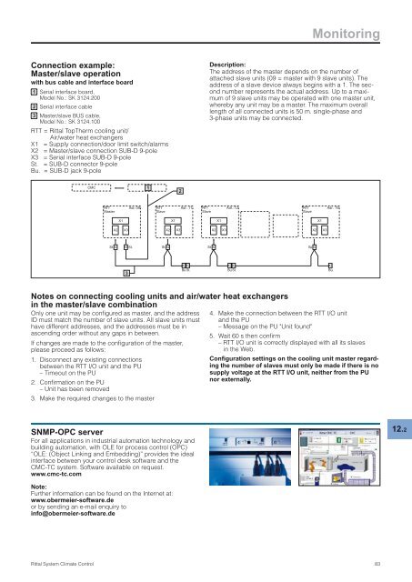
Connection example:<br />
Master/slave operation<br />
with bus cable and interface board<br />
1 Serial interface board,<br />
Model No.: <strong>SK</strong> 3124.200<br />
2 Serial interface cable<br />
3 Master/slave BUS cable,<br />
Model No.: <strong>SK</strong> 3124.100<br />
RTT = <strong>Rittal</strong> TopTherm cooling unit/<br />
Air/water heat exchangers<br />
X1 = Supply connection/door limit switch/alarms<br />
X2 = Master/slave connection SUB-D 9-pole<br />
X3 = Serial interface SUB-D 9-pole<br />
St. = SUB-D connector 9-pole<br />
Bu. = SUB-D jack 9-pole<br />
CMC<br />
<strong>Rittal</strong> <strong>System</strong> <strong>Climate</strong> <strong>Control</strong><br />
RTT<br />
Master<br />
X1<br />
X2 X3<br />
Adr.: 09<br />
RTT<br />
Slave<br />
X1<br />
X2 X3<br />
Adr.: 11<br />
St. X2 X3 St. St. X2<br />
St. X2<br />
3<br />
1<br />
2<br />
RTT<br />
Slave<br />
Monitoring<br />
Description:<br />
The address of the master depends on the number of<br />
attached slave units (09 = master with 9 slave units). The<br />
address of a slave device always begins with a 1. The second<br />
number represents the actual address. Up to a maximum<br />
of 9 slave units may be operated with one master unit,<br />
whereby any unit may be a master. The maximum overall<br />
length of all connected units is 50 m. single-phase and<br />
3-phase units may be connected.<br />
X1<br />
X2 X3<br />
Adr.: 12<br />
RTT<br />
Slave<br />
St. X2<br />
X1<br />
X2 X3<br />
X2 X2 X2 X2<br />
X2<br />
Bu. St.<br />
Bu. St.<br />
Bu.<br />
Notes on connecting cooling units and air/water heat exchangers<br />
in the master/slave combination<br />
Only one unit may be configured as master, and the address<br />
ID must match the number of slave units. All slave units must<br />
have different addresses, and the addresses must be in<br />
ascending order without any gaps in between.<br />
If changes are made to the configuration of the master,<br />
please proceed as follows:<br />
1. Disconnect any existing connections<br />
between the RTT I/O unit and the PU<br />
<strong>–</strong> Timeout on the PU<br />
2. Confirmation on the PU<br />
<strong>–</strong> Unit has been removed<br />
3. Make the required changes to the master<br />
SNMP-OPC server<br />
For all applications in industrial automation technology and<br />
building automation, with OLE for process control (OPC)<br />
“OLE: (Object Linking and Embedding)” provides the ideal<br />
interface between your control desk software and the<br />
CMC-TC system. Software available on request.<br />
www.cmc-tc.com<br />
Note:<br />
Further information can be found on the Internet at:<br />
www.obermeier-software.de<br />
or by sending an e-mail enquiry to<br />
info@obermeier-software.de<br />
Adr.: 19<br />
4. Make the connection between the RTT I/O unit<br />
and the PU<br />
<strong>–</strong> Message on the PU "Unit found"<br />
5. Wait 60 s then confirm<br />
<strong>–</strong> RTT I/O unit is correctly displayed with all its slaves<br />
in the Web.<br />
Configuration settings on the cooling unit master regarding<br />
the number of slaves must only be made if there is no<br />
supply voltage at the RTT I/O unit, neither from the PU<br />
nor externally.<br />
83<br />
12.2