

310665E, Xtreme Mix, Plural Component Proportioner ... - Graco Inc.
310665E, Xtreme Mix, Plural Component Proportioner ... - Graco Inc.
310665E, Xtreme Mix, Plural Component Proportioner ... - Graco Inc.

You also want an ePaper? Increase the reach of your titles
YUMPU automatically turns print PDFs into web optimized ePapers that Google loves.
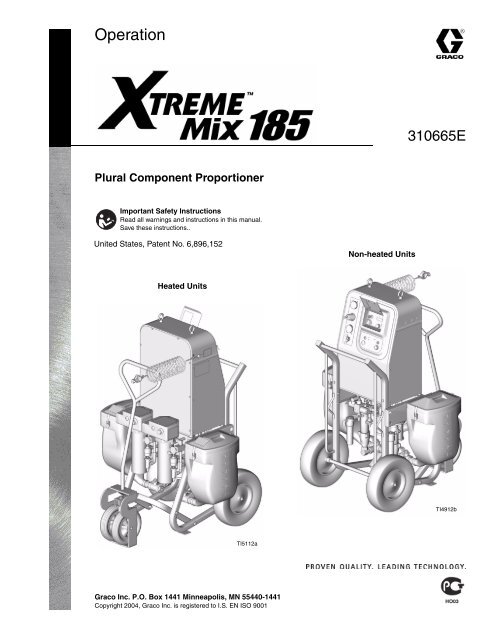
Operation<br />
<strong>Plural</strong> <strong>Component</strong> <strong>Proportioner</strong><br />
Important Safety Instructions<br />
Read all warnings and instructions in this manual.<br />
Save these instructions..<br />
United States, Patent No. 6,896,152<br />
Heated Units<br />
TI5112a<br />
<strong>Graco</strong> <strong>Inc</strong>. P.O. Box 1441 Minneapolis, MN 55440-1441<br />
Copyright 2004, <strong>Graco</strong> <strong>Inc</strong>. is registered to I.S. EN ISO 9001<br />
Non-heated Units<br />
<strong>310665E</strong><br />
TI4912b
Contents<br />
Contents . . . . . . . . . . . . . . . . . . . . . . . . . . . . . . . . . . 2<br />
Manual Conventions . . . . . . . . . . . . . . . . . . . . . . . . 2<br />
<strong>Xtreme</strong> <strong>Mix</strong> 185 Models . . . . . . . . . . . . . . . . . . . . . . 3<br />
Related Manuals . . . . . . . . . . . . . . . . . . . . . . . . . . . 4<br />
Warnings . . . . . . . . . . . . . . . . . . . . . . . . . . . . . . . . . 5<br />
Overview . . . . . . . . . . . . . . . . . . . . . . . . . . . . . . . . . . 7<br />
Usage . . . . . . . . . . . . . . . . . . . . . . . . . . . . . . . . . 7<br />
User Interface . . . . . . . . . . . . . . . . . . . . . . . . . . . 7<br />
Installation . . . . . . . . . . . . . . . . . . . . . . . . . . . . . . . . 8<br />
Wall Mounting . . . . . . . . . . . . . . . . . . . . . . . . . . . 8<br />
Heated Units . . . . . . . . . . . . . . . . . . . . . . . . . . . . 8<br />
Air Controls . . . . . . . . . . . . . . . . . . . . . . . . . . . . . 8<br />
Solenoid Module . . . . . . . . . . . . . . . . . . . . . . . . . 8<br />
Fluid Controls . . . . . . . . . . . . . . . . . . . . . . . . . . 10<br />
Proper Lifting of Unit . . . . . . . . . . . . . . . . . . . . . 10<br />
Setup . . . . . . . . . . . . . . . . . . . . . . . . . . . . . . . . . . . . 12<br />
Pressure Relief Procedure . . . . . . . . . . . . . . . . . . 14<br />
Fluid Manifold to Gun . . . . . . . . . . . . . . . . . . . . 14<br />
Pump to Fluid Manifold . . . . . . . . . . . . . . . . . . . 15<br />
Manual Conventions<br />
Note:<br />
WARNING<br />
WARNING: a potentially hazardous situation which, if<br />
not avoided, could result in death or serious injury.<br />
CAUTION<br />
CAUTION: a potentially hazardous situation which, if<br />
not avoided, may result in property damage or destruction<br />
of equipment.<br />
Additional helpful information.<br />
Contents<br />
Flushing . . . . . . . . . . . . . . . . . . . . . . . . . . . . . . . . . 16<br />
Fluid Manifold Flushing . . . . . . . . . . . . . . . . . . . 16<br />
Full System Flushing . . . . . . . . . . . . . . . . . . . . . 20<br />
Priming . . . . . . . . . . . . . . . . . . . . . . . . . . . . . . . . . . 22<br />
Pump Test . . . . . . . . . . . . . . . . . . . . . . . . . . . . . . . . 24<br />
Spraying . . . . . . . . . . . . . . . . . . . . . . . . . . . . . . . . . 26<br />
<strong>Mix</strong> and Integration Tests . . . . . . . . . . . . . . . . . . . 27<br />
Batch Dispense or Ratio Check . . . . . . . . . . . . . . 28<br />
Pot Life Timer . . . . . . . . . . . . . . . . . . . . . . . . . . . . . 29<br />
Recirculation Setting . . . . . . . . . . . . . . . . . . . . . . . 30<br />
Shutdown . . . . . . . . . . . . . . . . . . . . . . . . . . . . . . . . 31<br />
Recalibrate System . . . . . . . . . . . . . . . . . . . . . . . . 32<br />
Set Pump Calibration Value . . . . . . . . . . . . . . . . 32<br />
Calibrate Pump Sensor . . . . . . . . . . . . . . . . . . . 32<br />
Alarms . . . . . . . . . . . . . . . . . . . . . . . . . . . . . . . . . . . 33<br />
Performance Charts . . . . . . . . . . . . . . . . . . . . . . . . 35<br />
Technical Data . . . . . . . . . . . . . . . . . . . . . . . . . . . . 36<br />
Dimensions . . . . . . . . . . . . . . . . . . . . . . . . . . . . . . . 37<br />
Wall Mounting Diagram . . . . . . . . . . . . . . . . . . . . . 37<br />
<strong>Graco</strong> Standard Warranty . . . . . . . . . . . . . . . . . . . 38<br />
<strong>Graco</strong> Information . . . . . . . . . . . . . . . . . . . . . . . . . 38<br />
Warnings in the instruction sections (such as “Installation”)<br />
generally include a symbol indicating the hazard.<br />
Follow the instructions and read the hazard section on<br />
the general warning pages 5-6 for additional information.<br />
Example:<br />
WARNING<br />
Your system must be grounded. Read warnings,<br />
page 5 and follow instructions below.<br />
2 <strong>310665E</strong>
<strong>Xtreme</strong> <strong>Mix</strong> 185 Models<br />
WARNING<br />
Do not install equipment approved only for non-hazardous<br />
location in a hazardous area. Substitution of<br />
components may impair intrinsic safety and cause personal<br />
injury. Read page 5.<br />
Continued on page 4.<br />
Approved for Hazardous Location<br />
Class I, Div 1, Group D (North America); Class I, Zones 1 and 2 (Europe)<br />
<strong>Xtreme</strong><br />
<strong>Mix</strong> 185<br />
Part No. Series Description<br />
234614 A Wall mount, Hydra<strong>Mix</strong> 700<br />
carbon steel Pumps, with<br />
hose and gun<br />
234616 A Cart mount, Hydra<strong>Mix</strong> 700<br />
carbon steel Pumps, with<br />
hose and gun<br />
Non-heated Units<br />
Maximum<br />
Working Pressure<br />
psi (MPa, bar) Approvals<br />
4700 (32, 324)<br />
4700 (32, 324)<br />
234838 A Cart mount, Hydra<strong>Mix</strong> 700<br />
carbon steel Pumps, 240V<br />
Heated Units<br />
4700 (32, 324)<br />
Heaters (16.2 A each, 32.4 A<br />
total), with hose and gun<br />
234840 A Cart mount, Hydra<strong>Mix</strong> 700<br />
carbon steel Pumps, 480V<br />
Heaters (8.3 A each, 16.6 A<br />
total), with hose and gun<br />
4700 (32, 324)<br />
Conforms to<br />
FM std 3600 & 3610<br />
for use in<br />
Class I Div 1<br />
Group D T3<br />
Hazardous Locations<br />
Conforms to<br />
FM std 3600 & 3610<br />
for use in<br />
Class I Div 1<br />
Group D T2<br />
Hazardous Locations<br />
<strong>Xtreme</strong> <strong>Mix</strong> 185 Models<br />
ISSeP 04 ATEX 020X<br />
EEx ia p IIA T3<br />
CAN/CSA<br />
22.2 No. 157-92<br />
& No. 1010.1-92<br />
ISSeP04ATEX098X<br />
EEx ia p d IIA T2<br />
CAN/CSA<br />
22.2 No. 157-92<br />
& No. 1010.1-92<br />
<strong>310665E</strong> 3
234615 A<br />
Approved for Non-hazardous Location<br />
Wall mount, Hydra<strong>Mix</strong> 700 carbon steel Pumps,<br />
Non-heated, with hose and gun<br />
234617 A Cart mount, Hydra<strong>Mix</strong> 700 carbon steel Pumps,<br />
Non-heated, with hose and gun<br />
234839 A Cart mount, Hydra<strong>Mix</strong> 700 carbon steel Pumps,<br />
240V Heaters (16.2 A each, 32.4 A total), with hose<br />
and gun<br />
234841 A Cart mount, Hydra<strong>Mix</strong> 700 carbon steel Pumps,<br />
480V Heaters (8.3 A each, 16.6 A total), with hose<br />
and gun<br />
Related Manuals<br />
4700 (32, 324)<br />
4700 (32, 324)<br />
4700 (32, 324)<br />
Related Manuals<br />
<strong>Component</strong> Manuals in English This manual available in the following languages:<br />
Manual Description<br />
310665 <strong>Xtreme</strong> <strong>Mix</strong> 185 Operation<br />
310666 <strong>Xtreme</strong> <strong>Mix</strong> 185 Repair-Parts<br />
310654 Fluid <strong>Mix</strong> Manifold<br />
310655 Dispense Valve<br />
310662 Displacement Pumps<br />
310672 Hydra<strong>Mix</strong> Pumps<br />
310673 Circulation Kits<br />
310675 AC Power Supply<br />
310676 Remote Manifold Kit<br />
310677 Heater Installation Kit<br />
310678 TSL Pump Kits<br />
309192 ISO Supply Kit<br />
312145 XTR Airless Spray Gun<br />
309524 VISCON HP Heater<br />
309623 Data Download Kits<br />
308034 Turbine Alternator Repair Kit<br />
Manual Language<br />
310665 English<br />
310701 French<br />
310703 Spanish<br />
310705 German<br />
310707 Korean<br />
310709 Chinese<br />
310711 Japanese<br />
4700 (32, 324)<br />
4 <strong>310665E</strong>
Warnings<br />
Warnings<br />
The following warnings include general safety information for this equipment. More specific warnings are included in<br />
the text where applicable.<br />
WARNING<br />
FIRE AND EXPLOSION HAZARD<br />
Flammable fumes, such as solvent and paint fumes, in work area can ignite or explode. To help prevent<br />
fire and explosion:<br />
Use equipment only in well ventilated area.<br />
Eliminate all ignition sources; such as pilot lights, cigarettes, portable electric lamps, and plastic drop<br />
cloths (potential static arc).<br />
Keep work area free of debris, including solvent, rags and gasoline.<br />
Do not plug or unplug power cords or turn lights on or off when flammable fumes are present.<br />
Ground equipment and conductive objects in work area. See Setup instructions.<br />
Use only grounded hoses.<br />
Hold gun firmly to side of grounded pail when triggering into pail.<br />
If there is static sparking or you feel a shock, stop operation immediately. Do not use equipment<br />
until you identify and correct the problem.<br />
SKIN INJECTION HAZARD<br />
High-pressure fluid from gun, hose leaks, or ruptured components will pierce skin. This may look like just<br />
a cut, but it is a serious injury that can result in amputation. Get immediate surgical treatment.<br />
Do not point gun at anyone or at any part of the body.<br />
Do not put your hand over the spray tip.<br />
Do not stop or deflect leaks with your hand, body, glove, or rag.<br />
Do not spray without tip guard and trigger guard installed.<br />
Engage trigger lock when not spraying.<br />
Follow Pressure Relief Procedure in this manual, when you stop spraying and before cleaning,<br />
checking, or servicing equipment.<br />
MOVING PARTS HAZARD<br />
Moving parts can pinch or amputate fingers and other body parts.<br />
Keep clear of moving parts.<br />
Do not operate equipment with protective guards or covers removed.<br />
Pressurized equipment can start without warning. Before checking, moving, or servicing equipment,<br />
follow the Pressure Relief Procedure in this manual. Disconnect power or air supply.<br />
<strong>310665E</strong> 5
WARNING<br />
Warning<br />
EQUIPMENT MISUSE HAZARD<br />
Misuse can cause death or serious injury.<br />
Do not exceed the maximum working pressure or temperature rating of the lowest rated system component.<br />
See Technical Data in all equipment manuals.<br />
Use fluids and solvents that are compatible with equipment wetted parts. See Technical Data in all<br />
equipment manuals. Read fluid and solvent manufacturer’s warnings.<br />
Check equipment daily. Repair or replace worn or damaged parts immediately.<br />
Do not alter or modify equipment.<br />
For professional use only.<br />
Use equipment only for its intended purpose. Call your <strong>Graco</strong> distributor for information.<br />
Route hoses and cables away from traffic areas, sharp edges, moving parts, and hot surfaces.<br />
Do not use hoses to pull equipment.<br />
Comply with all applicable safety regulations.<br />
TOXIC FLUID OR FUMES HAZARD<br />
Toxic fluids or fumes can cause serious injury or death if splashed in the eyes or on skin, inhaled, or swallowed.<br />
Read MSDS’s to know the specific hazards of the fluids you are using.<br />
Store hazardous fluid in approved containers, and dispose of it according to applicable guidelines.<br />
BURN HAZARD<br />
Equipment surfaces and fluid that’s heated can become very hot during operation. To avoid severe burns,<br />
do not touch hot fluid or equipment. Wait until equipment/fluid has cooled completely.<br />
PERSONAL PROTECTIVE EQUIPMENT<br />
You must wear appropriate protective equipment when operating, servicing, or when in the operating<br />
area of the equipment to help protect you from serious injury, including eye injury, inhalation of toxic<br />
fumes, burns, and hearing loss. This equipment includes but is not limited to:<br />
Protective eyewear<br />
Clothing and respirator as recommended by the fluid and solvent manufacturer<br />
Gloves<br />
Hearing protection<br />
RECOIL HAZARD<br />
Brace yourself; gun may recoil when triggered and cause you to fall, which could cause serious injury.<br />
6 <strong>310665E</strong>
Overview<br />
Usage<br />
The <strong>Xtreme</strong> <strong>Mix</strong> 185 can mix most two-component<br />
paints. It is not for use with “quick-setting” paints (those<br />
with a pot life of less than 5 minutes) without modification.<br />
Contact your distributor for information.<br />
The <strong>Xtreme</strong> <strong>Mix</strong> 185 is operated with the User Interface,<br />
Air Controls and Fluid Controls, described below and on<br />
page 8. Refer to FIG. 1 and FIG. 4.<br />
User Interface<br />
The User Interface has 6 main interfaces.<br />
1. Function Knob to select desired function:<br />
Icon Function<br />
Spray: proportion and spray material.<br />
Run A: operate A independent of B (priming,<br />
flushing) for 12 cycles.<br />
Run B: operate B independent of A (priming,<br />
flushing) for 12 cycles.<br />
Batch Dispense: dispense proportioned<br />
amounts of A and B (1 pint/500 cc).<br />
Pump Test: dispense predetermined<br />
amount of A and B to verify pump operation.<br />
Recirculation: circulate fluid A and/or B up<br />
to the mix manifold.<br />
Pot Life Timer: display potlife time left.<br />
Pressure Relief/Park: allows pressure relief<br />
and runs pumps to the bottom of stroke.<br />
See page 14.<br />
System totalizers count in Spray and Batch<br />
Dispense functions only.<br />
A and B Indicators (LT) show which dispense<br />
valve(s) is open.<br />
2. Start button to initiate functions.<br />
3. Stop button to terminate functions.<br />
Overview<br />
4. Key switch to change ratio, pot life time, pot life volume,<br />
or calibration data.<br />
5. Display (five digits) to view:<br />
Software revision level at startup<br />
Ratio<br />
Pot life time and reset volume<br />
Alarm codes<br />
Sensor calibration factor.<br />
6. Data port allows for connection to a PC serial port<br />
to download volume totalizer, operation, ratio setting,<br />
and error alarm data, and to change internal<br />
settings.<br />
WARNING<br />
To avoid impairing intrinsic safety and reduce the risk<br />
of fire and explosion, the PC must be in a non-hazardous<br />
location and a safety barrier must be installed<br />
between the PC and <strong>Xtreme</strong> <strong>Mix</strong> 185 unit. See <strong>Xtreme</strong><br />
<strong>Mix</strong> 185 data download manual 309623.<br />
FIG. 1. User Interface<br />
You must recalibrate the circuit board whenever the<br />
main circuit board, software, or sensor is replaced,<br />
or when Alarm 8 occurs. See Recalibrate System,<br />
page 32.<br />
<strong>310665E</strong> 7<br />
4<br />
6<br />
3<br />
LT<br />
5<br />
1<br />
2
Installation<br />
The Typical Installation shown in FIG. 2 is not an actual<br />
system design. Contact your <strong>Graco</strong> distributor for assistance<br />
in designing your system. Be sure all accessories<br />
are adequately sized and pressure-rated to meet system<br />
requirements.<br />
Reference numbers and letters in the text refer to numbers<br />
and letters in the figures.<br />
Icons in the text refer to icons on the User Interface.<br />
Wall Mounting<br />
Part Nos. 234614 and 234615 are wall mount units.<br />
1. Ensure that the wall and mounting hardware are<br />
strong enough to support the weight of the equipment,<br />
fluid, hoses, and stress caused during operation.<br />
2. Using the equipment as a template, mark the<br />
mounting holes on the wall at a convenient height<br />
for the operator and so equipment is easily accessible<br />
for maintenance. Ensure that the equipment is<br />
level. See Wall Mounting Diagram, page 37.<br />
3. Drill mounting holes in the wall. Install anchors as<br />
needed.<br />
4. Bolt equipment securely to the wall.<br />
Heated Units<br />
Part Nos. 234838, 234839, 234840, and 234841 include<br />
two VISCON HP Fluid Heaters.<br />
1. Ensure that the electrical power supply meets the<br />
following requirements.<br />
<strong>Xtreme</strong> <strong>Mix</strong> 185<br />
Part No.<br />
Heater<br />
Voltage<br />
Heater Amperage<br />
234838 240V 16.2 A each, 32.4 A total<br />
234839 240V 16.2 A each, 32.4 A total<br />
234840 480V 8.3 A each, 16.6 A total<br />
234841 480V 8.3 A each, 16.6 A total<br />
2. Read and follow all heater wiring instructions in the<br />
heater manual, 309524.<br />
Air Controls<br />
See FIG. 2.<br />
Installation<br />
Bleed-type main air shutoff valve (D), to shutoff<br />
all air to <strong>Xtreme</strong> <strong>Mix</strong> 185 (including controller<br />
power).<br />
Supply air pressure gauge (E), to monitor air pressure<br />
to <strong>Xtreme</strong> <strong>Mix</strong> 185.<br />
A minimum air pressure supply of 70 psi (483 kPa,<br />
4.8 bar) must be maintained for the <strong>Xtreme</strong> <strong>Mix</strong><br />
185 to operate properly.<br />
Pump air pressure regulator (F) with gauge (G),<br />
to adjust and monitor pump air pressure.<br />
Solenoid Module<br />
There are two solenoids inside the pneumatic control<br />
box, one to actuate dispense valve A, one to actuate<br />
dispense valve B.<br />
Heated units include a third solenoid (R), for the<br />
circulation valves.<br />
8 <strong>310665E</strong><br />
1<br />
1<br />
A BR<br />
Third solenoid is present on<br />
heated units only.<br />
TI5166a
G<br />
F<br />
E<br />
D<br />
J<br />
C<br />
H<br />
S<br />
M<br />
FIG. 2. Typical Installation<br />
Key for FIG. 2<br />
A <strong>Xtreme</strong> <strong>Mix</strong> 185 <strong>Plural</strong> <strong>Component</strong> <strong>Proportioner</strong><br />
B User Interface (see page 7)<br />
C <strong>Mix</strong> Manifold<br />
D Bleed-Type Main Air Shutoff Valve<br />
E Air Supply Pressure Gauge<br />
F Pump Air Regulator<br />
G Pump Air Pressure Gauge<br />
H <strong>Component</strong> A Pump<br />
J <strong>Component</strong> A Fluid Supply<br />
A<br />
T<br />
Detail of Heated Units<br />
K <strong>Component</strong> B Pump<br />
L <strong>Component</strong> B Fluid Supply<br />
M Gun Fluid Hose<br />
N Static <strong>Mix</strong>er<br />
P Fluid Whip Hose<br />
R Airless Spray Gun<br />
S <strong>Proportioner</strong> Air Supply LIne<br />
T Ground Wire<br />
U Fluid Heaters (heated units only)<br />
V Circulation Valves (heated units only)<br />
Installation<br />
<strong>310665E</strong> 9<br />
U B<br />
B<br />
N<br />
L<br />
K<br />
V B<br />
R<br />
P<br />
V A<br />
U A<br />
TI5112a<br />
TI4953c
Fluid Controls<br />
The <strong>Xtreme</strong> <strong>Mix</strong> 185 mix manifold includes the following<br />
fluid controls. See manual 310654 for complete information<br />
about the mix manifold. See FIG. 4.<br />
Dispense valves (F A , F B ) dispense component A<br />
and component B. Solenoids A and B turn the dispense<br />
valves ON and OFF.<br />
Shutoff valves (G A , G B ) shutoff fluid A or B from<br />
entering the fluid manifold.<br />
Sampling valves (H A , H B ), to batch dispense or<br />
test pumps/meters.<br />
Solvent purge valves (J A , J B ) allow solvent to<br />
enter the fluid manifold.<br />
Circulation valves (V A , V B ) circulate component A<br />
and component B back to the supply containers.<br />
Solenoid R turns the valves ON and OFF. <strong>Inc</strong>luded<br />
with heated units. See FIG. 2 detail.<br />
<strong>Component</strong> A Dispense<br />
Solenoid A opens dispense valve A. The correct dose of<br />
component A flows into the mix manifold. Solenoid A<br />
closes dispense valve A. See FIG. 4.<br />
<strong>Component</strong> B Dispense<br />
Solenoid B opens dispense valve B. The correct dose of<br />
component B flows into the mix manifold. Solenoid B<br />
closes dispense valve B. <strong>Component</strong>s A and B are<br />
mixed in the 50 ft (15.2 m) fluid hose (M), then uniformly<br />
blended in the static mixer (N).<br />
Proper Lifting of Unit<br />
WARNING<br />
Installation<br />
Follow instructions below to avoid dropping or swinging<br />
unit or being struck by the cart handle, which can<br />
cause serious injury or damage to equipment.<br />
Either remove the cart handle or secure it to the cart<br />
before lifting the unit. Connect a bridle swing, hooking<br />
an end to each of the <strong>Xtreme</strong> <strong>Mix</strong> 185 lift rings. Hook the<br />
center ring on a hoist. See FIG. 3. Carefully lift the<br />
<strong>Xtreme</strong> <strong>Mix</strong> 185 unit; make sure it balances evenly.<br />
FIG. 3<br />
TI4956a<br />
10 <strong>310665E</strong>
F A OFF<br />
F A ON<br />
FIG. 4. Fluid <strong>Mix</strong> Manifold<br />
F A<br />
F B OFF<br />
H A<br />
G A<br />
F B ON<br />
J A<br />
Installation<br />
<strong>310665E</strong> 11<br />
F B<br />
M<br />
G B<br />
J B<br />
H B
Setup<br />
WARNING<br />
Do not install equipment approved only for non-hazardous<br />
location in a hazardous area. Substitution of<br />
components may impair intrinsic safety and cause personal<br />
injury. Read warnings, page 5. Ground equipment<br />
as instructed below.<br />
1. Connect <strong>Xtreme</strong> <strong>Mix</strong> 185 ground wire (T) to a true<br />
earth ground.<br />
T<br />
TI4792a<br />
4. Tighten all fittings on unit.<br />
Setup<br />
2. The 50 ft. (15 m) fluid hose (M), static mixer (N), and<br />
whip hose (P) come assembled. Note the order of<br />
connection.<br />
CAUTION<br />
Do not assemble static mixer (N) directly to fluid manifold.<br />
Install static mixer after first 50 ft. (15 m) of hose<br />
to ensure material is completely mixed. Spraying<br />
unmixed material could necessitate rework of part<br />
sprayed.<br />
3. Connect the fluid hose (M) to the fluid manifold outlet.<br />
Do not install gun spray tip yet.<br />
5. Fill pump A and B packing nuts with throat seal liquid<br />
(TSL).<br />
12 <strong>310665E</strong><br />
M<br />
N<br />
R<br />
P<br />
TI4954b
6. Connect air supply line (S) to air inlet.<br />
Air supply requirement: 110 psi (0.8 MPa, 8 bar)<br />
maximum, 70 psi (483 kPa, 4.8 bar) minimum.<br />
Flow volume required: 20 scfm minimum; 125<br />
scfm maximum.<br />
7. Set air regulator to 0.<br />
8. Open main air shutoff valve. When starting up, display<br />
will show “88888”, then software revision, then<br />
current ratio (if set to or ).<br />
9. Setup ratio.<br />
a. Turn function knob to .<br />
b. Current ratio displays.<br />
Setup<br />
c. To change ratio, turn key to + or – until desired<br />
ratio is displayed, then turn key back to neutral.<br />
10. Flush and prime system. See pages 16 and 22. Run<br />
Pump Test, page 24 to check ratio accuracy.<br />
<strong>310665E</strong> 13
Pressure Relief<br />
Procedure<br />
WARNING<br />
Relieve pressure from fluid manifold to gun whenever<br />
you stop spraying and before servicing gun or removing<br />
spray tip.<br />
In addition, relieve pressure from pump to fluid manifold<br />
at end of day and before cleaning, checking, or<br />
servicing pump, manifold, or fluid line accessories or<br />
transporting equipment.<br />
Read warnings, page 5.<br />
Fluid Manifold to Gun<br />
1. Engage trigger lock.<br />
TI5049a<br />
2. Press .<br />
3. Disengage trigger lock.<br />
Pressure Relief Procedure<br />
4. Hold a metal part of the gun firmly to a grounded<br />
metal pail. Trigger gun to relieve pressure.<br />
5. Engage trigger lock.<br />
14 <strong>310665E</strong><br />
TI5048a<br />
TI5046a<br />
TI5049a
Pump to Fluid Manifold<br />
1. Close shutoff valves G A and G B .<br />
2. Place waste container under sampling valves H A<br />
and H B .<br />
H A<br />
G A<br />
3. Turn function knob to pressure relief/park .<br />
4. Press . Indicator A comes on, and Pump A pres-<br />
surizes.<br />
H B<br />
G B<br />
TI4957b<br />
Pressure Relief Procedure<br />
5. Open sampling valve A slowly to bleed off pressure.<br />
Indicator A will stay on for 5 sec after Pump A<br />
reaches Park position, then go off.<br />
Pump air supply pressure must be sufficient to<br />
cause pumps to stroke to bottom-most position<br />
when function knob to is set to pressure relief/park<br />
6. Indicator B comes on and Pump B pressurizes.<br />
7. Open sampling valve B slowly to bleed off pressure.<br />
Indicator B will stay on for 5 sec after Pump B<br />
reaches Park position, then go off.<br />
If both pumps are not parked after 1 min, Alarm<br />
26 will sound.<br />
8. Close sampling valves A and B before restarting<br />
system.<br />
<strong>310665E</strong> 15<br />
.
Flushing<br />
There are times when you only want to flush the fluid<br />
manifold, such as:<br />
breaks in spraying<br />
overnight shutdown<br />
end of potlife<br />
In this manual, that procedure is referred to as Fluid<br />
Manifold Flushing. You can flush the fluid manifold by<br />
connecting a solvent pump to the fluid manifold.<br />
Other times, you need to flush the entire system:<br />
first time material is loaded into equipment*<br />
color change<br />
servicing<br />
shutting down equipment for more than 3-1/2 hours<br />
(depends on material)<br />
putting equipment into storage<br />
* Some Full System Flushing steps are not necessary for<br />
initial flushing, as no material has been loaded into the system<br />
yet.<br />
To flush the entire system, you first follow the Fluid<br />
Manifold Flushing procedure, at right, then the Full<br />
System Flushing procedure, page 20.<br />
WARNING<br />
Read warnings, page 5.<br />
Use the lowest possible pressure when flushing<br />
to avoid splashing.<br />
Before color change or shutdown for storage,<br />
flush at a higher flow rate and for a longer<br />
time.<br />
A circulation setting is available. Consult your<br />
distributor. Refer to page 30.<br />
Fluid Manifold Flushing<br />
Using Solvent Pump<br />
1. Follow Pressure Relief Procedure, page 14.<br />
Engage trigger lock. Remove spray tip.<br />
Flushing<br />
2. Ensure that shutoff valves G A and G B are open.<br />
Connect solvent pump line to solvent purge valve JA and J B . Turn on solvent pump and open solvent<br />
purge valve JA .<br />
3. Adjust solvent pump regulator to desired pressure;<br />
use lowest pressure possible.<br />
16 <strong>310665E</strong><br />
G A<br />
TI5049a<br />
J A<br />
J B<br />
TI5183a<br />
G B<br />
TI4957b
4. Disengage trigger lock and trigger gun into a<br />
grounded pail. Flush out about 1 pint (500 cc) of<br />
mixed material. Engage trigger lock.<br />
TI5048a<br />
5. Close solvent purge valve J A .<br />
TI5047a TI5049a<br />
6. Open solvent purge valve J B . Flush out about 1 pint<br />
(500 cc) of mixed material. Engage trigger lock.<br />
A B<br />
J A<br />
J B<br />
7. Re-open solvent purge valve J A .<br />
Flushing<br />
A B<br />
8. Disengage trigger lock, and flush through gun until<br />
clean solvent flows. Engage trigger lock.<br />
TI5048a<br />
9. Close solvent purge valves JA and JB .<br />
10. Trigger gun to relieve solvent pressure. Engage trigger<br />
lock.<br />
<strong>310665E</strong> 17<br />
J A<br />
J B<br />
TI5047a TI5049a
Flushing<br />
18 <strong>310665E</strong>
Using Solvent Siphon Tube<br />
1. Press . Follow Pressure Relief Procedure,<br />
page 14. Engage trigger lock. Remove spray tip.<br />
TI5049a<br />
2. Connect fluid hose with solvent siphon tube to pump<br />
A 3-way ball valve. Put solvent siphon tube into a<br />
grounded solvent pail.<br />
3. Turn pump A 3-way ball valve to open suction tube<br />
line, as shown below. Arrow on handle shows direction<br />
of flow.<br />
A<br />
Suction Tube Line<br />
TI5183a<br />
7. Press to turn off proportioner.<br />
8. Follow Pressure Relief Procedure, page 14.<br />
Flushing<br />
4. Open main air shutoff valve. Open fluid shutoff valve<br />
GA . Close sampling valves HA and HB .<br />
5. Turn function knob to A . Press . Turn up<br />
air regulator slowly until pump A starts.<br />
6. Disengage trigger lock and trigger gun into a<br />
grounded pail until clean solvent dispenses. Engage<br />
trigger lock.<br />
<strong>310665E</strong> 19<br />
H A<br />
G A<br />
TI5048a<br />
H B<br />
TI4957b<br />
TI5047a TI5049a
Full System Flushing<br />
1. Follow Pressure Relief Procedure, page 14.<br />
Engage trigger lock. Set air regulator to 0, and close<br />
main air shutoff valve. Remove spray tip and soak in<br />
solvent.<br />
2. Replace component A and B supply with solvent.<br />
3. Set air regulator to 50 psi (345 kPa, 3.4 bar).<br />
4. Turn function knob to A . Press .<br />
5. Ensure shutoff valve GA is open. Open sampling<br />
valve H A slowly. Pump A will run for 12 cycles, then<br />
stop. Restart as needed. When clean solvent flows<br />
from sampling valve HA , close valve.<br />
H A<br />
G A<br />
H A<br />
TI5049a<br />
J A<br />
J B<br />
TI5183a<br />
H B<br />
G B<br />
TI4957a<br />
Flushing<br />
6. Trigger gun into grounded pail. Dispense about 1<br />
pint (500 cc) of material, then press .<br />
If the pump does not start when you trigger the<br />
gun, increase the air pressure by 10 psi (69 kPa,<br />
0.7 bar) increments; to avoid splashing, do not<br />
exceed 70 psi (483 kPa, 4.8 bar). If the pump still<br />
does not start, the solvent may have caused your<br />
packings to swell and it is recommended you use<br />
Tuff Stack Packing Kit.<br />
7. Open solvent purge valve J A . Turn on solvent pump.<br />
A B<br />
8. Trigger gun into a grounded pail. Dispense about 1<br />
quart (1000 cc) of material.<br />
9. Close solvent purge valve J A .<br />
20 <strong>310665E</strong><br />
J A<br />
A B<br />
J A
10. Turn function knob to B . Press .<br />
11. Ensure shutoff valve G B is open. Open sampling<br />
valve HB slowly. Pump B will run for 12 cycles, then<br />
stop. Restart as needed. When clean solvent flows<br />
from sampling valve H B , close valve.<br />
12. Trigger gun into grounded pail. Dispense about 1<br />
pint (500 cc) of material, then press .<br />
H B<br />
If the pump does not start when you trigger the<br />
gun, increase the air pressure by 10 psi (69 kPa,<br />
0.7 bar) increments; to avoid splashing, do not<br />
exceed 70 psi (483 kPa, 4.8 bar). If the pump still<br />
does not start, the solvent may have caused your<br />
packings to swell and it is recommended you use<br />
Tuff Stack Packing Kit.<br />
13. Open solvent purge valve J B . Turn on solvent pump.<br />
A B<br />
J B<br />
Flushing<br />
14. Trigger gun into a grounded pail. Dispense about 1<br />
quart (1000 cc) of material.<br />
15. Open solvent purge valve J A . Trigger gun into<br />
grounded pail and flush until clean solvent flows<br />
from gun.<br />
A B<br />
16. Close solvent purge valves J A and J B .<br />
17. Follow Pressure Relief Procedure, page 14, and<br />
remove gun from hose. See gun manual to further<br />
clean gun.<br />
Some materials require additional cleaning. You<br />
may need to circulate solvent through the system.<br />
<strong>310665E</strong> 21<br />
J A<br />
A B<br />
J A<br />
J B<br />
J B
Priming<br />
Do not install the gun spray tip yet. Use the lowest<br />
possible pressure while priming, to avoid splashing.<br />
1. Fill A (blue) and B (green) fluid reservoirs with<br />
proper materials.<br />
2. Turn both 3-way ball valves to open reservoir lines,<br />
as shown below. Arrow on handle shows direction of<br />
flow.<br />
A<br />
3. Set air regulator to 0.<br />
B<br />
4. Close fluid shutoff valves G A and G B .<br />
Priming<br />
5. Place a container under each sampling valve. Open<br />
sampling valve H A slowly.<br />
6. Turn function knob to A . Press . Turn up<br />
air regulator slowly until pump A starts.<br />
22 <strong>310665E</strong><br />
H A<br />
G A<br />
G B<br />
When run independently (set to A or B), the pump<br />
runs for 12 cycles, then stops. Press and<br />
as needed to prime. Monitor containers to avoid<br />
overflowing.
7. When side A is primed, set air regulator to 0. Press<br />
. Close sampling valve H A . Open sampling valve<br />
H B slowly.<br />
H B<br />
Priming<br />
8. Turn function knob to B . Press . Turn up<br />
air regulator slowly until pump B starts.<br />
9. When side B is primed, press . Close sampling<br />
valve H B .<br />
10. Flush sampling valves H A and H B with solvent. Open<br />
solvent purge valves JA and JB . Turn on solvent<br />
pump. Open sampling valve H A until clean solvent<br />
flows from valve. Close valve H A and open valve H B<br />
until clean solvent flows from valve. Close valve H B .<br />
<strong>310665E</strong> 23
Pump Test<br />
Follow this procedure the first time system is operated<br />
(after flushing and priming) and whenever you need to<br />
check whether pumps are on ratio.<br />
The following table shows the volume dispensed during<br />
the pump test, based on pump ratio. Dispense into a<br />
container with adequate graduations.<br />
Pump Volume Dispensed/5 cycles<br />
Hydra<strong>Mix</strong> 460 cc<br />
For accurate ratios, pump lowers must be same<br />
size on both sides.<br />
1. Turn function knob to . Set air regulator to 0.<br />
Open main air shutoff valve. Adjust air pressure to<br />
50 psi (0.35 MPa, 3.5 bar).<br />
2. Dispense fluid A:<br />
Pump Test<br />
a. Close fluid shutoff valves (G A and G B ) and sampling<br />
valves (HA and HB ).<br />
b. Place a clean 1 quart (1000 cc) container under<br />
sampling valve H A .<br />
c. Press . Indicator A comes on.<br />
d. Slowly open and adjust sampling valve H A to<br />
achieve desired flow. The pump stops automatically<br />
after 5 cycles. During the last cycle the<br />
pump will stop once on the upstroke and once<br />
on the downstroke to perform a pump stall test.<br />
Indicator A turns off, indicator B comes on.<br />
3. Close sampling valve H A .<br />
24 <strong>310665E</strong>
4. Dispense fluid B as follows:<br />
a. Place a clean 1 quart (1000 cc) container under<br />
sampling valve H B .<br />
b. Slowly open and adjust sampling valve H B to<br />
achieve desired flow. The pump stops automatically<br />
after 5 cycles. Indicator B turns off.<br />
5. Close sampling valve H B .<br />
Pump Test<br />
6. Compare fluid amounts in the containers; they<br />
should be about equal. Repeat test if fluids are not<br />
equal. If problem persists, see Troubleshooting in<br />
<strong>Xtreme</strong> <strong>Mix</strong> 185 Repair Manual.<br />
If pump fails any of pump stall tests, alarm will display<br />
(see alarms 15-20, page 34).<br />
<strong>310665E</strong> 25
Spraying<br />
1. If heaters are used, turn them on. Operate heaters<br />
as instructed in their manual 309524.<br />
2. Close sampling valves HA and HB . Open shutoff<br />
valves G A and G B .<br />
G A<br />
3. Turn function knob to . Press .<br />
G B<br />
4. Trigger gun into a pail and slowly increase air regulator<br />
pressure until pump is running and consistently<br />
mixed material is dispensed.<br />
TI5047a<br />
5. Engage trigger lock. Press .<br />
6. Follow Pressure Relief Procedure, page 14.<br />
7. Engage trigger lock. Install tip on gun.<br />
Spraying<br />
8. Adjust air regulator to the necessary spraying pres-<br />
sure. Press to proportion and spray.<br />
9. Follow Fluid Manifold Flushing, page 16, or Shutdown,<br />
page 31, when you are done spraying or<br />
before potlife expires.<br />
<strong>Mix</strong>ed material potlife or working time<br />
decreases with increased temperature.<br />
26 <strong>310665E</strong><br />
TI5049a<br />
Bad pattern<br />
Good pattern<br />
TI5049a<br />
TI5176a
<strong>Mix</strong> and Integration Tests<br />
Use the following tests to check for proper mix and integration.<br />
Butterfly Test<br />
WARNING<br />
Follow Pressure Relief Procedure, page 14, before<br />
removing spray tip. Read warnings, page 5.<br />
At low pressure, normal flow rate, and without a spray tip<br />
installed, dispense a 1/2” (12.7 mm) bead of material<br />
onto foil until multiple changeovers of each pump have<br />
occurred. Place a second sheet of foil over the first then<br />
peal it back and look for unmixed material (appears marble-like).<br />
Curing Test<br />
<strong>Mix</strong> and Integration Tests<br />
Spray a single continuous pattern on foil at typical pressure<br />
setting, flow rate, and tip size until multiple<br />
changeovers of each pump have occurred. Trigger and<br />
de-trigger at typical intervals for the application. Do not<br />
overlap or cross over your spray pattern.<br />
Check curing at various time intervals, listed on the<br />
material data sheet. For example, check for dry to touch<br />
by running your finger along the test pattern’s entire<br />
length at the time listed on the data sheet.<br />
Appearance Test<br />
Spray material onto metal substrate. Look for variations<br />
in color, gloss, or texture that may indicate improperly<br />
catalyzed material.<br />
<strong>310665E</strong> 27
Batch Dispense or<br />
Ratio Check<br />
Batch dispense is always 1 pint (500 cc) of total<br />
volume, regardless of ratio setting.<br />
Follow this procedure to dispense a batch (into one container)<br />
or verify a ratio setting (use separate container<br />
for fluid A and B). Dispense into a container with graduations<br />
no greater than 5% of each component.<br />
1. Turn function knob to . Set air regulator to 0.<br />
Open main air shutoff valve. Adjust air pressure to<br />
50 psi (0.35 MPa, 3.5 bar).<br />
2. Dispense fluid A:<br />
a. Close fluid shutoff valves G A and G B , and sampling<br />
valves H A and H B .<br />
b. Place a clean 1 quart (1000 cc) container under<br />
sampling valve H A .<br />
c. Press . Indicator A comes on.<br />
Batch Dispense or Ratio Check<br />
d. Slowly open and adjust sampling valve H A to<br />
achieve desired flow. The pump stops automatically<br />
when dispense is complete. Indicator A<br />
turns off, indicator B comes on.<br />
3. Close sampling valve H A .<br />
4. Dispense fluid B:<br />
a. Batch dispense: move the 1 quart (1000 cc)<br />
container under sampling valve HB .<br />
Ratio check: place clean 1 quart (1000 cc) container<br />
under sampling valve H B .<br />
On higher ratio settings, use a smaller container for<br />
more accurate readings.<br />
b. Slowly open and adjust sampling valve H B to<br />
achieve desired flow. The pump stops automatically<br />
when dispense is complete. Indicator B<br />
turns off.<br />
5. Batch dispense: stir material until mixed.<br />
Ratio check: compare A and B fluid dispense.<br />
6. To resume Spraying, see page 26.<br />
28 <strong>310665E</strong>
Pot Life Timer<br />
To Display Pot Life Time Left (in minutes)<br />
Turn the function knob to .<br />
How Pot Life Timer Works<br />
Pot life timer starts to countdown at the start of<br />
Spray mode. Once the pot life timer is active, it will<br />
continue to time down, regardless of which mode the<br />
system is in.<br />
When the timer reaches zero, the system closes all dispense<br />
valves and a pot life (code 21) alarm occurs<br />
(audible alarm sounds). Refer to page 33.<br />
To Change Pot Life Time<br />
Hold down . Turn the key to increase/decrease pot<br />
life time (minutes).<br />
Recommend setting pot life time to 1/2 of material<br />
pot life.<br />
Pot Life Timer<br />
Approximate Pot Life Volume<br />
Use the following information to determine approximate<br />
pot life volume (PLV) in cc:<br />
Integrator manifold and mixer volume = 75 cc<br />
Spray Gun Volume = 20 cc<br />
(Hose Volume* x Feet of Hose) + 75 + 20 = PLV<br />
Pot Life Reset Volume<br />
The timer resets when the total spray volume exceeds<br />
the pot life reset volume.<br />
To change reset value, hold down . Turn the key to<br />
increase/decrease pot life reset volume (cc).<br />
When an Alarm Occurs<br />
Press to clear alarm, then flush system (page 16),<br />
or press and spray until fresh material is loaded into<br />
system.<br />
Hose ID<br />
(inches)<br />
Volume*<br />
(cc/foot)<br />
3/16 5.43<br />
1/4 9.648<br />
3/8 21.71<br />
<strong>310665E</strong> 29
Recirculation Setting<br />
Fluid can be circulated up to the mix manifold with the<br />
addition of <strong>Graco</strong>’s Circulation Kit (included on heated<br />
units). Consult your distributor.<br />
During recirculation only the pump runs; A and B<br />
dispense valves do not operate. Material pumped<br />
in recirculation mode is not counted by the totalizer.<br />
To set the <strong>Xtreme</strong> <strong>Mix</strong> 185 to circulate:<br />
1. Decrease the pump air pressure supply to the minimum<br />
required to maintain the desired circulation volume.<br />
2. Turn function knob to .<br />
3. Press .<br />
To terminate circulation, press .<br />
To begin circulating again, press .<br />
Recirculation Setting<br />
To begin spraying, turn function knob to , reset<br />
system to desired ratio, and adjust pump to spray pressure.<br />
CAUTION<br />
Be sure recirculation valve does not leak material<br />
back to fluid supply while spraying.<br />
30 <strong>310665E</strong>
Shutdown<br />
Follow this procedure before prolonged shutdown or<br />
servicing equipment.<br />
1. Follow Pressure Relief Procedure, page 14.<br />
Engage trigger lock, set air regulator to 0, and close<br />
main air shutoff valve. Remove spray tip.<br />
TI5049a<br />
TI5183a<br />
2. Follow Flushing, page 16.<br />
Shutdown<br />
3. Follow Pressure Relief Procedure, pages 14 and<br />
15. Engage trigger lock.<br />
4. Before prolonged shutdown: cap fluid outlets to<br />
keep solvent in the lines. Fill pump A and B packing<br />
nuts and dispense valve A and B wet cups with<br />
throat seal liquid (TSL).<br />
<strong>310665E</strong> 31
Recalibrate System<br />
Follow steps 1-9 whenever the main circuit board, software,<br />
or sensor is replaced, or when Alarm 8 occurs<br />
(refer to page 33). If sensor only needs recalibration, follow<br />
steps 7-9.<br />
If data download is used, set date and time after<br />
calibrating, using <strong>Xtreme</strong> <strong>Mix</strong> 185 software.<br />
Set Pump Calibration Value<br />
1. Note calibration value (CV) on pump sensor.<br />
2. Open main air valve to start unit. Allow time for system<br />
to boot up and display ratio setting.<br />
3. Turn function knob to A or B .<br />
CV<br />
4. Hold down (continue to hold until calibration<br />
value is set in step 6). After 5 seconds, the default<br />
calibration value (between 85000 - 95000) displays.<br />
Recalibrate System<br />
5. Turn key to change default to calibration value noted<br />
in step 1 (left to decrease, right to increase).<br />
6. Release after entering calibration value.<br />
Calibrate Pump Sensor<br />
7. Trigger gun into a pail or open sampling valve H A or<br />
HB .<br />
TI5047a<br />
8. Hold down (continue to hold until told to<br />
release). The current calibration value displays.<br />
9. Press . Release first, then release .<br />
The pump will move up (cycle to the board end of<br />
sensor) first, then down, and stop. If pump fails to<br />
move up and down within 5 sec, Alarm 27 or 28<br />
occurs (see page 33).<br />
32 <strong>310665E</strong>
Alarms<br />
An alarm condition will shutdown equipment.<br />
See <strong>Xtreme</strong> <strong>Mix</strong> 185 Repair manual for troubleshooting<br />
and repair.<br />
Alarms<br />
* Indicates error where audible alarm sounds once briefly.<br />
** Indicates error where audible alarm sound pulses.<br />
Code Alarm Active Problem Cause<br />
01<br />
Startup Errors<br />
Sensor Error A* Always No signal from pump A<br />
sensor<br />
02 Sensor Error B* Always No signal from pump B<br />
sensor<br />
03 Communication Error* Always Loss of communication<br />
between main and display<br />
boards<br />
Operating Errors<br />
04 not used<br />
05 not used<br />
06 Pump Error A** Spray<br />
07 Pump Error B**<br />
Test<br />
Batch<br />
Pump does not stall after<br />
top change over<br />
Pump cavitating excessively<br />
08 Sensor Code Error Always Sensor values reverted to<br />
default<br />
Loose cable, failed sensor or cable<br />
Loose cable, failed sensor or cable<br />
Loose cable, failed board<br />
Intake valve leak<br />
Air in lines caused by loose fitting or use of agitator<br />
Empty fluid supply<br />
09 Metering Error A** Spray A dose too great Dispense valve A leak<br />
10 Metering Error B** Spray B dose too great<br />
Empty B fluid supply<br />
Dispense valve B leak<br />
Sensor value data corrupt; board needs replacement<br />
and /or recalibration<br />
Empty A fluid supply<br />
11 Sensor Reading Low A* Spray Pump stroke travels Sensor or bracket loose<br />
12 Sensor Reading Low B* Test<br />
Batch<br />
beyond sensor range at<br />
top change over<br />
Sensor magnet dirty<br />
13 Sensor Reading High A* Spray Pump stroke travels Sensor or bracket loose<br />
14 Sensor Reading High B* Test<br />
Batch<br />
beyond sensor range at<br />
bottom change over<br />
Sensor magnet dirty<br />
21 Pot Life Error Spray<br />
first, then<br />
Always<br />
Pot life timer timed out Not enough material sprayed after last reset<br />
22 not used<br />
23 not used<br />
24 not used<br />
25 not used<br />
26 Park Timeout Park Pumps not at bottom of<br />
stroke<br />
Sampling valves closed, or gun not triggered.<br />
<strong>310665E</strong> 33
Code Alarm<br />
Testing Error<br />
Active Problem Cause<br />
15 Piston packing/ball A* Test Pump does not com- Piston packing or ball check failure<br />
16 Piston packing/ball B*<br />
pletely stall in up stroke<br />
17 Inlet Ball A* Test Pump does not com- Intake valve ball check failure<br />
18 Inlet Ball B*<br />
pletely stall in downstroke<br />
19 Dispense Valve A* Test Pump does not com- Throat packing or dispense valve failure<br />
20 Dispense Valve B*<br />
pletely stall in both up<br />
and down strokes<br />
27 Pump Calibration<br />
Run A Pump doesn’t run Sampling valves closed.<br />
Timeout A<br />
through calibration.<br />
28 Pump Calibration<br />
Timeout B<br />
Run B<br />
Alarms<br />
34 <strong>310665E</strong>
Performance Charts<br />
47:1 Ratio Hydra<strong>Mix</strong> Pump<br />
Tested with 10W oil<br />
Fluid Outlet Pressure, psi (MPa, bar)<br />
5000<br />
(35.0, 350)<br />
4000<br />
(28.0, 280)<br />
3000<br />
(21.0, 210)<br />
2000<br />
(14.0, 140)<br />
1000<br />
(7.0, 70)<br />
0<br />
0<br />
100 psi (0.7 MPa, 7 bar)<br />
70 psi (0.48 MPa, 4.8 bar)<br />
40 psi (0.28 MPa, 2.8 bar)<br />
0.2 (0.76) 0.4 (1.52) 0.6 (2.28) 0.8 (3.04)<br />
Fluid Flow, gpm (lpm)<br />
(curves are representative of all ratios)<br />
Performance Charts<br />
1.0 (3.80)<br />
<strong>310665E</strong> 35
Technical Data<br />
Technical Data<br />
<strong>Mix</strong> ratio range . . . . . . . . . . . . . . . . . . . . . . . . . . . . . . . . . 0.1:1-10:1 (in 0.1 increments),<br />
Ratio tolerance range . . . . . . . . . . . . . . . . . . . . . . . . . . . . up to +/- 1%<br />
Flow rates<br />
Minimum . . . . . . . . . . . . . . . . . . . . . . . . . . . . . . . 0.02 qt/min (0.02 lpm)*<br />
Maximum . . . . . . . . . . . . . . . . . . . . . . . . . . . . . . . 1 gpm (3.8 lpm)<br />
Pump size. . . . . . . . . . . . . . . . . . . . . . . . . . . . . . . . . . . . . 92 cc/cycle<br />
Pump cycle length<br />
(one cycle = one upstroke and one downstroke) . . . . . . . 7.6 in. (193 mm)/cycle<br />
Fluid viscosity range . . . . . . . . . . . . . . . . . . . . . . . . . . . . . 50-20,000 cps (heavier viscosities can be mixed with use<br />
of optional heaters, heated hoses, and hardware)<br />
Fluid filtration . . . . . . . . . . . . . . . . . . . . . . . . . . . . . . . . . . 60 mesh (238 micron) standard<br />
Maximum fluid working pressure . . . . . . . . . . . . . . . . . . . 4700 psi (32 MPa, 324 bar)<br />
Air supply pressure range. . . . . . . . . . . . . . . . . . . . . . . . . 60-110 psi (420-800 kPa, 4.2-8 bar)<br />
Maximum air consumption at 100 psi (0.7 MPa, 7 bar) . . 3<br />
63.0 scfm at 1 gpm (1.76 m /min at 3.8 lpm)<br />
Ambient temperature range<br />
Operating. . . . . . . . . . . . . . . . . . . . . . . . . . . . . . . 32-104° F (0-40° C)<br />
Storage . . . . . . . . . . . . . . . . . . . . . . . . . . . . . . . . 30-160° F (–1-71° C)<br />
External Power Supply Requirements . . . . . . . . . . . . . . . 85-250 Vac, 50/60 Hz, 2 amps maximum draw<br />
15 amp maximum circuit breaker required<br />
14 AWG power supply wire gauge<br />
Heater Power Requirements . . . . . . . . . . . . . . . . . . . . . . 240 Vac Heater: 16.2 A each heater, 32.4 A total<br />
480 Vac Heater: 8.3 A each heater, 16.6 A total<br />
Environmental Conditions Rating . . . . . . . . . . . . . . . . . . . Indoor/outdoor<br />
Altitude up to 4000 meters<br />
Maximum relative humidity to 99% up to 40° C<br />
Pollution degree (1)<br />
Installation category (2)<br />
Sound pressure . . . . . . . . . . . . . . . . . . . . . . . . . . . . . . . . 98 dBA at 100 psi (0.7 MPa, 7 bar)<br />
Wetted parts<br />
Pumps . . . . . . . . . . . . . . . . . . . . . . . . . . . . . . . . . See 310662<br />
Dispense Valves . . . . . . . . . . . . . . . . . . . . . . . . . See 310655<br />
<strong>Mix</strong> Manifold. . . . . . . . . . . . . . . . . . . . . . . . . . . . . See 310654<br />
PC Communications. . . . . . . . . . . . . . . . . . . . . . . . . . . . . RS-232<br />
* Minimum flow rate is dependent on the material being sprayed and mixing capability. Test your material for specific<br />
flow rate.<br />
36 <strong>310665E</strong>
Dimensions<br />
Wall Mounting Diagram<br />
48.0 in.<br />
(1219 mm)<br />
Cart model (width x height x depth). . . . . . . . . . . 31 x 56 x 29 in. (787 x 1422 x 737 mm)<br />
Air inlet size . . . . . . . . . . . . . . . . . . . . . . . . . . . . . 1/2 npt(f)<br />
Fluid inlet size . . . . . . . . . . . . . . . . . . . . . . . . . . . 1 in. npsm(m)<br />
Fluid outlet size (mix manifold) . . . . . . . . . . . . . . 3/8 npt(f)<br />
Weight . . . . . . . . . . . . . . . . . . . . . . . . . . . . . . . . . Non-heated: 240 lb (108 kg)<br />
28.45 in.<br />
(722.6 mm)<br />
11 in.<br />
(279.4 mm)<br />
11 in.<br />
(279.4 mm)<br />
1.79 in. (45.5 mm)<br />
Bottom of pump, or<br />
lowermost part of unit<br />
19.0 in.<br />
(482.6 mm)<br />
Heated: 330 lb (149 kg)<br />
Dimensions<br />
Six 0.406 in. (10.3 mm)<br />
diameter mounting holes<br />
<strong>310665E</strong> 37<br />
TI4809a
<strong>Graco</strong> Standard Warranty<br />
<strong>Graco</strong> warrants all equipment referenced in this document which is manufactured by <strong>Graco</strong> and bearing its name to be free from defects in material<br />
and workmanship on the date of sale to the original purchaser for use. With the exception of any special, extended, or limited warranty published by<br />
<strong>Graco</strong>, <strong>Graco</strong> will, for a period of twelve months from the date of sale, repair or replace any part of the equipment determined by <strong>Graco</strong> to be<br />
defective. This warranty applies only when the equipment is installed, operated and maintained in accordance with <strong>Graco</strong>’s written<br />
recommendations.<br />
This warranty does not cover, and <strong>Graco</strong> shall not be liable for general wear and tear, or any malfunction, damage or wear caused by faulty<br />
installation, misapplication, abrasion, corrosion, inadequate or improper maintenance, negligence, accident, tampering, or substitution of<br />
non-<strong>Graco</strong> component parts. Nor shall <strong>Graco</strong> be liable for malfunction, damage or wear caused by the incompatibility of <strong>Graco</strong> equipment with<br />
structures, accessories, equipment or materials not supplied by <strong>Graco</strong>, or the improper design, manufacture, installation, operation or maintenance<br />
of structures, accessories, equipment or materials not supplied by <strong>Graco</strong>.<br />
This warranty is conditioned upon the prepaid return of the equipment claimed to be defective to an authorized <strong>Graco</strong> distributor for verification of<br />
the claimed defect. If the claimed defect is verified, <strong>Graco</strong> will repair or replace free of charge any defective parts. The equipment will be returned<br />
to the original purchaser transportation prepaid. If inspection of the equipment does not disclose any defect in material or workmanship, repairs will<br />
be made at a reasonable charge, which charges may include the costs of parts, labor, and transportation.<br />
THIS WARRANTY IS EXCLUSIVE, AND IS IN LIEU OF ANY OTHER WARRANTIES, EXPRESS OR IMPLIED, INCLUDING BUT NOT LIMITED<br />
TO WARRANTY OF MERCHANTABILITY OR WARRANTY OF FITNESS FOR A PARTICULAR PURPOSE.<br />
<strong>Graco</strong>’s sole obligation and buyer’s sole remedy for any breach of warranty shall be as set forth above. The buyer agrees that no other remedy<br />
(including, but not limited to, incidental or consequential damages for lost profits, lost sales, injury to person or property, or any other incidental or<br />
consequential loss) shall be available. Any action for breach of warranty must be brought within two (2) years of the date of sale.<br />
GRACO MAKES NO WARRANTY, AND DISCLAIMS ALL IMPLIED WARRANTIES OF MERCHANTABILITY AND FITNESS FOR A<br />
PARTICULAR PURPOSE, IN CONNECTION WITH ACCESSORIES, EQUIPMENT, MATERIALS OR COMPONENTS SOLD BUT NOT<br />
MANUFACTURED BY GRACO. These items sold, but not manufactured by <strong>Graco</strong> (such as electric motors, switches, hose, etc.), are subject to<br />
the warranty, if any, of their manufacturer. <strong>Graco</strong> will provide purchaser with reasonable assistance in making any claim for breach of these<br />
warranties.<br />
In no event will <strong>Graco</strong> be liable for indirect, incidental, special or consequential damages resulting from <strong>Graco</strong> supplying equipment hereunder, or<br />
the furnishing, performance, or use of any products or other goods sold hereto, whether due to a breach of contract, breach of warranty, the<br />
negligence of <strong>Graco</strong>, or otherwise.<br />
FOR GRACO CANADA CUSTOMERS<br />
The Parties acknowledge that they have required that the present document, as well as all documents, notices and legal proceedings entered into,<br />
given or instituted pursuant hereto or relating directly or indirectly hereto, be drawn up in English. Les parties reconnaissent avoir convenu que la<br />
rédaction du présente document sera en Anglais, ainsi que tous documents, avis et procédures judiciaires exécutés, donnés ou intentés, à la suite<br />
de ou en rapport, directement ou indirectement, avec les procédures concernées.<br />
<strong>Graco</strong> Information<br />
TO PLACE AN ORDER, contact your <strong>Graco</strong> distributor or call to identify the nearest distributor.<br />
Phone: 612-623-6921 or Toll Free: 1-800-328-0211, Fax: 612-378-3505<br />
All written and visual data contained in this document reflects the latest product information available at the time of publication.<br />
<strong>Graco</strong> reserves the right to make changes at any time without notice.<br />
This manual contains English. MM 310665<br />
<strong>Graco</strong> Headquarters: Minneapolis<br />
International Offices: Belgium, Korea, China, Japan<br />
GRACO INC. P.O. BOX 1441 MINNEAPOLIS, MN 55440-1441<br />
www.graco.com<br />
04/2004 Revised 06/2007


