- Page 1 and 2:
The Finite Element Method Fifth edi
- Page 3 and 4:
The Finite Element Method Fifth edi
- Page 5 and 6:
Dedication This book is dedicated t
- Page 7 and 8:
3.7 The performance of two- and sin
- Page 9 and 10:
...................................
- Page 11 and 12:
Volume 2: Solid and structural mech
- Page 13 and 14:
xiv Preface to Volume 3 this algori
- Page 15 and 16:
2 Introduction and the equations of
- Page 17 and 18:
4 Introduction and the equations of
- Page 19 and 20:
6 Introduction and the equations of
- Page 21 and 22:
8 Introduction and the equations of
- Page 23 and 24:
10 Introduction and the equations o
- Page 25 and 26:
12 Introduction and the equations o
- Page 27 and 28:
14 Convection dominated problems We
- Page 29 and 30:
16 Convection dominated problems wh
- Page 31 and 32:
18 Convection dominated problems ch
- Page 33 and 34:
20 Convection dominated problems i.
- Page 35 and 36:
22 Convection dominated problems 2
- Page 37 and 38:
24 Convection dominated problems 2.
- Page 39 and 40:
26 Convection dominated problems ar
- Page 41 and 42:
28 Convection dominated problems Th
- Page 43 and 44:
30 Convection dominated problems co
- Page 45 and 46:
32 Convection dominated problems 2.
- Page 47 and 48:
34 Convection dominated problems ha
- Page 49 and 50:
36 Convection dominated problems an
- Page 51 and 52:
38 Convection dominated problems ac
- Page 53 and 54:
40 Convection dominated problems An
- Page 55 and 56:
42 Convection dominated problems U
- Page 57 and 58:
44 Convection dominated problems (a
- Page 59 and 60:
46 Convection dominated problems sp
- Page 61 and 62: 48 Convection dominated problems ag
- Page 63 and 64: 50 Convection dominated problems To
- Page 65 and 66: 52 Convection dominated problems C
- Page 67 and 68: 54 Convection dominated problems Th
- Page 69 and 70: 56 Convection dominated problems an
- Page 71 and 72: 58 Convection dominated problems Th
- Page 73 and 74: 60 Convection dominated problems Ma
- Page 75 and 76: 62 Convection dominated problems 47
- Page 77 and 78: 3 A general algorithm for compressi
- Page 79 and 80: 66 A general algorithm for compress
- Page 81 and 82: 68 A general algorithm for compress
- Page 83 and 84: 70 A general algorithm for compress
- Page 85 and 86: 72 A general algorithm for compress
- Page 87 and 88: 74 A general algorithm for compress
- Page 89 and 90: 76 A general algorithm for compress
- Page 91 and 92: 78 A general algorithm for compress
- Page 93 and 94: 80 A general algorithm for compress
- Page 95 and 96: 82 A general algorithm for compress
- Page 97 and 98: 84 A general algorithm for compress
- Page 99 and 100: 86 A general algorithm for compress
- Page 101 and 102: 88 A general algorithm for compress
- Page 103 and 104: 90 A general algorithm for compress
- Page 105 and 106: 92 Incompressible laminar ¯ow Cons
- Page 107 and 108: 94 Incompressible laminar ¯ow and,
- Page 109 and 110: 96 Incompressible laminar ¯ow V/V
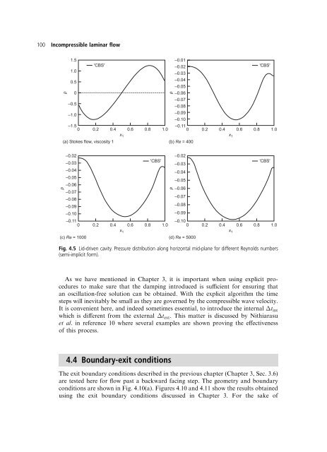
- Page 111: 98 Incompressible laminar ¯ow The
- Page 115 and 116: 102 Incompressible laminar ¯ow p 1
- Page 117 and 118: 104 Incompressible laminar ¯ow �
- Page 119 and 120: 106 Incompressible laminar ¯ow x 2
- Page 121 and 122: 108 Incompressible laminar ¯ow Thi
- Page 123 and 124: 110 Incompressible laminar ¯ow 4.5
- Page 125 and 126: 112 Incompressible laminar ¯ow 4.5
- Page 127 and 128: 114 Incompressible laminar ¯ow (a)
- Page 129 and 130: 116 Incompressible laminar ¯ow (b)
- Page 131 and 132: 118 Incompressible laminar ¯ow wit
- Page 133 and 134: 120 Incompressible laminar ¯ow The
- Page 135 and 136: 122 Incompressible laminar ¯ow Fig
- Page 137 and 138: 124 Incompressible laminar ¯ow and
- Page 139 and 140: 126 Incompressible laminar ¯ow U U
- Page 141 and 142: 128 Incompressible laminar ¯ow C L
- Page 143 and 144: 130 Incompressible laminar ¯ow are
- Page 145 and 146: 132 Incompressible laminar ¯ow sha
- Page 147 and 148: 134 Incompressible laminar ¯ow Fig
- Page 149 and 150: 136 Incompressible laminar ¯ow 28.
- Page 151 and 152: 138 Incompressible laminar ¯ow 71.
- Page 153 and 154: 140 Incompressible laminar ¯ow 114
- Page 155 and 156: 142 Incompressible laminar ¯ow 153
- Page 157 and 158: 144 Free surfaces, buoyancy and tur
- Page 159 and 160: 146 Free surfaces, buoyancy and tur
- Page 161 and 162: 148 Free surfaces, buoyancy and tur
- Page 163 and 164:
150 Free surfaces, buoyancy and tur
- Page 165 and 166:
152 Free surfaces, buoyancy and tur
- Page 167 and 168:
154 Free surfaces, buoyancy and tur
- Page 169 and 170:
156 Free surfaces, buoyancy and tur
- Page 171 and 172:
158 Free surfaces, buoyancy and tur
- Page 173 and 174:
160 Free surfaces, buoyancy and tur
- Page 175 and 176:
162 Free surfaces, buoyancy and tur
- Page 177 and 178:
164 Free surfaces, buoyancy and tur
- Page 179 and 180:
166 Free surfaces, buoyancy and tur
- Page 181 and 182:
168 Free surfaces, buoyancy and tur
- Page 183 and 184:
170 Compressible high-speed gas ¯o
- Page 185 and 186:
172 Compressible high-speed gas ¯o
- Page 187 and 188:
174 Compressible high-speed gas ¯o
- Page 189 and 190:
176 Compressible high-speed gas ¯o
- Page 191 and 192:
178 Compressible high-speed gas ¯o
- Page 193 and 194:
180 Compressible high-speed gas ¯o
- Page 195 and 196:
182 Compressible high-speed gas ¯o
- Page 197 and 198:
184 Compressible high-speed gas ¯o
- Page 199 and 200:
186 Compressible high-speed gas ¯o
- Page 201 and 202:
188 Compressible high-speed gas ¯o
- Page 203 and 204:
190 Compressible high-speed gas ¯o
- Page 205 and 206:
192 Compressible high-speed gas ¯o
- Page 207 and 208:
194 Compressible high-speed gas ¯o
- Page 209 and 210:
196 Compressible high-speed gas ¯o
- Page 211 and 212:
198 Compressible high-speed gas ¯o
- Page 213 and 214:
200 Compressible high-speed gas ¯o
- Page 215 and 216:
202 Compressible high-speed gas ¯o
- Page 217 and 218:
204 Compressible high-speed gas ¯o
- Page 219 and 220:
206 Compressible high-speed gas ¯o
- Page 221 and 222:
208 Compressible high-speed gas ¯o
- Page 223 and 224:
210 Compressible high-speed gas ¯o
- Page 225 and 226:
212 Compressible high-speed gas ¯o
- Page 227 and 228:
214 Compressible high-speed gas ¯o
- Page 229 and 230:
216 Compressible high-speed gas ¯o
- Page 231 and 232:
7 Shallow-water problems 7.1 Introd
- Page 233 and 234:
220 Shallow-water problems reduced
- Page 235 and 236:
222 Shallow-water problems Approxim
- Page 237 and 238:
224 Shallow-water problems These si
- Page 239 and 240:
226 Shallow-water problems h = 2 η
- Page 241 and 242:
228 Shallow-water problems Surface
- Page 243 and 244:
230 Shallow-water problems FL: 578
- Page 245 and 246:
232 Shallow-water problems B Fig. 7
- Page 247 and 248:
234 Shallow-water problems Time = 0
- Page 249 and 250:
236 Shallow-water problems Fig. 7.1
- Page 251 and 252:
238 Shallow-water problems where no
- Page 253 and 254:
240 Shallow-water problems 14. T.D.
- Page 255 and 256:
8 Waves Peter Bettess 8.1 Introduct
- Page 257 and 258:
244 Waves the familiar form where
- Page 259 and 260:
246 Waves of 10 nodes or thereabout
- Page 261 and 262:
248 Waves and the Astley wave envel
- Page 263 and 264:
250 Waves agreement with the analyt
- Page 265 and 266:
252 Waves Fig. 8.3 General wave dom
- Page 267 and 268:
254 Waves Relative errors (%) 10 8
- Page 269 and 270:
256 Waves (The indirect boundary in
- Page 271 and 272:
258 Waves where m is the number of
- Page 273 and 274:
260 Waves Fig. 17.6 of Volume 1. La
- Page 275 and 276:
262 Waves to using such coordinate
- Page 277 and 278:
264 Waves r/a 5 4 3 2 1 0 0 2 4 6 8
- Page 279 and 280:
266 Waves 8.16 Three-dimensional ef
- Page 281 and 282:
268 Waves wave elevations in shallo
- Page 283 and 284:
270 Waves integrals. Preliminary re
- Page 285 and 286:
272 Waves 39. R.J. Astley. FE mode
- Page 287 and 288:
9 Computer implementation of the CB
- Page 289 and 290:
276 Computer implementation of the
- Page 291 and 292:
278 Computer implementation of the
- Page 293 and 294:
280 Computer implementation of the
- Page 295 and 296:
282 Computer implementation of the
- Page 297 and 298:
284 Computer implementation of the
- Page 299 and 300:
286 Computer implementation of the
- Page 301 and 302:
288 Computer implementation of the
- Page 303 and 304:
290 Computer implementation of the
- Page 305 and 306:
292 Appendix A Again substituting t
- Page 307 and 308:
294 Appendix B As usual the domain
- Page 309 and 310:
296 Appendix B 5. While the piecewi
- Page 311 and 312:
Appendix C Edge-based ®nite elemen
- Page 313 and 314:
Appendix D Multigrid methods It is
- Page 315 and 316:
Appendix E Boundary layer±inviscid
- Page 317 and 318:
304 Appendix E In Fig. E.2, Cp is t
- Page 320 and 321:
Author index Page numbers in bold r
- Page 322 and 323:
Gerdes, K. 259, 264, 265, 272 Ghia,
- Page 324 and 325:
Nakos, D.E. 146, 165 Narayana, P.A.
- Page 326:
Wu, J. 67, 90; 102, 108, 112, 137;
- Page 329 and 330:
316 Subject index Blurring of the s
- Page 331 and 332:
318 Subject index Convected coordin
- Page 333 and 334:
320 Subject index Elements ± cont.
- Page 335 and 336:
322 Subject index Flows: buoyancy d
- Page 337 and 338:
324 Subject index Incompressible St
- Page 339 and 340:
326 Subject index Metals: hot, 120
- Page 341 and 342:
328 Subject index Prescribed tracti
- Page 343 and 344:
330 Subject index Shock interaction
- Page 345 and 346:
332 Subject index Theorem ± cont.
- Page 347:
334 Subject index Wave ± cont. ste