The Use and Calibration of the Kern ME5000 Mekometer - SLAC ...
The Use and Calibration of the Kern ME5000 Mekometer - SLAC ...
The Use and Calibration of the Kern ME5000 Mekometer - SLAC ...

Create successful ePaper yourself
Turn your PDF publications into a flip-book with our unique Google optimized e-Paper software.
I<br />
--<br />
-<br />
:<br />
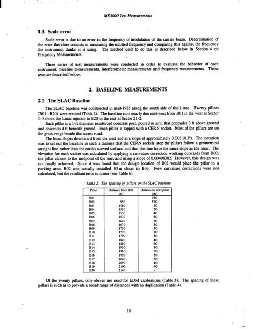
1.3. Scale error<br />
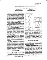
<strong>ME5000</strong> Test Measurements<br />
Scale error is due to an error in <strong>the</strong> frequency <strong>of</strong> modulation <strong>of</strong> <strong>the</strong> carrier beam. Determination <strong>of</strong><br />
<strong>the</strong> error <strong>the</strong>refore consists in measuring <strong>the</strong> emitted Bequency <strong>and</strong> comparing this against <strong>the</strong> frequency<br />
<strong>the</strong> instrument thinks it is using. <strong>The</strong> method used to do this is described below in Section 4 on<br />
Frequency Measurements.<br />
Three series <strong>of</strong> test measurements were conducted in order to evaluate <strong>the</strong> behavior <strong>of</strong> each<br />
instrument: baseline measurements, interferometer measurements <strong>and</strong> frequency measurements. <strong>The</strong>se<br />
tests am described below.<br />
2.1. <strong>The</strong> <strong>SLAC</strong> Baseline<br />
2. BASELINE MEASUREMENTS<br />
<strong>The</strong> <strong>SLAC</strong> baseline was constructed in mid-1985 along <strong>the</strong> south side <strong>of</strong> <strong>the</strong> Linac. Twenty pillars<br />
(BOl - B20) were erected (Table 2). <strong>The</strong> baseline runs nearly due east-west from BOl in <strong>the</strong> west at Sector<br />
O-O above <strong>the</strong> Linac injector to B20 in <strong>the</strong> east at Sector 21-2.<br />
Each pillar is a 1-ft diameter reinforced concrete post, poured in situ, that protrudes 3 ft above ground<br />
<strong>and</strong> descends 4 ft beneath ground. Each pillar is topped with a CERN socket. Most <strong>of</strong> <strong>the</strong> pillars are on<br />
<strong>the</strong> grass verge beside <strong>the</strong> access road.<br />
<strong>The</strong> linac slopes downward from <strong>the</strong> west end at a slope <strong>of</strong> approximately 0.005 (0.3”). <strong>The</strong> intention<br />
was to set out <strong>the</strong> baseline in such a manner that <strong>the</strong> CERN sockets atop <strong>the</strong> pillars follow a geometrical<br />
straight line ra<strong>the</strong>r than <strong>the</strong> earth’s curved surface, <strong>and</strong> that this line have <strong>the</strong> same slope as <strong>the</strong> linac. <strong>The</strong><br />
elevation for each socket was calculated by applying a curvature correction working outwards from B02,<br />
<strong>the</strong> $llar closest to <strong>the</strong> midpoint <strong>of</strong> <strong>the</strong> line, <strong>and</strong> using a slope <strong>of</strong> 0.00498382. However, this design was<br />
not finally achieved. Since it was found that <strong>the</strong> design location <strong>of</strong> B02 would place <strong>the</strong> pillar in a<br />
parking area, B02 was actually installed 10m closer to B03. New curvature corrections were not<br />
calculated, but <strong>the</strong> resultant error is minor (see Table 6).<br />
TABLE 2. <strong>The</strong> spacing <strong>of</strong> pillars on <strong>the</strong> <strong>SLAC</strong> baseline<br />
Pilh<br />
BOl<br />
B02<br />
B03<br />
B04<br />
B05<br />
B06<br />
B07<br />
B08<br />
B09<br />
BlO<br />
Bll<br />
B12<br />
B13<br />
B14<br />
B15<br />
B16<br />
B17<br />
B18<br />
B19<br />
B20<br />
Distaace from BOl<br />
(m)<br />
950<br />
1480<br />
1510<br />
1530<br />
1570<br />
1620<br />
1670<br />
1720<br />
1770<br />
1790<br />
1840<br />
1880<br />
1930<br />
1960<br />
1990<br />
2040<br />
2090<br />
2100<br />
2140<br />
Distance to next pillar<br />
(m)<br />
950<br />
530<br />
30<br />
20<br />
40<br />
50<br />
50<br />
50<br />
50<br />
20<br />
50<br />
40<br />
50<br />
30<br />
30<br />
50<br />
50<br />
10<br />
40<br />
Of <strong>the</strong> twenty pillars, only eleven are used for EDM calibrations (Table 3). <strong>The</strong> spacing <strong>of</strong> <strong>the</strong>se<br />
pillars is such as to provide a broad range <strong>of</strong> distances with no duplication (Table 4).<br />
18