

RACCORDI OLEOIDRAULICI PER TUBI IN ACCIAIO E - Eurotim
RACCORDI OLEOIDRAULICI PER TUBI IN ACCIAIO E - Eurotim
RACCORDI OLEOIDRAULICI PER TUBI IN ACCIAIO E - Eurotim

Create successful ePaper yourself
Turn your PDF publications into a flip-book with our unique Google optimized e-Paper software.
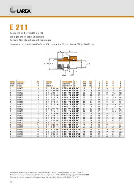
E 211<br />
Raccordi di Estremità diritti<br />
Straight Male Stud Couplings<br />
Gerade Einschraubverschraubungen<br />
Filettatura BSP cilindrica (D<strong>IN</strong> ISO 228) - Thread: BSP cylindrical (D<strong>IN</strong> ISO 228) - Gewinde: BSP zyl. (D<strong>IN</strong> ISO 228)<br />
SERIE Pressione Ø T CODICE DESCRIZIONE Ø F CH1 CH2 a d3 L1 l1<br />
Series Pressure ø T Part n° Description ø F Ch1 Ch2 a d3 L1 l1<br />
Reihe Druck ø T Bestell. nr. Bestellzeichen ø F Ch1 Ch2 a d3 L1 I1<br />
S PN 400 6 E 211 9 106 000 E 211 - 106 S G 1/4” 19 17 12 18 28 13<br />
S PN 400 8 E 211 9 108 000 E 211 - 108 S G 1/4” 19 19 12 18 30 15<br />
S PN 400 8 E 211 9 108 110 E 211 - 108 S G 3/8” 22 19 12 22 30,5 15,5<br />
S PN 400 10 E 211 9 110 000 E 211 - 110 S G 3/8” 22 22 12 22 31 15<br />
S PN 400 10 E 211 9 110 106 E 211 - 110 S G 1/4” 22 22 12 18 30,5 14,5<br />
S PN 400 10 E 211 9 110 113 E 211 - 110 S G 1/2” 27 22 14 26 33,5 17,5<br />
S PN 400 12 E 211 9 112 000 E 211 - 112 S G 3/8” 22 24 12 22 33 17<br />
S PN 400 12 E 211 9 112 106 E 211 - 112 S G 1/4” 22 24 12 18 32,5 16,5<br />
S PN 400 12 E 211 9 112 113 E 211 - 112 S G 1/2” 27 24 14 26 33,5 17,5<br />
S PN 400 14 E 211 9 114 000 E 211 - 114 S G 1/2” 27 27 14 26 37 19<br />
S PN 400 14 E 211 9 114 110 E 211 - 114 S G 3/8” 24 27 12 22 36,5 18,5<br />
S PN 400 16 E 211 9 116 000 E 211 - 116 S G 1/2” 27 30 14 26 37 18,5<br />
S PN 400 16 E 211 9 116 110 E 211 - 116 S G 3/8” 27 30 12 22 37 18,5<br />
S PN 400 16 E 211 9 116 119 E 211 - 116 S G 3/4” 32 30 16 32 39 20,5<br />
S PN 400 20 E 211 9 120 000 E 211 - 120 S G 3/4” 32 36 16 32 42 20,5<br />
S PN 400 20 E 211 9 120 113 E 211 - 120 S G 1/2” 32 36 14 26 42 20,5<br />
S PN 250 25 E 211 9 125 000 E 211 - 125 S G 1” 41 46 18 39 47 23<br />
S PN 250 25 E 211 9 125 119 E 211 - 125 S G 3/4” 41 46 16 32 47 23<br />
S PN 160 30 E 211 9 130 000 E 211 - 130 S G 1”1/4 50 50 20 49 50 23,5<br />
S PN 160 30 E 211 9 130 125 E 211 - 130 S G 1” 46 50 18 39 50 23,5<br />
S PN 160 38 E 211 9 138 000 E 211 - 138 S G 1”1/2 55 60 22 55 57 26<br />
S PN 160 38 E 211 9 138 132 E 211 - 138 S G 1”1/4 55 60 20 49 57 26<br />
Temperature di utilizzo senza riduzione di pressione: da -40° a +120°C. Spigolo di tenuta D<strong>IN</strong> 3852 forma “B”.<br />
Permissible working temperatures without reductions in pressure: -40° to +120°C. Sealing edge form “B” D<strong>IN</strong> 3852.<br />
Zulässige Betriebstemperatur ohne Druckabschläge: -40° bis +120°C. Dichtkante D<strong>IN</strong> 3852 Form “B”.<br />
52