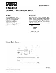
LM4702 Audio Power Amplifier Series Stereo High Fidelity 200 Volt ...
LM4702 Audio Power Amplifier Series Stereo High Fidelity 200 Volt ...
LM4702 Audio Power Amplifier Series Stereo High Fidelity 200 Volt ...

You also want an ePaper? Increase the reach of your titles
YUMPU automatically turns print PDFs into web optimized ePapers that Google loves.
<strong>LM4702</strong><br />
Electrical Characteristics (<strong>LM4702</strong>A) Vcc = +100V, Vee = –100V<br />
(Pre-release information) (Notes 1, 2)<br />
The following specifications apply for IMUTE = 1.5mA, Figure 1, unless otherwise specified. Limits apply for TA = 25˚C.<br />
Symbol Parameter Conditions <strong>LM4702</strong> Units<br />
Typical Limit (Limits)<br />
(Note 6) (Notes 7, 8)<br />
Total Quiescent <strong>Power</strong> Supply<br />
Current<br />
VCM = 0V, VO = 0V, IO = 0A 27 TBD mA (max)<br />
I CC<br />
THD+N<br />
Total Harmonic Distortion +<br />
Noise<br />
No load, A V = 30dB<br />
V OUT = 20V RMS<br />
f = 1kHz 0.001 TBD<br />
f = 10kHz TBD TBD % (max)<br />
f = 100Hz TBD TBD<br />
RS Input Bias Resistor 50 TBD kΩ (max)<br />
Av Closed Loop <strong>Volt</strong>age Gain TBD dB (min)<br />
Av open Open Loop Gain Vin = 1mVrms, f = 1KHz, C = 30pF 93 dB<br />
Vom Output <strong>Volt</strong>age Swing THD = 0.05%, Freq = 20Hz to 20KHz 57 TBD Vrms (min)<br />
Vnoise Output Noise<br />
Rs = 10kΩ, LPF = 30kHz, Av = 30dB<br />
A-weighted<br />
I OUT Output Current Outputs Shorted 5.5<br />
I mute<br />
X TALK<br />
Current into Mute Pin<br />
Channel Separation (Note 11)<br />
To put part in “play” mode<br />
100<br />
80<br />
1.5<br />
TBD<br />
TBD<br />
TBD<br />
TBD<br />
TBD<br />
TBD<br />
Av = 30dB<br />
f = 1kHz 90 TBD<br />
f = 10kHz TBD TBD<br />
f = 100Hz TBD TBD<br />
µV (max)<br />
mA(min)<br />
mA (max)<br />
mA(min)<br />
mA (max)<br />
dB (min)<br />
SR Slew Rate<br />
VIN = 1.2VP-P, f = 10kHz square Wave,<br />
Outputs shorted<br />
TBD TBD V/µs (min)<br />
VOS Input Offset <strong>Volt</strong>age VCM = 0V, IO = 0mA 5 TBD mV (max)<br />
IB Input Bias Current VCM = 0V, IO = 0mA 150 TBD nA (max)<br />
PSRR <strong>Power</strong> Supply Rejection Ratio<br />
IMD Intermodulation Distortion<br />
Rs = 1k, f = 100Hz,<br />
Vripple = 1Vrms, Input Referred<br />
at 20kHz / 19kHz<br />
at 60Hz / 7kHz<br />
110 TBD dB (min)<br />
TBD TBD dB<br />
Note 1: All voltages are measured with respect to the ground pins, unless otherwise specified.<br />
Note 2: Absolute Maximum Ratings indicate limits beyond which damage to the device may occur. Operating Ratings indicate conditions for which the device is<br />
functional, but do not guarantee specific performance limits. Electrical Characteristics state DC and AC electrical specifications under particular test condition which<br />
guarantee specific performance limits. This assumes that the device is within the Operating Ratings. Specifications are not guaranteed for parameters where no limit<br />
is given. However, the typical value is a good indication of device’s performance.<br />
Note 3: The maximum power dissipation must be de-rated at elevated temperatures and is dictated by TJMAX, θJC, and the ambient temperature TA. The maximum<br />
allowable power dissipation is PDMAX =(TJMAX -TA)/θJC or the number given in the Absolute Maximum Ratings, whichever is lower. For the <strong>LM4702</strong>, TJMAX = 150˚C<br />
and the typical θJC is 1˚C/W. Refer to the Thermal Considerations section for more information.<br />
Note 4: Human body model, 100pF discharged through a 1.5kΩ resistor.<br />
Note 5: Machine Model: a 220pF - 240pF discharged through all pins.<br />
Note 6: Typical specifications are measured at 25˚C and represent the parametric norm.<br />
Note 7: Tested limits are guaranteed to National’s AOQL (Average Outgoing Quality Level).<br />
Note 8: Datasheet min/max specification limits are guaranteed by design, test, or statistical analysis.<br />
Note 9: The maximum operating junction temperature is 150˚C.<br />
Note 10: PCB layout will affect cross talk. It is recommended that input and output traces be separated by as much distance as possible. Return ground traces from<br />
outputs should be independent back to a single ground point and use as wide of traces as possible.<br />
Note 11: The TA15A is a non-isolated package. The package’s metal back and any heat sink to which it is mounted are connected to the Vee potential when using<br />
only thermal compound. If a mica washer is used in addition to thermal compound, θCS (case to sink) is increased, but the heat sink will be electrically isolated from<br />
Vee.<br />
www.national.com 6