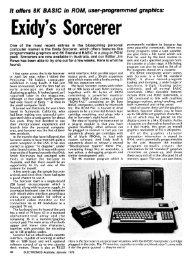
The Signetics 2650 - The MESSUI Place
The Signetics 2650 - The MESSUI Place
The Signetics 2650 - The MESSUI Place

You also want an ePaper? Increase the reach of your titles
YUMPU automatically turns print PDFs into web optimized ePapers that Google loves.
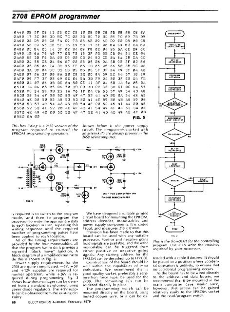
2708 EPROM programmer<br />
0440 OS OF 08 l3 03 00 08 10 08 013 08 OD 08 08 08 0A<br />
0 45 0 17 3C 00 3D BC 7C 00 3D BC 7D BC 08 7C 09 7111 D9<br />
0 460 02 D8 00 08 74 C9 73 08 6E 09 6D D9 02 DB 00 CS<br />
0 47 0 66 C9 65 ES 5E 16 E9 50 17 3F 00 BA C9 83 CA 8A<br />
0 480 00 84 25 14 3F 02 134 09 FS OE 04 26 DA 6E D9 6C<br />
0 490 18 6A 76 40 77 02 75 18 3F 02 DB CD 04 51 CE 04<br />
04140 52 33 F6 DA 02 D9 00 CD 04 53 CE 04 54 32 EA CD<br />
0 4130 04 55 CE 04 56 07 00 05 05 06 2A 32 96 3F 02 86<br />
0 400 05 05 06 74 38 95 FF 05 1B 05 05 06 50 3B SC 06<br />
0 4D0 3A 3F 04 BC 39 ES 05 05 06 SF 3F 04 79 3F 04 40<br />
04E0 07 06 3F 00 BA 2 0 06 32 00 84 59 EC 84 57 18 19<br />
04F0 09 F7 3F 02 69 0D 04 5A 3B F9 04 20 3F 02 24 FB<br />
0500 04 07 06 32 DE 04 80 C8 II 3F 04 52 1 A 5A 013 OA<br />
0510 IA 06 05 05 06 70 32 C3 92 22 8 0 32 C 1 00 84 57<br />
0 520 CC 84 59 32 ES 1 A 76 IF 04 C6 53 57 49 54 43 48<br />
0 530 20 54 4F 2 0 50 52 4F 47 52 41 4D OD OA 54 46 45<br />
0 540 46 20 50 52 45 53 53 20 41 46 59 20 4B 45 59 00<br />
0 550 53 57 49 54 43 48 20 54 4F 20 52 45 41 44 00 45<br />
0 560 52 52 4F 52 20 40 4F 43 41 54 49 4F 46 53 3A 00<br />
057 0 4E 49 4C 00 50 52 4F 47 52 41 4D 4D 49 46 47 OD<br />
0 53 0 OA 00 FIG. 5<br />
This hex listing is a <strong>2650</strong> version of the<br />
program required to control the<br />
EPROM programming operation.<br />
1000<br />
25VW<br />
is required is to switch to the program<br />
mode, and then to program the<br />
processor to write the appropriate data<br />
to each location in turn, repeating this<br />
writing sequence until the required<br />
number of programming pulses have<br />
been applied to each location.<br />
All of the timing requirements are<br />
provided by the four monostables, all<br />
that the program has to do is provide a<br />
repeated "block move" function. A<br />
block diagram of a simplified routine to<br />
do this is shown in Fig. 2.<br />
Power supply requirements for the<br />
2708 are quite complicated. —5V, +5V<br />
and +12V supplies are required for<br />
normal operation, while +26V is required<br />
during programming. Fig. 3<br />
shows how these voltages can be derived<br />
from a standard transformer, using<br />
zener diode regulators. <strong>The</strong> +5V supply<br />
can be obtained from the existing circuitry.<br />
86<br />
ELECTRONICS Australia, February, 1979<br />
Shown below is the power supply<br />
circuit. <strong>The</strong> components marked with<br />
an asterisk (') are already present in the<br />
<strong>2650</strong> Minicomputer.<br />
aan VA<br />
(N) = PCB CONNECTION PIN<br />
• IN 2150 MINICOMPUTER<br />
26V<br />
+12V<br />
We have designed a suitable printed<br />
circuit board for mounting the EPROM,<br />
address decoder, monostables and<br />
power supply components. It is coded<br />
79upl, and measures 218 x 81mm.<br />
Provision has been made so that this<br />
board can be used with any suitable<br />
processor. Positive and negative going<br />
hold signals are available, and the write<br />
monostable can be triggered from<br />
either positive or negative going<br />
signals. Any starting address for the<br />
EPROM can be decoded, up to H7C00.<br />
Construction of the board should be<br />
well within the capabilities of most<br />
enthusiasts. We recommend that a<br />
good quality socket, preferably a zeroinsertion<br />
force type, be used for the<br />
2708. <strong>The</strong> remaining ICs can be<br />
soldered directly in place.<br />
<strong>The</strong> programming switch can be<br />
mounted directly on the board, using<br />
tinned copper wire, or it can be ex-<br />
PROM PROG<br />
INITIALISE<br />
LOOP COUNTER<br />
SE UP<br />
ADOR SEES<br />
PROGRAM<br />
LOC TION<br />
MGR MENT<br />
AODR SSES<br />
DECREMENT<br />
LOOP COUNTER<br />
SET UP<br />
ADDRESSES<br />
NCR MENT<br />
ADDRESSES<br />
TOP<br />
FIG. 2<br />
This is the flowchart for the controlling<br />
program. Use it to write the routines<br />
required by your processor.<br />
tended with a cable if desired. It should<br />
be placed in a position where accidental<br />
operation is unlikely, to ensure that<br />
no accidental programming occurs.<br />
As the board has to be wired directly<br />
to the address and data busses, we<br />
recommend that it be mounted in the<br />
main computer case. Make sure,<br />
however, that access can be gained<br />
relatively easily to the EPROM socket<br />
and the read/program switch.<br />
NO<br />
PRINT<br />
ADDRESS