- Page 1 and 2:
Multicam Digital Surveillance Syste
- Page 3 and 4:
Full Manual for V8.4 GeoVision Surv
- Page 5 and 6:
iv 1.5.5 Setting Double Password fo
- Page 7 and 8:
vi 3.3.2 Tracking in PIP View......
- Page 9 and 10:
viii 4.12 Specifications ..........
- Page 11 and 12:
x 8.2.3 Video Settings ............
- Page 13 and 14:
xii 9.4.4 Viewing Host Information
- Page 15 and 16:
xiv 11.9.6 Retrieving Recorded File
- Page 17 and 18:
Chapter 1 Configuring Main System .
- Page 19 and 20:
1.16 Picture-and-Picture View .....
- Page 21 and 22:
Allow removing password System: It
- Page 23 and 24:
11 Network Enables the connection t
- Page 25 and 26:
1.1.3 Playing Back Video You can in
- Page 27 and 28:
1.2.1 Configuring Global Recording
- Page 29 and 30:
4. To switch between the mini and n
- Page 31 and 32:
Pre-recording duration = Total Fram
- Page 33 and 34:
1.2.2 Setting Data Storage You can
- Page 35 and 36:
Note: 1 Configuring Main System 1.
- Page 37 and 38:
Resolution Button: This button is o
- Page 39 and 40:
Output Module: Triggers the specifi
- Page 41 and 42:
1.2.5 Geo Mpeg4 Advanced Settings 1
- Page 43 and 44:
1.2.6 Selecting Screen Layout This
- Page 45 and 46:
1.2.8 Installing Cameras and Audios
- Page 47 and 48:
1.2.10 Setting Text Overlay You can
- Page 49 and 50:
1.3.2 Fixing Aspect Ratio This feat
- Page 51 and 52:
In the Auto Gain Control window, cl
- Page 53 and 54:
1 Configuring Main System [WebCam,
- Page 55 and 56:
1.3.5 Hard Disk Calculator 1 Config
- Page 57 and 58:
1.3.6 Turbo Mode Turbo mode allows
- Page 59 and 60:
1.4 Camera Monitoring Click the Mon
- Page 61 and 62:
1.4.3 Daylight Saving Time Recordin
- Page 63 and 64:
1.5 Account and Password The passwo
- Page 65 and 66:
Force Password change at the first
- Page 67 and 68:
1.5.3 Retrieving Password Through E
- Page 69 and 70:
1.5.5 Setting Double Password for V
- Page 71 and 72:
1.6.2 Auto Login User without Acces
- Page 73 and 74:
1.7 System Log System Log provides
- Page 75 and 76:
IO Monitor Start / Stop: Appears wh
- Page 77 and 78:
[POS] This function shows the POS e
- Page 79 and 80:
[Default Video Player] Monitor Tab
- Page 81 and 82:
1.8 Recording Schedule You can prog
- Page 83 and 84:
1.8.2 Special Days Schedule 1. Clic
- Page 85 and 86:
1.8.4 Center V2 Schedule 1 Configur
- Page 87 and 88:
2. Click Add schedule. This dialog
- Page 89 and 90:
Viewing Compacted Video Files After
- Page 91 and 92:
3. In the Task Name field, name the
- Page 93 and 94:
1.9.3 Setting Backup Schedule You c
- Page 95 and 96:
1.10 Hotline Notification When even
- Page 97 and 98:
d. Select PCM 8,000 Hz, 8-bit Mono,
- Page 99 and 100:
5. Start monitoring. When the speci
- Page 101 and 102:
E-Mail To: Type recipients’ e-mai
- Page 103 and 104:
1.12 PTZ Control 1 Configuring Main
- Page 105 and 106:
1.12.1 Mapping PTZ Cameras This opt
- Page 107 and 108:
1. Select Tour Schedule on the Came
- Page 109 and 110:
1.12.4 PTZ Automation Other than th
- Page 111 and 112:
1.14 Video Noise Solutions The syst
- Page 113 and 114:
1.14.2 Noise Detection to Reduce Fi
- Page 115 and 116:
1.15 Picture-in-Picture View With t
- Page 117 and 118:
1.17 Fisheye View A fisheye camera
- Page 119 and 120:
Setting up a Third-Party Fisheye Ca
- Page 121 and 122:
1.18 Shortcuts You can create up to
- Page 123 and 124:
1.19.2 Touch Screen Panel The touch
- Page 125 and 126:
1.20 System Tools 1.20.1 Colorful M
- Page 127 and 128:
1.20.2 Image Quality of DirectDraw
- Page 129 and 130:
1.20.4 Deactivating Video Lost Beep
- Page 131 and 132:
1.20.6 Fast Key Reference This opti
- Page 133 and 134:
1.20.8 Version Information To know
- Page 135 and 136:
Hybrid and NVR Solution To implemen
- Page 137 and 138:
2.3 Hybrid Solution Description 2 H
- Page 139 and 140:
2.5 IP Channel Setup The setup proc
- Page 141 and 142:
6. Click Apply. The IP camera is ad
- Page 143 and 144:
2 Hybrid and NVR Solution [Image Or
- Page 145 and 146:
2.7 RTSP Connection You can add an
- Page 147 and 148:
2.8 ONVIF & PSIA Connection The GV-
- Page 149 and 150:
5. Repeat steps 3 and 4 to map more
- Page 151 and 152:
5. Under the Economic Frame Rate Se
- Page 153 and 154:
2.11 On Demand Display 2 Hybrid and
- Page 155 and 156:
Chapter 3 Video Analysis...........
- Page 157 and 158:
Video Analysis 3.1 Object Tracking
- Page 159 and 160:
[Setup] Pan, Tilt and Zoom: Use th
- Page 161 and 162:
Starting Object Tracking After the
- Page 163 and 164:
3.1.2 Object Zooming If only one PT
- Page 165 and 166:
Starting Object Zooming After the a
- Page 167 and 168:
Setting up Advanced Single Camera T
- Page 169 and 170:
3.3 Digital Object Tracking Without
- Page 171 and 172:
3.3.2 Tracking in PIP View The PIP
- Page 173 and 174:
3.4 Object Counting and Intrusion A
- Page 175 and 176:
3. To test your counting settings,
- Page 177 and 178:
6. To activate the function at cert
- Page 179 and 180:
4. Select one camera from the drop-
- Page 181 and 182:
3.5.3 Searching Object Index You ca
- Page 183 and 184:
3.6 Automatic Video Snapshots The V
- Page 185 and 186:
3.6.2 Searching Video Snapshots You
- Page 187 and 188:
3.7 Face Detection The Face Detecti
- Page 189 and 190:
3.8.2 Setting Face Count 1. Click t
- Page 191 and 192:
Output Module: Activates the output
- Page 193 and 194:
Figure 3-32 Object Monitor 5. In th
- Page 195 and 196:
Other Controls in the Video Object
- Page 197 and 198:
3.10 Privacy Mask Protection The Pr
- Page 199 and 200:
3.11 Scene Change Detection The Sce
- Page 201 and 202:
3.12 Panorama View Spliced from mul
- Page 203 and 204:
3. From the Reference drop-down lis
- Page 205 and 206:
3.13 Video Defogging Smoky environm
- Page 207 and 208:
3.15 Advanced Motion Detection To a
- Page 209 and 210:
3.16 Crowd Detection Crowd detectio
- Page 211 and 212:
Note: For the Skip Instant Light Ch
- Page 213 and 214:
Tolerance Time of Alarm: Sets the d
- Page 215 and 216:
3.18 Advanced Unattended Object Det
- Page 217 and 218:
14. Start monitoring to run the app
- Page 219 and 220:
5. Select Sensitivity. The higher t
- Page 221 and 222:
3.20 Video Analysis Schedule A sche
- Page 223 and 224:
3.21 Specifications Feature Notes P
- Page 225 and 226:
Chapter 4 Video Playback ..........
- Page 227 and 228:
Video Playback Recorded files can b
- Page 229 and 230:
The controls in the ViewLog window:
- Page 231 and 232:
4.1.1 Playback Screen Layout 4 Play
- Page 233 and 234:
4.1.2 Playback Control Buttons Vide
- Page 235 and 236:
4.1.3 Bookmarking a Frame 4 Playing
- Page 237 and 238:
4.1.4 Searching a Video Event 4 Pla
- Page 239 and 240:
List Mode and Line Mode 4 Playing B
- Page 241 and 242:
Setting up the MDB filter: 1. Click
- Page 243 and 244:
5. If the video event has the Priva
- Page 245 and 246:
[Set Location] Click the […] butt
- Page 247 and 248:
4.1.7 Saving Images You can save th
- Page 249 and 250:
4.1.9 Recycling Option for Video Fi
- Page 251 and 252:
4 Playing Back Video Files [Multi V
- Page 253 and 254:
[Play Setting] Figure 4-23 [General
- Page 255 and 256:
4 Playing Back Video Files Using C
- Page 257 and 258:
4.2 Object Search 4 Playing Back Vi
- Page 259 and 260:
4.3 Advanced Log Browser 4 Playing
- Page 261 and 262:
4.3.1 Filter Settings You can defin
- Page 263 and 264:
4.4 Quick Search Quick Search is a
- Page 265 and 266:
4.4.1 Event Query Settings Click th
- Page 267 and 268:
4.5 Address Book With Address Book,
- Page 269 and 270:
4.5.3 Creating a Folder Link 4 Play
- Page 271 and 272:
4.5.5 Importing and Exporting the A
- Page 273 and 274:
2. Click the Add button to bring up
- Page 275 and 276:
4.7.2 Retrieving Recordings from Mu
- Page 277 and 278:
4.7.4 Resuming Backup 4 Playing Bac
- Page 279 and 280:
To stop a connection, click the End
- Page 281 and 282:
4.8.2 Running Remote Playback Clien
- Page 283 and 284:
Disconnecting from RPB Server Click
- Page 285 and 286:
[Connection List] Indicates the num
- Page 287 and 288:
Preference Settings Figure 4-52 4 P
- Page 289 and 290: 4 Playing Back Video Files 7. Selec
- Page 291 and 292: 4.11 Fast Key Reference 4 Playing B
- Page 293 and 294: Backup, Deletion and Repair CHAPTER
- Page 295 and 296: 5.2 Backing Up Recorded Files Using
- Page 297 and 298: [Information] Database Files: Clic
- Page 299 and 300: 5 Backup, Deletion and Repair 2. Fo
- Page 301 and 302: 5.4 Deleting Recorded Files To dele
- Page 303 and 304: 5.5 Repairing Damaged File Paths 5
- Page 305 and 306: 5.6 Repairing Damaged Video Files 5
- Page 307 and 308: Chapter 6 I/O Applications.........
- Page 309 and 310: 6.1 I/O Device Setup To connect the
- Page 311 and 312: Output Module: Triggers the specifi
- Page 313 and 314: Following illustrations can help yo
- Page 315 and 316: 2. Input (N/O + Latch Trigger) + Ou
- Page 317 and 318: 6.3 Advanced I/O Applications In th
- Page 319 and 320: 6.3.2 Setting Momentary and Maintai
- Page 321 and 322: 6.3.4 Overlaying Input Name onto Sc
- Page 323 and 324: 6.4 Input State Detection This feat
- Page 325 and 326: 6.6 Advanced I/O Panel The Advanced
- Page 327 and 328: Editing a Group: To modify group se
- Page 329 and 330: 6.6.3 Configuring the Advanced I/O
- Page 331 and 332: Creating a Mode Schedule: Define th
- Page 333 and 334: 6.6.6 Forcing Output To manually fo
- Page 335 and 336: 6.6.8 System-Wide Triggers The Syst
- Page 337 and 338: 6.6.10 Managing a Group of I/O Devi
- Page 339: 6.7.2 Using Visual Automation 1. On
- Page 343 and 344: Point-Of-Sale (POS) Application CHA
- Page 345 and 346: Settings At the POS device: 7 Point
- Page 347 and 348: 7.1.2 Data Capture Box Integration
- Page 349 and 350: 5. Select POS Data Sender from Wind
- Page 351 and 352: 8. Click Start Service to send grap
- Page 353 and 354: 7 Point-of-Sale (POS) Application
- Page 355 and 356: 7 Point-of-Sale (POS) Application
- Page 357 and 358: 7 Point-of-Sale (POS) Application [
- Page 359 and 360: 7.6.1 Setting Alarm Frequency To el
- Page 361 and 362: 7.7 Codepage Mapping 7 Point-of-Sal
- Page 363 and 364: 7.9 POS Live View 7 Point-of-Sale (
- Page 365 and 366: 7.10 POS Color Text 7 Point-of-Sale
- Page 367 and 368: 7 Point-of-Sale (POS) Application 5
- Page 369 and 370: 8.6.2 Host List....................
- Page 371 and 372: 8.1 Remote Viewing Using a Web Brow
- Page 373 and 374: The following WebCam server feature
- Page 375 and 376: Note: When Enhance network security
- Page 377 and 378: 8.2.3 Video Settings Figure 8-6 Ma
- Page 379 and 380: 8.2.5 Audio Settings Connecting Aud
- Page 381 and 382: 8.2.6 JPG Settings These settings a
- Page 383 and 384: 8.2.8 Mobile Settings These setting
- Page 385 and 386: 8.2.10 UPnP Settings WebCam Server
- Page 387 and 388: Enabling UPnP on the WebCam Server
- Page 389 and 390: 8.2.12 Network Port Information The
- Page 391 and 392:
6 Change Camera Selects the desired
- Page 393 and 394:
8.3.2 Server List You can add the c
- Page 395 and 396:
8.3.4 Alarm Notification The Single
- Page 397 and 398:
There are three options for audio q
- Page 399 and 400:
8.3.7 PTZ Control Click the Camera
- Page 401 and 402:
8.3.9 I/O Control The new interface
- Page 403 and 404:
8.3.11 Picture-in-Picture View With
- Page 405 and 406:
8.3.13 Image Enhancement To enhance
- Page 407 and 408:
[Monitor] Enable I/O and Schedule m
- Page 409 and 410:
8.5 Multi-Window Viewer The Multi W
- Page 411 and 412:
The controls in the Multi View: Fig
- Page 413 and 414:
8.6.2 Host List The Host List displ
- Page 415 and 416:
8.6.4 Adding a Host The Multi View
- Page 417 and 418:
5. Click the Edit tab. This dialog
- Page 419 and 420:
8.6.7 Camera Polling To add cameras
- Page 421 and 422:
8.6.9 PTZ Control 1. Select a PTZ c
- Page 423 and 424:
8.6.11 Output Control 1. Click the
- Page 425 and 426:
8.6.13 System Configuration Click t
- Page 427 and 428:
8.6.14 Camera Status To show the ca
- Page 429 and 430:
8.6.16 Icon Image Change The icons
- Page 431 and 432:
Note: If you select different netwo
- Page 433 and 434:
8.7.3 Receiving Multicast and Audio
- Page 435 and 436:
8.8 JPEG Image Viewer JPEG Image Vi
- Page 437 and 438:
8.10 Remote ViewLog Through WebCam
- Page 439 and 440:
8. To export the search results, se
- Page 441 and 442:
8.13 Mobile Phone Applications With
- Page 443 and 444:
8.13.1 Windows PDA GV-GView V2 is a
- Page 445 and 446:
Playing Back the Recordings To play
- Page 447 and 448:
Accessing I/O Devices To access the
- Page 449 and 450:
Controlling PTZ Cameras To control
- Page 451 and 452:
8.13.2 Windows Smartphone With the
- Page 453 and 454:
4. Once the connection is establish
- Page 455 and 456:
8.13.3 Symbian Smartphone With the
- Page 457 and 458:
Playing Back the Recordings To play
- Page 459 and 460:
Forcing Outputs 1. To force any con
- Page 461 and 462:
4. On the camera list, click the de
- Page 463 and 464:
8.13.6 I-Mode Phone You can monitor
- Page 465 and 466:
8.13.7 iPhone GV-iView V2.1 functio
- Page 467 and 468:
Other Functions After you enlarge o
- Page 469 and 470:
My Favorite On the login screen (Fi
- Page 471 and 472:
8.13.8 Android Using the GV-AView V
- Page 473 and 474:
6. Tap the Connection button to con
- Page 475 and 476:
6. Press the menu button on the mob
- Page 477 and 478:
Chapter 9 E-Map Application .......
- Page 479 and 480:
9.1.1 The E-Map Editor Window 8 7 1
- Page 481 and 482:
6. To change the icons for I/O devi
- Page 483 and 484:
9.3 Starting E-Map After creating a
- Page 485 and 486:
9.4 Starting E-Map from a Remote Si
- Page 487 and 488:
9.4.2 Logging in Different Hosts Wh
- Page 489 and 490:
Main System. See Pop-up Live Video
- Page 491 and 492:
9.4.5 Accessing Remote ViewLog On t
- Page 493 and 494:
9.5.2 The E-Map Server Window Go to
- Page 495 and 496:
9.5.4 Remote Monitoring via E-Map S
- Page 497 and 498:
Chapter 10 Short Message Service...
- Page 499 and 500:
10.2 The SMS Server Window Run the
- Page 501 and 502:
10.3.2 Server Settings 10 Short Mes
- Page 503 and 504:
[Notify] Figure 10-5 Server Setting
- Page 505 and 506:
Creating a client: 1. Click the Add
- Page 507 and 508:
10.4.2 Viewing SMS Log Click the SM
- Page 509 and 510:
10.5 Password Security To prevent u
- Page 511 and 512:
Server IP: Enter the IP address of
- Page 513 and 514:
10.6.3 Setting Alert Notification T
- Page 515 and 516:
11.7.1 Installing the FBR Program .
- Page 517 and 518:
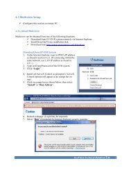
Useful Utilities This chapter discu
- Page 519 and 520:
11.1.2 Registering Domain Name with
- Page 521 and 522:
11.1.3 Starting Dynamic DNS After r
- Page 523 and 524:
11.1.4 Local DDNS Server The Local
- Page 525 and 526:
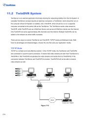
MultiCast Mode Multicast Network is
- Page 527 and 528:
11.2.2 Multicast Settings Figure 11
- Page 529 and 530:
11.2.4 Starting TwinDVR 1. Run Twin
- Page 531 and 532:
Starting WebCam Server at TwinDVR C
- Page 533 and 534:
11.3 Watermark Viewer The GV-System
- Page 535 and 536:
11.3.3 The Watermark Proof Window 1
- Page 537 and 538:
4. Run DMPOS. exe. This dialog box
- Page 539 and 540:
11.5.2 GV-Desktop Features The five
- Page 541 and 542:
[Desktop Type] Select Windows or GV
- Page 543 and 544:
11.6 Authentication Server The Auth
- Page 545 and 546:
11.6.3 Creating a Client DVR You mu
- Page 547 and 548:
11.6.5 Starting the Server To confi
- Page 549 and 550:
11.6.6 Connecting GV-System to the
- Page 551 and 552:
Note: When the disconnection icon a
- Page 553 and 554:
3. Click Tools on the menu bar, and
- Page 555 and 556:
11.7 Fast Backup and Restore With t
- Page 557 and 558:
11.7.3 Customizing the Features Not
- Page 559 and 560:
Restoring the System You can restor
- Page 561 and 562:
11.8.1 The Media Man Tool Window Th
- Page 563 and 564:
3 DVR Database Info Indicates the p
- Page 565 and 566:
11.8.4 Removing a Disk Drive To rem
- Page 567 and 568:
11.8.6 Setting Up LED Panel A LED p
- Page 569 and 570:
11.9 Backup Server The Backup Serve
- Page 571 and 572:
11.9.2 Enabling Backup Server Befor
- Page 573 and 574:
[Server Settings] You can select th
- Page 575 and 576:
11.9.4 Manually Adding Files for Ba
- Page 577 and 578:
[Backup File List] This tab display
- Page 579 and 580:
11.10 Backup Viewer With the Backup
- Page 581 and 582:
11.10.3 Performing Queries On the i
- Page 583 and 584:
Tools Text overlay’s camera name
- Page 585 and 586:
11.11 Bandwidth Control Application
- Page 587 and 588:
11.11.2 Allowing Remote Control at
- Page 589 and 590:
11.11.4 Controlling a WebCam Server
- Page 591 and 592:
11.11.6 Block List Setup Two types
- Page 593 and 594:
11.12 Report Generator With the Rep
- Page 595 and 596:
[Domain name from DDNS] This option
- Page 597 and 598:
Save to HD: Select this option to s
- Page 599 and 600:
11.12.4 E-Mail Attachment Settings
- Page 601 and 602:
4. Type the IP or domain name, ID a
- Page 603 and 604:
11.13 Spot Monitor Controller GV-Co
- Page 605 and 606:
[Video Setting] Figure 11-77 [Spot
- Page 607 and 608:
11.14 Quad Spot Monitor Controller
- Page 609 and 610:
[DIV 1-16] In the TV Quad Setting w
- Page 611 and 612:
11.14.3 Displaying TV Quad Panel On
- Page 613 and 614:
2. Click the Display list. If you d
- Page 615 and 616:
11.15.3 Setting Scanned Pages You c
- Page 617 and 618:
7. Start monitoring. When motion is
- Page 619 and 620:
11.15.6 Controlling Screen Display
- Page 621 and 622:
3. Select the COM Port the GPS rece
- Page 623 and 624:
11.16.3 Recording GPS Locations of
- Page 625 and 626:
Note: 1. If you like to use the map
- Page 627 and 628:
7. To create connection to other GV
- Page 629 and 630:
11.17 GV-IP Device Utility The IP D
- Page 631 and 632:
11.17.3 Setting up IP Devices 1. Do
- Page 633 and 634:
11.18 MCamCtrl Utility The MCamCtrl
- Page 635 and 636:
Troubleshooting Hardware 1. Message
- Page 637 and 638:
6. Can’t invoke hotline alerts.
- Page 639 and 640:
WebCam 1. A message "can't connect
- Page 641 and 642:
B. Supported PTZ Protocols and Mode
- Page 643 and 644:
C. Certified PTZ Models for Object
- Page 645 and 646:
E. Supported IP Device Brands Appen
- Page 647 and 648:
G. Custom Icon Naming Chart for Mul