Revista Tecno - ACM2 . Avalora Content Manager - Ohl
Revista Tecno - ACM2 . Avalora Content Manager - Ohl
Revista Tecno - ACM2 . Avalora Content Manager - Ohl

You also want an ePaper? Increase the reach of your titles
YUMPU automatically turns print PDFs into web optimized ePapers that Google loves.
38<br />
El líquido sale del tambor a través de las placas de rebosadero,<br />
que son ajustables para conseguir la separación<br />
óptima de líquidos y sólidos. Adicionalmente, se añaden<br />
floculantes químicos adaptados para eliminar partículas<br />
pequeñas de alrededor de 5µm.<br />
Los sólidos desecados podrán retirarse del emplazamiento<br />
sin requisitos de transportes especiales.<br />
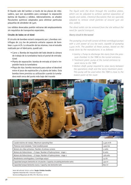
Circuito de lodos en el túnel<br />
El circuito de bombeo estará compuesto por 3 bombas centrífugas<br />
de 723 kw de potencia unitaria capaces de bombear<br />
2.400 m 3 /h. La situación de las mismas, tras el estudio<br />
realizado por el fabricante, quedó así:<br />
• Carro 1: Bomba de impulsión del lodo desde la cámara<br />
de trabajo de la tuneladora hacia el portal de entrada<br />
túnel<br />
• Planta de separación: bomba de entrada al túnel e impulsión<br />
hacia la tuneladora<br />
• Playa de vías: bomba necesaria para salvar el desnivel<br />
entre el pozo de explotación y la planta de lodos. Esta<br />
bomba tiene prevista su utilización cuando la tunela-<br />
dora esté cerca del punto más bajo del trazado<br />
Autor del artículo/ Article author: Sergio Córdoba González<br />
Ingeniero Industrial/ MSc Industrial Engineer<br />
Servicio de Maquinaria de OHL/ OHL Machinery Service<br />
The liquid exits the drum through the overflow plates,<br />
which can be adjusted to achieve optimal separation of<br />
liquids and solids. Chemical flocculants that are specially<br />
adapted to remove small particles of around 5µm are<br />
also added.<br />
The dried solids can be removed from the site without the<br />
need for special transport.<br />
Slurry circuit in the tunnel<br />
The pumping circuit will consist of three centrifugal pumps<br />
with a unit power of 723 kw each, capable of pumping<br />
2,400 m 3 /h. The position of these pumps, based on the<br />
study done by the manufacturer, is as follows:<br />
• Gantry 1 Pump to discharge the slurry from the pressure<br />
chamber in the TBM to the tunnel entrance.<br />
• Treatment plant: pump at the tunnel entrance to<br />
send slurry to the TBM<br />
• Botton shaft: pump required to raise slurry between<br />
the operations shaft and the slurry treatment plant.<br />
This pump will be used when the TBM is close to the<br />
lowest point of the route<br />
Caudal máximo de trabajo / Maximum operating flow 2,400 m 3 /h<br />
Potencia total instalada / Total installed power 1,900 kw<br />
Número de cribas primarias / Number of primary screens 2 units<br />
Número de hidrociclones – 1ª etapa / Number of hydrocyclones - stage 1 8 units<br />
Número de hidrociclones – 2ª etapa / Number of hydrocyclones - stage 2 128 units<br />
Rendimiento centrifugadora / Centrifuge output 25 t/h<br />
Capacidad tanques bentonita en circulación / Capacity circulating bentonite tanks 330 m3 Capacidad tanque bentonita nueva / Capacity new bentonite tank 800 m3 Bomba de impulsión de lodos.<br />
Slurry pump.