catalogo tecnico technical catalogue - Romani Components
catalogo tecnico technical catalogue - Romani Components
catalogo tecnico technical catalogue - Romani Components

Create successful ePaper yourself
Turn your PDF publications into a flip-book with our unique Google optimized e-Paper software.
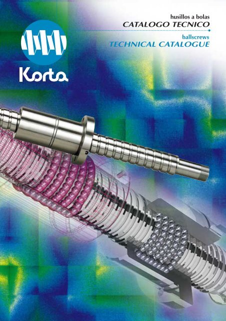
husillos a bolas<br />
CATALOGO TECNICO<br />
ballscrews<br />
TECHNICAL CATALOGUE
INTRODUCCION<br />
INTRODUCTION<br />
atesora una<br />
larga experiencia en el diseño,<br />
producción y comercialización de<br />
husillos a bolas. Nuestro constante<br />
esfuerzo en la búsqueda del más<br />
alto nivel de CALIDAD hace que<br />
podamos ofrecer al mercado un<br />
producto de calidad contrastada a<br />
nivel internacional.<br />
utiliza avanzados<br />
medios y tecnologías punteras<br />
de fabricación, sistemas<br />
informáticos y de CAD/CAM aplicados<br />
a la producción de husillos<br />
a bolas.<br />
con una clara<br />
política de aseguramiento de<br />
CALIDAD, dispone del Certificado<br />
de Registro de Empresa ER-<br />
071/2/96 de acuerdo con la norma<br />
UNE-EN ISO 9002.<br />
formado por<br />
un conjunto de PERSONAS altamente<br />
cualificadas, ofrece al mercado<br />
una vocación de SERVICIO<br />
pensada en el cliente, dando adecuadas<br />
soluciones a sus necesidades<br />
y respuesta rápida a todo<br />
tipo de aplicaciones.<br />
Empresa<br />
Registrada<br />
ER-071/2/96<br />
ISO 9002<br />
has been accumulating<br />
experience of the<br />
design, production and sales of<br />
ball screws for many years. Our<br />
ongoing effort to attain the highest<br />
level of QUALITY has enabled<br />
us to put an internationally<br />
approved quality product on the<br />
market.<br />
To make it,<br />
uses state-of-the-art production<br />
means, vanguard technologies,<br />
CAD/CAM and other computing<br />
systems specially adapted to the<br />
production of ball screws.<br />
also implements<br />
a plain Quality Assurance<br />
policy that has won us the<br />
Registered Firm Certificate No.<br />
ER-071/2/96 for compliance with<br />
the UNE-EN ISO 9002 standard.<br />
, staffed by a<br />
team of highly skilled PEOPLE,<br />
offers their customer-orientated<br />
SERVICE vocation to the market<br />
and provides adequate solutions<br />
to any demands and a quick<br />
response to all sorts of applications.
Contenido<br />
Index<br />
Página<br />
1. Servicio al cliente<br />
2. Calidad asegurada<br />
3. Características de los<br />
husillos a bolas<br />
4. Gama de fabricación<br />
5. Campos de aplicación<br />
6. Términos y definiciones<br />
7. Detalle de tuercas<br />
8. Condiciones de recepción<br />
9. Precarga y rigidez<br />
10. Cálculos de diseño<br />
- Cálculo a pandeo<br />
- Velocidad crítica<br />
- Capacidad de carga estática y<br />
dinámica<br />
- Duración de vida<br />
- Flexión del eje debido a su peso<br />
- Deformación térmica de eje<br />
- Torsión en el eje del husillo a<br />
bolas<br />
- Par de funcionamiento e inercia<br />
del sistema<br />
- Rendimiento y potencia<br />
- Ejemplo de cálculo<br />
11. Información general<br />
- Tipos de punta y ejemplos de<br />
montaje<br />
- Almacenaje y transporte<br />
- Temperatura de funcionamiento<br />
- Protección<br />
- Husillos a bolas huecos<br />
- Materiales<br />
- Lubricación<br />
- Montaje y desmontaje de la<br />
tuerca<br />
12. Precauciones a adoptar.<br />
Problemas y soluciones.<br />
13. Procedimiento de selección.<br />
14. Cuestionario.<br />
4<br />
6<br />
8<br />
10<br />
12<br />
13<br />
16<br />
21<br />
34<br />
46<br />
46<br />
48<br />
50<br />
52<br />
56<br />
57<br />
57<br />
58<br />
60<br />
61<br />
66<br />
66<br />
67<br />
67<br />
68<br />
68<br />
69<br />
69<br />
71<br />
72<br />
74<br />
75<br />
1. Service to the Customer<br />
2. Guaranteed Quality<br />
3. Characteristics of Ball Screws<br />
4. Production Range<br />
5. Fields of Use<br />
6. Terminology and Definitions<br />
7. Nut Design Details<br />
8. Acceptance Conditions<br />
9. Preload and Rigidity<br />
10. Design Calculations<br />
- Buckling Calculation<br />
- Critical Speed<br />
- Static and Dynamic Load Ratings<br />
- Life Expectancy<br />
- Deflection of Ball Screw Shaft under<br />
its own Weight<br />
- Thermal Deformation of Ball Screw Shaft<br />
- Torsion of the Ball Screw Shaft<br />
- Driving Torque and System Inertia<br />
- Efficiency and Power<br />
- Example of Ball Screw Calculation<br />
11. General Information<br />
- Types of Ends and Typical Mounting<br />
- Storage and Transport<br />
- Working Temperature<br />
- Protection<br />
- Hollow Shaft Ball Screws<br />
- Materials<br />
- Lubrication<br />
- Mounting and Dismantling of the Nut<br />
12. Preventive Measures. Problems and<br />
Solutions.<br />
13. Selection of Ball Screws<br />
14. Questionnaire<br />
Page<br />
4<br />
6<br />
8<br />
10<br />
12<br />
13<br />
16<br />
21<br />
34<br />
46<br />
46<br />
48<br />
50<br />
52<br />
56<br />
57<br />
57<br />
58<br />
60<br />
61<br />
66<br />
66<br />
67<br />
67<br />
68<br />
68<br />
69<br />
69<br />
71<br />
72<br />
74<br />
75<br />
3
1<br />
Servicio al cliente<br />
Service to the Customer<br />
Las principales ventajas ofrecidas por los<br />
husillos a bolas de precisión para el<br />
movimiento lineal, en sustitución de los clásicos<br />
husillos de rosca trapezoidal son un mayor<br />
rendimiento y eficacia, y una disminución de<br />
los costes de mantenimiento.<br />
Los clientes se benefician asímismo, de la<br />
posibilidad que les ofrece de escoger<br />
entre una de las gamas más amplias del mercado<br />
de husillos a bolas, lo que nos permite poder<br />
recomendar y suministrar el husillo a bolas más<br />
adecuado a cada tipo de aplicación.<br />
Nuestro objetivo primordial es el de prestar<br />
un servicio adecuado y de calidad al cliente.<br />
trata de mejorar continuamente con el<br />
fin de seguir siendo uno de los líderes mundiales<br />
en gama de producto, calidad, asesoramiento<br />
técnico, plazo de entrega y precios.<br />
A su vez poseemos un servicio de reparación<br />
de husillos a bolas para atender todo tipo<br />
de urgencias.<br />
Higher performance and efficiency combined<br />
with lower maintenance costs are the<br />
major advantages of high-accuracy ball<br />
screws for linear motion transmission over conventional<br />
trapezoidal thread screws.<br />
The customers also benefit from<br />
enabling them to choose from one of the widest<br />
ranges in the ball screw market. This allows us<br />
to recommend and supply the most suitable<br />
ball screw for each type of application.<br />
Our primary objective is to give the customer<br />
an adequate and quality service.<br />
seeks continuous improvements in order to<br />
remain one of the sector’s leaders in the world,<br />
in terms of product range, quality, <strong>technical</strong><br />
advices, delivery times and prices.<br />
We have also established a ball screw<br />
repair service to see about any case of an emergency.<br />
Gama de producto<br />
Product range<br />
ofrece una amplia gama de husillos<br />
a bolas de precisión. Incluye distintos diámetros<br />
y pasos (izquierda y derecha), tuercas<br />
dobles ó simples, materiales estandard o inoxidables,<br />
en ejecución rectificada ó laminada; lo<br />
que nos permite seleccionar el más adecuado<br />
para su aplicación.<br />
Asímismo ofrece un extensísimo<br />
catálogo de medidas de husillos a bolas de precisión<br />
en STOCK según norma de y de<br />
norma DIN69051/5 y DIN69051/2.<br />
offers for sale a wide range of precision<br />
ball screws in various sizes and leads<br />
(left-handed and right-handed threads) with single<br />
or double nuts, made from standard or<br />
stainless materials, either ground or rolled. So,<br />
we can always select one ad-hoc for your application.<br />
Likewise, has in STOCK a full reference<br />
<strong>catalogue</strong> of high-accuracy ball screws as<br />
per , DIN 69051/5 and DIN 69051/2 standards.<br />
4<br />
Asesoramiento técnico<br />
Technical advices<br />
Nuestro departamento de I+D ha elaborado<br />
un banco de datos que reúne todos los parámetros<br />
importantes a la hora de medir la eficacia<br />
y rendimiento de un husillo a bolas, en una<br />
gama extremadamente variada de aplicaciones.<br />
Esto nos permite asesorarle técnicamente con<br />
Our R&D department have created a database<br />
regrouping all the parameters essential to<br />
evaluate the efficiency and performance of ball<br />
screws for an extremely diversified field of<br />
uses. We are thus in a position to advise you<br />
<strong>technical</strong>ly and help you to satisfy your applica-
el fin de cumplir con los requisitos específicos<br />
de su aplicación (aunque sea difícil predecir el<br />
rendimiento de un husillo a bolas bajo condiciones<br />
de trabajo extremas, siempre podremos<br />
efectuar una simulación de vida del husillo a<br />
bolas e incluso ver su comportamiento en los<br />
bancos de pruebas).<br />
Este asesoramiento incluye la selección<br />
del tipo de husillo a bolas más conveniente en<br />
cada caso, según diámetro, paso, precarga,<br />
material, lubricación, etc. El sistema CAD nos<br />
permite simular, optimizar y actualizar los diseños,<br />
por lo que podemos ofrecerle una rápida y<br />
adecuada respuesta.<br />
tion requirements. (Although it is hard to predict<br />
the behaviour of a ball screw under<br />
extreme operating conditions, we can always<br />
prepare a simulation of the ball screw life and<br />
see how the ball screw performs on a testbench.)<br />
Such an aid provides the choice of the<br />
ideal ball screw type, diameter, lead, preloading,<br />
material, lubrication, etc., for each concrete<br />
application. A CAD system permits us to simulate,<br />
optimize and update our designs, which<br />
enables us to give you a quick and appropriate<br />
answer.<br />
Entrega en plazo<br />
In-Time Delivery<br />
está equipado con maquinaria versátil<br />
y de grán capacidad de producción, organizada<br />
por células para distintas familias de<br />
fabricación y software que optimiza la entrega<br />
de pedidos según plazos y las carga de trabajo<br />
de cada máquina. Ello permite atender plazos<br />
de entrega con una mayor urgencia, sin que<br />
ello afecte a la entrega de pedidos previamente<br />
programada.<br />
Asímismo, utilizar husillos a bolas de<br />
nuestra gama de STOCK, le permite a Ud., disponer<br />
de unos plazos de entrega más reducidos.<br />
is equipped with high-output versatile<br />
machinery arranged in cells according to<br />
the different product families and has items of<br />
software to optimize the workload of each<br />
machine and the delivery of orders according to<br />
the required lead times. As a result, more<br />
urgent supplies can be served without altering<br />
previously scheduled deliveries.<br />
Moreover, if you can use any type of ball screws<br />
we have in STOCK, the lead time will be much<br />
shorter.<br />
Precios competitivos<br />
Competitive prices<br />
Nuestra mejora continua en medios de<br />
producción posibilita una reducción en nuestros<br />
costes de fabricación, beneficiándose<br />
implícitamente de unos precios más ajustados<br />
y competitivos.<br />
Si un husillo a bolas de nuestra gama de<br />
STOCK se adapta a sus necesidades, sin duda,<br />
utilícelo. Su precio será siempre inferior al de<br />
un husillo a bolas según plano del cliente.<br />
seleccionará el husillo a bolas más<br />
económico que cumple con las especificaciones<br />
y requisitos de calidad que Ud. nos exija.<br />
Ongoing improvement of our production<br />
facilities makes it possible for us to reduce our<br />
manufacturing costs. For you, this means you<br />
will profit by really near-cost and competitive<br />
prices.<br />
If any ball screw in our STOCK range fits your<br />
requirements, do not hesitate to use it. Its price<br />
will always be lower than that of a customized<br />
ball screw.<br />
will select the most cost-effective ball<br />
screw complying with the specifications and<br />
quality standards you would impose on us.<br />
5
2<br />
Calidad asegurada<br />
Guaranteed quality<br />
La definición de calidad de se basa<br />
en cumplir y satisfacer las necesidades del<br />
cliente, desde el principio hasta el final de cada<br />
pedido, siendo objetivo prioritario llegar a cero<br />
defectos. Es responsabilidad de todos y cada<br />
una de las personas pertenecientes a nuestra<br />
organización, el asegurar la calidad de los productos<br />
que suministremos al cliente.<br />
está regularmente sometido a<br />
auditorías por parte de nuestros clientes y organismos<br />
externos de inspección cualificados.<br />
Asímismo, nosotros auditamos a nuestros proveedores<br />
y subcontratistas, según procedimientos<br />
operativos establecidos en el manual<br />
de calidad.<br />
For , the quality concept is based<br />
on the fulfilment of and compliance with the<br />
customer’s requirements from the initial to the<br />
final stages of each order. Zero defects is our<br />
priority target and it is the responsability of<br />
every people within our organization to guarantee<br />
the quality of the products supplies<br />
to the customer.<br />
is regularly audited by customers<br />
and authorized independent regulatory<br />
agencies. In our turn, we audit our suppliers<br />
and subcontractors as per the operating procedures<br />
defined in our Quality Manual.<br />
Fig. 1 Certificado de precision de paso<br />
Lead accuracy certificate<br />
6<br />
Fig. 2 Certificado de par de precarga<br />
Preloading torque certificate
Fig. 3 Certificado de rigidez<br />
Rigidity certificate<br />
Fig. 4 Certificado dimensional<br />
Dimensional certificate<br />
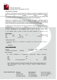
El sistema de aseguramiento de la calidad<br />
de<br />
dispone del Certificado de<br />
Registro de Empresa ER-071/2/96 de acuerdo<br />
con la norma UNE-EN ISO 9002.<br />
Certificados de control que<br />
suministrar:<br />
puede<br />
The Quality Assurance System in place at<br />
is attested by the Registered Firm<br />
Certificate ER-071/2/96 for compliance with the<br />
UNE-EN ISO 9002 standard.<br />
Control certificates<br />
may deliver cover:<br />
- Precisión de paso (figura 1).<br />
- Par de precarga (figura 2).<br />
- Rigidez (figura 3).<br />
- Tolerancias dimensionales y conformidad<br />
(figura 4).<br />
- Análisis químicos de materiales.<br />
- Tratamientos térmicos.<br />
- Detección de grietas por líquidos penetrantes.<br />
- Inspección por partículas magnéticas.<br />
- Lead accuracy (figure 1).<br />
- Preloading torque (figure 2).<br />
- Rigidity (figure 3).<br />
- Dimensional tolerances and conformity<br />
(figure 4).<br />
- Chemical analysis of the materials used.<br />
- Heat treatments.<br />
- Dye-penetrant crack detection.<br />
- Magnetic particle inspection.<br />
- Otros certificados de inspección. - Other inspections.<br />
7
3<br />
Características de los husilos a bolas<br />
Characteristics of ball screws<br />
Una de las principales novedades que<br />
encontramos en los husillos a bolas, es que el<br />
rozamiento por deslizamiento que se produce<br />
en los husillos convencionales es sustituido por<br />
un rozamiento de rodadura, de la misma manera<br />
que ocurre en los rodamientos, con las consiguientes<br />
ventajas que esto supone en favor<br />
de los accionamientos mandados por husillos a<br />
bolas.<br />
One of the main new features of<br />
ball screws is that the sliding friction produced<br />
by conventional screws has been replaced by a<br />
rolling friction, in the same way as occurs with<br />
ball bearings. The resultant advantages for ball<br />
screw-driven actuators are as listed below:<br />
Alta precisión<br />
High Accuracy<br />
cuida con rigor la calidad y precisión<br />
en la fabricación de los husillos a<br />
bolas, mediante sofisticados sistemas de<br />
medición (rayos láser, perfilómetros, proyectores<br />
de perfiles, rugosímetros, medidor<br />
de par continuo, etc.), haciendo algunas<br />
de las mediciones en un habitáculo<br />
donde existen grados de humedad y temperatura<br />
constantes para, de esta manera,<br />
no distorsionar el resultado de las mediciones<br />
por influencia de las condiciones<br />
ambientales.<br />
Rigorous quality and precision controls<br />
are carried out during the manufacturing<br />
process of ball screws, using<br />
sophisticated measuring systems (laser,<br />
profilometers, contour projectors, surface<br />
roughness testers, continuous torquemeters,<br />
etc.). Some of these measurements<br />
are performed in a controlled-atmosphere<br />
room where temperature and humidity<br />
are kept constant so that ambient conditions<br />
do not distort the test results.<br />
Alta rigidez y mínimo juego axial<br />
High Rigidity and Minimal Axial Play<br />
En un husillo convencional, si queremos<br />
minimizar de alguna manera el juego<br />
axial, llega un momento en que el par que<br />
tenemos que aplicar para conseguir el<br />
movimiento se acrecenta en exceso. Esto<br />
da lugar a que el husillo no trabaje con<br />
suavidad, e incluso pudiera haber la posibilidad<br />
de agarrotamiento. Con los husillos<br />
a bolas, consigue reducir a<br />
cero el juego axial mediante la aplicación<br />
de una precarga, consiguiendo así una<br />
gran suavidad de operación, a la vez que<br />
muy bajos pares de aplicación.<br />
When trying to minimize the axial play<br />
(backlash) of conventional screws by all<br />
means, it happens that the torque necessary<br />
to obtain the movement becomes<br />
excessive. As a consequence, the screw<br />
no longer operates smoothly and freezing<br />
may well occur. Through preloading the<br />
ball screw, have managed to eliminate<br />
axial play, thereby ensuring an<br />
extremely smooth operation and the use<br />
of very low drive torques.<br />
Suavidad de operación y alto rendimiento<br />
Smooth Operation and High Efficiency<br />
Debido al bajísimo coeficiente de rozamiento<br />
de rodadura que tienen los husillos<br />
a bolas en comparación con el rozamiento<br />
de los husillos convencionales, los prime-<br />
Due to the extremely low rolling friction<br />
coefficient of the ball screws in comparison<br />
with the sliding friction of conventional<br />
screws, the efficiency of the former is<br />
8
os tienen un rendimiento elevadísimo que<br />
puede llegar en algunos casos hasta cotas del<br />
97% y 98%.<br />
En la figura 5 se muestran dos gráficos en<br />
los que se puede apreciar la gran diferencia<br />
existente entre los rendimientos obtenidos con<br />
los husillos a bolas, en oposición con los rendimientos<br />
de los convencionales.<br />
η (%)<br />
1<br />
100<br />
90<br />
80<br />
70<br />
60<br />
50<br />
40<br />
30<br />
20<br />
10<br />
µ=0,003<br />
µ=0,005<br />
µ=0,01<br />
Husillos a bolas<br />
Ball screw<br />
µ=0,1<br />
µ=0,2<br />
Husillo convencional<br />
Conventional screw<br />
Rendimiento η (%)<br />
2<br />
Efficiency<br />
much higher, in some cases as much as 97%<br />
and 98%.<br />
Figure 5 shows two charts giving a good<br />
idea of the higher rates of efficiency achieved<br />
when using ball screws as opposed to the use<br />
of conventional screws.<br />
100<br />
90<br />
80<br />
70<br />
60<br />
50<br />
40<br />
30<br />
20<br />
10<br />
µ=0,003<br />
µ=0,005<br />
µ=0,01<br />
Husillos a bolas<br />
Ball screw<br />
Husillo convencional<br />
Conventional screw<br />
µ=0,1<br />
µ : Coeficiente de rozamiento<br />
µ : Friction coeficient<br />
0 1 2 3 4 5 6 7 8 9 10<br />
ϕ(º) Angulo de Hélice ( Grados )<br />
ϕ(º) Lead angles ϕ (Degrees) (º)<br />
Uso Uso normal: Conversión del movimiento<br />
de de rotación en en movimiento lineal.<br />
Normal use: use: transformation of of a rotary<br />
motion<br />
motion<br />
into<br />
into<br />
a linear<br />
linear<br />
motion.<br />
motion<br />
0 1 2 3 4 5 6 7 8 9 10<br />
Angulo de Hélice ( Grados )<br />
ϕ (º)<br />
Uso normal: Conversión del movimiento<br />
lineal Uso especial: en movimiento Conversión de rotación. del movimiento<br />
lineal Normal en use: movimiento transformation de rotación. of a rotary<br />
motion Special into use: a linear transformation motion of a linear<br />
µ: motion Coeficiente into a de rotary rozamiento. motion.<br />
µ: Friction coefficient<br />
Fig. 5. Rendimiento mecánico de los husillos a bolas KORTA<br />
Mechanical efficiency of KORTA ball screws<br />
Todas estas características descritas,<br />
hacen que los husillos a bolas tengan<br />
una gran duración, a la vez que proporcionan<br />
gran precisión de movimiento y posicionamiento.<br />
También, permiten velocidades de traslación<br />
muy superiores con respecto a los husillos convencionales<br />
de fileteado trapezoidal, menores<br />
vibraciones, deslizamientos, desgastes, calentamientos,<br />
y en definitiva menores potencias de<br />
arrastre. Por todo ello, asegura una elevada<br />
calidad en la fabricación del producto,<br />
para de esta manera, garantizar todas las ventajas<br />
descritas en favor de los husillos a bolas.<br />
El contacto con metal en un husillo convencional<br />
necesita una alta fuerza de puesta en<br />
marcha debido al rozamiento. Por el contrario,<br />
las bolas del husillo necesitan una pequeña<br />
fuerza para superar el rozamiento de rodadura.<br />
All those characteristics contribute to<br />
ensure the long service life of ball<br />
screws and their working with high positioning<br />
and motion accuracy. They also allow transfer<br />
speeds much higher than are obtained with<br />
conventional trapezoidal thread screws. Other<br />
interesting features are fewer vibrations and<br />
displacements, less wear and overheating and,<br />
finally, lower drive powers. To achieve this and<br />
to guarantee the described advantages of ball<br />
screws, cares for top quality throughout<br />
the product manufacturing process.<br />
Because of their metal-against-metal contact<br />
and subsequent sliding friction, conventional<br />
screws require a high initial driving force.<br />
By contrast, only a small force is needed by the<br />
balls of a ball screw to overcome the rolling<br />
friction.<br />
9
4<br />
Gama de fabricación<br />
Production Range<br />
Diámetro<br />
Diameter<br />
12<br />
16<br />
20<br />
25<br />
32<br />
40<br />
50<br />
63<br />
80<br />
100<br />
120<br />
Paso<br />
Lead<br />
4 5 6 8 10 12 16 20 25 32 40 50 64<br />
Pasos normalizados DIN<br />
DIN standard leads<br />
Tab. 1<br />
La tabla 1 muestra las medidas más usuales<br />
en la fabricación de husillos a bolas .<br />
Para la posibilidad de cualquier otra medida<br />
consultar con el departamento técnico de<br />
.<br />
The table 1 shows the most common sizes<br />
used in the manufacturing of ball<br />
screws. Please contact ’s Engineering<br />
Department about the possibility of dealing with<br />
other sizes.<br />
10<br />
Stock de husillos a bolas KORTA<br />
Stock of KORTA Ball screws<br />
Con el objetivo de minimizar el plazo de<br />
entrega de los husillos a bolas, ofrece<br />
una gama de medidas en stock. Esta gama en<br />
stock se divide en husillos según norma propia<br />
y según norma DIN 69051.<br />
En ambos casos los husillos se dividirán<br />
en husillos laminados y husillos rectificados.<br />
Los husillos laminados son muy apropiados<br />
para aplicaciones en las que las prestaciones<br />
que se exigen a este mecanismo, no son tan<br />
elevadas como en el caso de los husillos a bolas<br />
rectificados. En la fabricación de estos primeros<br />
ya no se incluye la operación de rectificado de<br />
rosca del husillo, (aunque sí el rectificado de<br />
rosca de la tuerca) y por consiguiente se obtiene<br />
un sustancial abaratamiento de su costo de<br />
fabricación y precio de venta.<br />
In order to minimize the delivery times,<br />
offers a range of ball screws in several<br />
sizes from permanent stocks. The said range<br />
comprises ball screws according to both<br />
’s own standard and the DIN 69051 standard.<br />
Each category is further divided into rolled<br />
ball screws and ground ball screws. Rolled ball<br />
screws are suitable for any application<br />
demanding a level of performance from this<br />
system, which need not be as high as that<br />
required from ground ball screws.<br />
Manufacturing of the former type excludes the<br />
grinding of the screw thread (but not of the nut<br />
thread); it ensues a substantial cutdown of this<br />
product manufacturing costs and selling price.
Gama de fabricación. Stock<br />
Production Range. Stock<br />
Norma KORTA<br />
KORTA standard<br />
• Husillos a bolas laminados o rectificados con<br />
tuerca simple RBS ó RS.<br />
• Rolled or ground ball screws with RBS or RS<br />
single nut.<br />
• Husillos a bolas rectificados con doble tuerca<br />
UDBS.<br />
• Ground ball screws with UDBS double nut.<br />
Diámetro<br />
Diameter<br />
16<br />
20<br />
25<br />
32<br />
40<br />
50<br />
63<br />
Tab. 2<br />
Diámetro<br />
Diameter<br />
16<br />
20<br />
25<br />
32<br />
40<br />
50<br />
63<br />
Tab. 3<br />
Paso<br />
Lead<br />
5 10 20 40<br />
Paso<br />
Lead<br />
5 10 20 40<br />
Norma DIN 69051<br />
DIN 69051 standard<br />
• Husillos a bolas laminados ó rectificados con<br />
tuerca simple KBS.<br />
• Rolled or ground ball screws with KBS single<br />
nut.<br />
• Husillos a bolas rectificados con tuerca<br />
doble EDBS.<br />
• Ground ball screws with EDBS double<br />
nut.<br />
DIN 69051/5<br />
DIN 69051/2<br />
Paso no normalizado / Non standard lead<br />
Diámetro<br />
Diameter<br />
16<br />
20<br />
25<br />
32<br />
40<br />
50<br />
63<br />
Tab. 4<br />
Paso<br />
Lead<br />
5 10 20 32 40<br />
11
5<br />
Campos de aplicación<br />
Fields of use<br />
Los husillos a bolas se utilizan exitosamente<br />
en las siguientes áreas:<br />
• Máquina-herramienta CNC.<br />
• Centros de mecanizado CNC<br />
• Tornos CNC<br />
• Fresadoras CNC<br />
• Rectificadoras CNC<br />
• Máquina-herramienta en general<br />
• Máquinas de empaquetamiento<br />
· Máquinas de impresión<br />
• Máquinas de procesamiento de plásticos<br />
• Mesas X-Y<br />
• Unidades elevadoras<br />
• Actuadores<br />
• Industria del metal<br />
• Industria del automóvil<br />
• Industria aeronaútica<br />
• Tecnología médica<br />
• Aparatos de rayos X<br />
• Camas de hospital<br />
• Industria alimentaria<br />
• Sector farmaceútico<br />
• Industria nuclear<br />
Ball screws are successfully used in the following<br />
areas:<br />
• CNC Machine-Tools<br />
• CNC Machining Centres<br />
• CNC Lathes<br />
• CNC Milling Machines<br />
• CNC Grinding Machines<br />
• Machine-Tools in general<br />
• Packing Machines<br />
• Printing Machines<br />
• Plastic-Processing Machinery<br />
• X-Y Tables<br />
• Lifting Equipment<br />
· Actuators<br />
• Metal Industry<br />
• Car Industry<br />
• Aircraft Industry<br />
• Medical Technology<br />
• X-ray machines<br />
• Hospital beds<br />
• Food Industry<br />
• Pharmaceutical Sector<br />
• Nuclear Industry<br />
Husillos a bolas<br />
Ball Screws<br />
12<br />
Fig. 6
6<br />
Términos y definiciones<br />
Terms and Definitions<br />
Términos y definiciones<br />
Términos y definiciones<br />
Tuerca<br />
Nut<br />
Bola<br />
Ball<br />
Dw<br />
α<br />
ϕ<br />
Dpw<br />
d0<br />
d1<br />
d2<br />
d3<br />
D4<br />
D<br />
D1<br />
Ph<br />
eje de husillo<br />
Screw shaft<br />
l 1<br />
Fig. 7<br />
d 0 = diámetro nominal<br />
d 1 = diámetro exterior del husillo<br />
d 2 = diámetro del núcleo del husillo a bolas<br />
d 3 = diámetro del asiento del cojinete<br />
D = diámetro exterior del cuerpo de tuerca<br />
D 4 = diámetro del núcleo del cuerpo de tuerca<br />
D 3 = diámetro interior del cuerpo de tuerca<br />
D pw = diámetro del círculo de centros de bola<br />
D w = diámetro nominal de la bola<br />
l 1 = longitud de rosca<br />
P h = paso<br />
α = ángulo de contacto entre bola y pista<br />
ϕ = ángulo de hélice<br />
Diámetro nominal d 0 : Es el valor utilizado<br />
para designar el husillo a bolas.<br />
Diámetro del círculo de centros de bola<br />
D pw : Es el diámetro del cilindro en el husillo a<br />
bolas que contiene los centros de las bolas<br />
cuando éstas tocan el husillo y la tuerca en los<br />
puntos de contactos teóricos ( α = 45°).<br />
Perfil de rosca: Es una ranura helicoidal<br />
en el husillo a bolas y en la tuerca para transmitir<br />
la carga de reacción entre ambas por<br />
medio de las bolas.<br />
d 0<br />
d 1<br />
d 2<br />
d 3<br />
D<br />
D 4<br />
D 3<br />
= nominal diameter<br />
= ball screw shaft outer diameter<br />
= ball screw shaft root diameter<br />
= journal diameter<br />
= ball nut body outer diameter<br />
= ball nut body root diameter<br />
= ball nut body internal diameter<br />
D pw = pitch circle diameter<br />
D w = nominal ball diameter<br />
l 1 = thread length<br />
P h = lead<br />
α = angle of contact between ball and track<br />
ϕ<br />
= lead angle<br />
Nominal diameter d 0 : is the size used to<br />
define a ball screw.<br />
Pitch circle diameter D pw : is the diameter<br />
of the cylinder containing the centres of<br />
the balls which are in contact with the screw<br />
shaft and the ball nut body at the theoretical<br />
contact points ( α = 45°).<br />
Ball track: refers to the helical groove cut<br />
in the screw shaft and in the nut for reaction<br />
load transmission between the ball nut body<br />
and the ball screw shaft through the balls.<br />
13
Términos y definiciones<br />
Terms and Definitions<br />
Perfil de rosca gótico (arco ojival): En<br />
este tipo de perfil la sección normal a través de<br />
la pista de bolas tiene la forma de un arco ojival<br />
gótico (ver figura 8).<br />
Gothic (ogival) groove: A ball track<br />
whose normal cross-section is in the form of a<br />
gothic or ogival arch (see figure 8).<br />
Tuerca<br />
Nut<br />
Bola<br />
Ball<br />
1/2s<br />
a<br />
1/2s<br />
r<br />
D /2 w<br />
r s<br />
r n<br />
1/2s<br />
r<br />
1/2s<br />
a<br />
ϕ<br />
Fig. 8<br />
eje del husillo<br />
screw shaft<br />
ha optado por el perfil ojival por<br />
varias razones:<br />
Permite que el ángulo de contacto entre<br />
husillo y bola esté comprendido entre 40º y 50º<br />
(lo ideal sería que fuese de 45º). Este hecho<br />
obliga a que la distribución de cargas sea<br />
mucho más racional, de manera que la rigidez<br />
del conjunto sea óptima. Por otra parte, el rozamiento,<br />
el desgaste, y el juego axial, se minimizan,<br />
permitiendo una mayor duración de vida<br />
del conjunto husillo-tuerca.<br />
has deemed it preferable to manufacture<br />
the gothic groove for several reasons:<br />
This type of ball track allows the contact<br />
angle between the screw and the ball to fall<br />
between 40º and 50º (the ideal angle being 45º).<br />
This means that the load distribution is much<br />
more rational, thereby providing optimum set<br />
rigidity. On the other hand, friction, wear and<br />
axial play are minimized, increasing the life<br />
expectancy of the screw-nut set.<br />
Ajuste f rn : Es la relación entre el radio de<br />
la pista de rodadura de la tuerca (r n ) y el diámetro<br />
nominal de las bolas (D w ).<br />
Conformity f rn : is the ratio of the nut ball<br />
track radius (r n ) to the nominal ball diameter<br />
(D w ):<br />
f rn = r n / D w<br />
(1)<br />
14
Ajuste f rs : Es la relación entre el radio de<br />
la pista de rodadura del eje del husillo (r s ) y el<br />
diámetro nominal de las bolas (D w ).<br />
Conformity f rs : is the ratio of the ball<br />
track radius of the ball screw shaft (r s ) to the<br />
nominal ball diameter (D w ):<br />
f rs = r s / D w<br />
(2)<br />
Angulo de contacto α: Es el ángulo<br />
entre una vertical hacia el eje del husillo a bolas<br />
y una línea a través de los puntos de contacto<br />
de una bola con la pista de rodadura de bolas<br />
del husillo y la pista de rodadura de la tuerca<br />
(ver figura 8).<br />
Contact angle α: is the angle between a<br />
perpendicular to the ball screw shaft axis and a<br />
line crossing the ball contact points at the<br />
screw shaft ball track and at the nut ball<br />
track(see figure 8).<br />
Angulo de hélice ϕ : Es el ángulo que<br />
forma el perfil de rosca con la sección transversal<br />
del eje del husillo a bolas (Ver figura 8).<br />
Lead angle ϕ: is the angle that the ball<br />
track forms with the cross-section of the ball<br />
screw shaft (see figure 8).<br />
tgϕ =<br />
P h<br />
(3)<br />
π D pw<br />
15<br />
Juego axial s a : Es el valor del desplazamiento<br />
axial entre la tuerca y el husillo a bolas<br />
(ver figura 8).<br />
Juego radial s r : Es el valor del desplazamiento<br />
radial entre la tuerca y el husillo a bolas<br />
(ver figura 8).<br />
Paso P h : Es el desplazamiento axial producido<br />
al girar la tuerca 2π radianes (1 vuelta)<br />
respecto al husillo a bolas (ver figura 8).<br />
Paso nominal P h0 : Es un valor de paso<br />
para la identificación general del tamaño de un<br />
husillo a bolas.<br />
Paso teórico P hs : Es una medida de paso<br />
ligeramente diferenciada del paso nominal y<br />
que se elige para compensar una alteración de<br />
la longitud causada por temperatura o por<br />
esfuerzo.<br />
Axial play (backlash) s a : is the value of<br />
the total axial displacement between the nut<br />
body and the screw shaft (see figure 8).<br />
Radial play s r : is the value of the radial<br />
displacement between the ball nut body and<br />
the ball screw shaft (see figure 8).<br />
Lead P h : refers to the axial displacement<br />
(travel) of the ball nut relative to the ball screw<br />
shaft for an angle of rotation of 2π rad (one revolution)<br />
(see figure 8).<br />
Nominal lead P h0 : is the lead value for<br />
general identification of the ball screw size.<br />
Specified lead P hs : is a lead size varying<br />
slightly from the nominal lead, which is selected<br />
to compensate for an expected elongation<br />
caused by an increase in temperature or a load.
7<br />
Detalle de tuercas<br />
Nut Design Details<br />
Las tuercas de los husillos a bolas se clasifican<br />
en función de estas características:<br />
• Tipo de recirculación.<br />
• Número de circuitos.<br />
• Forma de la tuerca.<br />
Nuts for ball screws are classified according<br />
to the following characteristics:<br />
• Type of recirculation system.<br />
• Number of circuits.<br />
• Nut shape.<br />
Tipos de recirculación<br />
Types of Recirculation<br />
introduce en su gama de fabricación<br />
el husillo con sistema de recirculación<br />
interna de bolas mediante “deflector”, debido<br />
entre otras razones, a que este sistema permite<br />
minimizar al máximo los diámetros exteriores<br />
de las tuercas. No obstante, también<br />
fabrica husillos a bolas de recirculación externa.<br />
We considered it useful that ’s<br />
range should include deflector-based internally<br />
recirculating ball screws, on the ground,<br />
among others, that such a system permits<br />
reducing the nut outside diameter to a minimum.<br />
however manufactures externally<br />
recirculating ball screws.<br />
1<br />
Husillos a bolas con recirculación interna<br />
Internally Recirculating Ball Screw<br />
En la figura 9 se muestra el sistema de<br />
recirculación de las bolas dentro de cada circuito.<br />
La pieza 1 corresponde a la tuerca, la 2 al<br />
deflector y la 3 a las bolas.<br />
Figure 9 shows how balls circulates<br />
through each circuit. Item 1 refers to the nut, 2<br />
to the deflector, 3 to the balls.<br />
2<br />
3<br />
1<br />
16<br />
Fig. 9 Tuerca con deflector de bolas<br />
Nut with ball deflector
Como se puede apreciar, la función del<br />
deflector consiste en “cerrar” un circuito de<br />
bolas mediante el paso de éstos de un hilo a<br />
otro de la tuerca, siempre y cuando sean éstos<br />
adyacentes. De esta manera, las dos o tres<br />
bolas que permanentemente se sumergen en el<br />
deflector no “trabajan”, es decir, no están<br />
sometidos a esfuerzos, con lo que pueden circular<br />
en el interior del deflector de manera flotante.<br />
As can be seen, the purpose of the deflector<br />
is “to close” the ball circuit and “to guide”<br />
the balls from one groove of the nut to the adjacent<br />
one. The two or three balls inside the<br />
deflector at any time do not “work”, that is to<br />
say, they are not submitted to any kind of stress<br />
and can thus circulate freely through the deflector.<br />
2<br />
Husillos a bolas con recirculación externa<br />
Externally Recirculating Ball screw<br />
Es otro de los sistemas de recirculación<br />
existentes dentro de la fabricación de<br />
los husillos a bolas (ver figura 10).<br />
These feature another ball circulating system<br />
available in the manufacture of ball screws<br />
(see figure 10).<br />
Fig. 10 Tuerca con recirculación externa<br />
External recirculation nut<br />
El cierre del circuito de las bolas se<br />
hace mediante un orificio pasante en la<br />
tuerca, siendo externo a las pistas de rodadura.<br />
Este diseño obliga a utilizar mayores<br />
diámetros de tuerca que en el caso del sistema<br />
de circulación con deflector.<br />
Closure of the ball circuit is by means of<br />
an opening passage in the nut body, which is<br />
external to the ball tracks.This design requires<br />
that the nut diameter be greater than would be<br />
necessary for a deflector-based ball recirculating<br />
system.<br />
17
Detalle de tuercas<br />
Nut Design Details<br />
Número de circuitos (i)<br />
Number of circuits (i)<br />
Las tuercas de los husillos a bolas suelen<br />
incluir distintos recorridos cerrados que realizan<br />
las bolas alrededor del eje del husillo. Cada<br />
una de las vueltas que realizan alrededor del eje<br />
del husillo se denomina circuito. La cantidad de<br />
circuitos en una tuerca suele oscilar entre los 2<br />
y los 6 circuitos.<br />
The nuts of ball screws normally present<br />
several closed paths in which the balls roll<br />
around the screw shaft. A circuit is defined as<br />
any single path for ball rotation around the ball<br />
screw shaft. The number of active circuits in a<br />
nut usually varies from 2 to 6.<br />
Fig. 11 Tres circuitos de una tuerca con recirculación externa<br />
Three circuits in an externally recirculating nut<br />
Fig. 12 Dos circuitos de una tuerca con recirculación interna<br />
Two circuits of an internally recirculating nut<br />
18
Tipos de tuerca<br />
Types of nuts<br />
Los tipos de tuerca de fabricación standard<br />
de son los siguientes, con la posibilidad<br />
de variaciones por exigencias o necesidades del<br />
cliente.<br />
manufactures the standard types<br />
of nuts listed below and is always willing to<br />
study customized designs.<br />
Tipo “S”: Tuerca simple<br />
Type “S”: Single nut<br />
RS<br />
Fig. 13<br />
Tipo “BS”: Tuerca simple con brida<br />
Type “BS”: Single nut with flange<br />
RBS<br />
KBS<br />
Tipo “WBS”: Tuerca simple con brida y resalte<br />
Type “WBS”: Single nut with end rim and flange<br />
Fig. 14<br />
Tipo “CBS”: Tuerca simple con brida centrada<br />
Type “CBS”: Single nut with centered flange<br />
Fig. 15<br />
BSL<br />
Fig. 16<br />
Tipo “S S”: Tuerca doble sin brida<br />
Type “S S”: Double nut without flange<br />
Fig. 17<br />
19
Detalle de tuercas<br />
Nut design details<br />
Tipo “BS S”: Tuerca doble con brida<br />
Type “BS S”: Double nut with single flange<br />
UDBS<br />
EDBS<br />
DBS<br />
Tipo “WBS S”: Tuerca doble con resalte y brida lateral<br />
Type “WBS S”: Double nut with end rim and flange<br />
Fig. 18<br />
Fig. 19<br />
Tipo “S BS”: Tuerca doble encastrada con brida<br />
Type “S BS”: Double encased nut with flange<br />
Fig. 20<br />
Tipo “S WBS”: Tuerca doble con resalte y brida centrada<br />
Type “S WBS”: Double nut with rim and centered flange<br />
Tipo “BS BS”: Tuerca doble con doble brida<br />
Type “BS BS”: Double nut with double flange<br />
Fig. 21<br />
20<br />
Fig. 22
8<br />
Condiciones de recepción<br />
Acceptance Conditions<br />
1<br />
Introducción<br />
Introduction<br />
En esta sección se especifican las condiciones<br />
técnicas de recepción y control de los<br />
husillos a bolas incluyendo las tolerancias válidas<br />
para los ensayos de recepción según la<br />
norma DIN 69051/3, relacionada con la norma<br />
ISO 3408/3.<br />
La recepción de husillos a bolas se realiza<br />
teniendo en cuenta las clases de tolerancia<br />
básicas según ISO 286/2:1988. Las desviaciones<br />
límites de cada ensayo se desglosan en las<br />
cinco clases de tolerancias básicas IT (ver tabla<br />
5).<br />
The object of this section is to specify the<br />
ball screw control and acceptance conditions,<br />
including admissible errors, for acceptance<br />
tests according to DIN 69051/3 which is related<br />
to the ISO 3408/3 standard.<br />
For the acceptance of ball screws, the<br />
basic tolerance grades defined in ISO<br />
286/2:1988 are borne in mind. The maximum<br />
permissible deviations for each test are classified<br />
in the five basic IT tolerance grades (see<br />
table 5).<br />
2<br />
Conceptos<br />
Concepts<br />
Los siguientes conceptos están dados<br />
según la norma DIN 69051/1, relacionado con la<br />
norma ISO 3408/1.<br />
l 0 = Recorrido nominal. Es el recorrido<br />
que se obtiene al girar la tuerca respecto al<br />
husillo, partiendo del paso nominal (ver página<br />
15) multiplicado por el número de revoluciones.<br />
l s = Recorrido teórico. Es el recorrido<br />
axial que se obtiene al girar la tuerca respecto<br />
al husillo, partiendo del paso teórico (ver página<br />
15) multiplicado por el número de revoluciones.<br />
l a = Recorrido real. Es el recorrido axial<br />
efectivo de una tuerca sobre un husillo o viceversa,<br />
después de un determinado número de<br />
vueltas.<br />
l u = Recorrido útil. Es el recorrido más la<br />
longitud de tuerca a bolas.<br />
l m = Recorrido real medio. Es el recorrido<br />
real promediado a lo largo del recorrido útil.<br />
l e = Sobre recorrido. Es el recorrido axial<br />
que se encuentra fuera del recorrido útil y que<br />
sirve de seguridad.<br />
c = Compensación del recorrido . Es la<br />
diferencia acordada entre el recorrido teórico y<br />
el nominal a lo largo del recorrido útil.<br />
The definitions of the following concepts<br />
are defined according to the DIN 69051/1 standard<br />
that refers to ISO 3408/1.<br />
l 0 = Nominal travel. This is the travel<br />
resulting from the rotation of the nut about the<br />
screw shaft and which is calculated by multiplying<br />
the nominal lead (see page 15) by the<br />
number of revolutions.<br />
l s = Specified travel. This is the axial<br />
displacement resulting from the rotation of the<br />
nut about the screw shaft, which is calculated<br />
by multiplying the specified lead (see page 15)<br />
by the number of revolutions.<br />
l a = Actual travel. This is the actual displacement<br />
of the ball nut relative to the ball<br />
screw shaft, or vice versa, for a given number<br />
of revolutions.<br />
l u = Useful travel. It is equal to the<br />
length of stroke plus the ball nut body length.<br />
l m = Actual mean travel. This is the<br />
averaged actual travel along the useful travel.<br />
l e = Excess travel. This is the axial displacement<br />
beyond the useful travel, which is<br />
provided for safety purposes.<br />
c = Travel compensation, the agreed<br />
difference between the specified travel and the<br />
nominal travel within the useful travel.<br />
21
Condiciones de recepción<br />
Acceptance Conditions<br />
e p = Tolerancia límite. Limita el campo<br />
de tolerancias para el recorrido real medio.<br />
e 0a = Desviación media del recorrido<br />
real que se obtiene de la diferencia entre el<br />
recorrido real medio (l m ) y el recorrido nominal<br />
(l 0 ) a lo largo del recorrido útil (l u ).<br />
e sa = Desviación media del recorrido<br />
real que se obtiene de la diferencia entre el<br />
recorrido real medio (l m ) y el recorrido teórico<br />
(l s ) a lo largo del recorrido útil (l u ).<br />
v= Oscilación del recorrido. La oscilación<br />
del recorrido v es el ancho de banda de las<br />
desviaciones del recorrido, siempre paralelamente<br />
al recorrido real medio respectivo. Están<br />
acordados los siguientes recorridos axiales:<br />
- 2π rad, con las correspondientes oscilaciones<br />
del recorrido υ 2π.<br />
- 300 mm, con las correspondientes oscilaciones<br />
de recorrido υ 300.<br />
- Recorrido útil, con las correspondientes oscilaciones<br />
de recorrido v u .<br />
e p = Tolerance on specified travel.<br />
This limits the scope of errors for the actual<br />
mean travel.<br />
e 0a = Actual mean travel deviation,<br />
which derives from the difference between the<br />
actual mean travel (l m ) and the nominal travel<br />
(l 0 ) within the useful travel (l u ).<br />
e sa = Actual mean travel deviation,<br />
which derives from the difference between the<br />
actual mean travel (l m ) and the specified travel<br />
(l s ) within the useful travel (l u ).<br />
v= Travel Variation. The corresponding<br />
band width parallel to the actual mean travel.<br />
The following travels have been defined:<br />
- 2π rad, with the corresponding band width υ 2π.<br />
- 300 mm, with the corresponding band width<br />
υ 300.<br />
- useful travel, with the corresponding band<br />
width v u.<br />
2.1<br />
Determinación gráfica del recorrido real medio<br />
Graphic Evaluation of the Actual Mean travel<br />
La determinación de la desviación media<br />
del recorrido real del diagrama de desviaciones<br />
de recorrido se realiza como sigue (ver figs. 23<br />
y 24):<br />
a) Tirar una o varias líneas rectas (l 1 ,l 2 …)<br />
que toquen como mínimo dos puntas superiores<br />
de la curva de desviación del recorrido real<br />
repitiendo esta operación para las puntas inferiores<br />
(l 3 …).<br />
b) Determinar la máxima distancia (e 1 , e 2 ,<br />
e 3 ) entre las rectas l 1 , l 2 y l 3 y la curva de desviación<br />
del recorrido real y elegir la distancia<br />
más corta. En las figuras 23 y 24 la distancia e 2 .<br />
c) A tavés de este punto de la mínima distancia<br />
y paralelamente a la recta correspondiente<br />
se tira otra recta (l’ 2 paralela a l 2 ).<br />
The evaluation of the actual mean travel<br />
deviation from the travel deviation diagram is<br />
carried out as follows (see fig. 23 and 24):<br />
a) Draw one or several tangents (l 1 ,<br />
l 2 ,...) to the actual travel deviation curve at two<br />
or more upper peaks. Repeat this procedure for<br />
the lower peaks (l 3 ,...).<br />
b) Determine the maximum span (e 1 ,<br />
e 2 , e 3 ) between straight lines l 1 , l 2 and l 3 and<br />
the actual travel deviation curve and select the<br />
smallest distance (on figures 23 and 24, distance<br />
e 2 ).<br />
c) Draw a straight line through the<br />
point of the minimum distance, that is parallel<br />
to the corresponding peak line (l’ 2 parallel to l2 ).<br />
22<br />
d) Se obtiene así la desviación real media<br />
e sa ó e 0a como línea central entre estas dos rectas<br />
paralelas (l’ 2 , l 2 ) y el ancho de la banda de la<br />
oscilación del recorrido v ua sobre el recorrido<br />
útil l u como la distancia entre las paralelas (e 2 ).<br />
d) Then, the actual mean travel deviation<br />
e sa or e 0a is the centreline between these<br />
parallel lines (l’ 2 and l 2 ) and the travel variation<br />
band width v ua within the useful travel l u is the<br />
distance between the parallel lines (e 2 ).
e1<br />
0´<br />
0<br />
Recorrido nominal<br />
Nominal travel<br />
ep<br />
Divergencia de recorrido<br />
Travel deviation<br />
e3<br />
c<br />
e2 =vua<br />
l 3<br />
l 1<br />
l 2<br />
eoa<br />
ep<br />
l´2<br />
l<br />
l e<br />
l u<br />
l e<br />
Fig. 23. Determinación gráfica del error medio del recorrido real (e 0a ), referido al recorrido nominal con compensación del recorrido (c).<br />
Graphic determination of the actual mean travel deviation (e 0a ) related to the compensated nominal travel (c).<br />
e1<br />
ep<br />
0´<br />
0<br />
Divergencia de recorrido<br />
Travel deviation<br />
e3<br />
l 3<br />
e2 =vua<br />
l 1<br />
l 2<br />
Recorrido teórico<br />
Specified travel<br />
esa<br />
ep<br />
l´2<br />
l<br />
l e<br />
l u<br />
l e<br />
Fig. 24. Determinación gráfica del error medio del recorrido real (e sa ), referido al recorrido teórico (c=0).<br />
Graphic determination of the actual mean travel deviation (e sa ) related to the specified travel (c=0).<br />
23
Condiciones de recepción<br />
Acceptance Conditions<br />
3<br />
Ensayos y tolerancias<br />
Tests and Tolerances<br />
A continuación se muestran todos los<br />
ensayos de recepción recomendadas por la<br />
norma DIN 96051.<br />
Se debe tener en cuenta que los ensayos a<br />
realizar para un husillo de posicionamiento y<br />
otro de transporte son distintos (ver figura 25 ),<br />
concretamente en los ensayos de comprobación<br />
de las desviaciones y oscilaciones del recorrido<br />
(apartado 3.1.1).<br />
All acceptance tests recommended under<br />
the DIN 96051 standard are referred to below.<br />
It should be remembered that the tests to<br />
be performed on positioning ball screws differ<br />
from those to be made on transport ball screws<br />
(see figure 25). This specially applies to checking<br />
of travel deviations and variations (section<br />
3.1.1.).<br />
Clase de tolerancia IT1 / Standard tolerance grade IT1<br />
Clase de tolerancia IT3 / Standard tolerance grade IT3<br />
Clase de tolerancia IT5 / Standard tolerance grade IT5<br />
Clase de tolerancia IT7 / Standard tolerance grade IT7<br />
Clase de tolerancia IT10 / Standard tolerance grade IT10<br />
Exigencias crecientes de precisión<br />
y funcionamiento<br />
Increasing requirements on accuracy<br />
and function<br />
Tab.5<br />
Husillos a bolas de posicionamiento<br />
P<br />
Position Ball Screws<br />
Sistema de medición indirecta<br />
Indirect Measuring System<br />
T<br />
Husillos a bolas de transporte<br />
Transport Ball Screws<br />
Sistemas de medición directa<br />
Direct Measuring System<br />
Μ<br />
Encoder<br />
Encoder<br />
Μ<br />
Escala lineal<br />
Linear scalel<br />
Motor paso a paso<br />
Step-by-step motor<br />
Final de carrera<br />
Limit switch<br />
Μ<br />
Fig. 25<br />
Μ<br />
24<br />
• Ensayos geométricos.<br />
• Comprobación de las desviaciones y<br />
oscilaciones de recorrido (se realizan para<br />
todos los husillos a bolas de precisión IT1 y IT3).<br />
• Control para tolerancias de rodadura y<br />
posición (se realizan para todos los<br />
husillos a bolas).<br />
• Ensayos de funcionamiento (se realizan bajo<br />
petición del cliente).<br />
•Geometrical tests.<br />
• Travel deviation and variation tests<br />
(applicable to all IT1 and IT3 precision<br />
ball screws).<br />
• Checking of run-out and location<br />
tolerances (applicable to all ball<br />
screws).<br />
• Functional tests (will be carried out on<br />
the customer’s request).
3.1<br />
Ensayos geométricos<br />
Geometrical Tests<br />
Las diferencias de medida límite (e p ) del<br />
recorrido teórico sobre el recorrido útil (véase<br />
ensayo 1.1 y 1.2) y los valores para oscilación<br />
del recorrido υ 300 sobre un recorrido axial de<br />
300 mm (ensayo 3) se han tomado de ISO 286/2:<br />
1988.<br />
Las tolerancias de la oscilación del recorrido<br />
v up sobre el recorrido útil (l u ) se han calculado<br />
de acuerdo con las siguientes ecuaciones<br />
obtenidas de forma experimental:<br />
Tolerances on specified travel (e p ) for a<br />
given useful travel (see tests 1.1 and 1.2) and<br />
the travel variation values υ 300 for a 300mm<br />
axial travel (test 3) are directly traceable to ISO<br />
286/2:1988.<br />
Tolerances on travel variation v up within<br />
the useful travel (l u ) have been calculated by<br />
applying the following equations obtained<br />
experimentally:<br />
IT1: v up = 0,0046 * l u + 4,6(µm)<br />
IT3: v up = 0,0092 * l u + 9,2(µm)<br />
IT5: v up = 0,0184 * l u + 18,4(µm)<br />
Utilizando como el valor de l u su media geométrica.<br />
Where l u is the geometric mean of useful travel.<br />
3.1.1. Comprobación de las desviaciones y oscilaciones de recorrido<br />
3.1.1. Travel Deviation and Variation Tests<br />
En la tabla 6 se muestran la totalidad de<br />
los ensayos que se realizan, distinguiendo entre<br />
husillos a bolas de posicionamiento y de transporte.<br />
Desviación del recorrido<br />
Travel deviation<br />
The table 6 shows all the tests that are<br />
performed on positioning ball screws and<br />
transport ball screws respectively.<br />
P<br />
T<br />
c: Compensación del recorrido sobre el recorrido útil l u<br />
Travel compensation for useful travel l u<br />
e p : Límite de la desviación media del recorrido real sobre el recorrido útil l u<br />
Maximum permissible measurement error for the mean actual travel deviation<br />
V up : Límite de la oscilación del recorrido v u a lo largo del recorrido útil l u .<br />
Permissible travel variation v u within the useful travel l u<br />
υ 300p : Límite de la oscilación del recorrido υ 300 sobre un recorrido axial de 300 mm<br />
Permissible travel variation υ 300 within a useful travel of 300 mm<br />
υ 2πp : Límite de la oscilación del recorrido υ 2π dentro de 2π radianes (1 vuelta)<br />
Permissible travel variation υ 2π within 2π rad (1 revolution)<br />
Tab. 6<br />
Fijado por el usuario<br />
Specified by user<br />
Ensayo 1.1<br />
Test 1.1.<br />
Ensayo 2<br />
Test 2<br />
Ensayo 3<br />
Test 3<br />
Ensayo 4<br />
Test 4<br />
c = 0<br />
Ensayo 1.2<br />
Test 1.2<br />
Ninguno<br />
None<br />
Ensayo 3<br />
Test 3<br />
Ninguno<br />
None<br />
El número mínimo de mediciones dentro<br />
de 300 mm que se deben realizar en cada ensayo<br />
y la longitud de la sobre recorrido máximo<br />
(l e ) se tomarán de la tabla 7.<br />
The minimum number of measurements<br />
over any travel of 300mm, per test, and the<br />
maximum excess travel (l e ) will be according to<br />
the table 7.<br />
Tolerancia / Tolerance<br />
Paso (P h )<br />
Lead (P h )<br />
1<br />
3<br />
5<br />
7<br />
10<br />
Sobre recorrido Máximo (l e )<br />
Excess Travel Maximun (l e )<br />
5<br />
10<br />
20<br />
40<br />
15<br />
10<br />
5<br />
-<br />
10<br />
5<br />
5<br />
2<br />
6<br />
3<br />
3<br />
1<br />
3<br />
1<br />
1<br />
1<br />
1<br />
1<br />
1<br />
1<br />
20<br />
40<br />
60<br />
100<br />
Tab.7<br />
25
Condiciones de recepción<br />
Acceptance Conditions<br />
l 1<br />
l e<br />
+<br />
l u<br />
l e<br />
l 0<br />
-<br />
300<br />
l 0<br />
υ2πp<br />
e p e p<br />
υ 300p<br />
2π rad<br />
v up v up<br />
c<br />
• Ensayo 1.1<br />
• Test 1.1<br />
Fig. 26 Desviaciones y oscilaciones de recorrido admisibles, referidas al recorrido nominal.<br />
Permissible travel deviation and travel variation in relation to the nominal travel.<br />
Límites de la desviación media del recorrido<br />
real sobre el recorrido útil referido al recorrido<br />
nominal (e 0a ) o al recorrido teórico(e sa ).<br />
Maximum actual mean travel deviations<br />
over the useful travel, related to the nominal<br />
travel (e 0a ) or the specified travel (e sa ).<br />
> < 1 3 5 7 10<br />
315<br />
400<br />
500<br />
630<br />
800<br />
1000<br />
1250<br />
1600<br />
2000<br />
2500<br />
3150<br />
4000<br />
5000<br />
6300<br />
7<br />
8<br />
9<br />
10<br />
11<br />
13<br />
15<br />
18<br />
22<br />
26<br />
32<br />
39<br />
48<br />
12<br />
13<br />
15<br />
16<br />
18<br />
21<br />
24<br />
29<br />
35<br />
41<br />
50<br />
62<br />
76<br />
96<br />
23<br />
25<br />
27<br />
30<br />
35<br />
40<br />
46<br />
54<br />
65<br />
77<br />
93<br />
115<br />
140<br />
170<br />
52<br />
57<br />
63<br />
70<br />
80<br />
90<br />
105<br />
125<br />
150<br />
175<br />
210<br />
260<br />
320<br />
390<br />
315<br />
400<br />
500<br />
630<br />
800<br />
1000<br />
1250<br />
1600<br />
2000<br />
2500<br />
3150<br />
4000<br />
5000<br />
Tab.8<br />
l u<br />
6<br />
e p (µm)<br />
Tolerancia / Tolerance<br />
210<br />
230<br />
250<br />
280<br />
320<br />
360<br />
420<br />
500<br />
600<br />
700<br />
860<br />
1050<br />
1300<br />
1550<br />
• Ensayo 3<br />
• Test 3<br />
26<br />
Límites de la oscilación del<br />
recorrido υ 300 sobre un recorrido<br />
axial de 300 mm.<br />
Permissible travel variation<br />
υ 300 within a 300mm axial travel.<br />
DIN, ISO<br />
BSI<br />
JIS<br />
υ 300p<br />
0<br />
3,5<br />
1<br />
5<br />
Tab.9<br />
1<br />
1<br />
6<br />
3<br />
8<br />
υ 300p (µm)<br />
Tolerancia / Tolerance<br />
3<br />
3<br />
12<br />
5<br />
18<br />
5<br />
5<br />
23<br />
7<br />
50<br />
7<br />
7<br />
52<br />
10<br />
10<br />
10<br />
210
• Ensayo 1.2<br />
• Test 1.2<br />
Límites de la desviación media del recorrido<br />
real sobre el recorrido útil (e 0a ).<br />
Maximum actual mean travel deviation<br />
within the useful travel (e 0a ).<br />
Divergencia recorrido<br />
Travel deviation<br />
-<br />
+l u<br />
-e oa<br />
-e p +e p<br />
Fig. 27<br />
recorrido nominal<br />
nominal travel<br />
e p = 2 l u<br />
υ<br />
300 v 300p<br />
p<br />
• Ensayo 2<br />
• Test 2<br />
Límites de la oscilación del recorrido v u a<br />
lo largo del recorrido útil (l u ).<br />
Limit travel variation v u within useful<br />
travel (l u ).<br />
315<br />
400<br />
500<br />
630<br />
800<br />
1000<br />
1250<br />
1600<br />
2000<br />
2500<br />
3150<br />
4000<br />
5000<br />
l u<br />
6<br />
315<br />
400<br />
500<br />
630<br />
800<br />
1000<br />
1250<br />
1600<br />
2000<br />
2500<br />
3150<br />
4000<br />
5000<br />
6300<br />
Tolerancia / Tolerance<br />
> < 1 3 5<br />
6<br />
7<br />
7<br />
8<br />
9<br />
10<br />
11<br />
13<br />
15<br />
17<br />
21<br />
-<br />
-<br />
v up (µm)<br />
12<br />
12<br />
13<br />
14<br />
16<br />
17<br />
19<br />
22<br />
25<br />
29<br />
34<br />
41<br />
49<br />
-<br />
23<br />
25<br />
26<br />
29<br />
31<br />
35<br />
39<br />
44<br />
51<br />
59<br />
69<br />
82<br />
99<br />
119<br />
Tab.10<br />
• Ensayo 4<br />
• Test 4<br />
Límites de la oscilación del recorrido υ 2π<br />
dentro de 2π radianes (1 vuelta).<br />
Limit travel variation υ 2π within 2π rad<br />
(1 revolution).<br />
1<br />
4<br />
Tab.11<br />
Tolerancia / Tolerance<br />
3<br />
6<br />
υ 2πp (µm)<br />
5<br />
8<br />
7<br />
10<br />
10<br />
10<br />
27
Condiciones de recepción<br />
Acceptance Conditions<br />
3.1.2. Control de recepción para tolerancias de rodadura y posición<br />
3.1.2. Acceptance Tests for Run-out and Location Tolerances<br />
En todos los ensayos se utilizarán indicadores<br />
finos según DIN 879 sección 1 y prismas<br />
de comprobación según DIN 2274, pareados. El<br />
husillo se alojará en los prismas de comprobación<br />
en los puntos A y A’.<br />
All the tests shall be carried out using precision<br />
gauges as per DIN 879 Section 1 and<br />
paired V-blocks in accordance to DIN 2274. The<br />
ball screw shall be placed on the V-blocks at<br />
points A and A’.<br />
• Ensayo 5<br />
• Test 5<br />
Defecto de redondez t 5 del diámetro exterior<br />
del husillo a bolas sobre la longitud l 5 para<br />
determinar la rectitud referida a AA’.<br />
l5 l5 l5<br />
d o<br />
Radial run-out t 5 of ball screw shaft outer<br />
diameter for determining straightness related<br />
to AA’ per length l 5 .<br />
2 d o<br />
A<br />
l1<br />
A´<br />
2 d o<br />
Instrucciones del ensayo<br />
t5p<br />
A<br />
l5<br />
l5<br />
t5max<br />
A´<br />
Colocar el indicador perpendicularmente al eje a una<br />
distancia l 5 del punto de apoyo A. Girar lentamente el husillo<br />
y leer durante una vuelta el defecto de redondez t 5a como<br />
la diferencia entre la indicación máxima y mínima. Repetir<br />
la medición a las distancias l 5 indicadas. Previo acuerdo<br />
apoyar husillo entre puntos. Cuando l 1 < 2l 5 realizar mediciones<br />
en l 1 /2. Tener cuidado que los resultados de medición<br />
no se vean afectados por otros errores inherentes a la<br />
tuerca (girar siempre en sentido contrario a la posición de<br />
medición).<br />
Test Instructions<br />
Tab.12<br />
d 0<br />
Fig. 28<br />
> <<br />
6<br />
12<br />
25<br />
50<br />
100<br />
12<br />
25<br />
50<br />
100<br />
200<br />
l 5<br />
80<br />
160<br />
315<br />
630<br />
1250<br />
t 50 (µm)<br />
tolerancia / tolerance<br />
1 3 5 7 10<br />
20 25 32 40 80<br />
20 25 32 40 80<br />
20 25 32 40 80<br />
20 25 32 40 80<br />
20 25 32 40 80<br />
Place the gauge perpendicular to the ball screw shaft<br />
axis at a distance l 5 from supporting point A. Rotate the ball<br />
screw slowly and determine the run-out t 5a for one revolution<br />
as the difference between the highest and lowest readings.<br />
Repeat the measurement at the specified distances l 5 .<br />
Subject to prior agreement, make the test with the ball<br />
screw shaft supported between centres. If l 1 < 2l 5 , take measurement<br />
for tolerance grades at l 1 /2. Take care that the test<br />
results are not affected by errors inherent in the nut (rotation<br />
to take place in the direction opposite to the measuring<br />
position).<br />
40<br />
60<br />
80<br />
Tab.13<br />
l 1 /d 0<br />
> <<br />
40<br />
60<br />
80<br />
100<br />
t 5máx. (µm) para/for l 1 >4l 5<br />
tolerancia / tolerance<br />
1 3 5 7 10<br />
40<br />
60<br />
100<br />
160<br />
50<br />
75<br />
125<br />
200<br />
64<br />
96<br />
160<br />
256<br />
80<br />
120<br />
200<br />
320<br />
160<br />
240<br />
400<br />
640<br />
28
• Ensayo 6<br />
• Test 6<br />
Defecto de redondez t 6 del asiento de<br />
rodamiento referido a AA’ para l 6 < l.<br />
Radial run-out t 6 of bearing diameter related<br />
to AA’ for l 6 < l.<br />
2 d 0<br />
l 6<br />
A A´<br />
d 0<br />
Instrucciones del ensayo<br />
Fig. 29.<br />
Colocar el indicador en el pivote del asiento a la distancia<br />
l 6 verticalmente a la superficie lateral. Girar lentamente<br />
el husillo y leer el defecto de redondez t 6a como la<br />
diferencia entre la indicación máxima y mínima durante<br />
una vuelta entera.<br />
Test Instructions<br />
Put the gauge on the bearing pin, at a distance l6, perpendicular<br />
to the cylindrical surface. Rotate the ball screw<br />
slowly and determine the run-out t 6a as the difference<br />
between the highest and lowest readings during one full<br />
revolution.<br />
6<br />
20<br />
50<br />
125<br />
Tab.14<br />
Para l 6 > l, se utiliza: t 6a < t 6p · I 6 /l<br />
For l 6 > l, use: t 6a < t 6p · l 6 /l<br />
d 0<br />
> <<br />
20<br />
50<br />
125<br />
200<br />
l<br />
80<br />
125<br />
200<br />
315<br />
1<br />
10<br />
12<br />
10<br />
-<br />
t 6p (µm) para/for l 6 < l<br />
tolerancia / tolerance<br />
3<br />
12<br />
16<br />
20<br />
25<br />
5<br />
20<br />
25<br />
32<br />
40<br />
7<br />
40<br />
50<br />
63<br />
80<br />
10<br />
63<br />
80<br />
100<br />
125<br />
• Ensayo 7<br />
• Test 7<br />
Defecto de coaxialidad t 7 de la espiga final<br />
del husillo a bolas referido al asiento de rodamiento<br />
(medición de diferencias) para l 7 l, se utiliza: t 7a < t 7p · l 7 /l<br />
For l 7 > l, use: t 7a < t 7p · l 7 /l<br />
d 0<br />
> <<br />
6 20<br />
20 50<br />
50 125<br />
125 200<br />
Tab.15<br />
l<br />
80<br />
125<br />
200<br />
315<br />
1<br />
5<br />
6<br />
8<br />
-<br />
d 0<br />
t 7p (µm) para/for l 7 < l<br />
tolerancia / tolerance<br />
3<br />
6<br />
8<br />
10<br />
12<br />
5<br />
8<br />
10<br />
12<br />
16<br />
7<br />
12<br />
16<br />
20<br />
25<br />
10<br />
16<br />
20<br />
25<br />
32<br />
29
Condiciones de recepción<br />
Acceptance Conditions<br />
• Ensayo 8<br />
• Test 8<br />
Diferencia de refrentado t 8 del apoyo del<br />
pivote del asiento del husillo a bolas referido<br />
AA’.<br />
Axial run-out t 8 of ball screw shaft bearing<br />
faces related to AA’.<br />
Asiento<br />
Bearing Seat<br />
d<br />
d<br />
A A´<br />
F<br />
d 0<br />
Instrucciones del ensayo<br />
2 d 0<br />
Asegurar el husillo en sentido axial contra desplazamieto<br />
(p. ej. mediante bola entre punto de centrado y superficie<br />
de contacto). Colocar el indicador perpendicular a la<br />
superficie envolvente del pivote y a la superficie plana del<br />
hombro del pivote del asiento. Girar lentamente el husillo y<br />
leer el valor de t 8a como la diferencia entre la indicación<br />
máxima y mínima durante una vuelta entera. En algún caso<br />
se puede considerar la ∆.<br />
Fig. 31<br />
t 8a<br />
+ ∆ ≤ t 8p<br />
∆: Partiendo de la divergencia respecto a la<br />
línea recta<br />
∆: Deviation from straightness<br />
Test Instructions<br />
Secure the ball screw shaft in the axial direction<br />
against movement (e.g. by placing a ball between the centres<br />
of the ball screw shaft and the mounting surface). Place the<br />
gauges perpendicular to the cylindrical surface of the journal<br />
and to the end face of the bearing pin. Rotate the ball<br />
screw slowly and determine the value of t 8a as the difference<br />
between the highest and lowest readings during one<br />
full revolution. In some cases, ∆ may be considered.<br />
><br />
6<br />
63<br />
125<br />
Tab.16<br />
d 0<br />
t 8p (µm)<br />
tolerancia / tolerance<br />
<<br />
63<br />
125<br />
200<br />
1<br />
3<br />
4<br />
-<br />
3<br />
4<br />
5<br />
6<br />
5<br />
5<br />
6<br />
8<br />
7<br />
6<br />
8<br />
10<br />
10<br />
10<br />
12<br />
16<br />
• Ensayo 9<br />
• Test 9<br />
Diferencia de refrentado t 9 de la superficie<br />
de contacto de la tuerca a bolas referido AA’<br />
(sólo para tuercas con precarga).<br />
Axial run-out t 9 of ball nut location face<br />
related to AA’ (for preloaded ball nuts only).<br />
A<br />
D 2<br />
F<br />
A´<br />
d 0<br />
Instrucciones del ensayo<br />
2 d 0<br />
2 d 0<br />
30<br />
Asegurar el husillo en sentido axial contra desplazamieto<br />
(p. ej. mediante bola entre punto de centrado y superficie<br />
de contacto). Asegurar la tuerca contra el giro con respecto<br />
al husillo. Colocar el indicador perpendicular a la<br />
superficie de contacto de la brida de la tuerca en su diámetro<br />
máximo posible. Girar lentamente el husillo con la tuerca<br />
y leer el valor de t 9a como la diferencia entre la indicación<br />
máxima y mínima durante una vuelta entera.<br />
Test Instructions<br />
Secure the ball screw shaft in the axial direction<br />
against movement (e.g. by placing a ball between the centres<br />
of the ball screw shaft and the mounting surface). Secure<br />
the ball nut against rotation on the ball screw shaft. Place<br />
the gauge perpendicular to the nut flange face at its outermost<br />
diameter. Rotate the ball screw shaft slowly with the<br />
nut and determine the value t 9a as the difference between<br />
the highest and lowest readings during one full revolution.<br />
Fig.32<br />
16<br />
32<br />
63<br />
125<br />
250<br />
Tab.17<br />
D 2<br />
> <<br />
32<br />
63<br />
125<br />
250<br />
500<br />
1<br />
10<br />
12<br />
16<br />
20<br />
-<br />
t 9p (µm)<br />
tolerancia / tolerance<br />
3<br />
12<br />
16<br />
20<br />
25<br />
32<br />
5<br />
16<br />
20<br />
25<br />
32<br />
40<br />
7<br />
20<br />
25<br />
32<br />
40<br />
50<br />
10<br />
-<br />
-<br />
-<br />
-<br />
-
• Ensayo 10<br />
• Test 10<br />
Defecto de redondez t 10 del diámetro exterior<br />
de la tuerca a bolas referido a AA’ (sólo para<br />
tuercas precargadas y giratorias).<br />
Radial run-out t 10 of ball nut body outer<br />
diameter related to AA’ (for preloaded and<br />
rotating ball nuts only).<br />
Instrucciones del ensayo<br />
Asegurar el husillo contra el giro en los apoyos.<br />
Colocar el indicador perpendicular a la superficie lateral de<br />
la tuerca en el diámetro D. Girar lentamente la tuerca y leer<br />
el valor de t 10a como la diferencia entre la indicación máxima<br />
y mínima durante una vuelta entera.<br />
Test Instructions<br />
Secure the ball screw shaft against rotation at the<br />
supporting points. Place the dial gauge perpendicular to the<br />
cylindrical surface of the ball nut, on diameter D. Rotate the<br />
ball nut slowly and determine the value t 10a as the difference<br />
between the highest and lowest readings during one<br />
full revolution.<br />
D<br />
A<br />
> <<br />
16 32<br />
32 63<br />
63 125<br />
125 250<br />
250 500<br />
Tab.18<br />
2 d 0<br />
Fig.33<br />
D<br />
1<br />
10<br />
12<br />
16<br />
20<br />
-<br />
t 10p (µm)<br />
tolerancia / tolerance<br />
3<br />
12<br />
16<br />
20<br />
25<br />
32<br />
2 d 0<br />
5<br />
16<br />
20<br />
25<br />
32<br />
40<br />
Fijado<br />
Fixed<br />
7<br />
20<br />
25<br />
32<br />
40<br />
50<br />
d 0<br />
A´<br />
10<br />
-<br />
-<br />
-<br />
-<br />
-<br />
• Ensayo 11<br />
• Test 11<br />
Defecto de paralelismo t 11 de la superficie<br />
de contacto de la tuerca a bolas rectangular<br />
referido AA’ (sólo para tuercas con precarga).<br />
fijado<br />
fixed<br />
d 0<br />
Deviation of parallelism t 11 of the bearing<br />
surface of the rectangular ball nut related to AA’<br />
(for preloaded ball nuts only).<br />
A<br />
2d 0<br />
e 2d 0<br />
A´<br />
Instrucciones del ensayo<br />
Fig.34<br />
Asegurar el husillo contra el giro en los apoyos.<br />
Colocar el indicador perpendicular a la superficie lateral de<br />
la tuerca y desplazarlo sobre esta paralelamente al eje del<br />
husillo a bolas. Tomar nota del error de paralelismo t 11a<br />
como la diferencia entre la indicación máxima y mínima.<br />
Test Instructions<br />
t 11p (µm) por cada/for each 100 mm<br />
(acumulativo / cumulative)<br />
tolerancia / tolerance<br />
Secure the ball screw shaft against rotation at the<br />
supporting points. Place the dial gauge perpendicular to the<br />
nut side surface and move it parallel to the ball screw shaft.<br />
Record the deviation of parallelism t 11a as the difference<br />
between the highest and lowest readings.<br />
1<br />
16<br />
Tab.19<br />
3<br />
20<br />
5<br />
25<br />
7<br />
32<br />
10<br />
-<br />
31
3.2<br />
Condiciones de recepción<br />
Acceptance Conditions<br />
Ensayos de funcionamiento<br />
Functional Tests<br />
• Ensayo 12: Ensayo del par continuo en vacío de una tuerca con precarga<br />
• Test 12: Measurement of tolerance on dynamic preloaded torque of a light running preloaded ball nut<br />
Tolerancia límite ∆T prp para el par de giro<br />
en la marcha en vacío T pr0 , como consecuencia<br />
de la precarga (sólo para tuercas precargadas).<br />
Maximum tolerance ∆T prp on the turning<br />
torque for light running T pr0 due to the preload(for<br />
preloaded ball nuts only).<br />
Instrucciones del ensayo<br />
F<br />
Dinamometro<br />
Dynamometer<br />
r<br />
Sin limpiador:<br />
Without end seals:<br />
T pr = F · r<br />
Colocar el husillo y la tuerca para realizar la medición<br />
de la precarga radial F. Conectar la tuerca a con el dispositivo<br />
dinamométrico a una distancia r del eje de giro. La comprobación<br />
se efectuará a la misma velocidad de 100 rpm en<br />
ambos sentidos.Como lubricante se empleará un aceite de<br />
viscosidad ISO VG 100. Cualquier variación de las velocidades,<br />
lubricación y medios de ensayo según acuerdo entre<br />
usuario y fabricante. En caso de exigencias extremas de las<br />
propiedades de marcha se debe tener en cuenta la posición<br />
de la tuerca en el husillo a bolas.<br />
Test Instructions<br />
Prepare the ball screw shaft and the nut, for the measuring<br />
of the radial preload force F. Couple the ball nut to the<br />
dynamometer at distance r from the axis of rotation.<br />
Checking to be made at a speed of 100 rpm in both direction<br />
of rotation. For lubrication, use a lubricant of ISO viscosity<br />
grade 100. Other test speeds, lubricants or measuring<br />
instruments may be used by agreement between the user<br />
and the manufacturer. Special consideration shall be given<br />
to the position of the nut on the ball screw shaft, where<br />
extreme performance characteristics are required.<br />
T pr0 (Nm)<br />
> <<br />
0,2<br />
0,4<br />
0,6<br />
1,0<br />
2,5<br />
6,3<br />
Fig. 35<br />
0,4<br />
0,6<br />
1,0<br />
2,5<br />
6,3<br />
10,0<br />
1<br />
35<br />
25<br />
25<br />
20<br />
15<br />
-<br />
∆T pro (% de T pro )<br />
l u /d 0 <<br />
=<br />
40; l u <<br />
=<br />
4000<br />
tolerancia / tolerance<br />
3<br />
40<br />
40<br />
30<br />
25<br />
20<br />
15<br />
5<br />
50<br />
40<br />
35<br />
30<br />
25<br />
20<br />
7<br />
-<br />
-<br />
40<br />
35<br />
30<br />
30<br />
10<br />
-<br />
-<br />
-<br />
-<br />
-<br />
-<br />
32<br />
Par en vacio con precarga<br />
Dynamic preload drag torque<br />
l u<br />
l u<br />
l r<br />
l r<br />
l u<br />
+<br />
-<br />
- l r<br />
l u - l r<br />
Recorrido<br />
Travel<br />
T prp<br />
T prp<br />
l u - l r = Recorrido útil menos longitud de la tuerca<br />
l u - l r = Useful travel minus nut length<br />
- = Recorrido útil menos longitud de la tuerca<br />
Fig. 36-<br />
= Useful travel minus nut length<br />
T pra<br />
T pra<br />
T pro<br />
T pr0 (Nm)<br />
Tab.20<br />
> <<br />
0,2<br />
0,4<br />
0,6<br />
1,0<br />
2,5<br />
6,3<br />
0,4<br />
0,6<br />
1,0<br />
2,5<br />
6,3<br />
10,0<br />
T pr0 (Nm)<br />
> <<br />
-<br />
0,6<br />
1,0<br />
2,5<br />
6,3<br />
0,6<br />
1,0<br />
2,5<br />
6,3<br />
10,0<br />
1<br />
40<br />
33<br />
30<br />
25<br />
20<br />
-<br />
l u /d 0 <<br />
=<br />
60; l u <<br />
=<br />
4000<br />
tolerancia / tolerance<br />
3<br />
50<br />
40<br />
35<br />
30<br />
25<br />
20<br />
5<br />
60<br />
45<br />
40<br />
35<br />
30<br />
25<br />
7<br />
-<br />
-<br />
45<br />
40<br />
35<br />
35<br />
10<br />
-<br />
-<br />
-<br />
-<br />
-<br />
-<br />
1 3 5 7 10<br />
no especificado/not specified<br />
-<br />
-<br />
-<br />
-<br />
l u > 4000<br />
tolerancia / tolerance<br />
40<br />
35<br />
30<br />
25<br />
45<br />
40<br />
35<br />
30<br />
50<br />
45<br />
40<br />
35<br />
-<br />
-<br />
-<br />
-
• Ensayo 13: Ensayo de rigidez axial de la tuerca<br />
• Test 13: Measurement of ball nut axial rigidity.<br />
Asegurar contra el giro<br />
Fixed against rotation<br />
Rigidez axial R nu de la tuerca en la zona<br />
cargada incluida la correspondiente zona del<br />
husillo.<br />
Axial rigidity R nu of the ball nut in the preloaded<br />
area including corresponding ball screw<br />
shaft area.<br />
Instrucciones del ensayo<br />
Asegurar la tuerca precargada, en ambos sentidos<br />
contra el desplazamiento y el husillo contra el giro. Colocar<br />
los trípodes de los indicadores en el husillo y acercar los<br />
pivotes de medición a la menor distancia posible, paralela<br />
al eje del husillo, en la superficie frontal de la tuerca. Aplicar<br />
las cargas axiales F 1 = 0,5F pr ó F 2 = 2*F pr . En el husillo tanto<br />
en el sentido de tracción como de comprensión. Los valores<br />
∆l 1 ó ∆l 2 (como media aritmética de las lecturas de ambos<br />
indicadores) son deformaciones elásticas (zona de inversión)<br />
provocadas por las cargas de ensayo axiales ± F 1 ó ± F 2 .<br />
Rigidez en el campo ± F 1 :<br />
R nu1 = 2F 1<br />
= F pr<br />
(4)<br />
∆l 1<br />
∆l 1<br />
Rigidez en los campos de comprensión y tracción entre F 1 y F 2.:<br />
R nu2 = 2 (F 2 − F 1)<br />
= 3 F pr<br />
(5)<br />
∆l 2 − ∆l 1 ∆l 2 − ∆l 1<br />
Otras cargas de ensayo se acordarán entre KORTA y el usuario.<br />
Test instructions<br />
Fix preloaded ball nut axially in both directions and<br />
secure ball screw shaft against rotation. Place the gauge<br />
supports on the ball screw shaft and arrange for the measuring<br />
heads to touch the face of the ball nut as near as possible<br />
and parallel to the ball screw shaft. Apply axial loads<br />
F 1 = 0.5F pr or F 2 = 2F pr to the ball screw shaft both in tension<br />
and in compression. ∆l 1 or ∆l 2 (being the arithmetical mean<br />
of the readings of both gauges) are the elastic deformations<br />
(reversal range) caused by the axial test loads ±F 1 or ±F 2 .<br />
Rigidity in the range ±F 1 :<br />
Rigidity in the range of compression and tension between<br />
F 1 and F 2 :<br />
R nu1 = 2F 1<br />
= F pr<br />
(4)<br />
∆l 1<br />
∆l 1<br />
Other test loads are to be agreed by user and KORTA.<br />
R nu2 = 2 (F 2 − F 1)<br />
= 3 F pr<br />
(5)<br />
∆l 2 − ∆l 1 ∆l 2 − ∆l 1<br />
0,5F pr<br />
+ -<br />
Fijado Seguro axialmente<br />
Axially fixed<br />
Fig. 37<br />
F pr = Fuerza de precarga<br />
F pr = Preload force.<br />
Las tolerancias actualmente sin especificar.<br />
Tolerances are currently unspecified.<br />
F<br />
Carga<br />
Load<br />
F 2<br />
2F pr<br />
F pr<br />
-F pr<br />
-2F pr<br />
F 1<br />
+ - 2Fpr<br />
-F 1<br />
-F 2<br />
l 1<br />
Deformación<br />
Deformation<br />
l 2<br />
Fig. 38<br />
33
9<br />
Precarga y rigidez. Precarga<br />
Preload and Rigidity. Preload<br />
Los conjuntos de husillos a bolas, suelen<br />
ser precargadas con el fin de eliminar el juego<br />
axial, aumentar la rigidez total del conjunto y<br />
mejorar la precisión de posicionamiento.<br />
La aplicación de precarga debe hacerse<br />
con cierta precaución, pues una precarga excesiva<br />
sobre las tuercas, hace incrementar el par<br />
de operación del conjunto, lo cual supone una<br />
disminución de la duración de vida y un aumento<br />
de temperatura.<br />
Ballscrew systems are normally preloaded<br />
in order to eliminate backlash, to increase the<br />
overall rigidity of the ball and nut system and to<br />
improve the positioning accuracy.<br />
Preloading should be done with care. Too<br />
high a preload on the nuts would result in an<br />
increase in the system driving torque, which in<br />
turn would mean a shorter operational life and<br />
a higher temperature.<br />
Precarga de tuercas simples<br />
Preloaded single nuts<br />
Con el fin de aumentar la rigidez y disminuir<br />
el juego axial de una tuerca simple se utilizan<br />
dos sistemas de precarga.<br />
El primero está basado en la inserción de<br />
bolas ligeramente mayores al diámetro de la<br />
ranura del perfil de rosca, consiguiendo que las<br />
bolas tengan 4 puntos de contacto con la<br />
pista(ver figura 39). Este método sólo se utiliza<br />
para pequeñas precargas. Para mejorar el funcionamiento<br />
del husillo se utilizan bolas espaciadoras.<br />
En el segundo sistema se realiza una modificación<br />
en el paso en la zona central de la tuerca tal que<br />
ese aumento en el paso produzca una fuerza sobre<br />
las bolas equivalente a la precarga (ver figura 40).<br />
In order to increase the rigidity of a single<br />
nut system and to reduce backlash, it is possible<br />
to use two preloading methods.<br />
One consists in inserting balls which are<br />
slightly larger than the ball track groove diameter,<br />
so there will be 4 points of contact between<br />
the balls and the ball tracks(see figure 39). This<br />
method is used for small preloads only. To<br />
improve the ball screw performance, spacer<br />
balls are used.<br />
The other method provides an offset of the<br />
lead at the central area of the nut, so that the<br />
increase in lead generates a force on the balls<br />
which is equivalent to the preload (see figure 40).<br />
P h<br />
P h<br />
Tuerca<br />
Nut<br />
Precarga<br />
Preloaded<br />
P h<br />
P + aα<br />
h<br />
Tuerca<br />
Nut<br />
Precarga<br />
Preloaded<br />
P h<br />
Eje<br />
Screw shaft<br />
Eje<br />
Screw shaft<br />
Fig. 39. Precarga por tamaño de bola.<br />
Preload by oversized balls.<br />
Fig. 40. Precarga por diferencia de paso.<br />
Preload by lead offset.<br />
34
Precarga de tuercas dobles<br />
Preloaded double nuts<br />
La precarga debe ser indicada por el cliente,<br />
en función del tipo de trabajo que posteriormente<br />
desempeñará el husillo.<br />
Si el cliente no indica el valor de precarga<br />
a suministrar, KORTA aplica a los husillos a<br />
bolas de fabricación standard, una precarga de<br />
aproximadamente el 6% del valor de la capacidad<br />
de carga dinámica.<br />
The customer should specify the preload<br />
value required, according to the intended duty<br />
of the ball screw.<br />
Should no preload value be specified by<br />
the customer, then a preload equal to about 6%<br />
of the dynamic load rating will be applied to<br />
KORTA standard ball screws.<br />
Tuerca B Arandela Tuerca A<br />
Nut B Spacer Nut A<br />
Fpr Fpr<br />
F1 Fpe + F1<br />
Fig. 41<br />
Fpe<br />
Tuerca doble precargada<br />
Preloaded double nut<br />
Las precargas se consiguen mediante el<br />
posicionamiento de una arandela entre dos<br />
tuercas, de manera que el espesor de dicha<br />
arandela determina la precarga a aplicar. Como<br />
se puede apreciar en la figura 41, la precarga<br />
aumenta al aumentar el espesor de la arandela.<br />
El husillo trabaja a tracción, y si se dilata debido<br />
al aumento de temperatura, disminuye la<br />
precarga.<br />
Una vez obtenida la fuerza axial de precarga<br />
F pr entre las dos tuercas, se puede calcular el<br />
par de precarga (T pr ).<br />
Preloads are obtained by inserting a spacer<br />
between the two nuts, in such a way that the<br />
spacer thickness determines the magnitude of<br />
the preload. As can be seen in figure 41, the<br />
preload is increased by increasing the spacer<br />
thickness. The ball screw shaft operates under<br />
traction and, should it expand due to an<br />
increase in temperature, the preload would<br />
decrease.<br />
After finding out the preload axial force<br />
F pr , between the two nuts, the preload torque<br />
T pr can be derived from the following equation<br />
T pr = F pr P h K 10 -3 /2π (6)<br />
T pr = par de precarga(Nm).<br />
F pr = fuerza axial de precarga (N).<br />
K = (l/η 1 ) - η 2 (7)<br />
Ver ensayo del par continuo en vacío de<br />
una tuerca con precarga de la sección de control<br />
de recepción, (ensayo 12) para conocer las<br />
tolerancias de la variación de la precarga<br />
(∆T prp ).<br />
T pr = preload torque (Nm).<br />
F pr = preload axial force (N).<br />
K = (l/η 1 ) - η 2 (7)<br />
For tolerances on preload variations<br />
(∆T prp ), refer to the dynamic torque test of a<br />
light running preloaded ball nut, in the<br />
Acceptance Test section of this <strong>catalogue</strong> (test<br />
12).<br />
35
Precarga y Rigidez. Rigidez.<br />
Preload and Rigidity. Rigidity.<br />
A la hora de diseñar un equipo o máquina,<br />
es muy importante tener en consideración la<br />
rigidez axial de los diferentes sistemas de avances<br />
(en este caso mediante husillos a bolas),<br />
para disponer de una alta precisión de posicionamiento,<br />
a la vez que la transformación del par<br />
de accionamiento en movimiento de traslación<br />
o viceversa, tenga lugar con el mayor rendimiento<br />
posible.<br />
Se denomina como rigidez de un elemento<br />
a la relación existente entre la carga aplicada<br />
y la deformación que ésta produce sobre el elemento<br />
en consideración. Es evidente que el<br />
cliente para poder ponderar con ecuanimidad la<br />
rigidez de un husillo a bolas, previamente debe<br />
asegurarse de la correcta rigidez del resto de<br />
los elementos que componen la máquina en la<br />
que se va a instalar dicho husillo, y posteriormente,<br />
de la rigidez total de todo el conjunto.<br />
La rigidez total de un husillo a bolas según<br />
DIN 69051/6 se obtiene sumando las rigideces<br />
de los dos elementos individuales que lo componen:<br />
When designing equipment or machinery,<br />
it is essential to consider the axial stiffness of<br />
the various feed-drive systems (namely those<br />
using ball screws) in order to guarantee a high<br />
degree of positioning accuracy, ensuring that<br />
the conversion of drive torque into transfer<br />
motion or vice versa takes place as efficiently as<br />
possible.<br />
The stiffness of an element is the relation<br />
of the applied load to the deformation experienced<br />
by the element in question due to the<br />
said load. Of course, to evaluate the stiffness of<br />
a ball screw properly, the customer should first<br />
assure that the rigidity of all other constituents<br />
of the machine which will accommodate the<br />
ball screw is correct and, then, he should check<br />
the stiffness of the whole assembly.<br />
The total stiffness of a ball screw, according<br />
to DIN 69051/6, is the result of adding the<br />
stiffness value of all and any single components.<br />
1<br />
R tot<br />
= 1<br />
R s<br />
+ 1<br />
R nu<br />
(8)<br />
1 1<br />
( + 1 ) = 1<br />
(9)<br />
f ar<br />
R n/ s<br />
R b / t<br />
R nu<br />
R tot = rigidez total del conjunto husillo a bolas (daN/µm).<br />
R s = rigidez del eje del husillo (daN/µm).<br />
R n/s =rigidez del cuerpo de tuerca (daN/µm).<br />
R b/t = rigidez de la zona de contacto de las bolas (daN/µm).<br />
R nu = rigidez del montaje de tuerca o rigidez del conjunto de<br />
la tuerca (daN/µm).<br />
R tot = total rigidity of the ball screw (daN/µm).<br />
R s = rigidity of the ball screw shaft (daN/µm).<br />
R n/s = rigidity of the ball nut body (daN/µm).<br />
R b/t =rigidity in the ball contact area (daN/µm).<br />
R nu =rigidity of the nut mounting or the nut<br />
assembly (daN/µm).<br />
36
1<br />
Rigidez axial del husillo (Rs)<br />
Axial Rigidity of the Ball Srew Shaft (Rs)<br />
La rigidez axial del husillo depende de su<br />
esbeltez mecánica, así como del tipo de montaje<br />
y apoyos en los que se fije.<br />
The axial rigidity of the ball screw shaft<br />
depends on its mechanical slenderness as well<br />
as on the type of mountings or bearings used.<br />
1.1 Rigidez axial del husillo en el caso de montaje con un extremo fijo y el otro libre (Rs1)<br />
1.1 Axial Rigidity of Ball Screw Shaft, One End fixed-One End Free Mounting Method (Rs1)<br />
En este tipo de montaje (ver figura 42) , la<br />
rigidez axial del husillo viene dada por la fórmula:<br />
For this type of mounting (see figure 42),<br />
the axial rigidity of the ball screw shaft is given<br />
by the following formula:<br />
R s1 = rigidez del eje del husillo (daN/µm).<br />
E=módulo de elasticidad del acero (21.000 daN/mm 2 ) .<br />
d c = diámetro en el que la fuerza actúa sobre el husillo.<br />
d c = D pw - D w cosα<br />
l s1 =distancia del apoyo fijo al centro de la tuerca o longitud<br />
de pandeo (mm).<br />
R s1 = π d c 2 E10 -3<br />
4l s1<br />
(10)<br />
R s1 = rigidity of the ball screw shaft (daN/µm).<br />
E = steel modulus of elasticity (21.000 daN/mm 2 ).<br />
d c = diameter where the load acts on the shaft.<br />
d c = D pw<br />
- D w cosα<br />
l s1 = distance from fixed support to nut centre or buckling<br />
length (mm).<br />
El alargamiento o acortamiento del husillo,<br />
F e = carga de tracción o compresión aplicada (daN).<br />
l s1<br />
Fig. 42 Tipo de montaje<br />
Type of mounting<br />
∆l s = F e<br />
R s1<br />
= 4 F e<br />
l s1<br />
10 -3<br />
π d c<br />
2<br />
E<br />
The elongation or shortening of the ball screw shaft,<br />
(µm)<br />
(11)<br />
F e = tensile or compressive load applied (daN).<br />
El máximo alargamiento o acortamiento y<br />
la rigidez mínima:<br />
∆l= 4 F e<br />
L10 -3<br />
π d 2 (µm)<br />
c E<br />
Maximum shaft elongation or shortening<br />
and the minimun rigidity:<br />
(12) R s1min = π d c 2 E 10 -3<br />
( daN/ µm) (13)<br />
4L<br />
L= máxima distancia desde el apoyo fijo hasta el centro de<br />
la tuerca(mm).<br />
L = maximum distance from fixed support to nut centre<br />
(mm).<br />
37
Precarga y rigidez. Rigidez<br />
Preload and Rigidity. Rigidity<br />
En el gráfico de la figura 43 se muestran<br />
las deformaciones longitudinales de los husillos(ejes),<br />
en función de los diámetros de sección<br />
y cargas aplicadas.<br />
También habrá que tener en cuenta la<br />
deformación producida por torsión del eje (ver<br />
página 57). Normalmente esta deformación es<br />
inferior a la producida por la fuerza axial, por lo<br />
que usualmente se suele despreciar en los cálculos<br />
de rigideces (ver final del ejemplo de calculo,<br />
pagina 65).<br />
The graph in figure 43 shows longitudinal<br />
deformations of shafts in relation to the shaft<br />
section diameter and the load applied.<br />
Account should also be taken of any shaft<br />
deformation due to torsion of the shaft (see<br />
page 57). Normally, this deformation is less<br />
important than any other caused by the axial<br />
load and, for this reason, it is often ignored in<br />
stiffness calculations (see the example of calculation<br />
page 65).<br />
ε = L s<br />
L s<br />
Deformación longitudinal<br />
ε = L s<br />
L s<br />
Longitudinal deformationl<br />
∆l s<br />
l s<br />
Deformación longitudinal ε=<br />
Longitudinal deformation<br />
10 -4<br />
10 -5<br />
5<br />
4<br />
3<br />
2<br />
1<br />
8<br />
6<br />
5<br />
4<br />
3<br />
2<br />
1<br />
8<br />
6<br />
5<br />
4<br />
3<br />
2<br />
Ø de eje 12<br />
16<br />
20<br />
25<br />
32<br />
40<br />
50<br />
63<br />
80<br />
100<br />
120<br />
10 -6<br />
1<br />
8<br />
6<br />
5<br />
567891 2 3 4 5 67891 2 3 4 5<br />
10 2 10 3<br />
F e<br />
F e<br />
Fe: : Fuerza fuerza de de tracción o compresión o crompresiónm (daN) (daN)<br />
:<br />
Tensile or<br />
or<br />
comprenssive load<br />
load<br />
(daN)<br />
(daN)<br />
Fig. 43. Diagrama tensión-deformación axial para montaje de eje fijo-libre<br />
Load-axial deformation diagram for fixed end-free end shaft mounting system.<br />
38
1.2 Rigidez axial del husillo en el caso de montaje con los dos extremos fijos (Rs2)<br />
1.2 Axial Rigidity of Ball Screw Shaft, Two-End fixed Mounting Method (Rs2)<br />
La rigidez axial del husillo se obtiene de la<br />
fórmula:<br />
The axial rigidity of the ball screw shaft is<br />
given by the formula:<br />
R s2 = π d c 2 E 10 −3 l s<br />
·<br />
4 l s2<br />
l s<br />
− l s2<br />
(14)<br />
R s2 = rigidez del husillo (daN/µm).<br />
l s = distancia entre apoyos (mm).<br />
l s2 = distancia mínima del centro de la tuerca a uno de los apoyos(mm).<br />
R s2 = rigidity of ball screw shaft (daN/µm).<br />
l s = length between supports (mm).<br />
l s2 = Minimum distance from the nut center to one support (mm).<br />
l s2<br />
l s<br />
Fig. 44 Tipo de montaje<br />
Type of mounting<br />
El alargamiento o acortamiento del eje,<br />
The shaft elongation or shortening,<br />
∆l s = F e<br />
R s2<br />
= 4 F e<br />
π d c 2 E (1 − l s2<br />
l s<br />
)10 −3 (15)<br />
Para l s2 =l s /2 el valor de ∆l s de la ecuación<br />
15 se hace máximo y la rigidez mínima sería,<br />
For l s2 =l s /2, the value of ∆l s in equation 15<br />
is maximum and the minimum rigidity would be,<br />
∆L = F e l s 10 −3<br />
π d c 2 E<br />
(16) R s 2 min = π d c 2 E10 −3<br />
l s<br />
= 4 R S1 min (17)<br />
Observése que el valor de la ecuación 17<br />
es cuatro veces el valor de la 13, con lo que<br />
también se pueden obtener deformaciones<br />
máximas de los ejes en el caso de montaje fijofijo,<br />
mediante el gráfico de la figura 43.<br />
Los valores de R s1 que se muestran en las<br />
tablas dimensionales corresponden a la rigidez<br />
minima de un eje de un husillo a bolas de 1m<br />
de largo fijado solo en un extremo. Para obtener<br />
el valor de R s1 para cualquier otra longitud,<br />
el valor dado por las tablas se deberá dividir por<br />
su longitud en metros. Si se deseara la rigidez<br />
del caso de los dos extremos fijados (R s2 ) se<br />
deberá multiplicar por 4 el valor de las tablas.<br />
It should be noted that equation 17 is four<br />
times the value of equation 13. Hence, maximum<br />
shaft deformations for two-end fixed systems<br />
can also be derived from the graph shown<br />
in figure 43.<br />
The R s1 values shown in the dimensional<br />
tables stand for the minimun rigidity of a 1m<br />
long, one-end fixed, one end free ball screw<br />
shaft. To get the R s1 value for any other shaft<br />
length, the tabled value must be divided by the<br />
shaft length in metres. In order to determine the<br />
minimum rigidity for a two-end fixed ball screw<br />
(R s2 ), the value given in the tables must be multiplied<br />
by 4.<br />
39
Rigidez<br />
Rigidity<br />
2<br />
Rigidez de la tuerca (Rn/s)<br />
Stiffness of the Nut (Rn/s)<br />
No es sencillo concretar este valor debido<br />
a los diferentes tipos de tuerca existentes. Se<br />
podría decir que debido a su gran compacidad<br />
tiene una gran rigidez axial, con lo que las<br />
deformaciones axiales son despreciables. La<br />
rigidez de la tuerca simple en sentido radial<br />
vendrá dada por la ecuación:<br />
It is difficult to establish a value for this<br />
due to the numerous types of nuts currently<br />
available. It may be pointed out, however, that<br />
the degree of axial stiffness of a nut is very high<br />
due to its great compactness, thereby causing<br />
axial deformations to be negligible. The stiffness<br />
of the single nut in a radial direction is<br />
given by the following equation:<br />
R n/ s = 2 E tg2 α π i P h<br />
·1,546<br />
(1+ D2 2<br />
+ D c<br />
D 2 2<br />
− D ) 103<br />
c<br />
(18)<br />
α= ángulo de contacto.<br />
i= número de circuitos de la tuerca.<br />
P h = paso de la tuerca (mm).<br />
D=diámetro exterior de la tuerca (mm).<br />
D pw = diámetro primitivo o diámetro formado por el centro<br />
de las bolas. (mm).<br />
D c = diámetro formado por la zona de contacto de las bolas<br />
en la tuerca (mm).<br />
D c = D pw + D v cos α<br />
D w = diámetro de bola (mm).<br />
α = contact angle.<br />
i = number of circuits in the nut.<br />
P h = lead of nut (mm).<br />
D = nut outer diameter (mm).<br />
D PW =pitch circle diameter or diameter of the cylinder containing<br />
the centers of the balls (mm) .<br />
D C =diameter relative to the area of contact of balls in the<br />
nut (mm).<br />
D c = D pw + D v cos α<br />
D W = ball diameter (mm).<br />
La rigidez de una tuerca precargada es mayor:<br />
The rigidity of a preloaded nut is greater:<br />
R n/s,pr = 1,546 R n/s<br />
(19)<br />
d c<br />
D c<br />
r s<br />
D w<br />
r n<br />
α<br />
P h<br />
D pw<br />
40<br />
Fig. 45 Zona de contacto de las bolas<br />
Area of ball contact
3<br />
Rigidez axial en la zona de contacto de las bolas (Rb/t)<br />
Axial Stiffness in the Contact Area of Balls (Rb/t)<br />
Como se puede apreciar en la figura 46, al<br />
aplicar una carga axial F e , esta origina una<br />
deformación elástica ∆l b/t en la zona de contacto<br />
de las bolas con el husillo y con la tuerca. Por<br />
lo tanto, la rigidez en la zona de contacto será<br />
aproximadamente:<br />
As can be seen in figure 46, the application<br />
of an axial load F e leads to some elastic deformation<br />
∆l b/t in the area of contact between the<br />
balls and the ball screw shaft and between the<br />
balls and the nut. Thus, stiffness in the contact<br />
areas will roughly be equal to:<br />
R b / t = d(F e )<br />
d(∆l b / t<br />
)<br />
(20)<br />
Su obtención está basada en la Teoría de<br />
Resistencia de Materiales (fórmula de compresión<br />
de Hertz). Las fórmulas que se dan a continuación<br />
se basan en las siguientes suposiciones:<br />
• El factor de deformación de la tuerca<br />
es constante en todas direcciones.<br />
• Distribución equitativa de la carga<br />
sobre bolas y pistas.<br />
• No existen imprecisiones de mecanizado.<br />
• El ángulo de contacto no varía con la carga.<br />
• No se tendrá en cuenta la deformación<br />
debida al juego axial (s a ).<br />
La deformación ∆l b/t depende principalmente<br />
de la carga aplicada, diámetro nominal,<br />
número de bolas portantes y su diámetro, ajuste<br />
y el ángulo de contacto.<br />
This equation is based on the Materials<br />
Strength Theory (Hertz’s compression formula).<br />
The equations used below are based on the following<br />
assumptions:<br />
• The nut deformation factor is constant<br />
in all directions.<br />
• Even distribution of load on balls and<br />
ball tracks.<br />
• There are no machining inaccuracies.<br />
• The contact angle does not vary as a<br />
function of the load.<br />
• No account is taken of any deformation<br />
due to backlash (s a ).<br />
The deformation value ∆l b/t basically<br />
depends on the load applied, nominal diameter,<br />
number and diameter of load balls, conformity<br />
and contact angle.<br />
Tuerca simple<br />
Single Nut<br />
Como se aprecia en la figura 47 la deformada<br />
en la zona de contacto de una tuerca simple<br />
se divide en dos partes. Una primera en la<br />
que se produce un desplazamiento sin aplicar<br />
ninguna fuerza que se denomina juego axial y<br />
una segunda en la que se produce la deformación<br />
elástica antes mencionada. Esta deformación<br />
∆l b/t de la tuerca simple viene dada por:<br />
Figure 47 shows how deformation in the<br />
contact area of a single nut has two components:<br />
the first one corresponding to a displacement<br />
ocurring without any load being applied<br />
and called backlash, and the second one relating<br />
to the aforementioned elastic deformation.<br />
This deformation ∆l b/t of the single nut is given<br />
by the following equation:<br />
∆l b / t = C R (F e ) 2 / =<br />
3 F 2<br />
3 (<br />
e<br />
i k ) µm<br />
( )<br />
(21) C R = (i k) -2/3<br />
(23)<br />
41
Rigidez<br />
Rigidity<br />
La rigidez será:<br />
Stiffness will be equal to:<br />
R b / t = 1,5<br />
3 F e (i k) 2 (22)<br />
k = 4,2045 z 1 (cos ϕ ) 5 /2<br />
(C k ) 3 /2<br />
(24)<br />
k= índice de rigidez de un circuito.<br />
C k = factor de geometría, que depende principalmente del<br />
diámetro de las bolas portantes (ver tabla 21).<br />
z 1 = número de bolas portantes por vuelta.<br />
k = stiffness index of one circuit.<br />
C k = geometry factor which principally depends on the<br />
load ball diameter(see table 21).<br />
z 1 = number of load balls per revolution.<br />
Dw<br />
2,381<br />
3,5<br />
3,969<br />
4,762<br />
6,35<br />
7,144<br />
7,938<br />
9,525<br />
12,7<br />
Ck<br />
1,732<br />
1,523<br />
1,46<br />
1,374<br />
1,248<br />
1,2<br />
1,159<br />
1,091<br />
0,991<br />
Tab. 21<br />
Tal y como se aprecia en el gráfico de la<br />
figura 47 y en la expresión 22, la rigidez R b/t no<br />
es constante para una tuerca simple y depende<br />
de la carga aplicada.<br />
As can be inferred from the graph shown<br />
in figure 47 and from equation 22, stiffness R b/t<br />
is not constant in the case of single nuts and it<br />
depends on the load applied.<br />
∆l b/t<br />
2<br />
2<br />
s a<br />
2<br />
F e<br />
F e<br />
Carga axial F e<br />
Carga axial F e<br />
k = 4,2045 z 1 (cos ϕ ) 5 /2<br />
(C k ) 3 /2 k = 4,2045 Juego axial z 1 (cos ϕ ) 5 /2<br />
Backlash (C k ) 3 /2<br />
s a<br />
∆l b/t<br />
S a<br />
2<br />
Fig. 47<br />
Fig. 46<br />
Tuercas precargadas<br />
Preloaded Nuts<br />
∆l b/t<br />
Las considerables deformaciones producidas<br />
por pequeñas fuerzas en las tuercas sin precarga<br />
desaparecen en las tuercas precargadas.<br />
Como consecuencia se consigue un aumento<br />
de la rigidez en la zona de contacto entre las<br />
bolas y las pistas.<br />
Si se estudia el caso del sistema de precarga<br />
con doble tuerca (figura 41) se pueden<br />
dibujar las deformaciones elásticas ∆l b/t de las<br />
dos tuercas en un mismo gráfico (figura 48).<br />
Preloaded nuts do not experience such<br />
high deformations as are caused by small loads<br />
to nuts without preload. There ensues a higher<br />
stiffness in the areas of contact between balls<br />
and ball tracks.<br />
When analyzing the preloaded double nut<br />
system (figure 41), it is possible to plot the elastic<br />
deformations ∆l b/t of both nuts in a single<br />
chart (figure 48).<br />
42
Carga axial F e<br />
Axial load F e<br />
Deformación de tuerca B<br />
Deformation of nut B<br />
A<br />
ope<br />
Deformación de tuerca A<br />
Deformation of nut A<br />
F 1 F pe<br />
F pr<br />
F eo<br />
l b/t<br />
l b/tpr<br />
Tuerca A<br />
Nut A<br />
l b/tpr<br />
Tuerca B<br />
Nut B<br />
Fig. 48 Curvas de las deformaciones elasticas ∆l b/t<br />
Elastic deformation ∆l b/t curves<br />
Se puede apreciar como el punto de intersección<br />
de ambas curvas (punto A) nos da la<br />
fuerza de precarga. Se observa también la<br />
deformación elástica ∆l b/tpr producida en las<br />
tuercas A y B debido a la aplicación de la precarga<br />
F pr .<br />
It will be seen how the curve intersecting<br />
point (A) is indicative of the preload. The elastic<br />
deformation ∆l b/tpr experienced by nuts A and B<br />
due to the application of preload F pr can also be<br />
observed.<br />
Si aplicamos al conjunto de ambas tuercas<br />
una carga externa F pe en la dirección que se<br />
indica en la figura 41, la tuerca A sufrirá una<br />
deformación adicional δ pe en la dirección axial,<br />
mientras que en la tuerca B, se ve reducida la<br />
deformación original ∆l b/tpr en una cantidad δ pe.<br />
En el momento en que δ pe sea igual a ∆l b/tpr , la<br />
precarga en la tuerca B será cero (punto B).<br />
When an external load F pe is applied to the<br />
double nut unit in the direction shown in figure<br />
41, nut A experiences an additional axial deformation<br />
δpe, while the original deformation<br />
∆l b/tpr of nut B decreases by δ pe . The moment<br />
δ pe equals ∆l b/tpr , the preload of nut B will be<br />
zero (point B).<br />
Este es el punto óptimo de funcionamiento<br />
del husillo, debido a que la tuerca no percibe<br />
el par de fricción producido por la precarga y<br />
además el juego axial es igual a cero. De la<br />
expresión 21 del apartado anterior se sabe que<br />
existe una relación entre las deformaciones<br />
elásticas ∆l b/t y las fuerzas F e , en la tuerca A.<br />
That is the optimum operating point of the<br />
ball screw, because the nut is insensitive to the<br />
friction torque produced by the preload and,<br />
moreover, backlash is equal to zero. Equation<br />
21 in the previous section reveals that there<br />
exists some relation between elastic deformation<br />
∆l b/t and loads F e for nut A.<br />
En el punto de precarga (punto A):<br />
At the preloading point (A):<br />
En el punto C (ver figura 49):<br />
At point C (see figure 49):<br />
∆l b/tpr= C R · (F pr ) 2/3<br />
2∆l b/tpr =C R · (F e0 ) 2/3<br />
Luego,<br />
Then:<br />
(F e0 /F pr ) 2/3 =2<br />
F e0 = 2,83 F pr<br />
(25)<br />
(26)<br />
43
Rigidez<br />
Rigidity<br />
Por lo tanto la precarga óptima se conseguirá<br />
cuando la carga aplicada sea igual al valor<br />
de F e0.<br />
Accordingly, optimum preload will be<br />
achieved when the load applied is equal to the<br />
value of F e0.<br />
F pr = F e /2,83<br />
(27)<br />
=2,83.F pr F eo<br />
Lineas Paralelas<br />
Parallel lines<br />
D C α F 2/3<br />
l b/t<br />
e<br />
Carga axial F<br />
Axial load F<br />
F pr<br />
Tuerca precargada<br />
Preloaded nut<br />
A<br />
Tuerca simple<br />
Single nut<br />
0<br />
Fig. 49<br />
l b/tpr<br />
B 2<br />
l b/tpr<br />
Deformacíon elástica<br />
Elastic deformation<br />
l b/t<br />
En la figura 49, se puede ver como se<br />
obtiene el trazado aproximado de la deformación<br />
elástica que se produce en una tuerca<br />
doble.<br />
1.- Dibujar las curvas de la deformación<br />
elástica de ambas tuercas igual que en la figura 48.<br />
2.- Determinar los puntos C y D en este orden.<br />
3.-Unir mediante una línea recta los puntos<br />
O y D, y esta será la curva de la deformada<br />
elástica de la tuerca precargada. A partir del<br />
punto D, la deformada seguirá una trayectoría<br />
paralela a la curva de la tuerca simple.<br />
Figure 49 shows how to obtain the approximate<br />
curve for the elastic deformation of a<br />
double nut system.<br />
1.Draw the elastic deformation curves of<br />
both nuts, same as figure 48.<br />
2.Determine points C and D in that order.<br />
3.Join points O and D with a straight line.<br />
This will be the elastic deformation curve for<br />
the preloaded nut and from point D on, it will be<br />
parallel to the curve for the single nut.<br />
Si la curva de una tuerca precargada para<br />
F e < 2,83 F pr es una recta, entonces la rigidez<br />
será una constante:<br />
R b / t = d(F e )<br />
d(∆l b / t<br />
) = F e<br />
=<br />
∆l b/ t<br />
If the curve of a preloaded nut for F e < 2.83<br />
F pr is a straight line, then rigidity is a constant:<br />
F e0<br />
∆l b / tpr<br />
(28)<br />
De la curva de la tuerca A y de la fórmula<br />
21 sabemos,<br />
From the elastic deformation curve for nut<br />
A and from formula 21, it appears:<br />
∆l b / tpr =<br />
( F 3<br />
pr<br />
) 2 [ µm] R b/ t(O− D) = 2,83 F pr (i k<br />
i k<br />
3<br />
(29) ) 2<br />
(30)<br />
44<br />
Para una fuerza F e > 2,83 F pr se deberá utilizar<br />
la formulación utilizada en el apartado de<br />
las tuercas simples.<br />
La rigidez de la zona de contacto R b/t de<br />
una tuerca doble es siempre mayor que el de<br />
una tuerca simple.<br />
If F e > 2.83F pr , then the formulas used in<br />
the single nut section apply.<br />
Rigidity in the bearing area of a double nut<br />
(R b/t ) is always greater than that of a single nut.
4<br />
Rigidez total de la tuerca (Rnu)<br />
Total Rigidity of the Nut (Rnu)<br />
Debido a las tolerancias de fabricación hay<br />
que contar con unas desviaciones entre los<br />
valores reales y teóricos calculados, por medio<br />
de un factor de corrección (f ar ). Este factor tiene<br />
en cuenta el efecto en la rigidez de los errores<br />
dimensionales, acabados superficiales y errores<br />
de acoplamiento entre la tuerca y el husillo.<br />
Owing to manufacturing tolerances, possible<br />
deviations between actual and calculated<br />
values have to be compensated for, by using a<br />
correction factor (f ar ). This factor will cover the<br />
effects that dimensional errors, surface finish<br />
grades and nut-to-shaft assembly errors may<br />
have on rigidity.<br />
1 1<br />
= ( + 1 )<br />
R nu<br />
R b/t<br />
R n/s<br />
1<br />
f ar<br />
(9)<br />
Los valores de f ar para las distintas tolerancias<br />
se muestran en la tabla 22:<br />
f ar values for each standard tolerance<br />
grade are specified in table 22.<br />
Tolerancia<br />
Tolerance<br />
IT1<br />
IT3<br />
IT5<br />
IT7<br />
f ar<br />
0,6<br />
0,55<br />
0,5<br />
0,4<br />
Tab.22<br />
En las tablas dimensionales los valores de<br />
R nu están dados para husillos a bolas de calidad<br />
IT5. Para husillos a bolas de otra calidad, el R nu2<br />
se puede calcular mediante la siguiente fórmula:<br />
In the enclosed dimensional tables, R nu<br />
values apply to IT5 quality ball screws. When<br />
other quality grades are used, R nu2 will be<br />
derived from the following formula:<br />
R nu2 = R nu · f ar /0,5<br />
Los valores de R nu dados para las tuercas<br />
dobles, son las correspondientes a un R b/t de<br />
una tuerca con una precarga del 6% de la capacidad<br />
de carga dinámica del husillo a bolas.<br />
Para las tuercas simples, sus valores están<br />
dados para un R b/t de una tuerca que soporta<br />
una carga axial del 30% de la capacidad de<br />
carga dinámica del husillo a bolas.<br />
En las tablas dimensionales se puede<br />
observar que la rigidez del eje R s para husillos a<br />
bolas largos es mucho menor que la rigidez de<br />
la tuerca R nu , por lo que es el valor de R s el que<br />
delimita la rigidez del conjunto del husillo. Por<br />
ejemplo, para un husillo a bolas EDBS-4010 de<br />
2m de largo, el valor de R s es 5 veces menor<br />
que el valor de R nu .<br />
The R nu values specified for double nuts<br />
are those corresponding to the R b/t of a nut preloaded<br />
to 6% of the dynamic load rating of the<br />
ball screw. In the case of single nuts, the values<br />
are given for the R b/t of a nut supporting an<br />
axial load equal to 30% of the dynamic load rating<br />
of the ball screw.<br />
From the dimensional tables, it will be<br />
seen that the shaft rigidity R s for long ball<br />
screws is far less than the nut rigidity R nu .<br />
Therefore, it is the R s value which determines<br />
the rigidity of the entire ball screw. In the case<br />
of a 2m long EDBS-4010 ball screw, for<br />
instance, the R s value is 5 times less than the<br />
R nu value.<br />
45
10<br />
Cálculos de diseño. Cálculo a pandeo<br />
Design Calculations. Column Strength (Buckling)<br />
Al aplicar cargas de compresión sobre<br />
un husillo a bolas, puede ocurrir que falle a pandeo<br />
con un valor de carga aplicada menor que<br />
la capacidad de carga estática C o .<br />
La carga de compresión a la que puede<br />
ser sometido un conjunto de husillo a bolas<br />
está en función del diámetro del propio husillo,<br />
de la longitud de pandeo y del tipo de arriostramientos<br />
que vaya a tener en el montaje.<br />
En la figura 50, se muestran los tipos de<br />
montaje más usuales que se dan en los husillos<br />
a bolas, y los diferentes coeficientes de corrección<br />
que se aplican en cada caso.<br />
La carga máxima de compresión aplicable<br />
sobre un husillo sería:<br />
When applying compressive loads to a<br />
ball screw, a buckling fracture may occur at any<br />
applied load smaller than the static load rating<br />
C o .<br />
The compressive load a ball screw is<br />
likely to support is a function of the ball screw<br />
shaft diameter, the unsupported length and the<br />
mounting method.<br />
Figure 50 shows the most common<br />
types of ball screw mountings and the respective<br />
applicable correction coefficients.<br />
The maximum compressive load that<br />
can be applied to a ball screw would be:<br />
F ad = F k · f c · C<br />
(31)<br />
F ad = máxima carga permitida, que será menor o igual que<br />
C o capacidad de carga estática (N).<br />
f c = factor de corrección según tipo de montaje (ver figura 50).<br />
C= factor de seguridad. Se recomienda utilizar un valor de<br />
0,5 y como máximo 0,8.<br />
F k = carga de columna (N). Se obtiene del gráfico 51 ó de la<br />
fórmula de Euler (32).<br />
F ad =maximum admissible load, which will be less than or<br />
equal to C o , the static load rating (N).<br />
f c =correction factor according to the type of mounting used<br />
(see fig. 50).<br />
C =Safety factor. Preferably 0.5 and maximum 0.8.<br />
F k =column strength (N). It is obtained from figure 51 or<br />
using Euler’s formula (32).<br />
Tipo<br />
Tipo<br />
de<br />
de montaje<br />
Type of mounting<br />
fc<br />
0,25<br />
1<br />
2<br />
4<br />
L<br />
F k<br />
46<br />
Fig. 50 Factor de corrección<br />
Correction factor
Mediante el gráfico de la figura 51, se<br />
obtiene la carga de columna en función de su<br />
diámetro y longitud de pandeo.<br />
La carga de columna mediante la fórmula<br />
Euler:<br />
From the graph in figure 51, it is possible<br />
to determine the column strength a ball<br />
screw is able to support according to its diameter<br />
and unsupported length.<br />
Calculation of the admissible column<br />
strength with Euler’s formula:<br />
F k = π 2 E l 10<br />
L 2<br />
(32)<br />
F k = carga de columna (N).<br />
E= módulo de elasticidad del material (2,1•10 4 daN/mm 2 ).<br />
I= momento de inercia de la sección del husillo.<br />
F k =column strength (N).<br />
E =material modulus of elasticity (2.1•10 4 daN/mm 2 ).<br />
I =moment of inertia of the ball screw shaft section.<br />
I= π<br />
64 d 2 4 (mm 4 ) I= π<br />
64 d 2 4 (mm 4 )<br />
d 2 = diámetro interior o de fondo de la rosca del husillo (mm).<br />
d 2 =inside or root diameter of the ball screw shaft (mm).<br />
5000<br />
4000<br />
3000<br />
2000<br />
120<br />
100<br />
Ø nominal d0(mm)<br />
Ø nominal d0(mm)<br />
Carga de columna F<br />
Carga de columna k x 10<br />
Fkx10 3 (KN)<br />
(KN)<br />
Buckling length F 3<br />
Buckling lengthFkx10 k x 10 3 (KN)<br />
(KN)<br />
3<br />
1000<br />
800<br />
600<br />
400<br />
200<br />
100<br />
80<br />
60<br />
40<br />
20<br />
10<br />
8<br />
6<br />
16<br />
20<br />
25<br />
40<br />
32<br />
50<br />
63<br />
80<br />
4<br />
2<br />
1<br />
0,2 0,3 0,4 0,5 0,6 0,8 1 1,5 2 3 4 5 6 7 8 10 12<br />
Díagramas de carga de columnas<br />
Fig. 51. Diagramas de carga de columnas<br />
of column strengh<br />
Diagram of column strengh<br />
Longitud de pandeo Lx10 3 (mm)<br />
Unsupported or buckling length Lx10 3 (mm)<br />
47
Cálculos de diseño. Velocidad crítica<br />
Design Calculations. Critical speed<br />
Para el buen funcionamiento de los<br />
husillos a bolas es recomendable trabajar lo<br />
más alejadamente posible de su frecuencia<br />
natural de vibración, con el fin de evitar la<br />
entrada en resonancia del husillo y por tanto,<br />
los desequilibrios o perjuicios debidos a este<br />
fenómeno.<br />
La frecuencia natural de vibración de un<br />
husillo depende de su diámetro, de la longitud<br />
entre apoyos y del tipo de éstos.<br />
Mediante las figuras 52 y 53 se obtiene<br />
la máxima velocidad admisible para los distintos<br />
husillos a bolas.<br />
La figura 53, muestra la obtención<br />
mediante el gráfico, de la velocidad crítica en<br />
función del diámetro del husillo y de la longitud<br />
entre apoyos.<br />
La figura 52, determina el coeficiente de<br />
corrección que se debe asignar en función del<br />
tipo de montaje que se vaya a aplicar a los husillos.<br />
Velocidad máxima aplicable:<br />
In order that the ball screw functions<br />
correctly, it is advisable to operate it at a speed<br />
as far from its natural vibration frequency as<br />
possible. In this way, resonance of the ball<br />
screw shaft will be avoided and so will any<br />
imbalances and damages linked to this condition.<br />
The critical speed of a ball screw<br />
depends on its diameter, unsupported length<br />
and the type of supports to be used.<br />
Figures 52 and 53 enable to determine<br />
the maximum admissible speed for a selection<br />
of ball screws.<br />
Curves of critical speed related to shaft<br />
diameter and to unsupported length are reproduced<br />
in figure 53.<br />
Correction coefficients according to the<br />
type of intended supports are given in figure 52.<br />
Maximum applicable speed:<br />
N c1 = n cr f cr C<br />
(33)<br />
N c1 = velocidad máxima permitida (rpm).<br />
n cr = velocidad crítica (rpm)(figura 53).<br />
f cr = factor de corrección según tipo de montaje deducido de<br />
la figura 52.<br />
C= coeficiente de seguridad (máx. 0,8).<br />
N c1 = maximum admissible speed (rpm).<br />
n cr =critical speed (rpm) (see fig. 53).<br />
f cr =correction factor according to the type of supports,<br />
obtained from fig. 52.<br />
C =Safety factor (max. 0.8).<br />
Otra forma de hallar la velocidad máxima<br />
permisible de un husillo Nc1, sería mediante<br />
formulación analítica:<br />
Another way to work out the maximum<br />
permissible speed (Nc1) of a ball screw is<br />
through the analytical formula:<br />
N c1 = 30λ2<br />
π L 2<br />
N c1 = velocidad crítica (rpm).<br />
g= aceleración de la gravedad, (9,8 • 10 3 mm /s 2 ).<br />
γ= peso específico del material, (7,8 • 10 -6 daN/mm 3 ).<br />
A= área de la sección del husillo roscado.<br />
d 2 = diámetro interior o de fondo de la rosca del husillo.<br />
λ= coeficiente de corrección aplicado según el tipo de montaje<br />
del husillo a bolas (ver figura 52).<br />
g E l<br />
γ A C (34)<br />
N c1 = critical speed (rpm).<br />
g =gravity acceleration, (9.8 •10 3 mm/s 2 ).<br />
γ =specific gravity of material, (7.8 • 10 -6 daN/mm 3 ).<br />
A =sectional area of threaded shaft.<br />
d 2 =inside or root diameter of the ball screw shaft.<br />
λ=correction factor applied according to the type of the ball<br />
screw mounting used, (see figure 52).<br />
48
Tipo de montaje<br />
Type of mounting<br />
K1 λ fcr<br />
40<br />
1,9<br />
0,35<br />
120<br />
π<br />
1<br />
180<br />
3,95<br />
1,45<br />
270<br />
4,75<br />
2,25<br />
L<br />
Fig. 52 Factor de corrección<br />
Correction factor<br />
4000<br />
3500<br />
3000<br />
Ø nominal d 0 (mm) d 0<br />
(mm)<br />
Ø nominal d 0 (mm) d 0<br />
16 20 25 32 40 50 63 80 100 120<br />
2500<br />
Velocidad critica n cr (r.p.m.)<br />
Critical speed n cr (r.p.m.)<br />
Velocidad crítica n cr (rpm)<br />
Critical speed n cr (rpm)<br />
2000<br />
1800<br />
1600<br />
1400<br />
1200<br />
1000<br />
900<br />
800<br />
700<br />
600<br />
500<br />
450<br />
400<br />
350<br />
300<br />
250<br />
200<br />
150<br />
100<br />
Desarrollando la anterior expresión (34),<br />
K 1 =factor de velocidad que depende del tipo de montaje<br />
(ver figura 52).<br />
La segunda limitación se debe a la velocidad<br />
máxima que pueden llevar las bolas en el<br />
interior de la tuerca (5 m/s).<br />
La segunda velocidad máxima permisible (N c2 ):<br />
0,7 0,8 0,9 1 1,2 1,4 1,6 1,8 2 2,5 3 3,5 4 4,5 5 5,5 6 7 8 9 10 11 12<br />
Fig. 53.<br />
N c1 = d 2 · C · K 1 · 10 6 /L 2<br />
V p = π · D pw · N/60<br />
Longitud Longitud entre apoyos entre apoyos L x L 10 x 10 3 3<br />
(mm). (mm.)<br />
3<br />
Unsupported Unsupported length length L x L10 x 3 10 (mm).<br />
)<br />
Developing previous equation (34),<br />
(35)<br />
K 1 =speed factor which depends on the type of supports<br />
(see fig. 52).<br />
There is a second limitation to the maximum<br />
operational speed: the maximum rotational<br />
speed of the balls inside the nut (5 m/s).<br />
The second maximum permissible speed (N c2 ):<br />
N c2 = 100000/D pw<br />
(36)<br />
Es decir, el factor D pw · N es de 100.000.<br />
That is, factor D pw · N = 100.000.<br />
49
Cálculos de diseño. Capacidad de carga<br />
Design Calculations. Load ratings<br />
Capacidad de carga estática Co: se<br />
define como un esfuerzo axial con efecto céntrico,<br />
que se aplica a todo el conjunto en régimen<br />
de reposo y origina una deformación constante<br />
total de 0,0001 x diámetro de la bola, entre la<br />
bola y las pistas de rodadura (DIN 69051/4).<br />
Static load rating Co: is the central<br />
axial stress that, applied to the entire ball screw<br />
system at rest, generates a total permanent<br />
deformation of 0.0001 times the ball diameter,<br />
between the ball and the ball track(DIN 69051/4).<br />
Capacidad de carga dinámica C A : se<br />
define como el esfuerzo axial céntrico, de magnitud<br />
y dirección invariables, en el cual un<br />
número suficientemente grande de husillos a<br />
bolas obtienen una duración de vida nominal<br />
de un millón de revoluciones(DIN 69051/4).<br />
Dynamic load rating C A : is the central<br />
axial stress of invariable magnitude and<br />
direction, that a fairly large number of ball<br />
screws are able to endure for a rated life of one<br />
million revolutions(DIN 69051/4).<br />
Pero como es lógico la capacidad de<br />
carga estática (Co) y dinámica (C A ) están dadas<br />
para ciertas condiciones de funcionamiento.<br />
Por lo tanto si tuviéramos unas condiciones distintas,<br />
sus valores no serían válidos. Por ello se<br />
definen la capacidad de carga estática modificada<br />
(C 0M ) y la capacidad de carga dinámica<br />
modificada (C AM ) que dependen de las condiciones<br />
de funcionamiento (ver fórmulas 37 y 38).<br />
But, of course, the static load rating (Co)<br />
and the dynamic load rating (C A ) are given for<br />
concrete operating conditions. Where operating<br />
conditions are different, the load values are no<br />
longer valid. This is why use is made of the<br />
modified static load rating (C 0M ) and the modified<br />
dynamic load rating (C AM ), which take<br />
account of the operating conditions (see formulas<br />
37 and 38).<br />
C 0M = C 0 f h0 f ac<br />
(37)<br />
C AM = C A f h f ac f Μ<br />
(38)<br />
f h0 y f h son los factores de dureza que<br />
tienen en cuenta las variaciones de dureza<br />
superficial del eje del husillo. En el gráfico 54 se<br />
representan los valores que toman estos coeficientes<br />
en función de las diversas durezas,<br />
dadas en unidades de Rockwell C.<br />
f ac es el factor que tiene en cuenta las<br />
variaciones de la tolerancia de fabricación (ver<br />
tabla 23).<br />
f ho and f h are hardness factors corresponding<br />
to variations in the surface hardness<br />
of the ball screw shaft. The values of these factors<br />
related to the Rockwell C hardness of the<br />
shaft are obtained from the graph in figure 54.<br />
f ac is a factor needed to consider different<br />
manufacturing tolerances. Its values are<br />
shown in table 23.<br />
50
1,0<br />
0,9<br />
0,8<br />
0,7<br />
0,6<br />
0,5<br />
0,4<br />
0,3<br />
0,2<br />
0,1<br />
fH<br />
0<br />
f H<br />
clase de tolerancia<br />
tolerance grade<br />
1-5<br />
7<br />
10<br />
f ac<br />
1<br />
0,9<br />
0,7<br />
Rockwell C C<br />
Shore Shore<br />
60 55 50 45 40 35 30 25 20<br />
80 70 60 50 40 30<br />
Tab. 23<br />
Fig. 54. Coeficiente de dureza<br />
Hardness coefficient<br />
f M es el factor que tiene en cuenta los<br />
diferentes métodos de fusión de acero. En la<br />
tabla 24 se muestran sus valores.<br />
f M is the factor used to take into account<br />
the different steel melting processes. Its values<br />
are indicated in table 24.<br />
Acero de fusión normal<br />
Ordinary cast steel<br />
Acero de fusión con desgasificación al vacío<br />
Vacuum degasified cast steel<br />
Acero refundido bajo escoria<br />
Slag-arc remelted steel<br />
Acero refundido dos veces al vacío<br />
Double-vacuum-remelted steel<br />
f M =1<br />
f M =1,25<br />
f M =1,44<br />
f M =1,71<br />
Tab. 24<br />
Si la velocidad de operación está por<br />
debajo de 10 rpm, se tendrá que elegir el husillo<br />
a bolas de manera que la capacidad de carga<br />
estática supere la máxima carga aplicada F max .<br />
Se define por tanto, el factor f s .<br />
If the working speed is less than 10 rpm,<br />
the ball screw must be so selected that the static<br />
load rating is largely in excess of the maximum<br />
load applied F max .<br />
Thus, the static safety factor f s may be<br />
defined as follows:<br />
Los valores que generalmente se toman<br />
para f s son los siguientes:<br />
f s = C 0M<br />
F máx.<br />
(39)<br />
Usual fs values are:<br />
- para operaciones normales f s = 1 ÷ 2.<br />
- para operaciones bajo impactos o vibraciones<br />
f s = 2 ÷ 3.<br />
- para operaciones bruscas f s > 3.<br />
- for normal operations: f s = 1 ÷ 2.<br />
- for operations subject to shocks or vibrations:<br />
f s = 2 ÷ 3.<br />
- for severe operating conditions: f s > 3.<br />
51
Cálculos de diseño. Duración de vida<br />
Design Calculations. Life expectancy<br />
Duración de vida de un husillo a bolas<br />
Life Expectancy of a Ball Screw<br />
Para determinar la duración de un husillo<br />
a bolas, hay que tener muy en consideración<br />
las condiciones de fatiga a las que puede estar<br />
sometido debido a los esfuerzos, y también, el<br />
posible deterioro debido al desgaste, tanto de<br />
bolas como de pistas de rodadura, con la consiguiente<br />
pérdida de precisión que ello produce.<br />
En cuanto a esta segunda deficiencia, influyen<br />
enormemente las condiciones de lubricación,<br />
conservación, limpieza, etc., en las que opera el<br />
conjunto husillo-tuerca.<br />
Duración nominal de vida: Se expresa<br />
como el número de revoluciones (o el número<br />
de horas de trabajo a un número invariable<br />
de revoluciones), las cuales alcanzan o sobrepasan<br />
el 90% de un número suficientemente<br />
grande de husillos a bolas idénticos, antes de<br />
que se produzcan los primeros indicios de fatiga<br />
del material. La duración nominal se expresa<br />
por L en caso de indicarse en revoluciones, o<br />
bien por L h si se indica en horas.<br />
When determining the life expectancy<br />
of a ball screw, it is essential to consider the<br />
fatigue conditions resulting from the stress to<br />
which the ball screw may be submitted as well<br />
as any damage caused by wear to balls and ball<br />
tracks, together with the subsequent reduction<br />
in accuracy. Wear and damage are greatly influenced<br />
by the ball screw operating conditions,<br />
lubrication, maintenance, cleanliness, etc.<br />
Nominal life expectancy: this is the<br />
number of revolutions (or the number of operating<br />
hours at a constant number of revolutions)<br />
which is attained by 90% or more of a<br />
considerably high number of identical ball<br />
screws before the first evidence of fatigue<br />
develops in the material. L represents the nominal<br />
life expectancy if indicated in revolutions<br />
and L h stands for it when expressed in hours.<br />
Tuerca simple<br />
Single Nut<br />
C AM = capacidad de carga dinámica modificada.(N).<br />
L= duración de vida (revoluciones).<br />
F M = carga media equivalente (N)(50).<br />
L =(C AM /F M ) 3 · 10 6<br />
(40)<br />
C AM = modified dynamic load rating (N).<br />
L= life expectancy (revolutions).<br />
F M = equivalent mean load(N)(50).<br />
Tuerca doble simétricamente precargada<br />
Double Symmetrically Preloaded Nut<br />
Por una tuerca simétricamente cargada<br />
se entiende un sistema en el que un número<br />
igual de circuitos de bolas están cargadas unos<br />
contra otros en dos medias tuercas. La carga<br />
axial media equivalente que soportan las dos<br />
tuercas, F ma1 y F ma2 , depende de la precarga<br />
(F pr ) y la carga media equivalente (F M ).<br />
A symmetrically preloaded nut refers to<br />
a system in which an identical number of ball<br />
tracks in each half nut are loaded one against<br />
another. The equivalent mean axial load supported<br />
by the two nuts, F ma1 and F ma2 , depends<br />
on the preload (F pr ) and the equivalent mean<br />
load (F M ).<br />
F m2 = F (1+ F M<br />
pr ) 3/ 2<br />
3 F pr<br />
F ma1 = F ma2 - F M<br />
(41) (42)<br />
52<br />
(Ver figura 48 con F ma1 = F 1 y F M = F pe ).<br />
(See figure 48 where F ma1 = F 1 and F M = F pe ).
La determinación de la duración de vida<br />
nominal de las dos mitades de la tuerca se realizará<br />
como si fueran simples,<br />
L 1 = (C AM1 /F ma1 ) 3 · 10 6<br />
En una disposición simétrica de las<br />
mitades de la tuerca, se cumple que C AM1 =<br />
C AM2 , y por tanto la duración nominal para una<br />
tuerca simétricamente precargada resulta ser,<br />
The nominal life expectancy of the two<br />
halves of the nut will be determined as if they<br />
were single nuts,<br />
L 2 = (C AM2 /F ma2 ) 3 · 10 6<br />
Where both halves of the nut are<br />
arranged symmetrically, C AM1 = C AM2 .<br />
Consequently, the nominal life expectancy of a<br />
symmetrically preloaded nut is:<br />
Cuando F ma1
Cálculos de diseño. Duración de vida<br />
Design Calculations. Life expectancy<br />
Si por el contrario aplicamos una carga<br />
constante a un número de revoluciones variable<br />
N 1 , N 2 y N 3 , en unos tiempos t 1 , t 2 y t 3 se utiliza<br />
la fórmula 48.<br />
However, if a constant load is applied at<br />
varying numbers of revolutions N 1 , N 2 and N 3<br />
and for times t 1 , t 2 and t 3 respectively, then use<br />
formula 48.<br />
F 1<br />
F 2<br />
F 3<br />
F m<br />
N m<br />
N 1<br />
N 2<br />
N 3<br />
t<br />
Carga F (N)<br />
Load F (N)<br />
t 1 t 2<br />
100<br />
t 3<br />
% tiempo<br />
% of time<br />
t<br />
N (rpm)<br />
N (rpm)<br />
t 1 t 2<br />
100<br />
t 3<br />
% tiempo<br />
% of time<br />
Fig. 55 Cargas variables<br />
Varying loads<br />
Fig. 56 Revoluciones variables<br />
Varying revolutions<br />
F m = (F 1<br />
3 t 1<br />
100 + F 2 3 t 2<br />
100 + F 3 3 t 3<br />
100 )1/3<br />
(47)<br />
N m = t 1<br />
100 N 1 + t 2<br />
100 N 2 + t 3<br />
100 N 3<br />
(48)<br />
Si actúan cargas y revoluciones variables,<br />
la carga F m sería:<br />
If both load and speed values are variable,<br />
the mean load F m is:<br />
F m = (F 1<br />
3 N 1<br />
N m<br />
t 1<br />
100 + F 2 3 N 2<br />
N m<br />
t 2<br />
100 + F 3 3 N 3<br />
N m<br />
t 3<br />
100 )1/ 3<br />
(49)<br />
Para otros regímenes de carga,<br />
For other working conditions,<br />
Fmax<br />
Fm.<br />
Fmin.<br />
F MAX<br />
F MAX<br />
t<br />
t<br />
Fig. 57 Fig. 58<br />
Fig. 59<br />
t<br />
F m = F min + 2F max.<br />
3<br />
F m =0,75 F MAX<br />
Fm =0,75 F MAX<br />
F m =0,65 F MAX<br />
F m =0,65 F MAX<br />
54<br />
Una vez obtenido el valor medio de la<br />
fuerza (F m ) por uno de estos métodos, no queda<br />
más que calcular la fuerza media equivalente<br />
(F M ) que es aquella que varía con las condiciones<br />
de trabajo. Este valor será el que se usará<br />
en la ecuación de la duración de vida del husillo.<br />
After finding out the load mean value<br />
(F m ) through any of these two methods, there is<br />
one more thing to do: to determine the equivalent<br />
mean load (F M ) which is the load that varies<br />
according to the working conditions. It is this<br />
value which is used in the equation giving the<br />
ball screw life expectancy.
F M = F m / (f 1 · f 2 ) (50)<br />
Siendo f 1 el coeficiente que tiene en<br />
cuenta las condiciones en las que esté trabajando<br />
el husillo a bolas (tabla 26).<br />
Siendo f 2 el coeficiente que tiene en<br />
cuenta la velocidad y el tipo de movimiento del<br />
husillo a bolas ( tabla 27).<br />
Where, f 1 is the coefficient corresponding<br />
to the ball screw operating conditions (table 26).<br />
Where, f 2 is the coefficient used to take<br />
account of the ball screw speed and motion<br />
(table 27).<br />
Condiciones de trabajo<br />
Operating Conditions<br />
f 1<br />
Tipo de movimiento<br />
Ball screw motion, speed<br />
f 2<br />
Masas pequeñas, golpes suaves<br />
Light mass, small shocks<br />
1-0,8<br />
Movimiento continuo, bajas velocidades (
Cálculos de diseño<br />
Design Calculations<br />
Flexión del eje del husillo debido a su propio peso<br />
Deflection of Ball Screw Shaft under its own Weight<br />
En aplicaciones horizontales, el peso del<br />
eje del husillo produce una flexión en sí mismo<br />
que afecta al error de paso acumulativo y al funcionamiento<br />
de la tuerca. Suponiendo una distribución<br />
lineal del peso a largo de toda la longitud<br />
del eje del husillo, la desviación radial<br />
máxima d rad será:<br />
When used in a horizontal position, the<br />
ball screw shaft experiences some deflection<br />
due to its own weight and the amount of deflection<br />
influences the cumulative lead error and<br />
the performance of the nut. Assuming the<br />
weight distribution along the ball screw shaft is<br />
linear, the maximum radial deviation d rad is<br />
given by:<br />
d rad = K p P L 4 /E I (ver figura 61 / see figure 61) (51)<br />
K p =Factor de flexión que depende del tipo de montaje (ver<br />
figura 60).<br />
P=Peso distribuido (daN/mm).<br />
En casos de husillos a bolas de gran<br />
longitud, para compensar esta flexión, se deberá<br />
apoyar al eje del husillo a bolas en varios<br />
puntos intermedios.<br />
K p =deflection factor according to the type of mounting<br />
used (see figure 60).<br />
P =distributed weight (daN/mm).<br />
In order to counteract deflection in very<br />
long ball screws, the shaft need be supported at<br />
intermediate intervals.<br />
Tipo de montaje<br />
Type of mounting<br />
K p<br />
d rad<br />
d (mm)<br />
1<br />
d 1 (mm)<br />
32 50 80 120<br />
25 40 63 100<br />
56<br />
1/384 en la mitad / in the middle 10 0 9<br />
L<br />
8<br />
7<br />
6<br />
Fig. 60.<br />
5<br />
4<br />
3<br />
2<br />
P (daN/mm)<br />
10 -1<br />
9<br />
d rad 8<br />
7<br />
6<br />
5<br />
4<br />
3<br />
2<br />
L<br />
10 -2<br />
5 6 7 8 9 10 3 2 3 4 5 6 7 8 9 10 4<br />
e 1/8 en el extremo libre / at free end<br />
10 9876<br />
5<br />
5/384 en la mitad / in the middle<br />
4<br />
3<br />
E<br />
1/185 de E a 0,42L / 0,42L away from E 2<br />
Desviacion radial máxima d rad<br />
Maximum radial deviation d rad<br />
d rad (mm) en el tipo de montaje biapoyado<br />
d rad (mm) for arrangement with double supports<br />
Fig. 61.<br />
Distancia libre entre apoyos L(mm)<br />
Unsupported length L(mm)
Deformación térmica del eje del husillo a bolas<br />
Thermal Deformation of Ball Screw Shaft<br />
La elongación axial resultante del<br />
aumento de temperatura ∆T (°C) viene dada<br />
por:<br />
The axial elongation resulting from an<br />
increase in temperature ∆T (°C) is given by:<br />
∆L = K a<br />
∆T L (mm)<br />
(52)<br />
K a = coeficiente de dilatación térmica (11,6 ·10 -6 / °C).<br />
Dicha dilatación debe de tenerse en<br />
cuenta cuando se seleccione la precarga y la<br />
compensación de paso con el objeto de obtener<br />
las condiciones óptimas de trabajo.<br />
K a = thermal expansion coefficient (11.6·10 -6 / °C).<br />
It is essential to consider thermal deformation<br />
when selecting the preload and the lead<br />
compensation, if optimum operating conditions<br />
are to be guaranteed.<br />
Torsión en el eje del husillo a bolas<br />
Torsion of the ball screw shaft<br />
La aplicación de un par al eje del husillo<br />
genera una deformación angular a torsión (θ),<br />
que se puede obtener de la siguiente fórmula:<br />
The torque applied to the ball screw<br />
shaft generates an angular torsion (θ) which is<br />
given as:<br />
θ = T E 102 L θ<br />
G l p<br />
(rad)<br />
(53)<br />
T E = par de torsión aplicado al husillo a bolas (Nm).<br />
G= módulo de elasticidad transversal del acero (8,1 10 4 N/mm 2 ).<br />
I p = momento de inercia polar de la sección del eje del husillo<br />
a bolas.<br />
T E = torque applied to the ball screw (Nm)<br />
G = steel modulus of crosswise elasticity (8.1*10 4 N/mm 2 ).<br />
I p = polar moment of inertia of the ball screw shaft crosssection.<br />
I p = 2 · I = π (d 2 ) 4 / 32 (mm 4 )<br />
I p = 2 · I = π (d 2 ) 4 / 32 (mm 4 )<br />
(54) (54)<br />
L θ = longitud de la parte del husillo sometido a la torsión (mm).<br />
L θ = length of the ball screw shaft subjected to twist (mm).<br />
El ángulo de torsión θ genera un retraso<br />
en el movimiento axial (∆l θ ):<br />
The angle of torsion θ produces axial<br />
lagging (∆l θ ):<br />
∆l θ = P h<br />
θ / 2π (mm)<br />
(55)<br />
Esta deformación normalmente es despreciable<br />
en comparación a la deformación producida<br />
por la carga axial (12)(ver apartado 1.1<br />
de la rigidez, página 37).<br />
This kind of deformation usually is negligible<br />
compared to the amount of deformation<br />
due to the axial load (12)(refer to paragraph 1.1<br />
under Rigidity, page 37).<br />
57
Cálculos de diseño. Par e inercia<br />
Design Calculations. Driving torque and inertia<br />
Par de funcionamiento e inercia del sistema<br />
Driving Torque and System Inertia<br />
El par total que deberá proporcionar el<br />
motor que acciona el husillo a bolas es:<br />
Par total<br />
Par estático<br />
The total torque to be supplied by the<br />
ball screw driving motor is:<br />
T tot = r · T E + T D<br />
(56)<br />
T E = T pr +T L + T rod<br />
(57)<br />
T L = F A<br />
P h10 −3<br />
(58)<br />
2 π η 1<br />
T E = Par estático (Nm).<br />
Static torque (Nm).<br />
T D = Par dinámico (Nm).<br />
Dynamic torque (Nm).<br />
r= Relación de poleas.<br />
Pulley reduction ratio.<br />
T pr =Par de precarga.<br />
Preload drag torque.<br />
T rod = Par de fricción en los rodamientos de apoyo.<br />
Bearing friction torque.<br />
T L = Par que deberá soportar el motor debido a la carga.<br />
Torque motor must resist due to the load.<br />
F A = Carga axial soportada por el husillo(N)<br />
Axial load supported by the ball screw (N):<br />
F A = F L + µ s (F v + F p )<br />
F L = Carga en la dirección del eje del husillo soportada por la mesa (fuerzas de corte…).<br />
Load in the ball screw shaft direction, supported by the table (shear forces,...).<br />
F v = Carga vertical soportada por la mesa (pesos, fuerzas de corte…).<br />
Vertical load supported by the table (weights, shear forces,...).<br />
F p = Carga en la dirección perpendicular al movimiento soportada por la mesa.<br />
Load perpendicular to the motion, which is supported by the table.<br />
µ s = Coeficiente de rozamiento (de las guías) .<br />
Friction coefficient (of slides).<br />
(59)<br />
Par dinámico<br />
(60)<br />
T M = par de fricción del motor(Nm).<br />
Motor friction torque (Nm).<br />
ϖ= Aceleración angular del eje del motor (rad/s 2 ).<br />
Angular acceleration of the motor shaft (rad/s 2 ).<br />
58
J s = Momento de inercia de todo el sistema respecto al eje del motor (kg·m 2 ).<br />
Moment of inertia of the entire system in relation to the motor shaft (kg·m 2 ).<br />
J s = J M + r 2 (J R + J T + J p )<br />
(61)<br />
J M = Momento de inercia de los elementos unidos al eje del motor (motor, engranajes…).<br />
Moment of inertia of elements coupled to the motor shaft (motor, gears,...).<br />
J p = Momento de inercia de los elementos unidos al eje del husillo.<br />
Moment of inertia of elements coupled to the ball screw shaft.<br />
J R = Momento de inercia del eje del husillo.<br />
Moment of inertia of the ball screw shaft.<br />
J R = π L ρ (d 2 ) 4 / 32<br />
ρ=densidad del material del eje del husillo a bolas (Kg/m 2 )<br />
density of the ball screw shaft (Kg/m 2 )<br />
J T = Momento de inercia producido por la mesa en su traslación.<br />
Moment of inertia produced by the table during its travel.<br />
J T = m (P h /2π) 2 10 -6 /η 1<br />
m= masa del eje del husillo a bolas (Kg).<br />
mass of the ball screw shaft (Kg).<br />
(62)<br />
(63)<br />
Ejemplo de mesa de mecanizado:<br />
Example based on a machining table:<br />
F L = F AW<br />
F V = P + F RW<br />
Fp = 0<br />
Herramienta<br />
Tool<br />
F Aw<br />
F Rw<br />
Pieza<br />
Workpiece<br />
Mesa<br />
Table<br />
P<br />
J p<br />
Husillo<br />
Ball Srew Shaft<br />
Tuerca<br />
Ball Nut<br />
Poleas (r)<br />
Rullers(r)<br />
J tM<br />
J M w<br />
Motor<br />
Motor<br />
Fig. 62.<br />
59
Cálculos de diseño. Rendimiento y potencia<br />
Design Calculations. Efficiency and power<br />
El rendimiento de los husillos a bolas se<br />
obtiene mediante las ecuaciones que se indican<br />
a continuación.<br />
Normalmente, el accionamiento mediante<br />
husillo a bolas se utiliza para convertir<br />
un par de giro en desplazamiento lineal. En este<br />
caso el rendimiento es η 1 .<br />
Si el accionamiento se utiliza para transformar<br />
una fuerza lineal en par de giro, el rendimiento<br />
es η 2.<br />
η 1 =<br />
1− µ tgϕ<br />
1+ µ<br />
tgϕ<br />
(64)<br />
ϕ = ángulo de hélice de la rosca del husillo (fórmula 3).<br />
µ= coeficiente de fricción o rozamiento a la rodadura, 0,003 ÷ 0,01.<br />
En la figura 5 se muestran los valores<br />
que toman η 1 y η 2 para los distintos coeficientes<br />
de rozamiento y ángulos de hélice.<br />
Por lo tanto los husillos permiten la<br />
transmisión de potencia giratoria, en potencia<br />
lineal o viceversa.<br />
The efficiency of a ball screw<br />
may be measured using the following equations.<br />
A ball screw is normally used to convert<br />
a turning torque into a linear motion. In this<br />
event, efficiency is given by η 1 .<br />
If the drive is used to convert linear<br />
force into torque, then efficiency is given by η 2 .<br />
η 2 =<br />
1− µ<br />
tgϕ<br />
1 + µ tgϕ<br />
ϕ = lead angle of the ball screw shaft (formula 3).<br />
µ = friction or rolling coeficient, 0.003 ÷0.01.<br />
(65)<br />
Figure 5 shows the values of η 1 and η 2<br />
for different friction coefficients and lead<br />
angles.<br />
Therefore, a ball nut permits the transmission<br />
of rotative power into linear power and<br />
vice versa.<br />
P m =T L<br />
n<br />
P b =F V<br />
Cuando se transforma el par de giro en<br />
desplazamiento lineal, el par que se debe aplicar<br />
en el husillo y la potencia necesaria valen,<br />
When a turning torque is converted into<br />
a linear displacement, the driving moment to be<br />
applied to the ball screw shaft and the input<br />
power necessary :<br />
T L = F P h 10 -3 /(2π η1)<br />
(58)<br />
P L = T L N 2π/60000 (Kw)<br />
(66)<br />
Cuando se quiere convertir el desplazamiento<br />
lineal en par de giro, el par generado y<br />
la potencia obtenida, valen,<br />
When linear displacement is transformed<br />
into a turning torque, the torque generated<br />
and the output power:<br />
T E = F P h 10 -3<br />
η 2 / 2π<br />
P E = T E<br />
N 2π /60000 (Kw)<br />
(67) (68)<br />
F=carga lineal aplicada (N).<br />
P h = paso de rosca (mm).<br />
N=número de revoluciones (rpm).<br />
T L = par que se debe aplicar (Nm).<br />
T E = par de giro generado (Nm).<br />
P L = potencia necesaria para el accionamiento del husillo (Kw).<br />
P E = potencia generada (Kw).<br />
F =linear load applied (N).<br />
P h = lead (mm).<br />
N =speed (rpm).<br />
T L =driving moment to be applied (Nm).<br />
T E =turning torque generated (Nm).<br />
P L = Input power to the ball screw (kw).<br />
P E =Output power (kw).<br />
60
Cálculos de diseño. Ejemplo de cálculo<br />
Design Calculations. Example of Calculation<br />
Ejemplo de cálculo de un husillo a bolas<br />
Example of Ball Screw Calculation<br />
Seleccionar el conjunto de husillo a<br />
bolas necesario, con todas las características<br />
que lo definen, para el accionamiento de una<br />
máquina con las siguientes condiciones de trabajo:<br />
Specify the ball screw and all its identifying<br />
characteristics, as is required for a<br />
machine drive, bearing in mind the following<br />
operating conditions:<br />
Carga máxima<br />
Maximum load<br />
28000 N<br />
18000 N<br />
5000 N<br />
Velocidad<br />
speed<br />
0,4 m/min<br />
1 m/min<br />
4,5 m/min<br />
tiempo<br />
time<br />
18%<br />
52%<br />
30%<br />
Vida estimada para el husillo 5000 horas de trabajo.<br />
Coeficientes f 1 = 1; f 2 = 1.<br />
Longitud entre apoyos 1900 mm.;Máxima longitud<br />
de pandeo 1750 mm.<br />
Tipo de apoyos: Los dos fijos.<br />
Juego axial cero, en consecuencia, el husillo llevará<br />
tuerca doble.<br />
Se piensa en un husillo EDBS de diámetro<br />
nominal d 0 =40 ÷ 63 mm. y paso = 10 mm.<br />
Dureza superficial del eje del husillo a bolas de<br />
60 HRc(f h = 1).<br />
Clase de precisión IT5 (f ac = 1, f ar = 0,5).<br />
Tipo de acero del eje del husillo (f M = 1,25).<br />
Estimated life expectancy of the ball screw:<br />
5000 operating hours.<br />
Coefficients: f 1 = 1; f 2 = 1.<br />
Unsupported length: 1900 mm; maximum buckling<br />
length: 1750 mm<br />
Type of supports: both fixed.<br />
Backlash = zero; accordingly, the ball screw will<br />
comprise a double nut. EDBS ball screw of a<br />
nominal diameter d 0 = 40 ÷ 63 mm and lead =<br />
10 mm.<br />
Surface hardness of ball screw shaft: 60 HRc (f h = 1).<br />
Tolerance grade: IT5 (f ac = 1; f ar = 0.5).<br />
Factor for ball screw shaft material: (f M = 1.25).<br />
CALCULOS:<br />
• Velocidad media:<br />
CALCULATIONS:<br />
• Mean Speed:<br />
N 1 = (0,4/10) 1000 = 40 rpm<br />
N 2 = (1/10) 1000 = 100 rpm<br />
N 3 = (4,5/10) 1000 = 450 rpm<br />
N m = t 1<br />
100 N 1 + t 2<br />
100 N 2 + t 3<br />
100 N 3<br />
= 18 52 30<br />
40 + 100+ 450 = 194 rpm<br />
100 100 100<br />
(48)<br />
• Carga media:<br />
F m = (F 1<br />
3 N 1<br />
N m<br />
t 1<br />
100 + F 2 3 N 2<br />
N m<br />
t 2<br />
100 + F 3 3 N 3<br />
N m<br />
t 3<br />
100 )1/ 3 = (28000 3 40<br />
194<br />
• Mean Load:<br />
10<br />
100<br />
+ 180003<br />
100<br />
194<br />
52<br />
100<br />
+ 50003<br />
450<br />
194<br />
30<br />
100 )1/3 = 13510 N<br />
(49)<br />
Teniendo en cuenta que se cumplirá: F ma
Cálculos de diseño. Ejemplo de cálculo<br />
Design Calculations. Example of Calculation<br />
De las tablas dimensionales seleccionamos<br />
un husillo a bolas de d 0 =40mm.,<br />
paso=10mm y 4 circuitos en cada tuerca cuya<br />
capacidad de carga dinámica es C A =41641 N<br />
(C AM =52051 N), valores equivalentes a los obtenidos.<br />
Se comprueba la duración de vida con<br />
la capacidad de carga media real obtenida.<br />
• Duración de vida en vueltas:<br />
From the enclosed dimension tables,<br />
select a ball screw of d 0 = 40 mm, lead = 10 mm,<br />
with 4 circuits in each nut, and whose dynamic<br />
load rating is C A = 41641 N (C AM = 52051 N),<br />
equivalent to required ratings.<br />
Then, check for the life expectancy<br />
against the actual mean load rating obtained.<br />
• Life Expectancy in Revolutions:<br />
L =(C AM /F M ) 3 10 6 = (52051/13510) 3 ·10 6 =5,72·10 7 vueltas/revolutions (40)<br />
• Duración de vida en horas:<br />
L h =<br />
• Life expectancy in hours:<br />
L<br />
60 N m<br />
= 5,72·107<br />
60·194 = 4913 horas/hours (44)<br />
Se obtiene una duración de vida cercana a la<br />
vida deseada del husillo.<br />
• Carga de columna o pandeo:<br />
Del gráfico de la figura 51, obtenemos para una<br />
longitud de pandeo de 1750 mm, y d 0 =40 m.,<br />
una carga de columna aproximada F k =60000 N.<br />
This is close to the estimated life expectancy.<br />
• Column Strength (Buckling):<br />
For a buckling length of 1750 mm and d 0 = 40<br />
mm, the graph in figure 51 provides an approximate<br />
column strength F k = 60,000 N.<br />
Si se obtiene F k analíticamente<br />
If F k is calculated by the analytical method, then<br />
F k = π 2 E l 10<br />
L 2 = π 2·2,1·104·10·80181,5/17502 = 54264 N<br />
(32)<br />
La máxima carga de compresión aplicable<br />
sería:<br />
The maximum allowable compressive load is:<br />
F ad =F k<br />
f c C=60·4·0,8·10 3 =192000 N<br />
(31)<br />
Carga que está muy por encima de la máxima<br />
aplicada.<br />
• Velocidad crítica:<br />
Del gráfico de la figura 53, obtenemos para un<br />
diámetro nominal de 40 mm y una longitud<br />
entre apoyos de 1900 mm, un valor aproximado<br />
de la velocidad crítica n cr =1300 rpm. La velocidad<br />
crítica admisible sería:<br />
which is much more than the maximum load<br />
applied.<br />
• Critical Speed:<br />
Based on the graph in figure 53, for a nominal<br />
diameter of 40 mm and an unsupported length<br />
of 1900 mm, the approximate critical speed n cr<br />
is 1300 rpm. The permissible critical speed<br />
would be:<br />
N c1 =n cr f cr C=1300·2,25·0,8=2340 rpm<br />
N c2 =100000/Dpw=100000/42,1=2375,3 rpm<br />
(33)<br />
(36)<br />
Velocidades muy superiores a las de funcionamiento.<br />
All these values are much higher than the<br />
intended operating speed.<br />
62
• Rigidez total del conjunto:<br />
• Total Rigidity of the System:<br />
• Rigidez del husillo R s:<br />
• Rigidity of the shaft R s :<br />
R s = π d c 2 E10 -3<br />
= π 37,62· 21000 ·10 −3<br />
=49,1 daN/µm=491 N/µm (17)<br />
l s<br />
1900<br />
De las tablas de dimensiones directamente,<br />
se obtiene la rigidez para 1m de un eje rigidity for 1m of a ball screw shaft supported at<br />
According to the dimension tables attached,<br />
fijado sólo en un extremo (R s1 =233,3 N/µm).<br />
one end is (R s1 = 233.3 N/µm).<br />
Para este caso:<br />
R s =233,3·4(1,9 m)=491,1 N/µm<br />
In this example:<br />
La rigidez del conjunto de la tuerca:<br />
R n/ s = 2 E tg2 α π i P h<br />
·1,546<br />
(1+ D2 2<br />
+ D c<br />
D 2 2<br />
− D ) 103<br />
c<br />
Rigidity of the nut assembly:<br />
2· 21000 ·1 · π· 4·<br />
10 · 1,546<br />
=<br />
(1 + 3,416)10 3 = 1847,6 daN/mm<br />
(19)<br />
R b/ t(O− D) = 2,833 F pr (i k ) 2 (30)<br />
k = 4,2045 z 1 (cos ϕ ) 5 /2<br />
(C k ) 3 /2<br />
(24)<br />
con:<br />
C k =1,248 (tab. 21)<br />
z1=16<br />
Fpr=0,06·CA=0,06·41641=2500 N<br />
where:<br />
tg ϕ=P h /(π ·D pw )=10/(π ·42,1)<br />
ϕ= 4,32 °<br />
(3)<br />
La rigidez en la zona de contacto de las bolas:<br />
3<br />
R b / t = 2,83 2500 (4 · 47,91) 2<br />
=1276 N/µm<br />
1 1<br />
= ( + 1 ) 1<br />
(9)<br />
R nu<br />
R b/ t<br />
R n/s<br />
f ar<br />
Rigidity in the contact area of the balls:<br />
f ar =0,5 (tab. 22)<br />
R nu =596,7 N/µm<br />
(coincide con el valor de las tablas dimensionales).<br />
La rigidez total será,<br />
Pero como se cumple que<br />
se tendrá que realizar el cálculo de R b/t como si<br />
se tratara de una tuerca simple.<br />
R tot =269,3 N/µm<br />
(this coincides with the value in the dimension tables.)<br />
Total rigidity is then:<br />
Whereas,<br />
F m (13510 N) > 2,83 F pr (7075 N)<br />
(8)<br />
the calculation of R b/t has to be made as if the<br />
nut were a single one.<br />
3<br />
R b/t = 1,5 F e (i k) 2<br />
= 1,5 3 13510 (4 · 47, 863) 2 =1345 N/µm<br />
(22)<br />
La rigidez total será,<br />
R nu =626,86 N/µm<br />
y/and<br />
Total rigidity finally is:<br />
R tot =275,34 N/µm<br />
63
Cálculos de diseño. Ejemplo de cálculo<br />
Design Calculations. Example of Calculation<br />
• Rendimiento η 1 :<br />
• Efficiency η 1 :<br />
Tomamos aproximadamente µ=0,005<br />
• Par motor y potencia necesarias en el eje:<br />
F Ph<br />
T L =<br />
(58)<br />
2000 π η 1<br />
• En el primer caso (carga máxima):<br />
T L =<br />
• En el segundo caso (carga intermedia):<br />
T L =<br />
η 1 =<br />
• En el tercer caso (carga mínima):<br />
• Par motor medio y Potencia media:<br />
1− µ tgϕ<br />
1+ µ<br />
tgϕ<br />
28000 · 10<br />
= 47,4 Nm<br />
2000 π 0,94<br />
18000 · 10<br />
2000 π 0,94 = 30 , 5 Nm<br />
5000 · 10<br />
T L =<br />
= 8,5 Nm<br />
2000 π 0,94<br />
º<br />
1− 0,005 tg 4,32<br />
=<br />
1+ 0,005 = 0, 94<br />
tg 4,32 º<br />
Suppose µ = 0.005 approximately. Then,<br />
• Driving Torque and Input Power to the shaft:<br />
P L = T L N<br />
(66)<br />
9550<br />
• For maximum load (1st):<br />
P L =<br />
• For normal load (2cd):<br />
P L =<br />
• For minimum load (3rd):<br />
T Lm = 18 52 30<br />
47,4 + 30,5 + 8,5 = 27 Nm<br />
100 100 100<br />
P L =<br />
(64)<br />
47,4 ·40<br />
9550<br />
8,5 ·450<br />
9550<br />
• Mean driving torque and mean power requirements:<br />
P Lm = (47,4·40 18 +30,5<br />
52<br />
·100<br />
100 100 + 8,5 ·450 30<br />
100 )/ 9550 = 0, 322 Kw<br />
= 0,2 Kw<br />
30,5 ·100<br />
= 0,32 Kw<br />
9550<br />
= 0,4 Kw<br />
• Flexión del eje: del gráfico de la figura 61,<br />
obtenemos para una longitud entre apoyos de<br />
1900 mm, un valor aproximado de la máxima<br />
desviación radial para una configuración biapoyada<br />
(d rad =0,8 mm).<br />
• Shaft Deflection: For an unsupported length<br />
of 1900 mm, the graph in figure 61 gives the<br />
approximate value of maximum radial deviation<br />
for an arrangement with double supports<br />
as d rad = 0.8 mm.<br />
Para una configuración doblemente fijada<br />
se deberá de tener en cuenta la relación<br />
entre los factores de flexión (K p ) para ambas<br />
configuraciones.<br />
• Torsión del eje:<br />
d rad = 0,8 1 / 384 = 0,16 mm<br />
5 / 384<br />
For a two-end fixed double support<br />
arrangement, it is essential to take account of<br />
the deflection factor (K p ) ratio of both arrangements:<br />
• Shaft Torsion:<br />
θ = T E 102 L θ<br />
G l p<br />
(rad)<br />
(53)<br />
• Par de precarga:<br />
• Preload torque:<br />
K=1/η 1 -η 2 =1/0,94-0,937=0,127<br />
(7)<br />
64<br />
T pr =F pr P h K 10 -3 /2π = 3010 ·10 ·0,127· 10 -3 /2π = 0,6 Nm<br />
(6)
• Para la carga máxima:<br />
• For the maximun load:<br />
T E =T Lmax + T pr = 47,4 Nm + 0,6 Nm = 48 Nm (57)<br />
d 2 = D pw - D w = 42,1 - 6,35 = 35,75 mm<br />
I p = 160363 mm 4 (54)<br />
• La deformación angular:<br />
• Angular deformation:<br />
48 Nm ⋅10 2 ⋅1900 mm<br />
θ =<br />
8,1 10 4 N/mm 2 ⋅160363 mm 4 = 7 · 10−4 rad<br />
·<br />
(53)<br />
• Retraso en el movimiento axial:<br />
• Axial lagging:<br />
∆l θ =P h·θ/2π=10 ·7· 10 -4 /2π = 0,001 mm = 1 µm<br />
(55)<br />
• Para la carga media:<br />
• For the mean load:<br />
T E = T Lm + T pr = 27 Nm + 0,6 Nm = 27,6 Nm<br />
(57)<br />
θ =<br />
27,6Nm ⋅10 2 ⋅1900 mm<br />
8,1 10 4 N/mm 2 ⋅160363 mm 4 = 4,04·10 −4 rad<br />
(53)<br />
∆l θ =P h · θ/2π=10 ·4,04 ·10 -4 /2π = 0,6425 µm<br />
(55)<br />
Si se calcula la deformación debido a la<br />
carga axial, se puede observar que es mucho<br />
mayor.<br />
A much higher value is obtained for the<br />
calculated deformation due to axial load.<br />
∆l s =F m / R s = 13510/491 = 27,5 µm<br />
• La rigidez del husillo a bolas teniendo en cuenta<br />
la deformación debida a la torsión.<br />
• Rigidity of ball screw if provision is made for<br />
torsion deformation:<br />
∆l s = 27,5 + 0,6425 = 28,1425 µm<br />
R s = 480,05 N/µm<br />
Rtot = 271,9 N/µm<br />
El error cometido al no tener en cuenta<br />
la deformación debida a la torsión es sólo del<br />
1%.<br />
If no provision were made for torsiondeformation,<br />
the resultant error would be 1%<br />
only.<br />
65
11<br />
Información general<br />
General Information<br />
Tipos de punta y ejemplos de montaje<br />
Types of Shaft Ends and Typical Mounting<br />
Los tipos de punta más usuales en los<br />
husillos a bolas son los que se muestran en la<br />
figura 63.<br />
The types of normal and usual ball<br />
screw shaft ends are as shown in figure 63.<br />
d<br />
d<br />
5<br />
5<br />
d 5<br />
Fig. 63.<br />
En la figura 64 se muestran los tipos de<br />
montaje que más se utilizan en las aplicaciones<br />
de los husillos a bolas.<br />
Figure 64 illustrates the typical mounting<br />
methods of ball screws for their different<br />
applications.<br />
a<br />
a<br />
b<br />
b<br />
c<br />
c<br />
d<br />
d<br />
e<br />
e<br />
66<br />
Fig. 64.
Almacenaje y transporte<br />
Storage and Transport<br />
Los husillos a bolas son sensibles a los<br />
choques, pandeos y agentes corrosivos externos.<br />
Por tanto, es evidente que a la hora del<br />
transporte y posterior almacenaje, ha de tenerse<br />
extremado cuidado para que no sufran deterioros,<br />
que, pueden influir negativamente en las<br />
prestaciones de dichos husillos.<br />
, cuida con rigor este aspecto,<br />
suministrando aditivos adecuados de protección<br />
contra la corrosión, para posteriormente<br />
envolverlos en una red de malla plástica y finalmente<br />
en un plástico termosellado para asegurar<br />
su limpieza, proteger de golpes y garantizar<br />
así su buena conservación desde el punto de<br />
vista corrosivo durante por lo menos cinco o<br />
seis meses.<br />
En cuanto al embalaje, se hace mediante<br />
cajas de madera en las que los husillos se calzan<br />
en posición horizontal apoyándose en<br />
varios puntos, garantizando de esta forma su<br />
rectitud.<br />
Una vez que los husillos llegan a su destino,<br />
se recomienda no desembalarlos en caso<br />
de que no vayan a ser montados, con el fin de<br />
evitar posibles deterioros.<br />
Ball screws are very sensitive to shocks,<br />
buckling and external corrosive agents. It is<br />
therefore essential that extreme care should be<br />
taken during transport and subsequent storage,<br />
in order to protect the ball screws against any<br />
damage that would later have a negative influence<br />
on the performance of the ball screws.<br />
is very careful in this respect.<br />
After giving a coat of adequate rust-preventer,<br />
we wrap the ball screw by a plastic mesh net<br />
and finally by a thermowelded plastic, which<br />
keep them perfectly clean, prevent from shocks<br />
and ensures protection against corrosion for at<br />
least five or six months.<br />
As regards packaging, the ball screws<br />
are packed in wooden boxes in a horizontal<br />
position and on various supports along their<br />
length in order that they retain their straightness.<br />
On their arrival at destination, the ball<br />
screws should not be unpacked until they are<br />
mounted on the equipment, in order to prevent<br />
any damage.<br />
Temperatura de funcionamiento<br />
Working Temperature<br />
Los husillos a bolas funcionan correctamente<br />
bajo temperaturas que se encuentren<br />
entre -20ºC y +100°C. Para la utilización fuera de<br />
este rango consultar con el departamento técnico<br />
de .<br />
Ball screws will perform correctly at any<br />
temperature from -20°C to +100°C. For operations<br />
beyond this range, please contact<br />
’s Engineering Department.<br />
67
Información general<br />
General Information<br />
Protección<br />
Protection<br />
Para la buena conservación del husillo a<br />
bolas, es primordial que sea protegido de todo<br />
tipo de suciedad y agentes externos nocivos,<br />
como pudieran ser por ejemplo, agentes de tipo<br />
corrosivo.<br />
suministra los husillos a bolas<br />
con protectores de PTFE adaptados al perfil de<br />
rosca del husillo, y acoplados en los extremos<br />
de las tuercas, tal como se indica en la figura 65.<br />
In order to ensure the long life of a ball<br />
screw, it is essential that it be protected against<br />
dirt and impurities, e.g. corrosive agents.<br />
supplies the ball screws with<br />
PTFE seals which match the shaft thread profile<br />
and are attached to the nut ends as shown in<br />
fig. 65.<br />
La fijación del protector se consigue<br />
mediante espárragos del tipo DIN 913.<br />
Estos protectores no consiguen una<br />
estanqueidad total, por ejemplo, en lugares<br />
donde el ambiente es corrosivo. En estos casos<br />
se recomienda utilizar protectores telescópicos<br />
o de fuelle.<br />
Those seals are fixed by means of DIN<br />
913 grub-screws.<br />
Because these seals do not provide total<br />
tightness, e.g. in corrosive atmospheres, the<br />
use of bellows or telescopic covers is recommended<br />
for those applications where total protection<br />
is required.<br />
Protector<br />
Seal<br />
Fig. 65. Protector de P.T.F.E.<br />
PTFE seal<br />
Husillos a bolas huecos<br />
Hollow Shaft Ball Screws<br />
también fabrica husillos a bolas<br />
con el eje hueco, que son muy utilizados en<br />
aplicaciones de altas velocidades y cargas<br />
pequeñas, debido a que se consigue una menor<br />
inercia del eje y una mejor refrigeración del<br />
husillo a bolas.<br />
also makes hollow shafted ball<br />
screws that are often used for high speed and<br />
low load applications, because shaft inertia is<br />
lower and cooling of the ball screw is more<br />
effective.<br />
68
Materiales<br />
Materials<br />
1.- Los materiales que utiliza en<br />
la fabricación de husillos a bolas, son aceros<br />
especiales templados. Normalmente, al husillo<br />
se le da una dureza superficial en toda la longitud<br />
roscada, dejando las zonas finales del eje<br />
con la dureza original del material base. La tuerca<br />
se templa en su totalidad, al igual que las<br />
bolas.<br />
Los materiales que se utilizan usualmente<br />
en la fabricación de los husillos a bolas<br />
se muestran en la tabla 28.<br />
1. ball screws are made from<br />
special hardened steels. Normally, the threaded<br />
section of the ball screw shaft is treated to the<br />
adequate surface hardness, while the shaft<br />
ends retain the original hardness of the base<br />
material. The entire nut and the balls are also<br />
hardened.<br />
Table 28 shows the materials<br />
usually employs in the manufacturing of ball<br />
screws.<br />
Husillo<br />
Shaft<br />
Tuerca<br />
Nut<br />
Bolas<br />
Ball<br />
MATERIALES Y EQUIVALENCIAS<br />
Dureza<br />
TRATAMIENTO<br />
MATERIALS AND SPECIFICATIONS<br />
Hardness<br />
UNE<br />
F-1150<br />
F-1580<br />
DIN<br />
C 55K<br />
18Cr Ni 8<br />
AISI<br />
1055<br />
6292 C<br />
AFNOR<br />
XC-55<br />
18 NCD 6<br />
UNI<br />
C50<br />
19 NCD 5<br />
TREATMENT<br />
Templado por inducción y revenido<br />
Induction-hardening and tempering<br />
Cementado, templado y revenido<br />
Carburizing, hardening and tempering<br />
HRc<br />
58/64<br />
58/62<br />
F-5230 100 Cr 6 ~L1 ~Y 100 C6 100 C6<br />
Temple total<br />
Overall hardening<br />
60/66<br />
Tab. 29<br />
2.- también fabrica bajo demanda<br />
husillos a bolas con materiales inoxidables<br />
muy utilizados en ambientes corrosivos y en<br />
maquinaria del sector alimentario, farmaceútico<br />
y nuclear.<br />
Lubricación<br />
Lubrication<br />
• Aceite<br />
Además de cuidar la protección contra<br />
la suciedad, es importante para la correcta conservación<br />
y mantenimiento del husillo, lubricarlo<br />
adecuadamente.<br />
Mediante la lubricación se evita la oxidación<br />
del husillo, protegiéndolo contra el<br />
envejecimiento y reduciéndose además el coeficiente<br />
de fricción de rodadura, lo cual disminuye<br />
el desgaste del conjunto.<br />
Los lubricantes que se emplean para los<br />
rodamientos a bolas, son adecuados para los<br />
husillos a bolas. Su viscosidad dependerá de la<br />
velocidad de funcionamiento del husillo, así<br />
como de la carga, temperatura, etc. En la figura<br />
66 se pueden obtener las viscosidades en función<br />
de la velocidad media (rpm) y la temperatura<br />
de funcionamiento de la correspondiente<br />
aplicación. El grado de viscosidad está dado<br />
según ISO VG (mm 2 /s ó C st a 40°C) de acuerdo<br />
a la norma DIN 51519.<br />
2. , on request, makes ball screws<br />
from stainless materials for use in corroding<br />
environments and on machinery for the food,<br />
pharmaceutical and nuclear industries.<br />
• Oil<br />
For a long, trouble-free operating life of<br />
ball screws, correct lubrication is as much<br />
important as protecting them from dirt.<br />
Lubrication prevents rust, protects the<br />
ball screw against ageing, limits the rolling friction<br />
coefficient and reduces wear on the entire<br />
system.<br />
Those lubricants used for ball bearings<br />
are suitable for the lubrication of ball screws.<br />
Their viscosity grade will depend on the operating<br />
speed of the ball screw, load applied, working<br />
temperature, etc. Figure 66 enables to find<br />
out the viscosity grade required for a specified<br />
mean speed (rpm) and working temperature.<br />
Viscosity grades are given as ISO VG (mm 2 /s or<br />
Cs t at 40°C) in accordance with DIN 51519.<br />
69
Información general<br />
General Information<br />
Velocidad media<br />
Mean speed<br />
n [rpm] m<br />
Viscosidad aceite<br />
Oil viscosity<br />
2<br />
ISO VG [mm /s a 40ºC]<br />
300<br />
1500<br />
1000<br />
680<br />
460<br />
320<br />
400<br />
500<br />
600<br />
700<br />
800<br />
900<br />
1000<br />
1400<br />
2000<br />
22<br />
32<br />
46<br />
68<br />
100<br />
150<br />
220<br />
3000<br />
4000<br />
5000<br />
10<br />
15<br />
100 80 63 50 40 32 25 10 20 30 40 50 57 60 70 80 90100 110 120<br />
Temperatura de funcionamiento [ºC]<br />
diametro exterior d 1 (mm)<br />
Outer diameter<br />
Working temperature[ºC]<br />
Fig. 66. Seleccion de la viscosidad del aceite<br />
Selection of oil viscosity<br />
• Grasa<br />
La ventaja de la utilización de la grasa<br />
es que el husillo a bolas puede funcionar entre<br />
500 y 1000 horas antes de tener que volver a ser<br />
engrasado. Debido a ello, en muchos casos no<br />
se requiere sistema de lubricación.<br />
La grasa, debe comportarse adecuadamente<br />
en presencia del agua o humedad, así<br />
como ser buen obturador de agentes externos.<br />
Se recomienda la utilización de las siguientes<br />
grasas para distintas condiciones de trabajo:<br />
- N.L.G.I. para condiciones extremas, altas velocidades.<br />
- 2 N.L.G.I. para condiciones normales.<br />
- 3 N.L.G.I. para bajas velocidades con cargas<br />
elevadas.<br />
Estos valores de consistencia están de<br />
acuerdo con la norma DIN 51818 standard.<br />
Evitar el engrase excesivo, pues origina<br />
un aumento de temperatura debido al aumento<br />
de presiones en la pista de rodadura.<br />
• Grease<br />
The advantage of grease over oil lubrication<br />
is that grease enables the ball screw to<br />
operate betwen 500 and 1000 hours before<br />
regreasing. As a result, in many applications,<br />
no lubrication system is needed.<br />
The grease should remain unaffected by<br />
the presence of water or damp and it should be<br />
resistant to foreign matters.<br />
We recommend the following consistencies<br />
for the following working conditions:<br />
- N.G.L.I. extreme operating conditions, high<br />
speeds<br />
- 2 N.G.L.I. for normal operating conditions<br />
- 3 N.G.L.I. at low speeds and high loads.<br />
All these consistencies are in accordance<br />
with the DIN 51818 standar.<br />
Because excess grease may lead to an<br />
increase in temperature caused by higher pressures<br />
on the ball tracks, it should be avoided.<br />
70
Montaje y desmontaje de la tuerca<br />
Mounting and Dismatling of the Nut<br />
El montaje y desmontaje de la tuerca<br />
sobre el husillo, resulta ser una de las operaciones<br />
más críticas en la manipulación del husillo<br />
a bolas.<br />
Cada vez que se realice esta operación<br />
se deben comprobar minuciosamente las tolerancias<br />
dimensionales indicadas en el apartado<br />
3.1.2 de la sección de las condiciones de recepción,<br />
pues de lo contrario se reduciría la vida<br />
del conjunto husillo-tuerca.<br />
Se recomienda no desmontar la tuerca<br />
del husillo, y en caso de posibles deficiencias,<br />
enviar todo el conjunto a . No obstante,<br />
si por algún motivo es imprescindible el desmontaje<br />
de la tuerca, a continuación se indica<br />
esta operación en la figura 67.<br />
The mounting of the ball nut is one of<br />
the critical operations in the assembly of ball<br />
screws.<br />
During this operation, it is necessary to<br />
check the dimensional tolerances rigorously for<br />
conformity with the Acceptance Test conditions<br />
(see paragraph 3.1.2. of the relevant section).<br />
Failing to do so may result in a reduced operational<br />
life of the ball screw.<br />
It is advisable not to dismantle the nut<br />
from the shaft. In case of failure, the whole system<br />
should be sent to . However, should<br />
it be absolutely necessary to dismantle the nut,<br />
the following steps must be taken, with reference<br />
to figure 67.<br />
L<br />
Fig. 67. Desmontaje de la tuerca<br />
Dismatling of the nut<br />
Primeramente hay que mecanizar un<br />
tubo cuya longitud sea aproximadamente dos<br />
veces la longitud de la tuerca y su diámetro<br />
exterior sea algo menor que el diámetro de<br />
fondo de rosca (d 2 ) (alrededor de 0,3 mm). Por<br />
otro lado, el diámetro interior de este tubo<br />
deberá ajustarse al diámetro de la parte final<br />
del husillo, tal y como se aprecia en la figura 67.<br />
Acto seguido, se hace girar la tuerca sobre el<br />
husillo hasta que quede totalmente montada<br />
sobre el tubo. Posteriormente, se puede proceder<br />
a la extracción del tubo montado en el husillo,<br />
quedando la tuerca con las bolas sobre el<br />
tubo. Para el montaje de la tuerca sobre el husillo<br />
se procedería de manera inversa.<br />
2L<br />
First, machine a tube whose length is<br />
about twice as big as the nut length and the<br />
outer diameter of which is slightly less (approximately<br />
0.3 mm) than the root diameter (d 2 ).<br />
However the inside diameter of this tube must<br />
fit the shaft end diameter, as shown in figure 67.<br />
Next, rotate the nut onto the ball screw shaft<br />
until the nut is completely on the tube. Finally,<br />
remove the tube from the ball screw shaft, making<br />
sure the nut and the balls remain on the<br />
tube.<br />
For re-assembly of the nut on the shaft,<br />
proceed in reverse order.<br />
71
12<br />
Precauciones a adoptar. Problemas y soluciones<br />
Preventive Measures. Problems and Solutions<br />
Precauciones a adoptar<br />
Preventive Measures<br />
• Evitar que el husillo a bolas trabaje en<br />
ambientes corrosivos y en contacto con elementos<br />
dañinos para el mismo.<br />
• Procurar que la tuerca no soporte ningún<br />
tipo de carga en su dirección radial, ni tampoco<br />
ningún esfuerzo que origine momentos<br />
sobre el conjunto. La aplicación de cualquiera<br />
de estas dos fuerzas conllevaría una enorme<br />
disminución de la duración de vida del husillo a<br />
bolas.<br />
• No sacar nunca la tuerca fuera del eje<br />
del husillo.<br />
• No golpear nunca ni la tuerca, ni el<br />
husillo.<br />
• Se recomienda que la máquina incluya<br />
unos topes para evitar la salida de la tuerca del<br />
eje del husillo.<br />
• Avoid operating ball screws in corrosive<br />
atmospheres and in contact with elements<br />
harmful to them.<br />
• Take care that the nut supports neither<br />
radial loads of any sort nor any stress which<br />
may cause a moment in the complete system.<br />
Should any of these two forces be applied, the<br />
ball screw life expectancy would be shortened<br />
considerably.<br />
• Never remove the nut from the ball<br />
screw shaft.<br />
• Never hit the nut or the shaft.<br />
• We recommend that the machine<br />
should be provided with travel stops to prevent<br />
the nut from falling off the ball screw shaft.<br />
Precauciones para el mecanizado de los extremos<br />
Remarks for Reworking of Shaft Ends<br />
recomienda mecanizar los<br />
extremos del husillo en sus talleres. En caso de<br />
que el cliente opte por mecanizarlos por sí<br />
mismo:<br />
1.- No desmontar nunca la tuerca. Fijar la tuerca<br />
en el mecanizado.<br />
2.- Centrar y apoyar firmemente el husillo.<br />
Prestar la máxima atención a la concentricidad<br />
entre extremos y tuerca.<br />
3.- Prevenir la entrada de taladrina y viruta en la<br />
tuerca.<br />
4.- En el caso de que la tuerca salga del husillo<br />
contactar con .<br />
5.- Una vez finalizada la operación de mecanizado<br />
proceder a una limpieza exhaustiva del husillo<br />
y posterior lubricación adecuada.<br />
recommends the balscrew ends<br />
to be machined in our workshop. In the event<br />
that the customer decides to machine the ends<br />
by its own, should take note of the following:<br />
1.- Never remove the nut. Block the nut during<br />
the machining.<br />
2.- Center the ballscrew and fix it firmly. Mind<br />
specially the concentricity between ends and<br />
nut.<br />
3.- Make sure that coolant or metal chips do not<br />
penetrate into the nut.<br />
4.- Should the nut come out of the screw, call<br />
on .<br />
5.- After machining, clean the ballscrew thoroughly<br />
and grease it correctly.<br />
72
Problemas y sus posibles causas<br />
Problems and possible reasons<br />
Presentamos una relación de problemas<br />
que frecuentemente aparecen en el montaje<br />
y/o funcionamiento del husillo a bolas. Las<br />
posibles causas que motivan este funcionamiento<br />
defectuoso se enumeran a continuación.<br />
Find a list of problems that frecuently<br />
appear when assembling and / or operation of a<br />
ball screw. Usual reasons motivating faulty<br />
functioning of a ball screw are given as follows.<br />
PROBLEMAS<br />
PROBLEMS<br />
CAUSAS POSIBLES<br />
POSSIBLE CAUSES<br />
• Juego excesivo<br />
• Excessive backlash<br />
• Precarga insuficiente<br />
• Insufficient preloading.<br />
• Torsión excesiva<br />
• Excessive torsion<br />
• Funcionamiento discontinuo<br />
• On/off functioning<br />
• Agarrotamiento<br />
• Sticking<br />
• Rodamientos inapropiados<br />
• Inadequate bearings.<br />
• Instalación inapropiada de los rodamientos<br />
• Incorrect installation of the bearings.<br />
• Rigidez de los alojamientos de rodamientos ó tuerca insuficiente.<br />
• Insufficient rigidity of either the nut or the bearing housings.<br />
• Montaje inapropiado de la tuerca ó los rodamientos<br />
• Improper mounting of nut or bearings.<br />
• Fallo de paralelismo de los alojamientos.<br />
• Bearing housing parallelism error.<br />
• Mal ensamblaje del motor y el husillo<br />
• Faulty coupling of motor and ball screw shaft.<br />
• Objetos extraños en la rosca del husillo<br />
• Clogging of shaft thread by foreign matters.<br />
• Salida de la tuerca de su recorrido<br />
• Nut out of its travel.<br />
• Circuito de recirculación dañado<br />
• Recirculating circuit damaged<br />
• Flexión del eje del husillo<br />
• Bending of ball screw shaft<br />
• Montaje inapropiado de la tuerca<br />
• Improper nut assembly.<br />
• Husillo a bolas dañado durante el transporte<br />
• Damage to the ball screw during its transport.<br />
• Rotura de bola<br />
• Ball fracture<br />
• Circuito de bolas colapsado ó roto.<br />
• Ball circuit collapsed or broken<br />
Tab. 30<br />
73
13<br />
Procedimiento de selección de un husillo a bolas<br />
Selection of Ball Screws<br />
Condiciones de carga, velocidad de funcionamiento, vida requerida, precisión de posicionamiento,<br />
máxima longitud de carrera, impactos y vibraciones, lubricación, atmósferas corrosivas, temperatura<br />
de funcionamiento, condiciones de montaje.<br />
Load conditions, operating speed,operational life requirements, positioning accuracy, max. travel, shocks and vibrations,<br />
lubrication, corroding environments, working temperature, type of mounting.<br />
Diámetro nominal del husillo, longitud de rosca, puntas.<br />
Nominal diameter of shaft, threaded length, ends<br />
Flexión del eje / Shaft deflection<br />
SI YES<br />
Pandeo del eje / Shaft buckling<br />
SI YES<br />
Torsión del eje / Shaft torsion<br />
NO<br />
NO<br />
NO<br />
SI YES<br />
Paso<br />
Lead<br />
SI YES<br />
Velocidad crítica / Critical speed<br />
NO<br />
Calidad / Quality<br />
Circuitos / Circuits<br />
Duración de vida / Life expectancy<br />
NO<br />
SI YES<br />
Tuerca / Nut<br />
Rigidez / Rigidity<br />
SI YES<br />
NO<br />
Par de accionamiento / Driving torque<br />
Rendimiento y potencia / Efficiency and power<br />
NO<br />
SI YES<br />
74
14<br />
Cuestionario<br />
Questionnaire<br />
EMPRESA/COMPANY..................................................TLFNO./TEL.:...........................FECHA/DATE:................<br />
DIRECCION/ADDRESS.....................................................................................TELEFAX/TELEFAX:...................<br />
SOLICITADO POR/REQUESTED BY:...................................................SERVICIO DE/DEPT.................................<br />
Tipo de aplicación/Type of application...................................................Máquina/Machine............................<br />
Nº de plano/Drawing #..............................................................................<br />
CONDICIONES DE TRABAJO/OPERATING CONDITIONS<br />
Cargas dinámicas y velocidades de funcionamiento/Dynamic loads and operating speeds:<br />
Máx.<br />
F 1 .............................N a V 1 .........................m/min y t 1 ..................................% del tiempo/of the time<br />
Normal. F 2 .............................N a V 2 .........................m/min y t 2 ..................................% del tiempo/of the time<br />
Mín.<br />
F 3 .............................N a V 3 .........................m/min y t 3 ..................................% del tiempo/of the time<br />
Máx. carga estática/Max. static load:....................... N. A tracción/Tensile<br />
Carga radial, si existe / Radial load, if any:...............................N.<br />
A comprensión/Compressive<br />
Máx. longitud de pandeo/Max. buckling length:...........................mm. Longitud entre cojinetes de apoyo/Unsupported<br />
length:.........................................mm.<br />
Frecuencia de operación: /Operating mode: Continua/Continuous ......................Frecuente/Frequent .......................................<br />
Ocasional/Occasional .......................Emergencia/Emergent..................................<br />
Par máximo de accionamiento necesario/Max. driving torque required: ................................Nm.<br />
Par mínimo de accionamiento necesario/Min. driving torque required:..................................Nm.<br />
DURACION DE VIDA/LIFE EXPECTANCY<br />
Horas de trabajo del husillo/Operating hours of ball screw:...:..................................<br />
CONDICIONES DE MONTAJE/MOUNTING CONDITIONS<br />
Horizontal/Horizontal Vertical/Vertical Husillo giratorio/Rotating Screw Tuerca giratoria/Rotating Nut<br />
Tipo de soporte o arriostramiento de cojinetes/Type of supports or bearings:...................................<br />
A B C D<br />
DIMENSIONES DE HUSILLO-TUERCA/SHAFT AND NUT DIMENSIONS<br />
Diámetro nominal del husillo/Shaft nominal diameter:......................mm. , Paso/Lead:...................mm., A derecha/ RH thread<br />
A izquierda/ LH thread<br />
Longitud total del husillo/ Total shaft length: ...........mm. Longitud total de la rosca/Total threaded length:...........mm.<br />
Tuerca tipo (según catálogo) / Nut type (as per <strong>catalogue</strong>):....................................<br />
Orificio de engrase, /Oiling port: Si/ YES NO/ NO Tamaño / Size:.....................<br />
Tuerca especial /Special nut: diámetro máximo / max. diameter:..............mm. Longitud máxima / Max. length:.........mm.<br />
¿Existe alguna limitación de dimensiones / Is there any limitation to the system dimensions ...............................<br />
75
Cuestionario<br />
Questionnaire<br />
PRECISION/ACCURACY<br />
Clase de precisión deseada según /Required tolerance grade acc. to ISO 286/2:1988 (IT1, IT3, IT5, IT7,<br />
IT10):..........................................................<br />
Husillo de posicionamiento/Positioning Ball Screw<br />
Husillo de transporte/Transport Ball Screw<br />
• Tolerancias para el control de recepción distintas a las dadas por la norma / Acceptance Test Tolerances, if different from<br />
the standard specifications.<br />
Límite de la oscilación del recorrido en 300 mm υ 300 / Limit travel variation υ 300 within 300mm:...........................µm.<br />
Límite de la oscilación del recorrido a lo largo del recorrido v vu / Limit travel variation v vu within useful travel:................µm.<br />
Límite de la desviación media del recorrido e p / Permissible error over mean travel e p :...............................µm.<br />
Juego axial máximo en caso de tuerca simple / Maximum backlash, if single nut:......................................mm.<br />
PRECARGA/PRELOAD<br />
Fuerza de precarga / Preload:......................N.<br />
Par de precarga / Preload torque:..............Nm.<br />
% de la carga dinámica / of dynamic load:............................%.<br />
RIGIDEZ/RIGIDITY<br />
Rigidez total (R tot ) /Total rigidity (R tot ):........................N/µm.<br />
Rigidez de la tuerca (R nu ) / Nut rigidity (R nu ):.......................N/µm.<br />
LUBRICACION Y PROTECCION/ LUBRICATION AND PROTECTION<br />
Grasa /Grease , Aceite / Oil , Continua / Continuous , Intermitente / Intermittent<br />
Temperatura de funcionamiento normal / Normal operating temperature:......................°C, Máxima / Maximum:..........°C<br />
Ambiente de funcionamiento / Operating environment: Corrosivo / Corroding , Abrasivo / Abrasive ,<br />
Polvo / Dust , Arena / Sand<br />
Tipo de protector:/ Type of protection: Telescopio / Telescopic , Fuelle / Bellows , Otros / Others:................................<br />
CANTIDAD/QUANTITY<br />
Nº de unidades a suministrar / No. of units to be supplied:............................................................................................................<br />
76<br />
OBSERVACIONES/OBSERVATIONS<br />
.............................................................................................................................................................................................................<br />
.............................................................................................................................................................................................................<br />
.............................................................................................................................................................................................................<br />
.............................................................................................................................................................................................................
Notas<br />
Notes<br />
77
78<br />
Notas<br />
Notes
SITUACION<br />
LOCATION
- Pol. Ind. Gorostiaga<br />
20750 ZUMAIA (Guipúzcoa) Spain<br />
Tfnos. 34-943 86 03 62(66) - Fax 34-943 86 01 42<br />
E-mail: comercial@korta-sa.com<br />
http://www.korta-sa.com