catalogo tecnico technical catalogue - Romani Components
catalogo tecnico technical catalogue - Romani Components
catalogo tecnico technical catalogue - Romani Components

You also want an ePaper? Increase the reach of your titles
YUMPU automatically turns print PDFs into web optimized ePapers that Google loves.
Condiciones de recepción<br />
Acceptance Conditions<br />
3.1.2. Control de recepción para tolerancias de rodadura y posición<br />
3.1.2. Acceptance Tests for Run-out and Location Tolerances<br />
En todos los ensayos se utilizarán indicadores<br />
finos según DIN 879 sección 1 y prismas<br />
de comprobación según DIN 2274, pareados. El<br />
husillo se alojará en los prismas de comprobación<br />
en los puntos A y A’.<br />
All the tests shall be carried out using precision<br />
gauges as per DIN 879 Section 1 and<br />
paired V-blocks in accordance to DIN 2274. The<br />
ball screw shall be placed on the V-blocks at<br />
points A and A’.<br />
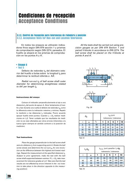
• Ensayo 5<br />
• Test 5<br />
Defecto de redondez t 5 del diámetro exterior<br />
del husillo a bolas sobre la longitud l 5 para<br />
determinar la rectitud referida a AA’.<br />
l5 l5 l5<br />
d o<br />
Radial run-out t 5 of ball screw shaft outer<br />
diameter for determining straightness related<br />
to AA’ per length l 5 .<br />
2 d o<br />
A<br />
l1<br />
A´<br />
2 d o<br />
Instrucciones del ensayo<br />
t5p<br />
A<br />
l5<br />
l5<br />
t5max<br />
A´<br />
Colocar el indicador perpendicularmente al eje a una<br />
distancia l 5 del punto de apoyo A. Girar lentamente el husillo<br />
y leer durante una vuelta el defecto de redondez t 5a como<br />
la diferencia entre la indicación máxima y mínima. Repetir<br />
la medición a las distancias l 5 indicadas. Previo acuerdo<br />
apoyar husillo entre puntos. Cuando l 1 < 2l 5 realizar mediciones<br />
en l 1 /2. Tener cuidado que los resultados de medición<br />
no se vean afectados por otros errores inherentes a la<br />
tuerca (girar siempre en sentido contrario a la posición de<br />
medición).<br />
Test Instructions<br />
Tab.12<br />
d 0<br />
Fig. 28<br />
> <<br />
6<br />
12<br />
25<br />
50<br />
100<br />
12<br />
25<br />
50<br />
100<br />
200<br />
l 5<br />
80<br />
160<br />
315<br />
630<br />
1250<br />
t 50 (µm)<br />
tolerancia / tolerance<br />
1 3 5 7 10<br />
20 25 32 40 80<br />
20 25 32 40 80<br />
20 25 32 40 80<br />
20 25 32 40 80<br />
20 25 32 40 80<br />
Place the gauge perpendicular to the ball screw shaft<br />
axis at a distance l 5 from supporting point A. Rotate the ball<br />
screw slowly and determine the run-out t 5a for one revolution<br />
as the difference between the highest and lowest readings.<br />
Repeat the measurement at the specified distances l 5 .<br />
Subject to prior agreement, make the test with the ball<br />
screw shaft supported between centres. If l 1 < 2l 5 , take measurement<br />
for tolerance grades at l 1 /2. Take care that the test<br />
results are not affected by errors inherent in the nut (rotation<br />
to take place in the direction opposite to the measuring<br />
position).<br />
40<br />
60<br />
80<br />
Tab.13<br />
l 1 /d 0<br />
> <<br />
40<br />
60<br />
80<br />
100<br />
t 5máx. (µm) para/for l 1 >4l 5<br />
tolerancia / tolerance<br />
1 3 5 7 10<br />
40<br />
60<br />
100<br />
160<br />
50<br />
75<br />
125<br />
200<br />
64<br />
96<br />
160<br />
256<br />
80<br />
120<br />
200<br />
320<br />
160<br />
240<br />
400<br />
640<br />
28