Trumatic E 4000 / E 4000 A - Ostsee Campingpartner
Trumatic E 4000 / E 4000 A - Ostsee Campingpartner
Trumatic E 4000 / E 4000 A - Ostsee Campingpartner

Create successful ePaper yourself
Turn your PDF publications into a flip-book with our unique Google optimized e-Paper software.
Switching on the Ventilation<br />
Control panel with slide switch<br />
Set switch (a) to Ventilation and switch (b) to the desired<br />
output setting.<br />
Control panel with rotary switch<br />
Set the rotary switch to the desired output setting (e).<br />
Switching off<br />
Set the slide switch (a) or the rotary switch (d) to the centre.<br />
If the appliance is switched off after a heating phase, the fan<br />
can continue running in order to make use of the residual heat.<br />
If the appliance is not used for a prolonged period of time,<br />
mount the cowl cap, close quick-acting valve in the gas supply<br />
line and turn off gas cylinder.<br />
Green LED “Operating”<br />
(under rotary control knob)<br />
When the device is switched on (heating or ventilation), the<br />
green LED must light up (the fan is operational). If the LED<br />
does not shine, check the (main) switch. For this purpose observe<br />
respective instructions of the vehicle manufacturer.<br />
During the heating process whilst the flame is burning, the<br />
green LED shines twice as brightly. This also makes it possible<br />
to determine the instantaneous switching point of the room<br />
temperature.<br />
Fuses<br />
The device and control panel fuses are on the electronic control<br />
unit on the device.<br />
Device fuse (F1):<br />
3.15 AT – slow – (EN 60127-2-3)<br />
Control panel fuse (F3):<br />
1.6 AT – slow –<br />
The fine-wire fuse must only be replaced by a fuse of the<br />
same design.<br />
Red LED “Failure”<br />
In the event of a failure, the red LED shines. Possible causes<br />
for the failure can be e.g. no gas, insufficient combustion air,<br />
heavily soiled rotor, defective fuse etc.. Deactivate by switching<br />
off and then switching on again.<br />
Opening a window to which a window switch is attached<br />
and closing it again is the equivalent of switching the equipment<br />
off and on again at the control panel (e.g. a fault reset)!<br />
Flash operation indicates that the operating voltage is too<br />
low or too high for the appliance (charge battery, if necessary).<br />
In Germany, always notify the Truma Service Centre if problems<br />
are encountered; in other countries the relevant service<br />
partners should be contacted (see Truma Service Booklet or<br />
www.truma.com).<br />
Disposal<br />
The device must be disposed of in line with the administrative<br />
regulations of the respective country in which it is used.<br />
National regulations and laws (in Germany, for example, the<br />
End-of-life Vehicle Regulation) must be observed.<br />
16<br />
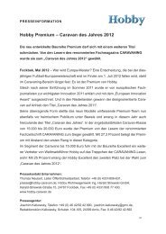
Accessories<br />
1 Control unit VG 2<br />
for heaters of driver's cabs in tank vehicles, for the transportation<br />
of hazardous goods according to ADR (not to be<br />
used in combination with a time switch).<br />
2 Outside switch AS<br />
for switching the heater on and off from the outside of the<br />
vehicle, e.g. for cargo space heaters (available with 4 m or<br />
10 m connecting cables).<br />
3 Acoustic signalling device ASM<br />
gives an acoustic signal in event of a failure.<br />
4 Time switch ZUE<br />
for pre-programming 3 switch-on times within 7 days, including<br />
4 m connecting cable (suitable for 12 V and 24 V<br />
vehicle electrical system).<br />
5 Remote sensor<br />
monitors the room temperature independent of the position<br />
of the control panel (available with 4 m or 10 m connecting<br />
cable).<br />
6 Multiple connector MSD<br />
for connecting several accessories (e.g. time switch and<br />
remote sensor).<br />
Extension cable for accessories<br />
Items 1 – 6 of 4 m or 10 m (not illustrated).<br />
7 Direct switch DIS 1<br />
for operating the heater at high setting only, without temperature<br />
control (available with 10 m connecting cable).<br />
Replaces control panel.<br />
Or direct fixed temperature switch DFS<br />
for operating the heater at a fixed temperature (40 °C – 70 °C<br />
depending on the version). Replaces the control panel.<br />
All electrical accessories are fitted with a connector and can<br />
be connected individually.