Trumatic E 4000 / E 4000 A - Ostsee Campingpartner
Trumatic E 4000 / E 4000 A - Ostsee Campingpartner
Trumatic E 4000 / E 4000 A - Ostsee Campingpartner

Create successful ePaper yourself
Turn your PDF publications into a flip-book with our unique Google optimized e-Paper software.
Fastening the heating appliance<br />
Inside installation with wall cowl or roof cowl<br />
Depending on the installation site, bolt the heating appliance<br />
securely with the fastening straps (a) or angle pieces (b)<br />
supplied.<br />
Warm air distribution and circulating air<br />
return with interior installation<br />
Warm air distribution<br />
Warm air suction apertures must be arranged in such a way<br />
that no exhaust gases from the engine or the heating device<br />
can be drawn in. It must be ensured by means of construction<br />
design that the heating air introduced into the vehicle is not<br />
polluted (e.g. by oil vapour). This is achieved, for example,<br />
with air heaters with circulating air operation, both for interior<br />
installations and for external installations. (In heaters with<br />
fresh air operation the fresh air is not to come from the engine<br />
compartment, from the vicinity of the exhaust or the exhaust<br />
outlet of the heater.)<br />
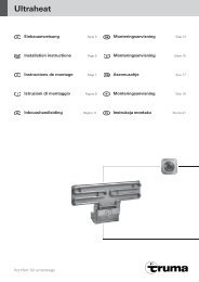
The warm air (W) is expelled from<br />
2 vents, either directly or via a<br />
warm air duct VR 72 (diameter<br />
72 mm).<br />
From the appliance to the first air outlet install only VR 72 duct<br />
(72 mm diameter) with a maximum length of approx. 1.5 m.<br />
To prevent overheating, the first air outlet must be nonsealable<br />
(swivelling vent SCW 2, end support EN-O). ÜR duct<br />
65 mm diameter) can also be laid after the first air outlet. Hot<br />
air ducts whose surface temperature exceeds 80 °C (especially<br />
as far as the first air outlet in the case of the E <strong>4000</strong>) must be<br />
protected from contact by cladding with a duct insulator (such<br />
as Truma l 80). Secure all duct connections with self-tapping<br />
screws. Fasten ducts with clamps.<br />
The warm air system is designed for each type of vehicle individually,<br />
on a modular basis. There is an extensive accessories<br />
program available (refer to brochure). Diagrams with optimum<br />
installation suggestions for warm air systems in all of the most<br />
popular motor home models can be requested free of charge<br />
via the Truma service centre.<br />
22<br />
Circulating air return<br />
The circulating air (U) is sucked directly back into the appliance.<br />
If the heating appliance is installed in a stowage compartment<br />
or similar, make an appropriately sized opening (approx, 200 cm 2 )<br />
for circulating air feedback.<br />
Do not block air ducts to heating appliance!<br />
Warm air supply and circulating air return<br />
with outside assembly<br />
Refer to installation variants Fig. 3 + 4 (Page 2).<br />
The warm air duct and recirculating air duct between the<br />
heater and the vehicle – especially in the area prone to stone<br />
demage – must be made from flexible LF air ducting or, in the<br />
protection zone, from LI air ducting (106 mm in diameter).<br />
A protective casing over the entire heater system protects it<br />
against damage and weather conditions and simultaneously<br />
serves as insulation.<br />
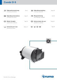
Drill two openings with a diameter<br />
of 100 mm. Apply sealing agent<br />
to flange of both connector fittings<br />
(41) and bolt to the openings<br />
on the outside. Place the grid (47)<br />
in the recirculating air duct between<br />
the suction connection fitting and<br />
the vehicle wall. Thread LFS wire<br />
clamps (42) onto the air ducts (43).<br />
Slide the air ducts over the heater<br />
connection fittings (44) and the connector<br />
fittings (41) and fasten them<br />
with the LFS wire clamps (42). Seal<br />
the joints with silicon paste.<br />
Seal hollow double walls around the<br />
air duct by putting two rolled sheet<br />
metal strips (45) or lengths of pipe<br />
between 97 an 100 mm in diameter<br />
into the openings.<br />
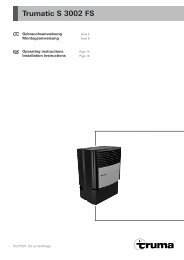
The warm air can be extended<br />
inside the vehicle using LI air duct<br />
(diameter 106 mm). To connect the<br />
air duct, fasten another connection<br />
fitting (41) into the opening.<br />
The two connector fittings can be<br />
bolted together through the wall.<br />
If you wish the warm air to be diffused inside the vehicle, an<br />
air diffuser (46) can be fitted over the warm air duct (W) with<br />
4 bolts.<br />
Do not close off or restrict the opening for the recirculating<br />
air duct!<br />
The air diffuser (46) has 2 connections for VR 72 duct (72 mm<br />
diameter), neither of which must be closed off. The protective<br />
metal sheet supplied (48) acts as a heat shield and must be<br />
securely fastened over the air diffuser (46). Stowage protection<br />
can be provided in the form of another protective metal<br />
sheet (49) fastened over the opening for the recirculating air<br />
duct (Accessory, part no. 39010-11500).<br />
The warm air system is designed for each type of vehicle individually,<br />
on a modular basis. There is an extensive accessories<br />
program available (refer to brochure). Diagrams with optimum<br />
installation suggestions for warm air systems in all of the most<br />
popular motor home models can be requested free of charge<br />
via the Truma service centre.