Trumatic E 4000 / E 4000 A - Ostsee Campingpartner
Trumatic E 4000 / E 4000 A - Ostsee Campingpartner
Trumatic E 4000 / E 4000 A - Ostsee Campingpartner

You also want an ePaper? Increase the reach of your titles
YUMPU automatically turns print PDFs into web optimized ePapers that Google loves.
The assembly instructions “Trunk compartment heating system<br />
E <strong>4000</strong> A” includes a form for the required “Confirmation<br />
of installation by a specialist company”.<br />
Notes on installation in boats<br />
Installation in boats must comply with the legal provisions of<br />
the country of use (e.g. EN ISO 10239). National specifications<br />
and regulations (in Germany, for example, DVGW Worksheet<br />
G 608) must be respected.<br />
The “Guidelines for the Construction, Installation, Testing and<br />
Operation of Liquid Gas Systems for Household Purposes on Inland<br />
Waterways” (BGR 146) must be complied with in Germany.<br />
According to these guidelines the liquid gas system must be<br />
installed by an engineer who has been approved by the inland<br />
waterways employer’s liability associations and tested by experts<br />
belonging to these employer’s liability insurance associations.<br />
In other countries always observe the respectively valid<br />
regulations.<br />
For further notes on installation, refer to the assembly instructions<br />
for the <strong>Trumatic</strong> E boat heater.<br />
Choice of location<br />
Always install the appliance and its exhaust duct in such a<br />
way that it is always easily accessible for service work and<br />
can be removed and installed easily.<br />
For evenly distributed heating, the installation of the appliance<br />
should be as much in the centre of the vehicle as possible (or<br />
under the vehicle), and in such a way that the air distribution<br />
ducts can be routed with approximately the same length.<br />
Cowls must always be fitted to prevent any waste gases entering<br />
the inside of the vehicle. The waste gas must always be<br />
guided to at least a side wall.<br />
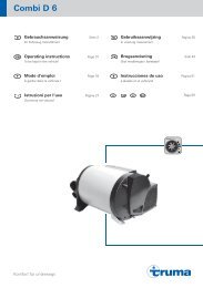
The wall cowl must be attached<br />
so that no tank supports or tank<br />
ventilation openings are found<br />
within 500 mm (R). In addition,<br />
no air discharge apertures<br />
for the living area or window<br />
openings may be located with<br />
300 mm (R) of it.<br />
When fitting the cowl within the<br />
marked area below or next to<br />
a window that must be open,<br />
an electrical window switch<br />
(part no. 3<strong>4000</strong>-85800) must<br />
be installed. The gas unit must<br />
automatically switch itself off<br />
using the Truma automatic<br />
shut-off facility if the window is<br />
opened (Accessories, part no.<br />
39050-00800).<br />
Exhaust duct<br />
20<br />
300 mm<br />
300 mm<br />
<strong>Trumatic</strong> E <strong>4000</strong> (A) heaters with wall or roof cowl must be<br />
installed only with Truma exhaust duct AA 3 (part no. 39320-00) –<br />
or Truma high-quality steel exhaust duct AEM 3 (part no.<br />
39360-00) for boats – and air intake duct ZR (part no. 39580-<br />
00), because the appliances have only been tested and approved<br />
with these ducts.<br />
R<br />
New O-rings must installed each time the appliance has<br />
been dismantled.<br />
Permitted duct lengths<br />
1. Inside installation with wall cowl<br />
(see installation variant 1, page 2):<br />
– Duct lengths up to max. 30 cm can be laid horizontally<br />
or with a downward slope up to 5 cm.<br />
– Duct lengths of up to max. 100 cm must be laid with an<br />
upward slope of at east 5 cm to the wall cowl.<br />
2. Inside installation with roof cowl<br />
(see installation variant 2, page 2):<br />
– Duct lengths of up to max. 200 cm must be routed<br />
upwards at an angle of at least 45 degrees.<br />
3. Under floor installation with wall cowl<br />
(see installation variant 4, page 2):<br />
– Duct lengths of up to 30 cm can be laid horizontally<br />
or with a downward slope of up to 5 cm. Ducts must also<br />
be protected against damage from flying stones.<br />
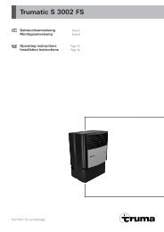
Inside installation with wall cowl set<br />
See installation variant Fig. 1 (page 2)<br />
Installation of wall cowl<br />
Install wall cowl (arrow pointing up) on an even surface around<br />
which wind can flow from all sides. Drill an opening of 83 mm<br />
diame ter (pack wood into any hol low spaces in the area of the<br />
cowl opening). Use the en closed rubber seal (8) for sealing. In<br />
the event of structured surfaces coat with plastic body sealant<br />
– do not use silicone!<br />
Slide clamp (7) over the ducts prior to passing the exhaust<br />
double duct through the opening.<br />
Slide rubber seal (8 – smooth side toward cowl, sealing<br />
lips toward wall) and clip (4) onto inner section of cowl (9).<br />
Press together end of exhaust duct (1) so that winding touches<br />
winding, and slide over O-ring (10) onto the connection<br />
fitting (11 – bend pointing up).<br />
Slide holes of clip (4) onto pins of muff (11 – screw facing<br />
downwards) and screw in place. Slide combustion air intake<br />
duct (5) on the serrated connection fitting (12).<br />
Fasten cowl inner part (9) with 6 self-tapping screws (14),<br />
mount cowl outer part (15) and fasten with 2 screws (16).<br />
Fasten combustion air intake duct with clamp (7), from the<br />
inside, on the connection fitting (12).<br />
Fasten cowl double duct to the wall with at least one clamp<br />
ZRS (17).<br />
17<br />
Ø 83 mm<br />
7<br />
5<br />
1<br />
4<br />
8<br />
10<br />
11 12<br />
9<br />
TOP OBEN<br />
15<br />
14<br />
16