NOTICE TECHNIQUE PRODUIT et de MISE EN OEUVRE ... - DEF
NOTICE TECHNIQUE PRODUIT et de MISE EN OEUVRE ... - DEF
NOTICE TECHNIQUE PRODUIT et de MISE EN OEUVRE ... - DEF

Create successful ePaper yourself
Turn your PDF publications into a flip-book with our unique Google optimized e-Paper software.
Gamme ECS Cassiopée FORTE<br />
Notice technique produit <strong>et</strong> <strong>de</strong> mise en œuvre<br />
Document : 02.NTP.1241<br />
Indice : C<br />
Date : 24/10/08<br />
Page : 32/51<br />
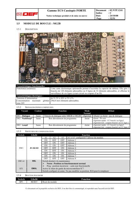
I.5 MODULE DE BOUCLE : MG2B<br />
I.5.1<br />
DESCRIPTION<br />
DS1<br />
DS2<br />
DS3<br />
J1/P1<br />
SW1-4<br />
SW1-3<br />
2<br />
1<br />
B4<br />
B3<br />
B2<br />
J2<br />
B1<br />
BP1<br />
Caractéristiques fonctionnelles<br />
Fonction(s) assurée(s) C<strong>et</strong>te carte électronique optionnelle perm<strong>et</strong> d’accroître la capacité du tableau. Elle gère 2<br />
boucles <strong>de</strong> 128 éléments adressables ou 4 lignes <strong>de</strong> 32 éléments adressables, <strong>et</strong> effectue la<br />
surveillance <strong>de</strong> ces lignes (court-circuit ou coupure d’un fil).<br />
Caractéristiques électriques :<br />
Tensions d’alimentation<br />
Consommation maximale globale<br />
sous 24V<br />
<strong>de</strong> 21.5V à 30V <strong>et</strong> 5V±1%.<br />
29mA hors éléments adressables.<br />
I.5.2 SIGNALISATIONS LUMINEUSES<br />
Voyant Couleur Fonction Mo<strong>de</strong><br />
Défaut<br />
Normal<br />
DS1 : Dialogue Jaune Témoin du dialogue entre MB2B <strong>et</strong> MG2B clignotant Allumé ou éteint : pas <strong>de</strong> dialogue<br />
DS2 : Fault/loop1 Jaune Bon déroulement du programme éteint allumé : Pb carte<br />
clignotant rapi<strong>de</strong> : CC boucle1 ou ligne1<br />
clignotant lent : coupure boucle1 ou CC ligne 2<br />
DS3 : Loop2 Jaune Bon déroulement du programme éteint clignotant rapi<strong>de</strong> : CC boucle2 ou ligne3<br />
clignotant lent : coupure boucle2 ou CC ligne 4<br />
I.5.3 SWITCHES DE CONFIGURATION<br />
Switch Libellé Fonction<br />
A1 A2 A3 A1 à A3 configurent l’adresse du module.<br />
ON OFF OFF Adresse 1<br />
OFF ON OFF Adresse 2<br />
ON ON OFF Adresse 3<br />
SW1 A1-A2-A3 OFF OFF ON Adresse 4<br />
ON OFF ON Adresse 5<br />
OFF ON ON Adresse 6<br />
ON ON ON Adresse 7<br />
OFF OFF OFF Adresse 8<br />
SW1-4 BSL Switch <strong>de</strong>stiné à la maintenance.<br />
‣ Norm : Position en fonctionnement normal.<br />
‣ Prog : position incorrecte – carte non fonctionnelle<br />
ST1 EMUL Active le chien <strong>de</strong> gar<strong>de</strong> du microcontrôleur IC7.<br />
Switch configuré en usine. Ne pas modifier sa position. R24 peut le remplacer<br />
I.5.4 BOUTON POUSSOIR<br />
Switch Libellé Fonction<br />
BP1 RESET Res<strong>et</strong> du module<br />
ST1<br />
Ce document est la propriété exclusive <strong>de</strong> <strong>DEF</strong>, il ne doit être ni communiqué, ni reproduit sans l'accord écrit <strong>de</strong> <strong>DEF</strong>.