Notice TATOU Digital - Atlantic-comfort.com
Notice TATOU Digital - Atlantic-comfort.com
Notice TATOU Digital - Atlantic-comfort.com

Create successful ePaper yourself
Turn your PDF publications into a flip-book with our unique Google optimized e-Paper software.
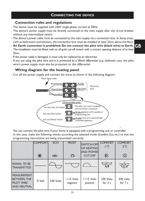
Wiring diagram for the heating panel<br />
- Cut off the power supply and connect the wires as shown in the following diagram:<br />
Panel heater cable<br />
CONNECTING THE DEVICE<br />
Connection rules and regulations<br />
- The device must be supplied with 230V single-phase current at 50Hz.<br />
- The device’s power supply must be directly connected to the main supply after the circuit breaker<br />
without any intermediate switch.<br />
- The device’s power cable must be connected to the main supply via a connection box. In damp areas,<br />
such as bathrooms and kitchens, the connection box must be installed at least 25cm above the floor.<br />
- An Earth connection is prohibited. Do not connect the pilot wire (black wire) to Earth. GB<br />
- The installation must be fitted with an all-pole cut-off switch with a contact opening distance of at least<br />
3mm.<br />
- If the power cable is damaged, it must only be replaced by an electrician.<br />
- If you are using the pilot wire and it is protected by a 30mA differential (e.g.: bathroom use), the pilot<br />
wire’s power supply must also be protected on this differential.<br />
Phase=brown<br />
Neutral=blue<br />
Pilot wire=Black<br />
PHASE<br />
NEUTRAL<br />
Electricity<br />
grid<br />
1st case: only one heater<br />
2nd case: Slave heater<br />
3rd case: Master heater<br />
Three possible cases<br />
-<br />
You can connect the pilot wire if your home is equipped with a programming unit or controller.<br />
In this case, make the following checks according the selected mode (Comfort, Eco, etc.) to that the<br />
programming instructions are being transmitted correctly:<br />
COMFORT ECO FROST<br />
The pilot wire end is insulated<br />
and not further connected<br />
To the appliance with cassette or<br />
programming unit.<br />
To pilot wire of an electronically<br />
controlled appliance<br />
SWITCH-OFF<br />
OF HEATING<br />
AND POWER<br />
CUT-OFF<br />
COMFORT<br />
-1°C<br />
COMFORT<br />
-2°C<br />
SIGNAL TO BE<br />
TRANSMITTED<br />
5'<br />
3''<br />
5'<br />
7''<br />
MEASUREMENT<br />
BETWEEN THE<br />
PILOT WIRE<br />
AND NEUTRAL<br />
0Volt<br />
230 Volts<br />
-115 Volts<br />
negative<br />
+115 Volts<br />
positive<br />
230 Volts<br />
for 3 s<br />
230 volts<br />
for 7 s<br />
31