You also want an ePaper? Increase the reach of your titles
YUMPU automatically turns print PDFs into web optimized ePapers that Google loves.
13<br />
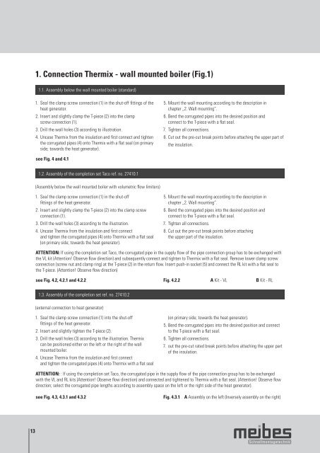
1. Connection <strong>Thermix</strong> - wall mounted boiler (Fig.1)<br />
1.1. Assembly below the wall mounted boiler (standard)<br />
1. Seal the clamp screw connection (1) in the shut-off fittings of the<br />
heat generator.<br />
2. Insert and slightly clamp the T-piece (2) into the clamp<br />
screw connection (1).<br />
3. Drill the wall holes (3) according to illustration.<br />
4. Uncase <strong>Thermix</strong> from the insulation and first connect and tighten<br />
the corrugated pipes (4) onto <strong>Thermix</strong> with a flat seal (on primary<br />
side; towards the heat generator).<br />
see Fig. 4 and 4.1<br />
1.2. Assembly of the completion set Taco ref. no. 27410.1<br />
(Assembly below the wall mounted boiler with volumetric flow limiters)<br />
1. Seal the clamp screw connection (1) in the shut-off<br />
fittings of the heat generator.<br />
2. Insert and slightly clamp the T-piece (2) into the clamp screw<br />
connection (1).<br />
3. Drill the wall holes (3) according to the illustration.<br />
4. Uncase <strong>Thermix</strong> from the insulation and first connect<br />
and tighten the corrugated pipes (4) onto <strong>Thermix</strong> with a flat seal<br />
(on primary side; towards the heat generator).<br />
5. Mount the wall mounting according to the description in<br />
chapter „2. Wall mounting“.<br />
6. Bend the corrugated pipes into the desired position and<br />
connect to the T-piece with a flat seal.<br />
7. Tighten all connections.<br />
<strong>8.</strong> Cut out the pre-cut break points before attaching the upper part of<br />
the insulation.<br />
5. Mount the wall mounting according to the description in<br />
chapter „2. Wall mounting“.<br />
6. Bend the corrugated pipes into the desired position and<br />
connect to the T-piece with a flat seal.<br />
7. Tighten all connections.<br />
<strong>8.</strong> Cut out the pre-cut break points before attaching<br />
the upper part of the insulation.<br />
ATTENTION: If using the completion set Taco, the corrugated pipe in the supply flow of the pipe connection group has to be exchanged with<br />
the VL kit (Attention! Observe flow direction) and subsequently connect and tighten to <strong>Thermix</strong> with a flat seal. Remove lower clamp screw<br />
connection (screw nut and clamp ring) at the T-piece (2) in the return flow. Insert push-in socket (5) and connect the RL kit with a flat seal to<br />
the T-piece. (Attention! Observe flow direction)<br />
see Fig. 4.2, 4.2.1 and 4.2.2 Fig. 4.2.2 A Kit - VL B Kit - RL<br />
1.3. Assembly of the completion set ref. no. 27410.2<br />
(external connection to heat generator)<br />
1. Seal the clamp screw connection (1) into the shut-off<br />
fittings of the heat generator.<br />
2. Insert and slightly tighten the T-piece (2).<br />
3. Drill the wall holes (3) according to the illustration. <strong>Thermix</strong><br />
can be positioned either on the left or the right of the wall<br />
mounted boiler.<br />
4. Uncase <strong>Thermix</strong> from the insulation and first connect<br />
and tighten the corrugated pipes (4) onto <strong>Thermix</strong> with a flat seal<br />
(on primary side; towards the heat generator).<br />
5. Bend the corrugated pipes into the desired position and connect<br />
to the T-piece with a flat seal.<br />
6. Tighten all connections.<br />
7. out the pre-cut rated break points before attaching the upper part<br />
of the insulation.<br />
ATTENTION: : If using the completion set Taco, the corrugated pipe in the supply flow of the pipe connection group has to be exchanged<br />
with the VL and RL kits (Attention! Observe flow direction) and connected and tightened to <strong>Thermix</strong> with a flat seal. (Attention! Observe flow<br />
direction; select the corrugated pipe lengths according to assembly space on the left or the right side of the heat generator).<br />
see Fig. 4.3, 4.3.1 and 4.3.2 Fig. 4.3.1 A Assembly on the left (Inversely assembly on the right)


