
You also want an ePaper? Increase the reach of your titles
YUMPU automatically turns print PDFs into web optimized ePapers that Google loves.
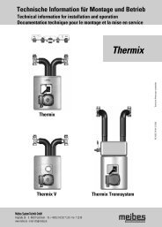
<strong>8.</strong> <strong>Thermix</strong> V with thermostatic temperature regulation<br />
Setting of the preliminary heat temperature of the mixed heating circuit at the thermostat head:<br />
Thermostat setting Preliminary temperature of the mixed heating circuit<br />
* ca. 25°C<br />
1 ca. 30°C<br />
2 ca. 35°C<br />
3 ca. 40°C<br />
4 ca. 45°C<br />
5 ca. 50°C<br />
see Fig. 9 A Bypass primary (must remain closed for proper functioning)<br />
<strong>8.</strong> <strong>Thermix</strong> V (Fig.3)<br />
B Bypass secondary (see item 3.2)<br />
C Temperature sensor<br />
D Thermostatically regulated injection valve (for setting, see table)<br />
Setting the volumetric flow rates / hydraulic alignment between mixed and unmixed circuit:<br />
see Fig. D3 A Volumetric flow - pressure Loss diagram -<strong>Thermix</strong> V<br />
B Pressure loss (bar)<br />
C Volumetric flow [l/h]<br />
The necessary volumetric flow rate for the unmixed heating circuit results from its heat requirement. The necessary flow volume for the mixed<br />
heating circuit and the required pump level of the <strong>Thermix</strong> pump are to be taken from the enclosed table in accordance with the heating<br />
requirements.<br />
Requirement for presetting both volumetric flow rates:<br />
1. All radiator valves in the unmixed circuit must be set to maximum flow-rate<br />
2. The injection valve on <strong>Thermix</strong> is completely open (setting 5 on the thermostat head).<br />
3. The pump on <strong>Thermix</strong> is switched on.<br />
The flow volume is adjusted on the individual flow meters as follows:<br />
1. Set the established pump level on <strong>Thermix</strong> pump.<br />
2. Set the volumetric flow rate established for the mixed circuit using the compensation valve.<br />
3. Carry out the fine-tuning of both compensation valves until the stated volumetric flow rates are set.<br />
Should there be an increase in the head load/demand, set <strong>Thermix</strong> pump to the next highest level and perform the adjustment once again. All<br />
modifications of the heating requirement (e.g. in case of an extension of the floor heating area) require a renewed setting of the volumetric<br />
rates.<br />
20<br />
GB