
You also want an ePaper? Increase the reach of your titles
YUMPU automatically turns print PDFs into web optimized ePapers that Google loves.
19<br />
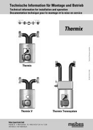
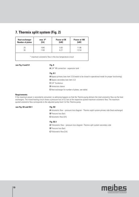
7. <strong>Thermix</strong> split system (Fig. 2)<br />
Heat exchanger<br />
Number of plates<br />
20<br />
30<br />
max. V*<br />
[l/h]<br />
1040<br />
1100<br />
Power at 5K<br />
[kW]<br />
5.93<br />
6.27<br />
* maximum volumetric flow in the low temperature circuit<br />
Power at 10K<br />
[kW]<br />
see Fig. 8 and <strong>8.</strong>1 Fig. 8<br />
A 3/4“ MI connection - expansion tank<br />
11.86<br />
12.54<br />
Fig. <strong>8.</strong>1<br />
A Bypass primary (see item 3.3) (needs to be closed in operational mode for proper functioning)<br />
B Bypass secondary (see item 3.2)<br />
C 3/4” Eurokonus<br />
D Immersion sleeve<br />
E Heat exchanger for number of plates, see table)<br />
Requirements:<br />
If the maximum power is secondarily consumed, no admixing happens so that the <strong>Thermix</strong> pump delivers the total volumetric flow via the heat<br />
exchangers. The mixed heating circuit shows a pressure loss of 0.2 bar at the respective quoted maximum volumetric flow. The maximum<br />
quoted volumetric flow corresponds to the adjusted pump level 3 of the <strong>Thermix</strong> pump.<br />
see Fig. D2 and D2.1 Fig. D2<br />
A Volumetric flow – pressure loss diagram - <strong>Thermix</strong> seplit system primary side (heat exchanger)<br />
B Pressure loss (bar)<br />
C Volumetric flow [l/h]<br />
Fig. D2.1<br />
A FVolumetric flow – pressure loss diagram -<strong>Thermix</strong> split system secondary side<br />
B Pressure loss (bar)<br />
C FVolumetric flow [l/h]