- Page 1 and 2: Multilingual VersionEnglishFrançai
- Page 3 and 4: IMPORTANT SAFEGUARDCAUTIONRISK OF E
- Page 5 and 6: TABLE OF CONTENTS1. HARDWARE OVERVI
- Page 7 and 8: HARDWARE OVERVIEW1. HARDWARE OVERVI
- Page 9: HARDWARE OVERVIEWNote: It’s not s
- Page 13 and 14: CONNECTION AND SETUP2.4 DVR Power O
- Page 15 and 16: CONNECTION AND SETUP2.8 Examining D
- Page 17 and 18: USER INTERFACE3.1.2 Channel Status.
- Page 19 and 20: FREQUENTLY-USED FUNCTIONS4. FREQUEN
- Page 21 and 22: FREQUENTLY-USED FUNCTIONSHow to go
- Page 23 and 24: FREQUENTLY-USED FUNCTIONSNote: It
- Page 25 and 26: MAIN MENU5. MAIN MENU5.1 QUICK STAR
- Page 27 and 28: MAIN MENU5.1.3 DAYLIGHTQUICK STARTG
- Page 29 and 30: 5.2.3 SYSTEM INFOMAIN MENUSYSTEMACC
- Page 31 and 32: MAIN MENU7) BACKUPClick “SUBMIT
- Page 33 and 34: MAIN MENU5.3 EVENT INFORMATION5.3.1
- Page 35 and 36: MAIN MENU5.4 ADVANCED CONFIG5.4.1 C
- Page 37 and 38: MAIN MENU6) ALARM BUZZERSelect to e
- Page 39 and 40: MAIN MENUFTPWhen this function is e
- Page 41 and 42: MAIN MENU5) HDD DISPLAY MODESelect
- Page 43 and 44: MAIN MENU5.4.8 DCCSNote: This funct
- Page 45 and 46: MAIN MENU7) SCENE CHANGESelect “O
- Page 47 and 48: IVS STATISTICSMAIN MENUPress “LIS
- Page 49 and 50: MAIN MENUNote: For details about DV
- Page 51 and 52: How to check video recordingMAIN ME
- Page 53 and 54: REMOTE OPERATION6. REMOTE OPERATION
- Page 55 and 56: Full Function VersionREMOTE OPERATI
- Page 57 and 58: REMOTE OPERATIONTo immediately play
- Page 59 and 60: REMOTE OPERATIONNote: Before using
- Page 61 and 62:
REMOTE OPERATIONIconDescriptionThe
- Page 63 and 64:
To edit or remove a certain level o
- Page 65 and 66:
REMOTE OPERATIONIconChannel Control
- Page 67 and 68:
REMOTE OPERATION6.2.2 IVS Statistic
- Page 69 and 70:
APPENDIX 1 SPECIFICATIONS GeneralDa
- Page 71 and 72:
APPENDIX 3 PUSH VIDEO CONFIGURATION
- Page 73 and 74:
APPENDIX 3 PUSH VIDEO CONFIGURATION
- Page 75 and 76:
APPENDIX 4 MOBILE SURVEILLANCE VIA
- Page 77 and 78:
APPENDIX 5 SET PUSH VIDEOA5.2.2 Fro
- Page 79 and 80:
APPENDIX 7 COMPATIBLE SATA HDD LIST
- Page 81 and 82:
SCHEDULE SETTING*For selected model
- Page 83 and 84:
DVR FULL D1Manuel de l’utilisateu
- Page 85 and 86:
Licence MPEG4LA LICENCE COUVRE L’
- Page 87 and 88:
5.3.1 RECH RAPIDE .................
- Page 89 and 90:
PRÉSENTATION DU MATÉRIEL11) (▲
- Page 91 and 92:
CONNEXION ET CONFIGURATION2. CONNEX
- Page 93 and 94:
CONNEXION ET CONFIGURATIONTordez le
- Page 95 and 96:
CONNEXION ET CONFIGURATION2.7 Régl
- Page 97 and 98:
INTERFACE UTILISATEUR3.1.2 État de
- Page 99 and 100:
FONCTIONS UTILISÉES FRÉQUEMENT4.
- Page 101 and 102:
FONCTIONS UTILISÉES FRÉQUEMENTCom
- Page 103 and 104:
FONCTIONS UTILISÉES FRÉQUEMENT4.6
- Page 105 and 106:
MENU PRINCIPALRemarque : La section
- Page 107 and 108:
MENU PRINCIPALde configuration actu
- Page 109 and 110:
MENU PRINCIPALConvertir le format d
- Page 111 and 112:
MENU PRINCIPAL4) TYPE EVENEMENTChoi
- Page 113 and 114:
MENU PRINCIPAL6) ZONECliquez sur «
- Page 115 and 116:
MENU PRINCIPALEntrez l’adresse IP
- Page 117 and 118:
MENU PRINCIPAL•(Facultatif) Entre
- Page 119 and 120:
5.4.7 PERIPHERIQUESMENU PRINCIPALPA
- Page 121 and 122:
MENU PRINCIPAL3) AFFICHAGE LIGNESé
- Page 123 and 124:
MENU PRINCIPALSTATISTIQUES IVSAppuy
- Page 125 and 126:
MENU PRINCIPAL5.4.10 NOTIFIÉVous p
- Page 127 and 128:
VIDEO MAILMENU PRINCIPALRemarque :
- Page 129 and 130:
FONCTIONNEMENT À DISTANCE6. FONCTI
- Page 131 and 132:
Version avec fonctions complètesNo
- Page 133 and 134:
FONCTIONNEMENT À DISTANCEPour lire
- Page 135 and 136:
FONCTIONNEMENT À DISTANCERemarque
- Page 137 and 138:
FONCTIONNEMENT À DISTANCEIcôneDes
- Page 139 and 140:
Pour éditer ou retirer un certain
- Page 141 and 142:
FONCTIONNEMENT À DISTANCEIcôneCha
- Page 143 and 144:
FONCTIONNEMENT À DISTANCE6.2.2 Sta
- Page 145 and 146:
ANNEXE 1 CARACTÉRISTIQUESSource d
- Page 147 and 148:
ANNEXE 3 CONFIGURATION PUSH VIDEOAN
- Page 149 and 150:
ANNEXE 4 SURVEILLANCE MOBILE VIA EA
- Page 151 and 152:
ANNEXE 5 CONFIGURER PUSH VIDEOANNEX
- Page 153 and 154:
ANNEXE 6 LISTE DES LECTEURS FLASH U
- Page 155 and 156:
ANNEXE 8 STRUCTURE DU MENU PRINCIPA
- Page 157 and 158:
ANNEXE 9 DVR REMPLACEMENT DE PILEAN
- Page 159 and 160:
INSTRUCCIONES IMPORTANTES DE SEGURI
- Page 161 and 162:
ÍNDICE1. INFORMACIÓN GENERAL DEL
- Page 163 and 164:
INFORMACIÓN GENERAL DEL HARDWARE1.
- Page 165 and 166:
INFORMACIÓN GENERAL DEL HARDWARE7)
- Page 167 and 168:
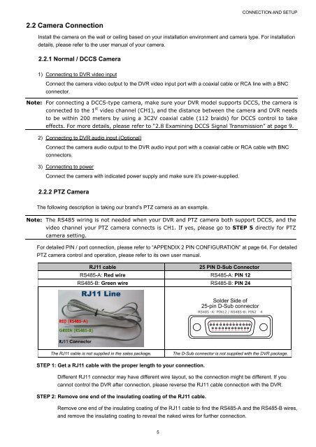
CONNECTION AND SETUP2.2 Conexión d
- Page 169 and 170:
CONNECTION AND SETUP2.5 Configuraci
- Page 171 and 172:
INTERFAZ DE USUARIO3. INTERFAZ DE U
- Page 173 and 174:
INTERFAZ DE USUARIO3.4 Menú Princi
- Page 175 and 176:
FUNCIONES UTILIZADAS FRECUENTEMENTE
- Page 177 and 178:
4.4.2 BUSQ. EVENTOFUNCIONES UTILIZA
- Page 179 and 180:
MENÚ PRINCIPAL5. MENÚ PRINCIPAL5.
- Page 181 and 182:
APPENDIX 5 SET PUSH VIDEO5.2 SISTEM
- Page 183 and 184:
APPENDIX 5 SET PUSH VIDEO5.2.4 RESP
- Page 185 and 186:
APPENDIX 5 SET PUSH VIDEO5.3 INFORM
- Page 187 and 188:
APPENDIX 5 SET PUSH VIDEO2) COV.Sel
- Page 189 and 190:
APPENDIX 5 SET PUSH VIDEO5.4.4 REDR
- Page 191 and 192:
E-MAILAPPENDIX 5 SET PUSH VIDEOCuan
- Page 193 and 194:
APPENDIX 5 SET PUSH VIDEONota: Para
- Page 195 and 196:
APPENDIX 5 SET PUSH VIDEO2) MENUHag
- Page 197 and 198:
APPENDIX 5 SET PUSH VIDEOPaso 2: Te
- Page 199 and 200:
APPENDIX 5 SET PUSH VIDEOConfigure
- Page 201 and 202:
MENSAJE PUSHAPPENDIX 5 SET PUSH VID
- Page 203 and 204:
APPENDIX 5 SET PUSH VIDEO5.5 AJUSTE
- Page 205 and 206:
OPERACIÓN REMOTA‣ Conexión remo
- Page 207 and 208:
REMOTE OPERATION6.1.3. Funcionamien
- Page 209 and 210:
REMOTE OPERATIONFunciónFile Path (
- Page 211 and 212:
REMOTE OPERATIONCómo añadir un gr
- Page 213 and 214:
REMOTE OPERATION‣ Para un grupo d
- Page 215 and 216:
REMOTE OPERATION6.2 Navegador WebPu
- Page 217 and 218:
REMOTE OPERATION/ Close all/Close(C
- Page 219 and 220:
APÉNDICE 1 ESPECIFICACIONESAPÉNDI
- Page 221 and 222:
APÉNDICE 2 CONFIGURACIÓN DE PINAP
- Page 223 and 224:
APÉNDICE 3 CONFIGURACIÓN DEL PUSH
- Page 225 and 226:
APÉNDICE 4 VIGILANCIA MÓVIL A TRA
- Page 227 and 228:
APÉNDICE 5 CONFIGURAR PUSH VIDEOA5
- Page 229 and 230:
APÉNDICE 7 LISTA DE COMPATIBILIDAD
- Page 231 and 232:
AJUSTE DEL HORARIODESPLIEGUEGRABACI
- Page 233 and 234:
FULL D1 DVRユーザーマニュア
- Page 235 and 236:
MPEG4 に 対 する 使 用 免
- Page 237 and 238:
5.3.1 時 間 検 索 .............
- Page 239 and 240:
ハードウェアの 概 要11) (
- Page 241 and 242:
接 続 およびセットアップ
- Page 243 and 244:
接 続 およびセットアップ
- Page 245 and 246:
接 続 およびセットアップ
- Page 247 and 248:
ユーザーインタフェース3.
- Page 249 and 250:
よく 使 う 機 能4. よく 使
- Page 251 and 252:
よく 使 う 機 能プリセッ
- Page 253 and 254:
よく 使 う 機 能4.6 コンピ
- Page 255 and 256:
メインメニュークイック
- Page 257 and 258:
付 録 5 プッシュビデオの
- Page 259 and 260:
ファイルフォーマットの A
- Page 261 and 262:
付 録 5 プッシュビデオの
- Page 263 and 264:
付 録 5 プッシュビデオの
- Page 265 and 266:
付 録 5 プッシュビデオの
- Page 267 and 268:
付 録 5 プッシュビデオの
- Page 269 and 270:
付 録 5 プッシュビデオの
- Page 271 and 272:
付 録 5 プッシュビデオの
- Page 273 and 274:
付 録 5 プッシュビデオの
- Page 275 and 276:
付 録 5 プッシュビデオの
- Page 277 and 278:
付 録 5 プッシュビデオの
- Page 279 and 280:
リモート 操 作6. リモート
- Page 281 and 282:
リモート 操 作フル 機 能
- Page 283 and 284:
リモート 操 作記 録 した
- Page 285 and 286:
リモート 操 作6.1.4. E-MapVid
- Page 287 and 288:
リモート 操 作アイコン説
- Page 289 and 290:
特 定 の 階 層 のビルディ
- Page 291 and 292:
リモート 操 作アイコンCha
- Page 293 and 294:
リモート 操 作6.2.2 IVS 統
- Page 295 and 296:
付 録 1 仕 様電 源 (± 10%)
- Page 297 and 298:
付 録 3 プッシュビデオの
- Page 299 and 300:
付 録 4 EAGLEEYES 経 由 のモ
- Page 301 and 302:
付 録 5 プッシュビデオの
- Page 303 and 304:
付 録 6 互 換 性 のある USB
- Page 305 and 306:
付 録 8 メインメニュー 構
- Page 307 and 308:
付 録 9 DVR バッテリの 交
- Page 309 and 310:
WICHTIGE SICHERHEITSHINWEISEVORSICH
- Page 311 and 312:
INHALTSVERZEICHNIS1. HARDWARE ÜBER
- Page 313 and 314:
HARDWARE ÜBERSICHT1. HARDWARE ÜBE
- Page 315 and 316:
HARDWARE ÜBERSICHT7) VGAStellen Si
- Page 317 and 318:
ANSCHLUSS UND EINRICHTUNG2.2 Kamera
- Page 319 and 320:
ANSCHLUSS UND EINRICHTUNG2.5 Datums
- Page 321 and 322:
BENUTZERSCHNITTSTELLE3. BENUTZERSCH
- Page 323 and 324:
BENUTZERSCHNITTSTELLE3.4 Hauptmenü
- Page 325 and 326:
HÄUFIG BENUTZTE FUNKTIONENFunktion
- Page 327 and 328:
4.4.2 EreignissucheHÄUFIG BENUTZTE
- Page 329 and 330:
HAUPTMENÜ5. HAUPTMENÜ5.1 STARTMEN
- Page 331 and 332:
HAUPTMENÜ5.2 SYSTEM5.2.1 ACCOUNTDi
- Page 333 and 334:
HAUPTMENÜ5.2.4 BACKUP DATA (USB)Sc
- Page 335 and 336:
HAUPTMENÜ5.3 EVENT INFORMATION5.3.
- Page 337 and 338:
HAUPTMENÜ2) VERDECKTHier können S
- Page 339 and 340:
HAUPTMENÜ5.4.4 NETZWERKNETZWERK‣
- Page 341 and 342:
HAUPTMENÜE-MAILWenn diese Funktion
- Page 343 and 344:
HAUPTMENÜHinweis: Um die beste Bil
- Page 345 and 346:
HAUPTMENÜ2) MENÜKlicken Sie auf
- Page 347 and 348:
HAUPTMENÜSchritt 2: Beenden Sie di
- Page 349 and 350:
HAUPTMENÜGeben Sie alle Kriterien,
- Page 351 and 352:
PUSH NACHRICHTHAUPTMENÜBevor Sie d
- Page 353 and 354:
HAUPTMENÜ5.5 TIMER5.5.1 AUFNAHMEW
- Page 355 and 356:
FERNGESTEUERTE BEDIENUNGe) Doppelkl
- Page 357 and 358:
FERNGESTEUERTE BEDIENUNG6.1.3. Allg
- Page 359 and 360:
FERNGESTEUERTE BEDIENUNGFunktionSim
- Page 361 and 362:
FERNGESTEUERTE BEDIENUNGHinzufügen
- Page 363 and 364:
FERNGESTEUERTE BEDIENUNG‣ Für Ei
- Page 365 and 366:
FERNGESTEUERTE BEDIENUNG6.2 Webbrow
- Page 367 and 368:
FERNGESTEUERTE BEDIENUNG/ Close all
- Page 369 and 370:
ANHANG 1 SPEZIFIKATIONENANHANG 1 SP
- Page 371 and 372:
ANHANG 2 POLBELEGUNGANHANG 2 POLBEL
- Page 373 and 374:
ANHANG 3 PUSH VIDEO KONFIGURATIONA3
- Page 375 and 376:
ANHANG 4 MOBILE ÜBERWACHUNG ÜBER
- Page 377 and 378:
ANHANG 5 PUSH VIDEO EINSTELLENA5.2.
- Page 379 and 380:
ANHANG 7 KOMPATIBLE SATA HDDsANHANG
- Page 381 and 382:
TIMERDISPLAYAUFNAHMEDEVICESDCCSIVSN
- Page 383 and 384:
D1 DVR الكاملدليل الم
- Page 385 and 386:
(1)ترخيص MPEG4وأتشفير
- Page 387 and 388:
13.................................
- Page 389 and 390:
نظرة عامة على الأج
- Page 391 and 392:
نظرة عامة على الأج
- Page 393 and 394:
التوصيل والإعداد2.
- Page 395 and 396:
التوصيل والإعداد5.
- Page 397 and 398:
واجهة المستخدم3. وا
- Page 399 and 400:
واجهة المستخدم4.3 ال
- Page 401 and 402:
وظائف متكررة الاس
- Page 403 and 404:
وظائف متكررة الاس
- Page 405 and 406:
القائمة الرئيسية
- Page 407 and 408:
PUSHالملحق VIDEO 5 إعداد
- Page 409 and 410:
PUSHالملحق VIDEO 5 إعداد
- Page 411 and 412:
PUSHالملحق VIDEO 5 إعداد
- Page 413 and 414:
PUSHالملحق VIDEO 5 إعداد
- Page 415 and 416:
PUSHالملحق VIDEO 5 إعداد
- Page 417 and 418:
E9PUSHالملحق VIDEO 5 إعدا
- Page 419 and 420:
PUSHالملحق VIDEO 5 إعداد
- Page 421 and 422:
PUSHالملحق VIDEO 5 إعداد
- Page 423 and 424:
PUSHالملحق VIDEO 5 إعداد
- Page 425 and 426:
اضبط آافة المعايير
- Page 427 and 428:
PUSHالملحق VIDEO 5 إعداد
- Page 429 and 430:
PUSHالملحق VIDEO 5 إعداد
- Page 431 and 432:
FERNGESTEUERTE BEDIENUNG التوص
- Page 433 and 434:
التشغيل عن بعد3.1.6 ا
- Page 435 and 436:
التشغيل عن بعدالوظ
- Page 437 and 438:
التشغيل عن بعدآيفي
- Page 439 and 440:
التشغيل عن بعدبالن
- Page 441 and 442:
التشغيل عن بعد2.6 مت
- Page 443 and 444:
التشغيل عن بعدانقر
- Page 445 and 446:
الملحق 1 المواصفاتا
- Page 447 and 448:
PINالملحق 2 تكوينالم
- Page 449 and 450:
PUSHالملحق VIDEO 3 تكوين
- Page 451 and 452:
EAGLEEYESالملحق 4 المرا
- Page 453 and 454:
PUSHالملحق VIDEO 5 إعداد
- Page 455 and 456:
الملحق 7 قائمة الا
- Page 457 and 458:
الملحق 8 تكوين القا