D Technische Daten GB specifications Gewicht 1,5 x 1 : 0,95 kg 1,5 x 2 : 1,10 kg 1,5 x 3 : 1,20 kg Weight 1,5 x 1 : 0,95 kg 1,5 x 2 : 1,10 kg 1,5 x 3 : 1,20 kg Aufprallgeschwindigkeit WE-M : 0,02 - 6,0 m/s WS-M : 0,10 - 6,0 m/s WP-M : 0,40 - 8,0 m/s Impact Speed WE-M : 0,02 - 6,0 m/s WS-M : 0,10 - 6,0 m/s WP-M : 0,40 - 8,0 m/s Rückholfederkraft 1,5 x 1 : 50 N/min - 70 N/max 1,5 x 2 : 35 N/min - 70 N/max 1,5 x 3 : 35 N/min - 80 N/max Return spring force 1,5 x 1 : 50 N/min - 70 N/max 1,5 x 2 : 35 N/min - 70 N/max 1,5 x 3 : 35 N/min - 80 N/max Drehmoment: max. Kraft bei Benutzung der Schlüsselflächen Temperaturbereich Gehäuse Kolbenstange Lieferumfang 1,5 : 40 Nm -20°C - +80°C Brünierter Spezialstahl Gehärteter rostfreier Stahl Betriebs- u. Wartungsanleitung Torque: max. force by using the flats Temperature Housing Piston rod Included 1,5 : 40 Nm -20°C - +80°C Black finish Hardened stainless steel Instructions for use and assembly F Données Techniques I Dati tecnici Poids 1,5 x 1 : 0,95 kg 1,5 x 2 : 1,10 kg 1,5 x 3 : 1,20 kg Peso 1,5 x 1 : 0,95 kg 1,5 x 2 : 1,10 kg 1,5 x 3 : 1,20 kg Vitesse d’impact WE-M : 0,02 - 6,0 m/s WS-M : 0,10 - 6,0 m/s WP-M : 0,40 - 8,0 m/s Velocità d’impatto WE-M : 0,02 - 6,0 m/s WS-M : 0,10 - 6,0 m/s WP-M : 0,40 - 8,0 m/s Force du ressort 1,5 x 1 : 50 N/min - 70 N/max 1,5 x 2 : 35 N/min - 70 N/max 1,5 x 3 : 35 N/min - 80 N/max Forza di ritorno 1,5 x 1 : 50 N/min - 70 N/max 1,5 x 2 : 35 N/min - 70 N/max 1,5 x 3 : 35 N/min - 80 N/max Couple de serrage: max disponible en utilisant les plats 1,5 : 40 Nm Coppia di serraggio max. utilizzando le superfici piane 1,5 : 40 Nm Températures -20°C - +80°C Temperatura -20°C - +80°C Corps Acier bruni Corpo Acciaio brunito Tige de piston Acier trempé inoxydable Stelo del pistone Acciaio temprato inossidabile Inclus Instructions d’utilisation et de montage Incluso Instruzioni d‘uso e di montaggio E Datos técnicos Peso Velocidad de impacto Fuerza del muelle recuperador Par: fuerza máxima utilizando la contratuerca Temperaturas Carcasa Vástago del émbolo Incluido 1,5 x 1 : 0,95 kg 1,5 x 2 : 1,10 kg 1,5 x 3 : 1,20 kg WE-M : 0,02 - 6,0 m/s WS-M : 0,10 - 6,0 m/s WP-M : 0,40 - 8,0 m/s 1,5 x 1 : 50 N/min - 70 N/max 1,5 x 2 : 35 N/min - 70 N/max 1,5 x 3 : 35 N/min - 80 N/max 1,5 : 40 Nm -20°C - +80°C Acero especial pavonado Acero inoxidable templado Instrucciones de uso y de mantenimiento 38 www.weforma.com
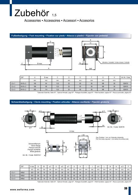
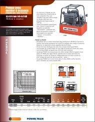
Zubehör 1,5 Accessories ▪ Accessoires ▪ Accessori ▪ Accesorios Fußbefestigung • Foot mounting • Fixation sur pieds • Attacco a piedini • Fijación con pedestal D E H F C B max G inklusive / included / inclus incluso / incluido A GW GW* A B max C D E F G H Art.-Nr. / Code mm mm mm mm mm mm mm mm 1,5 x 1 M 45 x 2 148 64 12,5 25 80 56 M8 58 S24015 1,5 x 2 M 45 x 2 198 89 12,5 25 80 56 M8 58 S24015 1,5 x 3 M 45 x 2 248 114 12,5 25 80 56 M8 58 S24015 *Optionale Gewinde: Seite 6/7 - Optional threads: page 6/7 - Filetages facultatifs: page 6/7 - Filetti facoltativi: pagina 6/7 - Rosca opcionales: página 6/7 Schwenkbefestigung • Clevis mounting • Fixation articulée • Attacco oscillante • Fijación giratoria D ø C ø C D ø E ø E ø F B B1 Art.-Nr. / Code: S24016 A max G H Zug: Endstop 1 mm vor Hubende notwendig Pull: End stop required 1 mm before the stroke ends Schwenkflansch Clevis flange Flasque articulé Flangia oscillante Brida giratoria Art.-Nr. / Code: S24016-1 N ø O M L P I J ø K GW* A max B B1 ø C D ø E ø F G H I J ø K L M N ø O P mm mm mm mm mm mm mm mm mm mm mm mm mm mm mm mm mm 1,5 x 1 M45x2 203 28 18 16 20 28 53 65 46 21 45 9 27 15 6 16 29 1,5 x 2 M45x2 253 28 18 16 20 28 53 65 46 21 45 9 27 15 6 16 29 1,5 x 3 M45x2 303 28 18 16 20 28 53 65 46 21 45 9 27 15 6 16 29 *Optionale Gewinde: Seite 6/7 - Optional threads: page 6/7 - Filetages facultatifs: page 6/7 - Filetti facoltativi: pagina 6/7 - Rosca opcionales: página 6/7 www.weforma.com 39
- Page 2 and 3: Antworten Answers ▪ Réponses ▪
- Page 4 and 5: Inhalt Index ▪ Sommaire ▪ Indic
- Page 6 and 7: Gewinde M4x0,35 - M30x1,5 Thread
- Page 8 and 9: Berechnung Selection ▪ Donnees de
- Page 10 and 11: G MASSE MIT MOTORANTRIEB ▪ MASS W
- Page 12 and 13: Grundlagen Fundamentals ▪ Princip
- Page 14 and 15: i-Mega-Line Einstellung der Dämpfu
- Page 16 and 17: ProSurf Oberflächenschutz ▪ Surf
- Page 18 and 19: Mega-Line M4 - M12 Stoßdämpfer
- Page 20 and 21: Mega-Line 0,1 - 0,2 Stoßdämpfer
- Page 22 and 23: D Technische Daten GB specification
- Page 24 and 25: Mega-Line 0,25 - 0,5 Stoßdämpfer
- Page 26 and 27: D Technische Daten GB specification
- Page 28 and 29: Mega-Line 1,0 Stoßdämpfer ▪ Sho
- Page 30 and 31: D Technische Daten GB specification
- Page 32 and 33: Mega-Line 1,25 Stoßdämpfer ▪ Sh
- Page 34 and 35: D Technische Daten GB specification
- Page 36 and 37: Mega-Line 1,5 Stoßdämpfer ▪ Sho
- Page 40 and 41: Mega-Line 2,0 Stoßdämpfer ▪ Sho
- Page 42 and 43: D Technische Daten GB specification
- Page 44 and 45: Zubehör 1,25 - 2,0 Accessories ▪
- Page 46 and 47: Mega-Line 3,0 Stoßdämpfer ▪ Sho
- Page 48 and 49: D Technische Daten GB specification
- Page 50 and 51: Mega-Line 4,0 Stoßdämpfer ▪ Sho
- Page 52 and 53: D Technische Daten GB specification
- Page 54 and 55: Edelstahl Stainless Steel ▪ Gamme
- Page 56 and 57: Reinraum WRS-M / WRP-M / WRE-M Clea
- Page 58 and 59: Mega-Line PA Palettenumlaufsysteme
- Page 60 and 61: WN-M 0,1 - 1,0 Notfall ▪ Emergenc
- Page 62 and 63: WN-M 1,25 - 3,0 Notfall ▪ Emergen
- Page 64 and 65: WSK-M Kompakt ▪ Compact ▪ Compa
- Page 66 and 67: WEB-M WSB-M / WPB-M Seitenkräfte
- Page 68 and 69: WM-Z / ZG / ZD / ZE Dämpfungszylin
- Page 70 and 71: 1 Gelenkauge • Male rod clevis
- Page 72 and 73: WM-ZDK 2 Hub •Stroke • Course
- Page 74 and 75: WV-M 0,25 - 1,0 Vorschubölbremsen
- Page 76 and 77: WM-V 10 - 70 Vorschubölbremsen ▪
- Page 78 and 79: WM-VD Doppeltwirkende Vorschubölbr
- Page 80 and 81: Bedienungshinweise Mounting Instruc
- Page 82 and 83: Schwerlastdämpfer Heavy-Duty Shock
- Page 84 and 85: 2 S Berechnung Selection ▪ Donné
- Page 86 and 87: LDS Funktionsprinzip ▪ Operating
- Page 88 and 89:
LDS Schwerlastdämpfer ▪ Heavy-Du
- Page 90 and 91:
LDS 40 ø13 20 FH ø32 32 120 90 ø
- Page 92 and 93:
LDS 75 ø22 20 FH ø45 32 170 125
- Page 94 and 95:
LDS 100 ø22 40 FH ø65 47 250 197
- Page 96 and 97:
LDS 160 ø44 50 FH ø90 55 330 260
- Page 98 and 99:
HLS Funktionsprinzip ▪ Operating
- Page 100 and 101:
HLS Schwerlastdämpfer ▪ Heavy-Du
- Page 102 and 103:
HLS 75 FH Hub • Stroke • Course
- Page 104 and 105:
Oberflächenschutz Surface protecti
- Page 106 and 107:
Bedienungshinweise Mounting Instruc
- Page 108 and 109:
Aufzugsdämpfer Shock Absorber for
- Page 110 and 111:
ADS-SR Funktionsprinzip ▪ Operati
- Page 112 and 113:
ADS-SR-26 Aufzugsdämpfer ▪ Shock
- Page 114 and 115:
ADS-SR-50 Aufzugsdämpfer ▪ Shock
- Page 116 and 117:
ADS-ST Funktionsprinzip ▪ Operati
- Page 118 and 119:
ADS-ST-26 Aufzugsdämpfer ▪ Shock
- Page 120 and 121:
ADS-ST-50 Aufzugsdämpfer ▪ Shock
- Page 122 and 123:
Berechnung Selection ▪ Donnees de
- Page 124 and 125:
WRD Rotationsdämpfer ▪ Rotary Da
- Page 126 and 127:
WRD Rotationsdämpfer ▪ Rotary Da
- Page 128 and 129:
WRD Rotationsdämpfer ▪ Rotary Da
- Page 130 and 131:
WM-G Gasfedern ▪ Gas Springs ▪
- Page 132 and 133:
1 Gelenkauge • Male rod clevis
- Page 134 and 135:
WVE 8 - 32 Vereinzelungen ▪ Escap
- Page 136 and 137:
Allgemeine Geschäftsbedingungen 1.
- Page 138 and 139:
Katalog Catalogue ▪ Catalogue ▪
- Page 140:
Weforma Dämpfungstechnik GmbH Wert