- Page 1 and 2:
HauptkatalogGeneral Catalogue
- Page 3 and 4:
InhaltContentTechnischer TeilTechni
- Page 5 and 6:
InhaltInhaltSeiteEinleitung 1Inhalt
- Page 7 and 8:
InhaltInhaltToleranzen der Radialla
- Page 9 and 10:
InhaltInhaltSeiteLagerluft und Vors
- Page 11 and 12:
InhaltInhaltSeiteEinbau gepaarter u
- Page 13 and 14:
InhaltInhaltSeiteAxial-Pendelrollen
- Page 15 and 16:
Grundlagen, Bestandteilevon Wälzla
- Page 17 and 18:
Grundlagen, Bestandteilevon Wälzla
- Page 19 and 20:
LagerbauformenEinteilung der Wälzl
- Page 21 and 22:
LagerbauformenSchrägkugellagerEinr
- Page 23 and 24:
LagerbauformenZylinderrollenlagerEi
- Page 25 and 26:
LagerbauformenZweireihige Kegelroll
- Page 27 and 28:
LagerbauformenAxial-Pendelrollenlag
- Page 29 and 30:
WälzlagerbezeichnungenAllgemeinesD
- Page 31 and 32:
WälzlagerbezeichnungenR . . . Ring
- Page 33 and 34:
WälzlagerbezeichnungenNZylinderrol
- Page 35 and 36:
WälzlagerbezeichnungenIn der Praxi
- Page 37 and 38:
WälzlagerbezeichnungenLager ohne K
- Page 39 and 40:
WälzlagerbezeichnungenDie restlich
- Page 41 and 42:
WälzlagerbezeichnungenAbb. 3.7 zei
- Page 43 and 44:
WälzlagerbezeichnungenSicherungsbl
- Page 45 and 46:
LagerdatenallgemeinPolyamidkäfige:
- Page 47 and 48:
LagerdatenallgemeinDrehzahleinschr
- Page 49 and 50:
LagerdatenallgemeinMaßpläneHaupta
- Page 51 and 52:
LagerdatenallgemeinGrenzwerte für
- Page 53 and 54:
LagerdatenallgemeinGrenzwerte für
- Page 55 and 56:
LagerdatenToleranzenAllgemeinesStan
- Page 57 and 58:
LagerdatenToleranzenToleranzen der
- Page 59 and 60:
LagerdatenToleranzenToleranzen der
- Page 61 and 62:
LagerdatenToleranzenToleranzen der
- Page 63 and 64:
LagerdatenToleranzenToleranzen der
- Page 65 and 66:
LagerdatenToleranzenToleranzen der
- Page 67 and 68:
LagerdatenToleranzenToleranzen der
- Page 69 and 70:
LagerdatenToleranzenBauhöhen der N
- Page 71 and 72:
LagerdatenToleranzenToleranzen für
- Page 73 and 74:
Auswahl und Dimensionierungvon Wäl
- Page 75 and 76:
Auswahl und Dimensionierungvon Wäl
- Page 77 and 78:
P 0 = X 0 * F r + Y 0 * F a(Gl. 6.2
- Page 79 and 80:
Auswahl und Dimensionierungvon Wäl
- Page 81 and 82:
Auswahl und Dimensionierungvon Wäl
- Page 83 and 84:
Auswahl und Dimensionierungvon Wäl
- Page 85 and 86:
Auswahl und Dimensionierungvon Wäl
- Page 87 and 88:
Auswahl und Dimensionierungvon Wäl
- Page 89 and 90:
Auswahl und Dimensionierungvon Wäl
- Page 91 and 92:
Auswahl und Dimensionierungvon Wäl
- Page 93 and 94:
Auswahl und Dimensionierungvon Wäl
- Page 95 and 96:
Auswahl und Dimensionierungvon Wäl
- Page 97 and 98:
Auswahl und Dimensionierungvon Wäl
- Page 99 and 100:
Auswahl und Dimensionierungvon Wäl
- Page 101 and 102:
Gestaltungder LagerstelleIdeale Los
- Page 103 and 104:
Gestaltungder LagerstelleAbb. 7.1d)
- Page 105 and 106:
Gestaltungder LagerstelleLagerringe
- Page 107 and 108:
Gestaltungder LagerstelleWellenpass
- Page 109 and 110:
Gestaltungder LagerstelleFormgenaui
- Page 111 and 112:
Gestaltungder LagerstelleAbb. 7.2 z
- Page 113 and 114:
Gestaltungder LagerstelleEmpfohlene
- Page 115 and 116:
Gestaltungder LagerstelleEmpfohlene
- Page 117 and 118:
Gestaltungder LagerstelleWellenpass
- Page 119 and 120:
Gestaltungder LagerstelleWellenpass
- Page 121 and 122:
Gestaltungder LagerstelleGehäusepa
- Page 123 and 124:
Gestaltungder LagerstelleGehäusepa
- Page 125 and 126:
Gestaltungder LagerstelleAusführun
- Page 127 and 128:
Gestaltungder LagerstelleBeispiele
- Page 129 and 130:
Gestaltungder LagerstelleAnschlussm
- Page 131 and 132:
Gestaltungder LagerstelleAbdichtung
- Page 133 and 134:
Gestaltungder LagerstelleAbb. 7.8b)
- Page 135 and 136:
Gestaltungder LagerstelleAbb. 7.9b)
- Page 137 and 138:
Lagerluft undVorspannungAllgemeines
- Page 139 and 140:
Lagerluft undVorspannungEinfluss de
- Page 141 and 142:
Lagerluft undVorspannungBei größe
- Page 143 and 144:
Lagerluft undVorspannungZusammenhan
- Page 145 and 146:
Lagerluft undVorspannungAbb. 8.8Nut
- Page 147 and 148:
Lagerluft undVorspannungDie Höhe d
- Page 149 and 150:
Schmierungvon WälzlagernWahl des S
- Page 151 and 152:
Schmierungvon WälzlagernIn vielen
- Page 153 and 154:
Schmierungvon WälzlagernArt desVer
- Page 155 and 156:
Schmierungvon WälzlagernBei „leb
- Page 157 and 158:
Schmierungvon WälzlagernFettführu
- Page 159 and 160:
Schmierungvon WälzlagernAsymmetris
- Page 161 and 162:
Handling, Einbau und Ausbauvon Wäl
- Page 163 and 164:
Handling, Einbau und Ausbauvon Wäl
- Page 165 and 166:
Handling, Einbau und Ausbauvon Wäl
- Page 167 and 168:
Handling, Einbau und Ausbauvon Wäl
- Page 169 and 170:
Handling, Einbau und Ausbauvon Wäl
- Page 171 and 172:
Handling, Einbau und Ausbauvon Wäl
- Page 173 and 174:
Handling, Einbau und Ausbauvon Wäl
- Page 175 and 176:
Handling, Einbau und Ausbauvon Wäl
- Page 177 and 178:
Handling, Einbau und Ausbauvon Wäl
- Page 179 and 180:
Handling, Einbau und Ausbauvon Wäl
- Page 181 and 182:
Handling, Einbau und Ausbauvon Wäl
- Page 183 and 184:
Handling, Einbau und Ausbauvon Wäl
- Page 185 and 186:
Handling, Einbau und Ausbauvon Wäl
- Page 187 and 188:
Handling, Einbau und Ausbauvon Wäl
- Page 189 and 190:
ContentContentPageTechnical Section
- Page 191 and 192:
ContentContentPageBearing Data Tole
- Page 193 and 194:
ContentContentPageExamples for non-
- Page 195 and 196:
ContentContentPageApproved heating
- Page 197 and 198:
ContentContentPageSpherical Roller
- Page 199 and 200:
Basic, Componentsof Rolling Element
- Page 201 and 202:
Basic, Componentsof Rolling Element
- Page 203 and 204:
Basic, Componentsof Rolling Element
- Page 205 and 206:
Types ofRolling Element BearingsOve
- Page 207 and 208:
Types ofRolling Element BearingsFou
- Page 209 and 210:
Types ofRolling Element BearingsSph
- Page 211 and 212:
Types ofRolling Element BearingsThr
- Page 213 and 214:
Types ofRolling Element BearingsCam
- Page 215 and 216:
DesignationSystemGeneralThe designa
- Page 217 and 218:
DesignationSystemExamples for beari
- Page 219 and 220:
DesignationSystemN Cylindrical Roll
- Page 221 and 222:
DesignationSystemIn many cases seve
- Page 223 and 224:
DesignationSystemFor special applic
- Page 225 and 226:
DesignationSystemSymbols of contact
- Page 227 and 228:
DesignationSystemOH31/500Adapter sl
- Page 229 and 230:
GeneralBearing DataGeneralAs well a
- Page 231 and 232:
GeneralBearing DataShields (-Z, -2Z
- Page 233 and 234:
GeneralBearing DataGrease FillingNK
- Page 235 and 236:
GeneralBearing DataFig. 4.8d, D bea
- Page 237 and 238:
GeneralBearing DataLimit Values for
- Page 239 and 240:
GeneralBearing DataLimit Values for
- Page 241 and 242:
Bearing DataTolerancesWidth and Hei
- Page 243 and 244:
Bearing DataTolerancesTolerances fo
- Page 245 and 246:
Bearing DataTolerancesTolerances fo
- Page 247 and 248:
Bearing DataTolerancesTolerances fo
- Page 249 and 250:
Bearing DataTolerancesTolerances fo
- Page 251 and 252:
Bearing DataTolerancesTolerances fo
- Page 253 and 254:
Bearing DataTolerancesTolerances fo
- Page 255 and 256:
Bearing DataTolerancesBearing heigh
- Page 257 and 258:
Bearing DataTolerancesTolerances fo
- Page 259 and 260:
Selection ofBearing Type and Size25
- Page 261 and 262:
Selection ofBearing Type and SizeLo
- Page 263 and 264:
Selection ofBearing Type and SizeDy
- Page 265 and 266:
Selection ofBearing Type and SizeIf
- Page 267 and 268:
Selection ofBearing Type and SizeAc
- Page 269 and 270:
Selection ofBearing Type and Sizeb)
- Page 271 and 272:
Selection ofBearing Type and SizeRe
- Page 273 and 274:
Selection ofBearing Type and SizeEx
- Page 275 and 276:
Selection ofBearing Type and SizeVi
- Page 277 and 278:
Selection ofBearing Type and SizeFu
- Page 279 and 280:
Selection ofBearing Type and SizeBe
- Page 281 and 282:
Selection ofBearing Type and Size15
- Page 283 and 284:
Selection ofBearing Type and Size-
- Page 285 and 286:
Designof Bearing LocationGeneralEac
- Page 287 and 288:
Designof Bearing LocationExamples o
- Page 289 and 290:
Designof Bearing LocationSelection
- Page 291 and 292:
Designof Bearing LocationMagnitude
- Page 293 and 294:
Designof Bearing LocationForm Toler
- Page 295 and 296:
Designof Bearing LocationShaft and
- Page 297 and 298:
Designof Bearing LocationRecommende
- Page 299 and 300:
Designof Bearing LocationRecommende
- Page 301 and 302:
Designof Bearing LocationTables of
- Page 303 and 304:
Designof Bearing LocationShaft Fits
- Page 305 and 306:
Designof Bearing LocationShaft Fits
- Page 307 and 308:
Designof Bearing LocationHousing Fi
- Page 309 and 310:
Designof Bearing LocationHousing Fi
- Page 311 and 312: Designof Bearing LocationOf equal i
- Page 313 and 314: Designof Bearing LocationFig. 7.4a)
- Page 315 and 316: Designof Bearing LocationDesign Mea
- Page 317 and 318: Designof Bearing LocationExamples f
- Page 319 and 320: Designof Bearing LocationExamples f
- Page 321 and 322: Designof Bearing LocationTwo-lip se
- Page 323 and 324: BearingClearanceFor specifi c appli
- Page 325 and 326: BearingClearanceSmoothing of Matchi
- Page 327 and 328: BearingClearanceClearance of Bearin
- Page 329 and 330: BearingClearancePreloading of Beari
- Page 331 and 332: BearingClearanceRolling bearings re
- Page 333 and 334: Lubricationof Rolling BearingsGener
- Page 335 and 336: Lubricationof Rolling Bearings- red
- Page 337 and 338: Lubricationof Rolling BearingsLubri
- Page 339 and 340: Lubricationof Rolling BearingsMisci
- Page 341 and 342: Lubricationof Rolling BearingsThe v
- Page 343 and 344: Lubricationof Rolling BearingsOil L
- Page 345 and 346: Handling, Mounting andDismounting R
- Page 347 and 348: Handling, Mounting andDismounting R
- Page 349 and 350: Handling, Mounting andDismounting R
- Page 351 and 352: Handling, Mounting andDismounting R
- Page 353 and 354: Handling, Mounting andDismounting R
- Page 355 and 356: Handling, Mounting andDismounting R
- Page 357 and 358: Handling, Mounting andDismounting R
- Page 359 and 360: Handling, Mounting andDismounting R
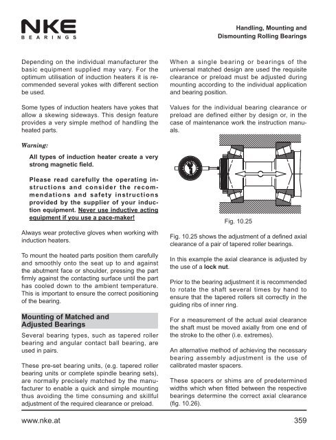
- Page 361: Handling, Mounting andDismounting R
- Page 365 and 366: Handling, Mounting andDismounting R
- Page 367 and 368: Handling, Mounting andDismounting R
- Page 369 and 370: Handling, Mounting andDismounting R
- Page 371 and 372: Handling, Mounting andDismounting R
- Page 373 and 374: 370www.nke.at
- Page 375 and 376: Einreihige RillenkugellagerSingle R
- Page 377 and 378: Einreihige RillenkugellagerSingle R
- Page 379 and 380: Einreihige RillenkugellagerSingle R
- Page 381 and 382: Einreihige RillenkugellagerSingle R
- Page 383 and 384: Einreihige RillenkugellagerSingle R
- Page 385 and 386: Einreihige RillenkugellagerSingle R
- Page 387 and 388: Einreihige RillenkugellagerSingle R
- Page 389 and 390: Einreihige RillenkugellagerSingle R
- Page 391 and 392: Einreihige RillenkugellagerSingle R
- Page 393 and 394: Einreihige RillenkugellagerSingle R
- Page 395 and 396: Einreihige RillenkugellagerSingle R
- Page 397 and 398: Einreihige RillenkugellagerSingle R
- Page 399 and 400: Einreihige RillenkugellagerSingle R
- Page 401 and 402: Einreihige RillenkugellagerSingle R
- Page 403 and 404: Einreihige RillenkugellagerSingle R
- Page 405 and 406: Einreihige RillenkugellagerSingle R
- Page 407 and 408: Einreihige RillenkugellagerSingle R
- Page 409 and 410: Einreihige RillenkugellagerSingle R
- Page 411 and 412: Einreihige RillenkugellagerSingle R
- Page 413 and 414:
Einreihige RillenkugellagerSingle R
- Page 415 and 416:
Einreihige RillenkugellagerSingle R
- Page 417 and 418:
Einreihige RillenkugellagerSingle R
- Page 419 and 420:
Einreihige RillenkugellagerSingle R
- Page 421 and 422:
Einreihige Rillenkugellager mit Rin
- Page 423 and 424:
Einreihige Rillenkugellager mit Rin
- Page 425 and 426:
Einreihige Rillenkugellager mit Rin
- Page 427 and 428:
Einreihige Rillenkugellager mit Rin
- Page 429 and 430:
Einreihige Rillenkugellager mit Rin
- Page 431 and 432:
Einreihige Rillenkugellager mit Rin
- Page 433 and 434:
Einreihige Rillenkugellager mit Rin
- Page 435 and 436:
Einreihige Rillenkugellager mit Rin
- Page 437 and 438:
Einreihige Rillenkugellager mit Rin
- Page 439 and 440:
Einreihige Rillenkugellager mit Rin
- Page 441 and 442:
438www.nke.at
- Page 443 and 444:
Einreihige SchrägkugellagerSingle
- Page 445 and 446:
Einreihige SchrägkugellagerSingle
- Page 447 and 448:
Einreihige SchrägkugellagerSingle
- Page 449 and 450:
Einreihige SchrägkugellagerSingle
- Page 451 and 452:
Einreihige SchrägkugellagerSingle
- Page 453 and 454:
Einreihige SchrägkugellagerSingle
- Page 455 and 456:
Einreihige SchrägkugellagerSingle
- Page 457 and 458:
Einreihige SchrägkugellagerSingle
- Page 459 and 460:
Einreihige SchrägkugellagerSingle
- Page 461 and 462:
Einreihige SchrägkugellagerSingle
- Page 463 and 464:
Einreihige SchrägkugellagerSingle
- Page 465 and 466:
Einreihige Schrägkugellager in Uni
- Page 467 and 468:
Einreihige Schrägkugellager in Uni
- Page 469 and 470:
Schrägkugellager, abgedichtetAngul
- Page 471 and 472:
Schrägkugellager, abgedichtetAngul
- Page 473 and 474:
Zweireihige SchrägkugellagerDouble
- Page 475 and 476:
Zweireihige SchrägkugellagerDouble
- Page 477 and 478:
Zweireihige SchrägkugellagerDouble
- Page 479 and 480:
Zweireihige SchrägkugellagerDouble
- Page 481 and 482:
Zweireihige SchrägkugellagerDouble
- Page 483 and 484:
Zweireihige SchrägkugellagerDouble
- Page 485 and 486:
Zweireihige SchrägkugellagerDouble
- Page 487 and 488:
VierpunktlagerFour-Point Contact Ba
- Page 489 and 490:
VierpunktlagerFour-Point Contact Ba
- Page 491 and 492:
VierpunktlagerFour-Point Contact Ba
- Page 493 and 494:
VierpunktlagerFour-Point Contact Ba
- Page 495 and 496:
VierpunktlagerFour-Point Contact Ba
- Page 497 and 498:
494www.nke.at
- Page 499 and 500:
PendelkugellagerSelf Aligning Ball
- Page 501 and 502:
PendelkugellagerSelf Aligning Ball
- Page 503 and 504:
PendelkugellagerSelf Aligning Ball
- Page 505 and 506:
PendelkugellagerSelf Aligning Ball
- Page 507 and 508:
PendelkugellagerSelf Aligning Ball
- Page 509 and 510:
PendelkugellagerSelf Aligning Ball
- Page 511 and 512:
PendelkugellagerSelf Aligning Ball
- Page 513 and 514:
PendelkugellagerSelf Aligning Ball
- Page 515 and 516:
PendelkugellagerSelf Aligning Ball
- Page 517 and 518:
PendelkugellagerSelf Aligning Ball
- Page 519 and 520:
PendelkugellagerSelf Aligning Ball
- Page 521 and 522:
PendelkugellagerSelf Aligning Ball
- Page 523 and 524:
PendelkugellagerSelf Aligning Ball
- Page 525 and 526:
PendelkugellagerSelf Aligning Ball
- Page 527 and 528:
PendelkugellagerSelf Aligning Ball
- Page 529 and 530:
Pendelkugellager mit SpannhülsenSe
- Page 531 and 532:
Pendelkugellager mit SpannhülsenSe
- Page 533 and 534:
Pendelkugellager mit SpannhülsenSe
- Page 535 and 536:
Pendelkugellager mit verbreitertem
- Page 537 and 538:
534www.nke.at
- Page 539 and 540:
ZylinderrollenlagerCylindrical Roll
- Page 541 and 542:
ZylinderrollenlagerCylindrical Roll
- Page 543 and 544:
ZylinderrollenlagerCylindrical Roll
- Page 545 and 546:
ZylinderrollenlagerCylindrical Roll
- Page 547 and 548:
ZylinderrollenlagerCylindrical Roll
- Page 549 and 550:
ZylinderrollenlagerCylindrical Roll
- Page 551 and 552:
ZylinderrollenlagerCylindrical Roll
- Page 553 and 554:
Einreihige ZylinderrollenlagerSingl
- Page 555 and 556:
Einreihige ZylinderrollenlagerSingl
- Page 557 and 558:
Einreihige ZylinderrollenlagerSingl
- Page 559 and 560:
Einreihige ZylinderrollenlagerSingl
- Page 561 and 562:
Einreihige ZylinderrollenlagerSingl
- Page 563 and 564:
Einreihige ZylinderrollenlagerSingl
- Page 565 and 566:
Einreihige ZylinderrollenlagerSingl
- Page 567 and 568:
Einreihige ZylinderrollenlagerSingl
- Page 569 and 570:
Einreihige ZylinderrollenlagerSingl
- Page 571 and 572:
Einreihige ZylinderrollenlagerSingl
- Page 573 and 574:
Einreihige ZylinderrollenlagerSingl
- Page 575 and 576:
Einreihige ZylinderrollenlagerSingl
- Page 577 and 578:
Einreihige ZylinderrollenlagerSingl
- Page 579 and 580:
Einreihige ZylinderrollenlagerSingl
- Page 581 and 582:
Einreihige ZylinderrollenlagerSingl
- Page 583 and 584:
Einreihige ZylinderrollenlagerSingl
- Page 585 and 586:
Einreihige ZylinderrollenlagerSingl
- Page 587 and 588:
Einreihige ZylinderrollenlagerSingl
- Page 589 and 590:
Einreihige ZylinderrollenlagerSingl
- Page 591 and 592:
Einreihige ZylinderrollenlagerSingl
- Page 593 and 594:
Einreihige ZylinderrollenlagerSingl
- Page 595 and 596:
Einreihige ZylinderrollenlagerSingl
- Page 597 and 598:
Einreihige ZylinderrollenlagerSingl
- Page 599 and 600:
Einreihige ZylinderrollenlagerSingl
- Page 601 and 602:
Vollrollige ZylinderrollenlagerFull
- Page 603 and 604:
Vollrollige ZylinderrollenlagerFull
- Page 605 and 606:
Vollrollige ZylinderrollenlagerFull
- Page 607 and 608:
Vollrollige ZylinderrollenlagerFull
- Page 609 and 610:
Vollrollige ZylinderrollenlagerFull
- Page 611 and 612:
Vollrollige Zylinderrollenlager, ei
- Page 613 and 614:
Vollrollige Zylinderrollenlager, ei
- Page 615 and 616:
Vollrollige Zylinderrollenlager, ei
- Page 617 and 618:
Vollrollige Zylinderrollenlager, ei
- Page 619 and 620:
Vollrollige Zylinderrollenlager, ei
- Page 621 and 622:
Vollrollige Zylinderrollenlager, ei
- Page 623 and 624:
Vollrollige Zylinderrollenlager, ei
- Page 625 and 626:
Vollrollige Zylinderrollenlager, ei
- Page 627 and 628:
Vollrollige Zylinderrollenlager, ei
- Page 629 and 630:
Vollrollige Zylinderrollenlager, ei
- Page 631 and 632:
Vollrollige Zylinderrollenlager, zw
- Page 633 and 634:
Vollrollige Zylinderrollenlager, zw
- Page 635 and 636:
Vollrollige Zylinderrollenlager, zw
- Page 637 and 638:
Vollrollige Zylinderrollenlager, zw
- Page 639 and 640:
Vollrollige Zylinderrollenlager, zw
- Page 641 and 642:
Vollrollige Zylinderrollenlager, zw
- Page 643 and 644:
Vollrollige Zylinderrollenlager, zw
- Page 645 and 646:
Vollrollige Zylinderrollenlager, zw
- Page 647 and 648:
Vollrollige Zylinderrollenlager, zw
- Page 649 and 650:
Vollrollige Zylinderrollenlager, zw
- Page 651 and 652:
648www.nke.at
- Page 653 and 654:
Einreihige KegelrollenlagerSingle R
- Page 655 and 656:
Einreihige KegelrollenlagerSingle R
- Page 657 and 658:
Einreihige KegelrollenlagerSingle R
- Page 659 and 660:
Metrische einreihige Kegelrollenlag
- Page 661 and 662:
Metrische einreihige Kegelrollenlag
- Page 663 and 664:
Metrische einreihige Kegelrollenlag
- Page 665 and 666:
Metrische einreihige Kegelrollenlag
- Page 667 and 668:
Metrische einreihige Kegelrollenlag
- Page 669 and 670:
Metrische einreihige Kegelrollenlag
- Page 671 and 672:
Metrische einreihige Kegelrollenlag
- Page 673 and 674:
Metrische einreihige Kegelrollenlag
- Page 675 and 676:
Metrische einreihige Kegelrollenlag
- Page 677 and 678:
Metrische einreihige Kegelrollenlag
- Page 679 and 680:
Metrische einreihige Kegelrollenlag
- Page 681 and 682:
Metrische einreihige Kegelrollenlag
- Page 683 and 684:
Kegelrollenlager in ZollabmessungTa
- Page 685 and 686:
Kegelrollenlager in ZollabmessungTa
- Page 687 and 688:
Kegelrollenlager in ZollabmessungTa
- Page 689 and 690:
Metrische einreihige Kegelrollenlag
- Page 691 and 692:
Metrische einreihige Kegelrollenlag
- Page 693 and 694:
Metrische einreihige Kegelrollenlag
- Page 695 and 696:
Gepaarte metrische einreihige Kegel
- Page 697 and 698:
Gepaarte metrische einreihige Kegel
- Page 699 and 700:
IKOS Integral KegelrollenlagerTaper
- Page 701 and 702:
IKOS Integral KegelrollenlagerTaper
- Page 703 and 704:
IKOS Integral KegelrollenlagerTaper
- Page 705 and 706:
IKOS Integral KegelrollenlagerTaper
- Page 707 and 708:
IKOS Integral KegelrollenlagerTaper
- Page 709 and 710:
IKOS Integral-SprengringeSnap Rings
- Page 711 and 712:
PendelrollenlagerSpherical Roller B
- Page 713 and 714:
PendelrollenlagerSpherical Roller B
- Page 715 and 716:
PendelrollenlagerSpherical Roller B
- Page 717 and 718:
PendelrollenlagerSpherical Roller B
- Page 719 and 720:
PendelrollenlagerSpherical Roller B
- Page 721 and 722:
PendelrollenlagerSpherical Roller B
- Page 723 and 724:
PendelrollenlagerSpherical Roller B
- Page 725 and 726:
PendelrollenlagerSpherical Roller B
- Page 727 and 728:
PendelrollenlagerSpherical Roller B
- Page 729 and 730:
PendelrollenlagerSpherical Roller B
- Page 731 and 732:
PendelrollenlagerSpherical Roller B
- Page 733 and 734:
PendelrollenlagerSpherical Roller B
- Page 735 and 736:
PendelrollenlagerSpherical Roller B
- Page 737 and 738:
PendelrollenlagerSpherical Roller B
- Page 739 and 740:
PendelrollenlagerSpherical Roller B
- Page 741 and 742:
PendelrollenlagerSpherical Roller B
- Page 743 and 744:
PendelrollenlagerSpherical Roller B
- Page 745 and 746:
PendelrollenlagerSpherical Roller B
- Page 747 and 748:
PendelrollenlagerSpherical Roller B
- Page 749 and 750:
PendelrollenlagerSpherical Roller B
- Page 751 and 752:
PendelrollenlagerSpherical Roller B
- Page 753 and 754:
PendelrollenlagerSpherical Roller B
- Page 755 and 756:
PendelrollenlagerSpherical Roller B
- Page 757 and 758:
PendelrollenlagerSpherical Roller B
- Page 759 and 760:
PendelrollenlagerSpherical Roller B
- Page 761 and 762:
PendelrollenlagerSpherical Roller B
- Page 763 and 764:
PendelrollenlagerSpherical Roller B
- Page 765 and 766:
PendelrollenlagerSpherical Roller B
- Page 767 and 768:
Pendelrollenlager auf SpannhülseSp
- Page 769 and 770:
Pendelrollenlager auf SpannhülseSp
- Page 771 and 772:
Pendelrollenlager auf SpannhülseSp
- Page 773 and 774:
Pendelrollenlager auf SpannhülseSp
- Page 775 and 776:
Pendelrollenlager auf SpannhülseSp
- Page 777 and 778:
Pendelrollenlager auf SpannhülseSp
- Page 779 and 780:
Pendelrollenlager auf SpannhülseSp
- Page 781 and 782:
Pendelrollenlager auf AbziehhülseS
- Page 783 and 784:
Pendelrollenlager auf AbziehhülseS
- Page 785 and 786:
Pendelrollenlager auf AbziehhülseS
- Page 787 and 788:
Pendelrollenlager auf AbziehhülseS
- Page 789 and 790:
Pendelrollenlager auf AbziehhülseS
- Page 791 and 792:
Pendelrollenlager auf AbziehhülseS
- Page 793 and 794:
Pendelrollenlager auf AbziehhülseS
- Page 795 and 796:
Pendelrollenlager auf AbziehhülseS
- Page 797 and 798:
Pendelrollenlager auf AbziehhülseS
- Page 799 and 800:
796www.nke.at
- Page 801 and 802:
Axial-RillenkugellagerThrust Ball B
- Page 803 and 804:
Axial-RillenkugellagerThrust Ball B
- Page 805 and 806:
Axial-RillenkugellagerThrust Ball B
- Page 807 and 808:
Axial-RillenkugellagerThrust Ball B
- Page 809 and 810:
Axial-RillenkugellagerThrust Ball B
- Page 811 and 812:
Axial-Rillenkugellager, einseitig w
- Page 813 and 814:
Axial-Rillenkugellager, einseitig w
- Page 815 and 816:
Axial-Rillenkugellager, einseitig w
- Page 817 and 818:
Axial-Rillenkugellager, einseitig w
- Page 819 and 820:
Axial-Rillenkugellager, einseitig w
- Page 821 and 822:
Axial-Rillenkugellager, einseitig w
- Page 823 and 824:
Axial-Rillenkugellager, zweiseitig
- Page 825 and 826:
Axial-Rillenkugellager, zweiseitig
- Page 827 and 828:
Axial-Rillenkugellager, zweiseitig
- Page 829 and 830:
Axial-Rillenkugellager, einseitig w
- Page 831 and 832:
Axial-Rillenkugellager, einseitig w
- Page 833 and 834:
Axial-Rillenkugellager, einseitig w
- Page 835 and 836:
Axial-Rillenkugellager, einseitig w
- Page 837 and 838:
Axial-Rillenkugellager, zweiseitig
- Page 839 and 840:
Axial-Rillenkugellager, zweiseitig
- Page 841 and 842:
Axial-Rillenkugellager, zweiseitig
- Page 843 and 844:
840www.nke.at
- Page 845 and 846:
Axial-ZylinderrollenlagerCylindrica
- Page 847 and 848:
Axial-ZylinderrollenlagerCylindrica
- Page 849 and 850:
Axial-ZylinderrollenlagerCylindrica
- Page 851 and 852:
Axial-ZylinderrollenlagerCylindrica
- Page 853 and 854:
Axial-ZylinderrollenlagerCylindrica
- Page 855 and 856:
Axial-ZylinderrollenlagerCylindrica
- Page 857 and 858:
Axial-ZylinderrollenlagerCylindrica
- Page 859 and 860:
856www.nke.at
- Page 861 and 862:
Axial-PendelrollenlagerSpherical Ro
- Page 863 and 864:
Axial-PendelrollenlagerSpherical Ro
- Page 865 and 866:
Axial-PendelrollenlagerSpherical Ro
- Page 867 and 868:
Axial-PendelrollenlagerSpherical Ro
- Page 869 and 870:
Axial-PendelrollenlagerSpherical Ro
- Page 871 and 872:
Axial-PendelrollenlagerSpherical Ro
- Page 873 and 874:
Axial-PendelrollenlagerSpherical Ro
- Page 875 and 876:
Axial-PendelrollenlagerSpherical Ro
- Page 877 and 878:
874www.nke.at
- Page 879 and 880:
LaufrollenCam RollersLaufrollenNorm
- Page 881 and 882:
LaufrollenCam RollersDichtungswerks
- Page 883 and 884:
LaufrollenCam RollersLagerluftNKE L
- Page 885 and 886:
Laufrollen, zweireihigCam Rollers,
- Page 887 and 888:
Laufrollen, zweireihigCam Rollers,
- Page 889 and 890:
886www.nke.at
- Page 891 and 892:
GehäuselagereinheitenBearing Units
- Page 893 and 894:
GehäuselagereinheitenBearing Units
- Page 895 and 896:
GehäuselagereinheitenBearing Units
- Page 897 and 898:
GehäuselagereinheitenBearing Units
- Page 899 and 900:
GehäuselagereinheitenBearing Units
- Page 901 and 902:
GehäuselagereinheitenBearing Units
- Page 903 and 904:
GehäuselagereinheitenBearing Units
- Page 905 and 906:
GehäuselagereinheitenBearing Units
- Page 907 and 908:
GehäuselagereinheitenBearing Units
- Page 909 and 910:
GehäuselagereinheitenBearing Units
- Page 911 and 912:
GehäuselagerInsert bearingsHauptab
- Page 913 and 914:
GehäuselagerInsert bearingsHauptab
- Page 915 and 916:
GehäuselagerInsert bearingsHauptab
- Page 917 and 918:
GehäuselagerInsert bearingsHauptab
- Page 919 and 920:
Stehlagereinheiten, GraugussPlummer
- Page 921 and 922:
Stehlagereinheiten, GraugussPlummer
- Page 923 and 924:
Stehlagereinheiten, GraugussPlummer
- Page 925 and 926:
Stehlagereinheiten, GraugussPlummer
- Page 927 and 928:
Stehlagereinheiten, GraugussPlummer
- Page 929 and 930:
Stehlagereinheiten, GraugussPlummer
- Page 931 and 932:
Zweilochflascheinheiten, GraugussOv
- Page 933 and 934:
Zweilochflascheinheiten, GraugussOv
- Page 935 and 936:
Zweilochflascheinheiten, GraugussOv
- Page 937 and 938:
Zweilochflascheinheiten, GraugussOv
- Page 939 and 940:
Zweilochflascheinheiten, GraugussOv
- Page 941 and 942:
Vierlochflanscheinheiten, GraugussS
- Page 943 and 944:
Vierlochflanscheinheiten, GraugussS
- Page 945 and 946:
Vierlochflanscheinheiten, GraugussS
- Page 947 and 948:
Vierlochflanscheinheiten, GraugussS
- Page 949 and 950:
Runde Flanscheinheiten, GraugussRou
- Page 951 and 952:
Runde Flanscheinheiten, GraugussRou
- Page 953 and 954:
Runde Flanscheinheiten, GraugussRou
- Page 955 and 956:
Spannlagereinheiten, GraugussTake U
- Page 957 and 958:
Spannlagereinheiten, GraugussTake U
- Page 959 and 960:
Spannlagereinheiten, GraugussTake U
- Page 961 and 962:
Stehlagereinheiten, StahlblechPlumm
- Page 963 and 964:
Stehlagereinheiten, StahlblechPlumm
- Page 965 and 966:
Zweilochflanscheinheiten, Stahlblec
- Page 967 and 968:
Zweilochflanscheinheiten, Stahlblec
- Page 969 and 970:
966www.nke.at
- Page 971 and 972:
Spann- und AbziehhülsenAdapter and
- Page 973 and 974:
Spann- und AbziehhülsenAdapter and
- Page 975 and 976:
SpannhülsenAdapter SleevesWelle[mm
- Page 977 and 978:
SpannhülsenAdapter SleevesWelle[mm
- Page 979 and 980:
SpannhülsenAdapter SleevesWelle[mm
- Page 981 and 982:
SpannhülsenAdapter SleevesWelle[mm
- Page 983 and 984:
SpannhülsenAdapter SleevesWelle[mm
- Page 985 and 986:
SpannhülsenAdapter SleevesWelle[mm
- Page 987 and 988:
SpannhülsenAdapter SleevesWelle[mm
- Page 989 and 990:
SpannhülsenAdapter SleevesWelle[mm
- Page 991 and 992:
SpannhülsenAdapter SleevesWelle[mm
- Page 993 and 994:
Spann- und AbziehhülsenAdapter and
- Page 995 and 996:
AbziehhülsenWithdrawal SleevesWell
- Page 997 and 998:
AbziehhülsenWithdrawal SleevesWell
- Page 999 and 1000:
AbziehhülsenWithdrawal SleevesWell
- Page 1001 and 1002:
AbziehhülsenWithdrawal SleevesWell
- Page 1003 and 1004:
NutmutternLock NutsNutmutternNormen
- Page 1005 and 1006:
NutmutternLock NutsJe nach Größe
- Page 1007 and 1008:
NutmutternLock NutsGewindeThreadHau
- Page 1009 and 1010:
NutmutternLock NutsGewindeThreadHau
- Page 1011 and 1012:
NutmutternLock NutsGewindeThreadHau
- Page 1013 and 1014:
NutmutternLock NutsGewindeThreadHau
- Page 1015 and 1016:
NutmutternLock NutsGewindeThreadHau
- Page 1017 and 1018:
SicherungsblecheLocking WashersHaup
- Page 1019 and 1020:
ProduktverzeichnisNKE Produkte in n
- Page 1021 and 1022:
ProduktverzeichnisNKE Produkte in n
- Page 1023 and 1024:
ProduktverzeichnisNKE Produkte in n
- Page 1025 and 1026:
ProduktverzeichnisNKE Produkte in a
- Page 1027 and 1028:
ProduktverzeichnisNKE Produkte in a
- Page 1029 and 1030:
Product IndexNKE Products in Numeri
- Page 1031 and 1032:
Product IndexNKE Products in Numeri
- Page 1033 and 1034:
Product IndexNKE Products in Alphab
- Page 1035 and 1036:
Product IndexNKE Products in Alphab
- Page 1037:
NKE AUSTRIA GmbHIm Stadtgut C4,A-44


