
You also want an ePaper? Increase the reach of your titles
YUMPU automatically turns print PDFs into web optimized ePapers that Google loves.
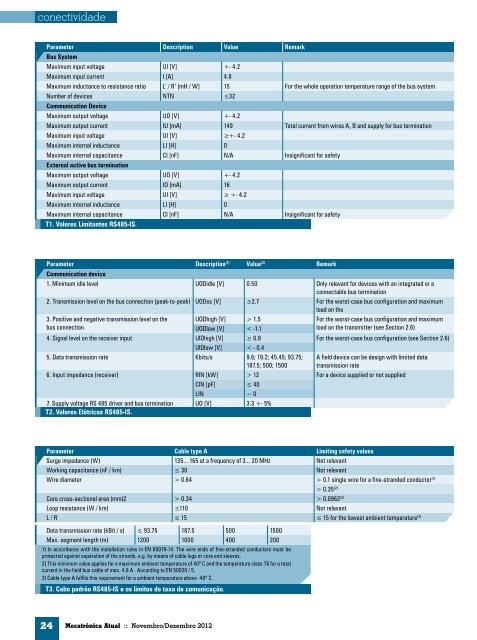
conectividade<br />
Parameter Description Value Remark<br />
Bus System<br />
Maximum input voltage UI [V] +- 4.2<br />
Maximum input current I [A] 4.8<br />
Maximum inductance to resistance ratio L’ / R’ [mH / W] 15 For the whole operation temperature range of the bus system<br />
Number of devices NTN ≤32<br />
Communication Device<br />
Maximum output voltage UO [V] +- 4.2<br />
Maximum output current IU [mA] 149 Total current from wires A, B and supply for bus termination<br />
Maximum input voltage UI [V] ≥+- 4.2<br />
Maximum internal inductance LI [H] 0<br />
Maximum internal capacitance CI [nF] N/A Insignificant for safety<br />
External active bus termination<br />
Maximum output voltage UO [V] +- 4.2<br />
Maximum output current IO [mA] 16<br />
Maximum input voltage UI [V] ≥ +- 4.2<br />
Maximum internal inductance LI [H] 0<br />
Maximum internal capacitance CI [nF] N/A Insignificant for safety<br />
T1. Valores Limitantes RS485-IS.<br />
Parameter Description (1) Value (2) Remark<br />
Communication device<br />
1. Minimum idle level UODidle [V] 0.50 Only relevant for devices with an integrated or a<br />
connectable bus termination<br />
2. Transmission level on the bus connection (peak-to-peak) UODss [V] ≥2.7 For the worst-case bus configuration and maximum<br />
load on the<br />
3. Positive and negative transmission level on the<br />
bus connection<br />
24 <strong>Mecatrônica</strong> <strong>Atual</strong> :: Novembro/Dezembro 2012<br />
UODhigh [V] > 1.5 For the worst-case bus configuration and maximum<br />
load on the transmitter (see Section 2.6)<br />
UODlow [V] < -1.1<br />
4. Signal level on the receiver input UlDhigh [V] ≥ 0.8 For the worst-case bus configuration (see Section 2.6)<br />
UlDlow [V] < - 0.4<br />
5. Data transmission rate Kbits/s 9.6; 19.2; 45.45; 93.75;<br />
187.5; 500; 1500<br />
A field device can be design with limited data<br />
transmission rate<br />
6. Input impedance (receiver) RIN [kW] > 12 For a device supplied or not supplied<br />
CIN [pF] ≤ 40<br />
LIN ~ 0<br />
7. Supply voltage RS 485 driver and bus termination<br />
T2. Valores Elétricos RS485-IS.<br />
UO [V] 3.3 +- 5%<br />
Parameter Cable type A Limiting safety values<br />
Surge impedance (W) 135... 165 at a frequency of 3... 20 MHz Not relevant<br />
Working capacitance (nF / km) ≤ 30 Not relevant<br />
Wire diameter > 0.64 > 0.1 single wire for a fine-stranded conductor (1)<br />
T3. Cabo padrão RS485-IS e os limites de taxa de comunicação.<br />
> 0.35 (2)<br />
Core cross-sectional area (mm)2 > 0.34 > 0.0962 (2)<br />
Loop resistance (W / km) ≤110 Not relavant<br />
L / R ≤ 15 ≤ 15 for the lowest ambient temperature (3)<br />
Data transmission rate (kBit / s) ≤ 93.75 187.5 500 1500<br />
Max. segment length (m) 1200 1000 400 200<br />
1) In accordance with the installation rules in EN 60079-14. The wire ends of fine-stranded conductors must be<br />
protected against separation of the strands, e.g. by means of cable lugs or core end sleeves.<br />
2) This minimum value applies for a maximum ambient temperature of 40º C and the temperature class T6 for a total<br />
current in the field bus cable of max. 4.8 A . According to EN 50020 / 5.<br />
3) Cable type A fulfils this requirement for a ambient temperature above -40º C.