
You also want an ePaper? Increase the reach of your titles
YUMPU automatically turns print PDFs into web optimized ePapers that Google loves.
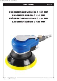
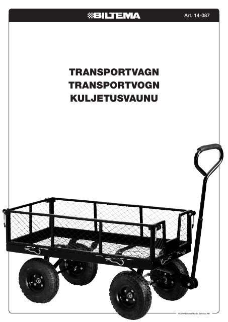
TransporTvagn<br />
TransporTvogn<br />
KuljeTusvaunu<br />
Art. 14-087<br />
© 2009 <strong>Biltema</strong> Nordic Services AB
SE<br />
TOOLS REQUIRED:<br />
Flat Head Screwdriver<br />
Two Medium Adjustable Wrenches<br />
MonTeringsanvisning<br />
verktyg:<br />
1 st. skruvmejsel med platt huvud.<br />
2 st. skiftnycklar.<br />
OBS! Dra inte åt skruvarna helt förrän vagnen är monterad.<br />
Monteringen går lättast om två personer hjälps åt.<br />
© 2009 <strong>Biltema</strong> Nordic Services AB<br />
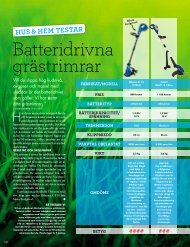
TransporTvagn<br />
Note: Do not completely tighten screws until the <strong>assembly</strong> is complete.<br />
For easier <strong>assembly</strong>, we recommend two people assemble this product.<br />
14<br />
3<br />
24<br />
15<br />
2<br />
9<br />
21<br />
11<br />
13 20<br />
5<br />
10<br />
19<br />
12<br />
22<br />
23<br />
2<br />
8<br />
19<br />
17<br />
18<br />
6<br />
7<br />
2<br />
4<br />
1<br />
16<br />
25<br />
Art. 14-087
SE<br />
5<br />
6<br />
7<br />
8<br />
9<br />
10<br />
15 Stor gaffelbricka 1<br />
16 Sprint 8<br />
17 Fjäderbricka 4<br />
18 Stor låsmutter 4<br />
19 M8 x 15 styrbult 13<br />
20 M8 x 60 bult 1<br />
21 M8 x 25 styrbult 1<br />
22 Bricka 8 mm 15<br />
23 Låsmutter 15<br />
24 Saxsprint 1<br />
25 Låsbygel 4<br />
1 Art. 14-087<br />
DeTalj<br />
1<br />
2<br />
BesKrivning 11<br />
Botten<br />
12<br />
Sidläm 13<br />
YOKE anTal<br />
1<br />
24 COTTER PIN<br />
1<br />
STEERING CONNECTOR VARNING!<br />
1<br />
1 Lasta 25 LOCK inte HANDLES(PRE-ATTACHED)<br />
mer än 250 kg på vagnen. 4 Ha<br />
alltid uppsikt över barn som hanterar vagnen. Vagnen<br />
HANDLE COUPLER 2<br />
1<br />
är inte en leksak! Placera alltid lasten jämnt på flaket.<br />
3<br />
4<br />
5<br />
6<br />
7<br />
8<br />
9<br />
Framläm 1 Pumpa inte hjulen till mer än 32 psi.<br />
Bakläm CAUTION: 1<br />
Hjul 10” x 3.50-4 4 MonTering<br />
Bakaxelstöd Do Not load the Garden 1 Cart with more than 700 lbs. Do not allow children<br />
Vänster bakaxelstag to use the cart unsupervised. 1 Bakhjul This cart is not a toy! Always distribute<br />
Delar:<br />
Höger bakaxelstag payload evenly over 1 the surface of the bed. Lower fencelrails when<br />
5 Hjul<br />
Framaxelstöd loading items onto 1the<br />
cart. Do not 6 Bakaxelstöd<br />
inflate tires more than 32 psi<br />
10 Framaxelstag 1<br />
7 Vänster bakaxelstag<br />
11<br />
12<br />
Gaffel 1<br />
8 Höger bakaxelstag<br />
Styrarm ASSEMBLY DIRECTIONS:<br />
1<br />
17 Fjäderbricka<br />
13<br />
14<br />
Handtagskoppling 1<br />
18 Stor låsmutter<br />
Carefully remove all parts from the box and place on a smooth flat surface<br />
Handtag 1<br />
BACK WHEEL ASSEMBLY:<br />
Parts needed:<br />
WHEEL 10" X 3.50-4<br />
REAR AXLE SUPPORT<br />
LEFT REAR AXLE BRACE<br />
RIGHT REAR AXLE BRACE<br />
FRONT AXLE SUPPORT<br />
CENTER FRONT AXLE BRACE<br />
#5 Wheels<br />
#6 Rear Axle Support<br />
#7 Left Rear Axle Brace<br />
#8 Right Rear Axle Brace<br />
#17 Wheel Spring Washer<br />
#18 Large lock Nuts<br />
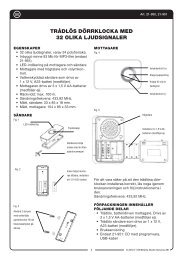
1. Passa in det vänstra och högra bakaxelstaget (7, 8) på bakaxelstödets (6) gängade stång.<br />
2. Passa in hjulen (5) på stången.<br />
3. Fäst varje hjul med en fjäderbricka och en stor låsmutter (18). Dra åt låsmuttern medsols tills hjulet sitter fast.<br />
18<br />
17<br />
1. Insert the Left and Right Axle<br />
Braces(Parts 7 and 8) onto the<br />
extended threaded poles on the Rear<br />
Axle Support(Part 6).<br />
4<br />
1<br />
1<br />
1<br />
1<br />
1<br />
2<br />
18<br />
19<br />
20<br />
21<br />
22<br />
23<br />
18 17<br />
2. Slide Wheels(Part 5) onto the extended threaded ends of the Rear Axle<br />
LARGE LOCK NUT<br />
M8 x 15 STEERING BOLTS<br />
M8 x 60 PULL HANDLE BOLT<br />
M8 x 25 STEERING BOLT<br />
FLAT WASHER 8MM<br />
LOCK NUT<br />
17<br />
3 © 2009 <strong>Biltema</strong> Nordic Services AB<br />
18<br />
4<br />
13<br />
1<br />
15<br />
15
SE<br />
Framhjul<br />
Delar:<br />
5 Hjul<br />
9 Framaxelstöd<br />
10 Framaxelstag<br />
Right Axle 11 Gaffel<br />
d 8) onto the 12 Styrarm<br />
d poles on the 15 Rear Stor gaffelbricka<br />
6). 17 Fjäderbricka<br />
18 Stor låsmutter<br />
t 5) onto the 19 extended M8 x 15 threaded styrbult ends of the Rear Axle<br />
21 M8 x 25 styrbult<br />
22 Bricka<br />
st with Wheel<br />
23<br />
Spring<br />
Låsmutter<br />
Washer(Part 17) and Large lock<br />
ten large lock 24 Nut Saxsprint clockwise until <strong>wheel</strong>s are secure.<br />
L ASSEMBLY:<br />
upport<br />
t Axle Brace<br />
k Connector<br />
Washer<br />
g Washer<br />
ut<br />
ering Bolt<br />
ering Bolt<br />
22<br />
24<br />
23<br />
Brace(Part 10), then<br />
into the second 17 hole<br />
in the Yoke(Part 11) and through the hole in the bottom of the Front Axle Support(Part<br />
4. Fäst den andra sidan av gaffeln vid stiftet på<br />
9). From the bottom, insert Washer(Part 22) and secure with Lock Nut(Part 23).<br />
undersidan av framaxelstödet med den stora<br />
Tighten clockwise until secure.<br />
gaffelbrickan (15). Lås med saxsprinten (24).<br />
3. Secure the Yoke (Part 11) to the OBS! Steering Använd Link en Connector(Part skruvmejsel med 12) by platt threading huvud one för<br />
M8 x 19 15 Bolt(Part 21 19) through att the bända first hole ut in sprintens the Yoke(Part klor så 11) att then det into går the att Link få in<br />
Connector(Part 12). Secure With en Washer(Part av dem i stiftets 22) and hål. Lock Nut(Part 23).<br />
Tighten clockwise until secure. 5. Passa in hjulen (5) på framaxelstödets (6) gängade<br />
stång.<br />
4. Attach the top of the Yoke(Part 6. Fäst 11) to varje the hjul appendage med en located fjäderbricka on the (17) under och side(top) en of<br />
15 23<br />
the Front Axle Support(Part 9) stor by first låsmutter inserting (18). Large Dra Yoke åt låsmuttern Washer(Part medsols 15) and tills then<br />
inserting Cotter Pin(Part 24) into hjulet the sitter hole in fast. the middle of the appendage.<br />
1. Fäst styrarmen (12) vid framaxelstödet NOTE: (9) Use med a flat Head Screwdriver to separate<br />
4.CONTINUED..and bend the the end end of of the the Cotter Pin Pin outwards to to lock it it into into place.<br />
två M8 x 15 styrbultar (19). Lås med bricka (22)<br />
och låsmutter (23). Dra åt medsols.<br />
3<br />
© 2009 <strong>Biltema</strong> Nordic Services AB<br />
22<br />
23<br />
18<br />
19<br />
17<br />
18<br />
18<br />
2. Join the Yoke(Part 11)<br />
and the Center Front<br />
Axle Brace(Part 10) to<br />
the Front Axle<br />
Support(Part 9) by<br />
first threading one M8<br />
x 25 Bolt(Part 21)<br />
through the hole in the<br />
Center Front Axle<br />
22<br />
23<br />
18 18<br />
1. Attach the Steering 17 17 Link<br />
Connector(Part 12) to the<br />
Front Axle Support(Part 9) by<br />
threading two M8 x 15 Bolts<br />
(Part 19) through the top of the<br />
Link connector (Part 12) and<br />
into the Axle Support(Part 9).<br />
Secure at the bottom with<br />
Washer(Part 22) and then<br />
Lock Nut(Part 23). Tighten<br />
clockwise until secure.<br />
5. 5. Slide Wheels(Part 5) 5) onto the extended<br />
threaded ends of of the Front Axle Support<br />
(Part 9). 9).<br />
6. 6. Secure Wheels first with<br />
Wheel Spring Washer(Part 17), and large lock Nut<br />
(Part 18). Tighten Large Lock Nut clockwise until <strong>wheel</strong>s are secure.<br />
BED ASSEMBLY:<br />
4<br />
21<br />
19<br />
1. Attach the Steering Link<br />
Connector(Part 12) to the<br />
Front Axle Support(Part Art. 14-087 9) by<br />
threading two M8 x 15 Bolts<br />
(Part 19) through the top of the<br />
2. Fäst gaffeln (11) och Link framaxelstaget connector (Part (10) 12) and vid framaxelstödet<br />
(9) med into en the M8 Axle x 25 Support(Part styrbult (21). 9). Lås<br />
med bricka (22) och Secure låsmutter at the bottom (23). Dra with åt medsols.<br />
Washer(Part 22) and then<br />
3. Fäst gaffeln (11) vid Lock styrarmen Nut(Part 23). (12) med Tighten en M8<br />
x 15 styrbult. Lås clockwise med bricka until (22) secure. och låsmutter<br />
(23). Dra åt medsols.<br />
19<br />
4<br />
21<br />
22<br />
24<br />
24<br />
22<br />
15 15<br />
17 17<br />
18 18
SE<br />
(Part 18). Tighten Large Lock Nut clockwise until <strong>wheel</strong>s are secure.<br />
BED ASSEMBLY:<br />
Flakbotten<br />
1 Flakbotten<br />
Parts 13 Handtagskoppling<br />
needed:<br />
14 Handtag<br />
#1<br />
19<br />
Bed<br />
M8 x 15 styrbult<br />
#13 20 Handle M8 x 60 Coupler bult<br />
#14 22 Pull Bricka Handle<br />
#19 23 M8 Låsmutter x 15 Steering Bolts<br />
#20 Färdigmonterade M8 x 60 Pull Handle framhjul Bolt<br />
Färdigmonterade bakhjul<br />
#22 Washers<br />
#23 Lock Nuts<br />
Front Wheel Assembly Back Wheel Assembly<br />
23<br />
23<br />
19<br />
19<br />
22<br />
22<br />
5<br />
Art. 14-087<br />
1. With the Bed(Part 1) turned upside down, attach the Back <strong>wheel</strong> <strong>assembly</strong><br />
1. Placera 1. flakbotten With upp-och-ner.<br />
to the the Bed Bed(Part by inserting 1) turned six upside M8 x 15 down, Steering attach Bolts(Part the Back 19) <strong>wheel</strong> from <strong>assembly</strong><br />
Fästa bakhjulen: to Passa in 2 st. M8 x 15 styrbultar (19) underifrån genom ett bottenstag och bakaxelstödet.<br />
under the Bed the by bar inserting first through six M8 the x 15 holes Steering located Bolts(Part on the metal 19) from support bars on<br />
Passa in under 4 st. M8 x 15 styrbultar (19) underifrån genom bottenstag och vänster respektive höger bakaxelstag.<br />
Lås med bricka<br />
the under the bar<br />
(22) och<br />
side first<br />
låsmutter<br />
of through the Bed the<br />
(23).<br />
then holes<br />
Dra<br />
into located the on the metal support bars on<br />
the åt medsols.<br />
holes under located side of on the both Bed the then Left into and the<br />
23<br />
holes Right located Rear Axle on both Brace( the Parts Left and<br />
23<br />
7<br />
Right and Rear 8) and Axle also Brace( the Rear Parts Axle 7 Support<br />
and (Part 8) and 6). Next also insert the Rear Washers Axle Support<br />
22<br />
(Part (Parts 6). 22) Next onto insert the Washers Bolts then<br />
22<br />
(Parts secure 22) with onto Lock the Bolts Nuts(Parts then 23).<br />
secure Tighten with Lock Lock Nuts Nuts(Parts clockwise 23). until secure.<br />
22<br />
Tighten Lock Nuts clockwise until secure.<br />
2223<br />
23<br />
19<br />
19<br />
20<br />
20<br />
19<br />
19<br />
14<br />
14<br />
5 © 2009 <strong>Biltema</strong> Nordic Services AB
SE<br />
© 2009 <strong>Biltema</strong> Nordic Services AB<br />
6<br />
Art. 14-087<br />
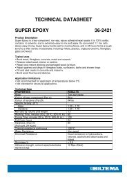
2. Fästa framhjulen: Passa in 4 st. M8 x 15 styrbultar (19) underifrån genom bottenstag och framaxelstödet (9),<br />
samt genom bottenstag och framaxelstaget (10). Lås med bricka (22) och låsmutter (23). Dra åt medsols.<br />
23<br />
23<br />
22<br />
22<br />
23<br />
22<br />
2. Join the 23 Front Wheel Assembly to the Bed(Part 1) by inserting four more M8 x<br />
15 Steering Bolts(Parts 19) first from under the bar through the holes in the<br />
22<br />
metal support bars then into the holes in both the Front Axle Support(Part 9)<br />
and the Center Front Axle Brace(Part 10). Insert Washers(Part 22) onto the<br />
2. Join the Front Wheel Assembly to the Bed(Part 1) by inserting four more M8 x<br />
3. Placera handtaget Bolts then (14) secure i handtagskopplingen with Lock Nuts(Part (13) 23). på gaffeln och fäst med M8 x 60 bulten. Lås med bricka (22)<br />
och låsmutter (23). 15 Steering Dra åt medsols. Bolts(Parts 19) first from under the bar through the holes in the<br />
3. Attach metal the support Handle bars Coupler(Part then into the 13) holes to the in end both of the the Front Pull Handle(Part Axle Support(Part 14) by 9) simply<br />
inserting and the the Center end of Front the Pull Axle Handle(Part Brace(Part 10). 14) into Insert the Washers(Part pole hole of the 22) Coupler(Part onto the 13).<br />
Be Bolts sure then to align secure holes with on Lock the inside Nuts(Part of the 23). Pull Handle(Part 14) and the outside of the<br />
Coupler(Part 13). Join to the end of the Yoke (Part 11) by aligning holes<br />
and 3. Attach then inserting the Handle M8 Coupler(Part x 60 Pull Handle 13) to Bolt(Part the end 20) of the into Pull first Handle(Part the 14) by simply<br />
Yoke, inserting the Coupler(Part the end of the 13), Pull then Handle(Part out the other 14) side into of the thepole<br />
hole of the Coupler(Part 13).<br />
Yoke. Be Secure sure to align with Washer(Part holes on the 22) inside and of Lock the Pull Handle(Part 14) and the outside of the<br />
Nut(Part Coupler(Part 23). 13). Join to the end of the Yoke (Part 11) by aligning holes<br />
and then inserting M8 x 60 Pull Handle Bolt(Part 20) into first the<br />
Yoke, the Coupler(Part 13), then out the other side of the<br />
Yoke. Secure with Washer(Part 22) and Lock<br />
23<br />
Nut(Part 23).<br />
14<br />
14<br />
7<br />
7<br />
22<br />
23<br />
22<br />
20<br />
20<br />
19<br />
19
SE<br />
FRAME ASSEMBLY:<br />
FRAME ASSEMBLY:<br />
ram<br />
2 Sidläm<br />
Parts needed:<br />
3 Framläm<br />
4 Bakläm<br />
#2 Side Panel<br />
Parts needed:<br />
16 Sprint<br />
#3 Front Panel<br />
25 Låsbygel (förmonterad) #2 #4 Side Back Panel<br />
#3 #16 Front Panel Panel Assembly Pins<br />
#4 #25 Back Lock Panel Handles<br />
#16 Panel -attached Assembly to Pins<br />
#25 Lock Front Handles and Back<br />
-attached Panels to<br />
Bed Front Assembly and Back<br />
Panels<br />
Bed Assembly<br />
8<br />
Art. 14-087<br />
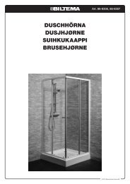
1. Join the Back Panel<br />
Färdigmonterad flakbotten.<br />
(Part 4) to the Bed<br />
1. Fäst baklämmen och sidolämmarna 1. Join (Part the 1) Back by vid inserting flakbotten Panel med<br />
hjälp av sprintarna (16). (Part two 4) Panel to the Assembly Bed Pins<br />
2. Fäst baklämmen vid sidolämmarna (Part (Part 1) 16) by genom inserting through att the dra lås-<br />
25<br />
25<br />
byglarna över krokarna. two side Panel loop Assembly located atPins<br />
3. Fäst framlämmen vid flakbotten (Part the bottom med 16) through hjälp of the av the sprin- Back<br />
16<br />
25<br />
tarna.<br />
side Panel loop and located the lop at<br />
16<br />
4. Fäst framlämmen vid sidolämmarna the edge bottom of the genom of Bed. the att Back dra<br />
låsbyglarna över krokarna. Panel and the lop<br />
3. Lift Lock 2. edge Join Handles(Part the of the side Bed. 25) that have been pre-attached to the Front and Back<br />
Panels Panels(Part up and to secure 2) the Back(Part 4) and the Side Panels(Part 2) together<br />
2. Join to by the firmly the Bed side pressing (Part 1) the Lock Handle down<br />
and around Panels(Part by inserting the hook 2) on the end of the<br />
Side Panel. to four the more Bed (Part Panel 1)<br />
by Assembly inserting Pins(Part 16)<br />
four two more per Side Panel Panel-into the loops at the bottom of the Side Panels and the<br />
25<br />
4. Repeat Assembly top the edge process Pins(Part of the with Bed. the 16)<br />
25<br />
Front two Panel(Part per Side 3), Panel-into the loops at the bottom of the Side Panels and the<br />
Panel top Assembly edge of Pins the Bed.<br />
(Part 16)<br />
and the two<br />
remaining Lock<br />
Handles<br />
(Part 25).<br />
8<br />
25<br />
25<br />
7 © 2009 <strong>Biltema</strong> Nordic Services AB<br />
25
NO<br />
TOOLS REQUIRED:<br />
MonTeringsanvisning<br />
Flat Head Screwdriver<br />
Two Medium Adjustable Wrenches<br />
Verktøy:<br />
1 stk. skrutrekker for rettspor.<br />
2 stk. skiftenøkler.<br />
OBS! Stram ikke skruene helt før vognen er montert.<br />
Monteringen går lettest om man er to personer.<br />
© 2009 <strong>Biltema</strong> Nordic Services AB<br />
TransporTvogn<br />
Note: Do not completely tighten screws until the <strong>assembly</strong> is complete.<br />
For easier <strong>assembly</strong>, we recommend two people assemble this product.<br />
14<br />
3<br />
24<br />
15<br />
2<br />
9<br />
21<br />
11<br />
13 20<br />
5<br />
10<br />
19<br />
12<br />
22<br />
23<br />
8<br />
8<br />
19<br />
17<br />
18<br />
6<br />
7<br />
2<br />
4<br />
1<br />
16<br />
25<br />
Art. 14-087
NO<br />
5<br />
6<br />
7<br />
8<br />
9<br />
10<br />
15 Stor gaffelskive 1<br />
16 Splint 8<br />
17 Fjærskive 4<br />
18 Stor låsemutter 4<br />
19 M8 x 15 styrebolt 13<br />
20 M8 x 60 bolt 1<br />
21 M8 x 25 styrebolt 1<br />
22 Skive 8 med mer 15<br />
23 Låsemutter 15<br />
24 Sakseplint 1<br />
25 Låsebøyle 4<br />
1 Art. 14-087<br />
Del<br />
1<br />
2<br />
BesKrivelse11 Bunn<br />
12<br />
Sidelem 13<br />
YOKE anTall<br />
1<br />
24 COTTER PIN<br />
1<br />
STEERING CONNECTOR ADVARSEL!<br />
1<br />
1<br />
25Last<br />
LOCK ikke HANDLES(PRE-ATTACHED)<br />
mer enn 250 kg på vognen. 4<br />
Ha alltid tilsyn med barn som håndterer vognen. Vognen<br />
HANDLE COUPLER 2<br />
1<br />
er ikke et leketøy! Plasser alltid lasten jevnt i vognbunnen.<br />
3<br />
4<br />
5<br />
6<br />
7<br />
8<br />
9<br />
Forlem 1 Pump ikke opp hjulene til mer enn 32 psi.<br />
Baklem CAUTION: 1<br />
Hjul 10” x 3.50-4 4 MonTering<br />
Bakakselstøtte Do Not load the Garden 1 Cart with more than 700 lbs. Do not allow children<br />
Venstre bakakselstag to use the cart unsupervised. 1 Bakhjul This cart is not a toy! Always distribute<br />
Deler:<br />
Høyre bakakselstag payload evenly over 1 the surface of the bed. Lower fencelrails when<br />
5 Hjul<br />
Forakselstøtte loading items onto 1the<br />
cart. Do not 6 Bakakselstøtte<br />
inflate tires more than 32 psi<br />
10 Forakselstag 1<br />
7 Venstre bakakselstag<br />
11<br />
12<br />
Gaffel 1<br />
8 Høyre bakakselstag<br />
StyrearmASSEMBLY DIRECTIONS:<br />
1<br />
17 Fjærskive<br />
13<br />
14<br />
Håndtakskobling 1<br />
18 Stor låsemutter<br />
Carefully remove all parts from the box and place on a smooth flat surface<br />
Håndtak 1<br />
BACK WHEEL ASSEMBLY:<br />
Parts needed:<br />
WHEEL 10" X 3.50-4<br />
REAR AXLE SUPPORT<br />
LEFT REAR AXLE BRACE<br />
RIGHT REAR AXLE BRACE<br />
FRONT AXLE SUPPORT<br />
CENTER FRONT AXLE BRACE<br />
#5 Wheels<br />
#6 Rear Axle Support<br />
#7 Left Rear Axle Brace<br />
#8 Right Rear Axle Brace<br />
#17 Wheel Spring Washer<br />
#18 Large lock Nuts<br />
1. Før det venstre og høyre bakakselstaget (7, 8) inn på bakakselstøttens (6) gjengede stang.<br />
2. Sett hjulene (5) på stangen.<br />
3. Fest hvert hjul med en fjærskive og en stor låsemutter (18). Stram låsemutteren med klokka til hjulet sitter fast.<br />
18<br />
17<br />
1. Insert the Left and Right Axle<br />
Braces(Parts 7 and 8) onto the<br />
extended threaded poles on the Rear<br />
Axle Support(Part 6).<br />
4<br />
1<br />
1<br />
1<br />
1<br />
1<br />
2<br />
18<br />
19<br />
20<br />
21<br />
22<br />
23<br />
18 17<br />
2. Slide Wheels(Part 5) onto the extended threaded ends of the Rear Axle<br />
LARGE LOCK NUT<br />
M8 x 15 STEERING BOLTS<br />
M8 x 60 PULL HANDLE BOLT<br />
M8 x 25 STEERING BOLT<br />
FLAT WASHER 8MM<br />
LOCK NUT<br />
17<br />
9 © 2009 <strong>Biltema</strong> Nordic Services AB<br />
18<br />
4<br />
13<br />
1<br />
15<br />
15
NO<br />
Forhjul<br />
Deler:<br />
5 Hjul<br />
9 Forakselstøtte<br />
10 Forakselstag<br />
Right Axle 11 Gaffel<br />
d 8) onto the 12 Styrearm<br />
d poles on the 15 Rear Stor gaffelskive<br />
6). 17 Fjærskive<br />
18 Stor låsemutter<br />
t 5) onto the 19 extended M8 x 15 threaded styrebolt ends of the Rear Axle<br />
21 M8 x 25 styrebolt<br />
22 Skive<br />
st with Wheel<br />
23<br />
Spring<br />
Låsemutter<br />
Washer(Part 17) and Large lock<br />
ten large lock 24 Nut Saksesplint clockwise until <strong>wheel</strong>s are secure.<br />
L ASSEMBLY:<br />
upport<br />
t Axle Brace<br />
k Connector<br />
Washer<br />
g Washer<br />
ut<br />
ering Bolt<br />
ering Bolt<br />
22<br />
24<br />
23<br />
Brace(Part 10), then<br />
into the second 17 hole<br />
in the Yoke(Part 11) and through the hole in the bottom of the Front Axle Support(Part<br />
4. Fest den andre siden av gaffelen til stiften på<br />
9). From the bottom, insert Washer(Part 22) and secure with Lock Nut(Part 23).<br />
undersiden av forakselstøtten med den store gaf-<br />
Tighten clockwise until secure.<br />
felskiven (15). Lås med saksesplinten (24). OBS!<br />
3. Secure the Yoke (Part 11) to the Bruk Steering en skrutrekker Link Connector(Part med rettspor 12) by for threading å bøye ut one<br />
M8 x 19 15 Bolt(Part 21 19) through splintens the first hole klør in slik the Yoke(Part at det går 11) an then å få en into av the dem Link inn<br />
Connector(Part 12). Secure With i stiftens Washer(Part hull. 22) and Lock Nut(Part 23).<br />
Tighten clockwise until secure. 5. Sett hjulene (5) på forakselstøttens (6) gjengede<br />
stang.<br />
4. Attach the top of the Yoke(Part 6. Fest 11) to hvert the appendage hjul med en located fjærskive on the (17) under og en side(top) stor of<br />
15 23<br />
the Front Axle Support(Part 9) låsemutter by first inserting (18). Large Stram Yoke låsemutteren Washer(Part med 15) klokka and then<br />
inserting Cotter Pin(Part 24) into til hjulet the hole sitter in the fast. middle of the appendage.<br />
1. Fest styrearmen (12) til forakselstøtten NOTE: (9) Use med a flat to Head Screwdriver to separate<br />
4.CONTINUED..and bend the the end end of of the the Cotter Pin Pin outwards to to lock it it into into place.<br />
M8 x 15 styrebolter (19). Lås med skive (22) og<br />
låsemutter (23). Trekk til med klokka.<br />
3<br />
© 2009 <strong>Biltema</strong> Nordic Services AB<br />
22<br />
23<br />
18<br />
19<br />
17<br />
18<br />
18<br />
2. Join the Yoke(Part 11)<br />
and the Center Front<br />
Axle Brace(Part 10) to<br />
the Front Axle<br />
Support(Part 9) by<br />
first threading one M8<br />
x 25 Bolt(Part 21)<br />
through the hole in the<br />
Center Front Axle<br />
22<br />
23<br />
1. Attach the Steering 17 17 Link<br />
Connector(Part 12) to the<br />
Front Axle Support(Part 9) by<br />
threading two M8 x 15 Bolts<br />
(Part 19) through the top of the<br />
Link connector (Part 12) and<br />
into the Axle Support(Part 9).<br />
Secure at the bottom with<br />
Washer(Part 22) and then<br />
Lock Nut(Part 23). Tighten<br />
clockwise until secure.<br />
10<br />
18 18<br />
21<br />
19<br />
1. Attach the Steering Link<br />
Connector(Part 12) to the<br />
Front Axle Support(Part Art. 14-087 9) by<br />
threading two M8 x 15 Bolts<br />
(Part 19) through the top of the<br />
2. Fest gaffelen (11) Link og forakselstaget connector (Part (10) 12) til and forakselstøtten<br />
(9) med into en the M8 Axle x 25 Support(Part styrebolt (21). 9). Lås<br />
med skive (22) og Secure låsemutter at the (23). bottom Trekk with til med<br />
klokka. Washer(Part 22) and then<br />
3. Fest gaffelen (11) Lock til styrearmen Nut(Part 23). (12) Tighten med en M8<br />
x 15 styrebolt. Lås clockwise med skive until (22) secure. og låsemutter<br />
(23). Trekk til med klokka.<br />
19<br />
4<br />
5. 5. Slide Wheels(Part 5) 5) onto the extended<br />
threaded ends of of the Front Axle Support<br />
(Part 9). 9).<br />
6. 6. Secure Wheels first with<br />
Wheel Spring Washer(Part 17), and large lock Nut<br />
(Part 18). Tighten Large Lock Nut clockwise until <strong>wheel</strong>s are secure.<br />
BED ASSEMBLY:<br />
21<br />
22<br />
24 24<br />
22<br />
15 15<br />
17 17<br />
18 18
NO<br />
(Part 18). Tighten Large Lock Nut clockwise until <strong>wheel</strong>s are secure.<br />
BED ASSEMBLY:<br />
Bunn<br />
2 Vognbunn<br />
Parts 13 Håndtakskobling<br />
needed:<br />
14 Håndtak<br />
#1<br />
19<br />
Bed<br />
M8 x 15 styrebolt<br />
#13 20 Handle M8 x 60 Coupler bolt<br />
#14 22 Pull Skive Handle<br />
#19 23 M8 Låsemutter x 15 Steering Bolts<br />
#20 Ferdigmonterte M8 x 60 Pull forhjul Handle Bolt<br />
Ferdigmonterte bakhjul<br />
#22 Washers<br />
#23 Lock Nuts<br />
Front Wheel Assembly Back Wheel Assembly<br />
23<br />
23<br />
19<br />
19<br />
22<br />
22<br />
5<br />
Art. 14-087<br />
1. With the Bed(Part 1) turned upside down, attach the Back <strong>wheel</strong> <strong>assembly</strong><br />
1. Plasser 1. vognbunnen With opp ned.<br />
to the the Bed Bed(Part by inserting 1) turned six upside M8 x 15 down, Steering attach Bolts(Part the Back 19) <strong>wheel</strong> from <strong>assembly</strong><br />
Feste bakhjulene: to Stikk inn 2 stk. M8 x 15 styrebolter (19) nedenfra gjennom et bunnstag og bakakselstøtten.<br />
under the Bed the by bar inserting first through six M8 the x 15 holes Steering located Bolts(Part on the metal 19) from support bars on<br />
Stikk inn under 4 stk. M8 x 15 styrebolter (19) nedenfra gjennom bunnstag og venstre og høyre bakakselstag. Lås<br />
med skive (22)<br />
the under the bar<br />
og låsemutter<br />
side first of through the<br />
(23).<br />
Bed the<br />
Trekk<br />
then holes into located<br />
til med<br />
the on the metal support bars on<br />
the klokka.<br />
holes under located side of on the both Bed the then Left into and the<br />
23<br />
holes Right located Rear Axle on both Brace( the Parts Left and<br />
23<br />
7<br />
Right and Rear 8) and Axle also Brace( the Rear Parts Axle 7 Support<br />
and (Part 8) and 6). Next also insert the Rear Washers Axle Support<br />
22<br />
(Part (Parts 6). 22) Next onto insert the Washers Bolts then<br />
22<br />
(Parts secure 22) with onto Lock the Bolts Nuts(Parts then 23).<br />
secure Tighten with Lock Lock Nuts Nuts(Parts clockwise 23). until secure.<br />
22<br />
Tighten Lock Nuts clockwise until secure.<br />
2223<br />
23<br />
19<br />
19<br />
20<br />
20<br />
19<br />
19<br />
14<br />
14<br />
11 © 2009 <strong>Biltema</strong> Nordic Services AB
NO<br />
© 2009 <strong>Biltema</strong> Nordic Services AB<br />
12<br />
Art. 14-087<br />
2. Feste forhjulene: Stikk inn 4 stk M8 x 15 styrebolter (19) nedenfra gjennom bunnstag og forakselstøtte (9),<br />
samt gjennom bunnstag og forakselstaget (10). Lås med skive (22) og låsemutter (23). Trekk til med klokka.<br />
23<br />
23<br />
22<br />
22<br />
23<br />
22<br />
2. Join the 23 Front Wheel Assembly to the Bed(Part 1) by inserting four more M8 x<br />
15 Steering Bolts(Parts 19) first from under the bar through the holes in the<br />
22<br />
metal support bars then into the holes in both the Front Axle Support(Part 9)<br />
and the Center Front Axle Brace(Part 10). Insert Washers(Part 22) onto the<br />
2. Join the Front Wheel Assembly to the Bed(Part 1) by inserting four more M8 x<br />
3. Plasser håndtaket Bolts then (14) secure i håndtakskoblingen with Lock Nuts(Part (13) på 23). gaffelen, og fest med M8 x 60-bolten. Lås med skive (22)<br />
og låsemutter (23). 15 Steering Trekk til Bolts(Parts med klokka. 19) first from under the bar through the holes in the<br />
3. Attach metal the support Handle bars Coupler(Part then into the 13) holes to the in end both of the the Front Pull Handle(Part Axle Support(Part 14) by 9) simply<br />
inserting and the the Center end of Front the Pull Axle Handle(Part Brace(Part 10). 14) into Insert the Washers(Part pole hole of the 22) Coupler(Part onto the 13).<br />
Be Bolts sure then to align secure holes with on Lock the inside Nuts(Part of the 23). Pull Handle(Part 14) and the outside of the<br />
Coupler(Part 13). Join to the end of the Yoke (Part 11) by aligning holes<br />
and 3. Attach then inserting the Handle M8 Coupler(Part x 60 Pull Handle 13) to Bolt(Part the end 20) of the into Pull first Handle(Part the 14) by simply<br />
Yoke, inserting the Coupler(Part the end of the 13), Pull then Handle(Part out the other 14) side into of the thepole<br />
hole of the Coupler(Part 13).<br />
Yoke. Be Secure sure to align with Washer(Part holes on the 22) inside and of Lock the Pull Handle(Part 14) and the outside of the<br />
Nut(Part Coupler(Part 23). 13). Join to the end of the Yoke (Part 11) by aligning holes<br />
and then inserting M8 x 60 Pull Handle Bolt(Part 20) into first the<br />
Yoke, the Coupler(Part 13), then out the other side of the<br />
Yoke. Secure with Washer(Part 22) and Lock<br />
23<br />
Nut(Part 23).<br />
14<br />
14<br />
7<br />
7<br />
22<br />
23<br />
22<br />
20<br />
20<br />
19<br />
19
NO<br />
FRAME ASSEMBLY:<br />
FRAME ASSEMBLY:<br />
ramme<br />
2 Sidelem<br />
Parts needed:<br />
3 Forlem<br />
4 Baklem<br />
#2 Side Panel<br />
Parts needed:<br />
16 Splint<br />
#3 Front Panel<br />
25 Låsebøyle (forhåndsmontert) #2 #4 Side Back Panel<br />
#3 #16 Front Panel Panel Assembly Pins<br />
#4 #25 Back Lock Panel Handles<br />
#16 Panel -attached Assembly to Pins<br />
#25 Lock Front Handles and Back<br />
-attached Panels to<br />
Bed Front Assembly and Back<br />
Panels<br />
Bed Assembly<br />
8<br />
Art. 14-087<br />
1. Join the Back Panel<br />
25<br />
Ferdigmontert vognbunn.<br />
(Part 4) to the Bed<br />
1. Fest baklemmen og sidelemmene 1. Join (Part the 1) til Back by vognbunnen inserting Panel ved 25<br />
hjelp av splintene (16). (Part two 4) Panel to the Assembly Bed Pins<br />
2. Fest baklemmen til sidelemmene (Part (Part 1) ved 16) by inserting through å dra låsebøylene the<br />
over krokene.<br />
two side Panel loop Assembly located atPins<br />
16<br />
3. Fest forlemmen til vognbunnen (Part the ved bottom 16) hjelp through of av the splintene. the Back<br />
25<br />
4. Fest forlemmen til sidelemmene side Panel loop ved and å located dra the låsebøylene lop at<br />
16<br />
over krokene.<br />
the edge bottom of the of Bed. the Back<br />
25<br />
Panel and the lop<br />
3. Lift Lock 2. edge Join Handles(Part the of the side Bed. 25) that have been pre-attached to the Front and Back<br />
Panels Panels(Part up and to secure 2) the Back(Part 4) and the Side Panels(Part 2) together<br />
2. Join to by the firmly the Bed side pressing (Part 1) the Lock Handle down<br />
and around Panels(Part by inserting the hook 2) on the end of the<br />
Side Panel. to four the more Bed (Part Panel 1)<br />
by Assembly inserting Pins(Part 16)<br />
four two more per Side Panel Panel-into the loops at the bottom of the Side Panels and the<br />
4. Repeat Assembly top the edge process Pins(Part of the with Bed. the 16)<br />
25<br />
Front two Panel(Part per Side 3), Panel-into the loops at the bottom of the Side Panels and the<br />
Panel top Assembly edge of Pins the Bed.<br />
(Part 16)<br />
and the two<br />
remaining Lock<br />
Handles<br />
(Part 25).<br />
8<br />
25<br />
25<br />
13 © 2009 <strong>Biltema</strong> Nordic Services AB<br />
25
FI<br />
TOOLS REQUIRED:<br />
Flat Head Screwdriver<br />
Two Medium Adjustable Wrenches<br />
asennusohje<br />
Työkalut:<br />
1 suoralla terällä varustettu ruuvitaltta<br />
2 kiintoavainta<br />
HUOMIO! Älä kiristä ruuveja kokonaan ennen kuin vaunu<br />
on koottu loppuun saakka. Kokoaminen sujuu helpoiten,<br />
jos sen tekee kaksi henkilöä.<br />
© 2009 <strong>Biltema</strong> Nordic Services AB<br />
KuljeTusvaunu<br />
Note: Do not completely tighten screws until the <strong>assembly</strong> is complete.<br />
For easier <strong>assembly</strong>, we recommend two people assemble this product.<br />
14<br />
3<br />
24<br />
15<br />
2<br />
9<br />
21<br />
11<br />
13 20<br />
5<br />
10<br />
19<br />
12<br />
22<br />
23<br />
14<br />
8<br />
19<br />
17<br />
18<br />
6<br />
7<br />
2<br />
4<br />
1<br />
16<br />
25<br />
Art. 14-087
FI<br />
5<br />
6<br />
7<br />
8<br />
9<br />
10<br />
15 Suuri haarukan aluslevy 1<br />
16 Sokka 8<br />
17 Jousialuslevy 4<br />
18 Suuri lukkomutteri 4<br />
19 Ohjauspultti, M8 x 15 13<br />
20 Pultti, M8 x 60 1<br />
21 Ohjauspultti, M8 x 25 1<br />
22 Aluslevy, 8 mm 15<br />
23 Lukkomutteri 15<br />
24 Saksisokka 1<br />
25 Lukkosanka 4<br />
1 Art. 14-087<br />
osa<br />
1<br />
2<br />
Kuvaus 11<br />
Pohja<br />
12<br />
Sivulaidat 13<br />
YOKE Määrä<br />
1<br />
24 COTTER PIN<br />
1<br />
STEERING CONNECTOR VAROITUS!<br />
1<br />
1<br />
25 Lastaa LOCK vaunuun HANDLES(PRE-ATTACHED) korkeintaan 250 4 kilon<br />
kuorma. Valvo vaunua käsitteleviä lapsia jatkuvasti. Tämä<br />
HANDLE COUPLER 2<br />
1<br />
vaunu ei ole lelu! Aseta lasti vaunuun tasaisesti. Renkai-<br />
3<br />
4<br />
5<br />
6<br />
7<br />
8<br />
9<br />
Etulaita 1 den ilmanpaine saa olla enintään 32 psi.<br />
Perälaita CAUTION: 1<br />
Pyörät 10” x 3.50-4 4 KoKoaMinen<br />
Taka-akselin Do tuki Not load the Garden 1 Cart with more than 700 lbs. Do not allow children<br />
Vasen taka-akselin to use kiinnike the cart unsupervised. 1 Takapyörät<br />
This cart is not a toy! Always distribute<br />
Osat:<br />
Oikea taka-akselin payload kiinnikeevenly over 1 the surface of the bed. Lower fencelrails when<br />
5 Pyörät<br />
Etuakselin loading tuki items onto 1the<br />
cart. Do not 6 Taka-akselin inflate tires more tuki than 32 psi<br />
10 Etuakselin kiinnike 1<br />
7 Vasen taka-akselin kiinnike<br />
11<br />
12<br />
Vetohaarukka 1<br />
8 Oikea taka-akselin kiinnike<br />
Ohjausvarsi ASSEMBLY DIRECTIONS:<br />
1<br />
17 Jousialuslevy<br />
13<br />
14<br />
Kahvan kiinnike 1<br />
18 Suuri lukkomutteri<br />
Carefully remove all parts from the box and place on a smooth flat surface<br />
Kahva 1<br />
BACK WHEEL ASSEMBLY:<br />
Parts needed:<br />
WHEEL 10" X 3.50-4<br />
REAR AXLE SUPPORT<br />
LEFT REAR AXLE BRACE<br />
RIGHT REAR AXLE BRACE<br />
FRONT AXLE SUPPORT<br />
CENTER FRONT AXLE BRACE<br />
#5 Wheels<br />
#6 Rear Axle Support<br />
#7 Left Rear Axle Brace<br />
#8 Right Rear Axle Brace<br />
#17 Wheel Spring Washer<br />
#18 Large lock Nuts<br />
1. Sovita taka-akselin kiinnikkeet (7 ja 8) taka-akselin kiinnikkeen (6) kierteisiin.<br />
2. Sovita pyörät (5) akseliin.<br />
3. Kiinnitä pyörät jousitetun aluslevyn ja suuren lukkomutterin (18) avulla. Kiristä lukkomutteria, kunnes pyörä on<br />
tiukasti paikallaan.<br />
18<br />
17<br />
1. Insert the Left and Right Axle<br />
Braces(Parts 7 and 8) onto the<br />
extended threaded poles on the Rear<br />
Axle Support(Part 6).<br />
4<br />
1<br />
1<br />
1<br />
1<br />
1<br />
2<br />
18<br />
19<br />
20<br />
21<br />
22<br />
23<br />
18 17<br />
2. Slide Wheels(Part 5) onto the extended threaded ends of the Rear Axle<br />
LARGE LOCK NUT<br />
M8 x 15 STEERING BOLTS<br />
M8 x 60 PULL HANDLE BOLT<br />
M8 x 25 STEERING BOLT<br />
FLAT WASHER 8MM<br />
LOCK NUT<br />
17<br />
15 © 2009 <strong>Biltema</strong> Nordic Services AB<br />
18<br />
4<br />
13<br />
1<br />
15<br />
15
FI<br />
etupyörät<br />
Osat:<br />
5 Pyörät<br />
9 Etuakselin tuki<br />
10 Etuakselin kiinnike<br />
Right Axle 11 Vetohaarukka<br />
d 8) onto the 12 Ohjausvarsi<br />
d poles on the 15 Rear Suuri haarukan aluslevy<br />
6). 17 Jousialuslevy<br />
18 Suuri lukkomutteri<br />
t 5) onto the 19 extended Ohjauspultti, threaded M8 ends x 15of<br />
the Rear Axle<br />
21 Ohjauspultti, M8 x 25<br />
22 Aluslevy<br />
st with Wheel<br />
23<br />
Spring<br />
Lukkomutteri<br />
Washer(Part 17) and Large lock<br />
ten large lock 24 Nut Saksisokka clockwise until <strong>wheel</strong>s are secure.<br />
L ASSEMBLY:<br />
upport<br />
t Axle Brace<br />
k Connector<br />
Washer<br />
g Washer<br />
ut<br />
ering Bolt<br />
ering Bolt<br />
22<br />
15 23<br />
1. Kiinnitä ohjausvarsi (12) etuakselin tukeen (9)<br />
kahdella M8 x 15:n ohjauspultilla (19). Lukitse<br />
aluslevyllä 3 (22) ja lukkomutterilla (23). Kiristä myötäpäivään.<br />
19<br />
© 2009 <strong>Biltema</strong> Nordic Services AB<br />
22<br />
23<br />
18<br />
17<br />
18<br />
18<br />
22<br />
23<br />
1. Attach the Steering 17 17 Link<br />
Connector(Part 12) to the<br />
Front Axle Support(Part 9) by<br />
threading two M8 x 15 Bolts<br />
(Part 19) through the top of the<br />
Link connector (Part 12) and<br />
into the Axle Support(Part 9).<br />
Secure at the bottom with<br />
Washer(Part 22) and then<br />
Lock Nut(Part 23). Tighten<br />
clockwise until secure.<br />
16<br />
21<br />
19<br />
1. Attach the Steering Link<br />
Connector(Part 12) to the<br />
Front Axle Support(Part Art. 14-087 9) by<br />
threading two M8 x 15 Bolts<br />
(Part 19) through the top of the<br />
2. Kiinnitä haarukka Link (11) connector ja etuakselin (Part kiinnike 12) and (10)<br />
etuakselin tukeen into (9) the M8 Axle x 25:n Support(Part ohjauspultilla 9). (21).<br />
Lukitse aluslevyllä Secure (22) ja at lukkomutterilla the bottom with (23).<br />
Kiristä myötäpäivään. Washer(Part 22) and then<br />
3. Kiinnitä haarukka Lock (11) ohjausvarteen Nut(Part 23). Tighten (12) M8 x<br />
15:n lukkopultilla. clockwise Lukitse aluslevyllä until secure. (22) ja lukkomutterilla<br />
(23). Kiristä myötäpäivään.<br />
2. Join the Yoke(Part 11)<br />
and the Center Front<br />
19<br />
Axle Brace(Part 10) to<br />
the Front Axle<br />
Support(Part 9) by<br />
22<br />
first threading one M8<br />
22<br />
x 25 Bolt(Part 21)<br />
through the hole in the<br />
Center 24Front<br />
Axle<br />
23<br />
Brace(Part 10), then<br />
into the second 17 hole<br />
in the Yoke(Part 11) and through the hole in the bottom of the Front Axle Support(Part<br />
4. Kiristä haarukan toinen puoli etuakselin tuen ala-<br />
9). From the bottom, insert Washer(Part 22) and secure with Lock Nut(Part 23).<br />
osan kiinnikkeeseen suurella haarukan aluslevyllä<br />
Tighten clockwise until secure.<br />
(15). Lukitse saksisokalla (24). HUOMIO! Levitä<br />
3. Secure the Yoke (Part 11) to the sokan Steering kynsiä Link litteäpäisellä Connector(Part ruuvitaltalla, 12) by threading jotta saat one<br />
M8 x 19 15 Bolt(Part 21 19) through sen the first menemään hole in the aukkoon. Yoke(Part 11) then into the Link<br />
Connector(Part 12). Secure 5. With Sovita Washer(Part pyörät (5) 22) etuakselin and Lock tuen Nut(Part (6) kierteisiin. 23).<br />
Tighten clockwise until secure. 6. Kiinnitä pyörät jousitetun aluslevyn (17) ja suuren<br />
lukkomutterin (18) avulla. Kiristä lukkomutteria,<br />
4. Attach the top of the Yoke(Part kunnes 11) to the pyörä appendage on tiukasti located paikallaan. on the under side(top) of<br />
the Front Axle Support(Part 9) by first inserting Large Yoke Washer(Part 15) and then<br />
inserting Cotter Pin(Part 24) into the hole in the middle of the appendage.<br />
NOTE: Use a flat Head Screwdriver to separate<br />
4.CONTINUED..and bend the the end end of of the the Cotter Pin Pin outwards to to lock it it into into place.<br />
18 18<br />
4<br />
5. 5. Slide Wheels(Part 5) 5) onto the extended<br />
threaded ends of of the Front Axle Support<br />
(Part 9). 9).<br />
6. 6. Secure Wheels first with<br />
Wheel Spring Washer(Part 17), and large lock Nut<br />
(Part 18). Tighten Large Lock Nut clockwise until <strong>wheel</strong>s are secure.<br />
BED ASSEMBLY:<br />
21<br />
24 24<br />
15 15<br />
17 17<br />
18 18
FI<br />
(Part 18). Tighten Large Lock Nut clockwise until <strong>wheel</strong>s are secure.<br />
BED ASSEMBLY:<br />
pohjaosa<br />
3 Pohjaosa<br />
Parts 13 Kahvan needed: kiinnike<br />
14 Kahva<br />
#1<br />
19<br />
Bed<br />
Ohjauspultti, M8 x 15<br />
#13 20 Handle Pultti, M8 Coupler x 60<br />
#14 22 Pull Aluslevy Handle<br />
#19 23 M8 Lukkomutteri x 15 Steering Bolts<br />
#20 Valmiiksi M8 x 60 kootut Pull etupyörät Handle Bolt<br />
Valmiiksi kootut takapyörät<br />
#22 Washers<br />
#23 Lock Nuts<br />
Front Wheel Assembly Back Wheel Assembly<br />
23<br />
23<br />
19<br />
19<br />
22<br />
22<br />
5<br />
Art. 14-087<br />
1. With the Bed(Part 1) turned upside down, attach the Back <strong>wheel</strong> <strong>assembly</strong><br />
1. Käännä 1. pohjaosa With ylösalaisin. Takapyörien kiinnittäminen: Sovita kaksi M8 x 15:n ohjauspulttia (19) pohjan<br />
to the the Bed Bed(Part by inserting 1) turned six upside M8 x 15 down, Steering attach Bolts(Part the Back 19) <strong>wheel</strong> from <strong>assembly</strong><br />
kiinnikkeen to ja taka-akselin tuen läpi altapäin. Sovita neljä M8 x 15:n ohjauspulttia (19) pohjan kiinnikkeen sekä<br />
under the Bed the by bar inserting first through six M8 the x 15 holes Steering located Bolts(Part on the metal 19) from support bars on<br />
taka-akselin under oikean ja vasemman tuen läpi altapäin. Lukitse aluslevyllä (22) ja lukkomutterilla (23). Kiristä myötäpäivään.<br />
the under the bar side first of through the Bed the then holes into located the on the metal support bars on<br />
the holes under located side of on the both Bed the then Left into and the<br />
23<br />
holes Right located Rear Axle on both Brace( the Parts Left and<br />
23<br />
7<br />
Right and Rear 8) and Axle also Brace( the Rear Parts Axle 7 Support<br />
and (Part 8) and 6). Next also insert the Rear Washers Axle Support<br />
22<br />
(Part (Parts 6). 22) Next onto insert the Washers Bolts then<br />
22<br />
(Parts secure 22) with onto Lock the Bolts Nuts(Parts then 23).<br />
secure Tighten with Lock Lock Nuts Nuts(Parts clockwise 23). until secure.<br />
22<br />
Tighten Lock Nuts clockwise until secure.<br />
2223<br />
23<br />
19<br />
19<br />
20<br />
20<br />
19<br />
19<br />
14<br />
14<br />
17 © 2009 <strong>Biltema</strong> Nordic Services AB
FI<br />
© 2009 <strong>Biltema</strong> Nordic Services AB<br />
18<br />
Art. 14-087<br />
2. Etupyörien kiinnittäminen: Sovita neljä M8 x 15:n ohjauspulttia (19) altapäin pohjan kiinnikkeen sekä etuakselin<br />
tuen (9) läpi sekä pohjan kiinnikkeen ja etuakselin kiinnikkeen (10) läpi. Lukitse aluslevyllä (22) ja lukkomutterilla<br />
(23). Kiristä myötäpäivään.<br />
23<br />
23<br />
22<br />
22<br />
23<br />
22<br />
2. Join the 23 Front Wheel Assembly to the Bed(Part 1) by inserting four more M8 x<br />
15 Steering Bolts(Parts 19) first from under the bar through the holes in the<br />
22<br />
metal support bars then into the holes in both the Front Axle Support(Part 9)<br />
and the Center Front Axle Brace(Part 10). Insert Washers(Part 22) onto the<br />
2. Join the Front Wheel Assembly to the Bed(Part 1) by inserting four more M8 x<br />
3. Kiinnitä kahva Bolts (14) then sille secure varattuun with paikkaan Lock Nuts(Part (13) haarukassa 23). ja kiinnitä M8 x 60:n pultilla. Lukitse aluslevyllä (22)<br />
ja lukkomutterilla 15 (23). Steering Kiristä Bolts(Parts myötäpäivään. 19) first from under the bar through the holes in the<br />
3. Attach metal the support Handle bars Coupler(Part then into the 13) holes to the in end both of the the Front Pull Handle(Part Axle Support(Part 14) by 9) simply<br />
inserting and the the Center end of Front the Pull Axle Handle(Part Brace(Part 10). 14) into Insert the Washers(Part pole hole of the 22) Coupler(Part onto the 13).<br />
Be Bolts sure then to align secure holes with on Lock the inside Nuts(Part of the 23). Pull Handle(Part 14) and the outside of the<br />
Coupler(Part 13). Join to the end of the Yoke (Part 11) by aligning holes<br />
and 3. Attach then inserting the Handle M8 Coupler(Part x 60 Pull Handle 13) to Bolt(Part the end 20) of the into Pull first Handle(Part the 14) by simply<br />
Yoke, inserting the Coupler(Part the end of the 13), Pull then Handle(Part out the other 14) side into of the thepole<br />
hole of the Coupler(Part 13).<br />
Yoke. Be Secure sure to align with Washer(Part holes on the 22) inside and of Lock the Pull Handle(Part 14) and the outside of the<br />
Nut(Part Coupler(Part 23). 13). Join to the end of the Yoke (Part 11) by aligning holes<br />
and then inserting M8 x 60 Pull Handle Bolt(Part 20) into first the<br />
Yoke, the Coupler(Part 13), then out the other side of the<br />
Yoke. Secure with Washer(Part 22) and Lock<br />
23<br />
Nut(Part 23).<br />
14<br />
14<br />
7<br />
7<br />
22<br />
23<br />
22<br />
20<br />
20<br />
19<br />
19
FI<br />
FRAME ASSEMBLY:<br />
FRAME ASSEMBLY:<br />
Kehys<br />
2 Sivulaidat<br />
Parts needed:<br />
3 Etulaita<br />
4 Perälaita<br />
#2 Side Panel<br />
Parts needed:<br />
16 Sokka<br />
#3 Front Panel<br />
25 Lukkosanka (kiinnitetty #2 valmiiksi) #4 Side Back Panel<br />
#3 #16 Front Panel Panel Assembly Pins<br />
#4 #25 Back Lock Panel Handles<br />
#16 Panel -attached Assembly to Pins<br />
#25 Lock Front Handles and Back<br />
-attached Panels to<br />
Bed Front Assembly and Back<br />
Panels<br />
Bed Assembly<br />
8<br />
Art. 14-087<br />
1. Join the Back Panel<br />
25<br />
valmiiksi koottu pohjaosa<br />
(Part 4) to the Bed<br />
1. Kiinnitä perälaita ja sivulaidat 1. Join (Part pohjaosaan the 1) Back by inserting Panel sokkien (16) 25<br />
avulla.<br />
(Part two 4) Panel to the Assembly Bed Pins<br />
2. Kiinnitä perälaita sivulaitoihin (Part (Part vetämällä 1) 16) by inserting through lukitushelat the<br />
koukkujen yli.<br />
two side Panel loop Assembly located atPins<br />
16<br />
3. Kiinnitä etulaita pohjaosaan (Part the sokkien bottom 16) through avulla. of the the Back<br />
25<br />
4. Kiinnitä etulaita sivulaitoihin side Panel vetämällä loop and located lukitushelat the lop at<br />
16<br />
koukkujen yli.<br />
the edge bottom of the of Bed. the Back<br />
25<br />
Panel and the lop<br />
3. Lift Lock 2. edge Join Handles(Part the of the side Bed. 25) that have been pre-attached to the Front and Back<br />
Panels Panels(Part up and to secure 2) the Back(Part 4) and the Side Panels(Part 2) together<br />
2. Join to by the firmly the Bed side pressing (Part 1) the Lock Handle down<br />
and around Panels(Part by inserting the hook 2) on the end of the<br />
Side Panel. to four the more Bed (Part Panel 1)<br />
by Assembly inserting Pins(Part 16)<br />
four two more per Side Panel Panel-into the loops at the bottom of the Side Panels and the<br />
4. Repeat Assembly top the edge process Pins(Part of the with Bed. the 16)<br />
25<br />
Front two Panel(Part per Side 3), Panel-into the loops at the bottom of the Side Panels and the<br />
Panel top Assembly edge of Pins the Bed.<br />
(Part 16)<br />
and the two<br />
remaining Lock<br />
Handles<br />
(Part 25).<br />
8<br />
25<br />
25<br />
19 © 2009 <strong>Biltema</strong> Nordic Services AB<br />
25
DK<br />
TOOLS REQUIRED:<br />
Flat Head Screwdriver<br />
Two Medium Adjustable Wrenches<br />
MonTeringsanvisning<br />
Værktøj:<br />
1 stk. skruetrækker m. lige kærv.<br />
2 stk skiftenøgler.<br />
OBS! Spænd ikke skruerne helt til, før vognen er samlet.<br />
Den er lettest at samle, hvis to hjælpes ad.<br />
© 2009 <strong>Biltema</strong> Nordic Services AB<br />
TransporTvogn<br />
Note: Do not completely tighten screws until the <strong>assembly</strong> is complete.<br />
For easier <strong>assembly</strong>, we recommend two people assemble this product.<br />
14<br />
3<br />
24<br />
15<br />
2<br />
9<br />
21<br />
11<br />
13 20<br />
5<br />
10<br />
19<br />
12<br />
22<br />
23<br />
20<br />
8<br />
19<br />
17<br />
18<br />
6<br />
7<br />
2<br />
4<br />
1<br />
16<br />
25<br />
Art. 14-087
DK<br />
5<br />
6<br />
7<br />
8<br />
9<br />
10<br />
15 Stor gaffelskive 1<br />
16 Split 8<br />
17 Fjederskive 4<br />
18 Stor låsemøtrik 4<br />
19 M8 x 15 styrbolt 13<br />
20 M8 x 60 bolt 1<br />
21 M8 x 25 styrbolt 1<br />
22 Skive 8 mm 15<br />
23 Låsemøtrik 15<br />
24 Split 1<br />
25 Låsehåndtag 4<br />
1 Art. 14-087<br />
Del<br />
1<br />
2<br />
BesKrivelse 11<br />
Bund<br />
12<br />
Sideplade 13<br />
YOKE anTal<br />
1<br />
24 COTTER PIN<br />
1<br />
STEERING CONNECTOR ADVARSEL!<br />
1<br />
1<br />
25Læs<br />
LOCK ikke HANDLES(PRE-ATTACHED)<br />
mere end 250 kg på 4vognen.<br />
Hav altid opsyn med børn, som bruger vognen. Vognen<br />
HANDLE COUPLER 2<br />
1<br />
er ikke legetøj! Placer altid lasten jævnt på vognbunden.<br />
3<br />
4<br />
5<br />
6<br />
7<br />
8<br />
9<br />
Forplade 1 Dækkene må ikke pumpes hårdere end 32 psi.<br />
Bagplade CAUTION: 1<br />
Hjul 10” x 3.50-4 4 MonTering<br />
Bagakselstøtte Do Not load the Garden 1 Cart with more than 700 lbs. Do not allow children<br />
Venstre bagakselstiver to use the cart unsupervised. 1 Baghjul This cart is not a toy! Always distribute<br />
Dele.<br />
Højre bagakselstiver payload evenly over 1the<br />
surface of the bed. Lower fencelrails when<br />
5 Hjul<br />
Forakselstøtte loading items onto 1the<br />
cart. Do not 6 Bagakselstøtte<br />
inflate tires more than 32 psi<br />
10 Forakselstiver 1<br />
7 Venstre bagakselstiver<br />
11<br />
12<br />
Gaffel 1<br />
8 Højre bagakselstiver<br />
StyrarmASSEMBLY DIRECTIONS:<br />
1<br />
17 Fjederskive<br />
13<br />
14<br />
Trækstangsbøsning 1<br />
18 Stor låsemøtrik<br />
Carefully remove all parts from the box and place on a smooth flat surface<br />
Håndtag 1<br />
BACK WHEEL ASSEMBLY:<br />
Parts needed:<br />
WHEEL 10" X 3.50-4<br />
REAR AXLE SUPPORT<br />
LEFT REAR AXLE BRACE<br />
RIGHT REAR AXLE BRACE<br />
FRONT AXLE SUPPORT<br />
CENTER FRONT AXLE BRACE<br />
#5 Wheels<br />
#6 Rear Axle Support<br />
#7 Left Rear Axle Brace<br />
#8 Right Rear Axle Brace<br />
#17 Wheel Spring Washer<br />
#18 Large lock Nuts<br />
1. Sæt den venstre og højre bagakselstiver (7, 8) på bagakselstøttens (6) gevindstænger.<br />
2. Sæt hjulet (5) på stangen.<br />
3. Sæt hvert hjul fast med en fjederskive og en stor låsemøtrik (18). Stram låsemøtrikken i urets retning, indtil<br />
hjulet sidder fast.<br />
18<br />
17<br />
1. Insert the Left and Right Axle<br />
Braces(Parts 7 and 8) onto the<br />
extended threaded poles on the Rear<br />
Axle Support(Part 6).<br />
4<br />
1<br />
1<br />
1<br />
1<br />
1<br />
2<br />
18<br />
19<br />
20<br />
21<br />
22<br />
23<br />
18 17<br />
2. Slide Wheels(Part 5) onto the extended threaded ends of the Rear Axle<br />
LARGE LOCK NUT<br />
M8 x 15 STEERING BOLTS<br />
M8 x 60 PULL HANDLE BOLT<br />
M8 x 25 STEERING BOLT<br />
FLAT WASHER 8MM<br />
LOCK NUT<br />
17<br />
21 © 2009 <strong>Biltema</strong> Nordic Services AB<br />
18<br />
4<br />
13<br />
1<br />
15<br />
15
DK<br />
Forhjul<br />
Dele:<br />
5 Hjul<br />
9 Forakselstøtte<br />
10 Forakselstiver<br />
Right Axle 11 Gaffel<br />
d 8) onto the 12 Styrarm<br />
d poles on the 15 Rear Stor gaffelskive<br />
6). 17 Fjederskive<br />
18 Stor låsemøtrik<br />
t 5) onto the 19 extended M8 x 15 threaded styrbolt ends of the Rear Axle<br />
21 M8 x 25 styrbolt<br />
22 Skive<br />
st with Wheel<br />
23<br />
Spring<br />
Låsemøtrik<br />
Washer(Part 17) and Large lock<br />
ten large lock 24 Nut Split clockwise until <strong>wheel</strong>s are secure.<br />
L ASSEMBLY:<br />
upport<br />
t Axle Brace<br />
k Connector<br />
Washer<br />
g Washer<br />
ut<br />
ering Bolt<br />
ering Bolt<br />
22<br />
24<br />
23<br />
Brace(Part 10), then<br />
into the second 17 hole<br />
in the Yoke(Part 11) and through the hole in the bottom of the Front Axle Support(Part<br />
4. Sæt den anden side af gaflen på pinden på<br />
9). From the bottom, insert Washer(Part 22) and secure with Lock Nut(Part 23).<br />
undersiden af forakselstøtten med den store gaf-<br />
Tighten clockwise until secure.<br />
felskive (15). Lås med splitten (24). OBS! Brug en<br />
3. Secure the Yoke (Part 11) to the ligekærvet Steering Link skruetrækker Connector(Part for at 12) åbne by splitten, threading så one<br />
M8 x 19 15 Bolt(Part 21 19) through et the af first benene hole in kan the stikkes Yoke(Part i pindens 11) then hul. into the Link<br />
Connector(Part 12). Secure 5. With Sæt Washer(Part hjulene (5) 22) på forakselstøttens and Lock Nut(Part (6) 23). gevind-<br />
Tighten clockwise until secure. stænger.<br />
15 23<br />
6. Sæt hvert hjul fast med en fjederskive (17) og en<br />
4. Attach the top of the Yoke(Part stor 11) låsemøtrik to the appendage (18). Stram located låsemøtrikken on the under side(top) med of<br />
the Front Axle Support(Part 9) uret, by first indtil inserting hjulet Large sidder Yoke fast. Washer(Part 15) and then<br />
inserting Cotter Pin(Part 24) into the hole in the middle of the appendage.<br />
1. Sæt styrarmen (12) fast på forakselstøtten NOTE: Use (9) a flat Head Screwdriver to separate<br />
4.CONTINUED..and bend the the end end of of the the Cotter Pin Pin outwards to to lock it it into into place.<br />
med to M8 x 15 styrbolte (19). Lås med skive (22)<br />
og låsemøtrik (23). Spænd til med uret.<br />
3<br />
© 2009 <strong>Biltema</strong> Nordic Services AB<br />
22<br />
23<br />
18<br />
19<br />
17<br />
18<br />
18<br />
2. Join the Yoke(Part 11)<br />
and the Center Front<br />
Axle Brace(Part 10) to<br />
the Front Axle<br />
Support(Part 9) by<br />
first threading one M8<br />
x 25 Bolt(Part 21)<br />
through the hole in the<br />
Center Front Axle<br />
22<br />
23<br />
1. Attach the Steering 17 17 Link<br />
Connector(Part 12) to the<br />
Front Axle Support(Part 9) by<br />
threading two M8 x 15 Bolts<br />
(Part 19) through the top of the<br />
Link connector (Part 12) and<br />
into the Axle Support(Part 9).<br />
Secure at the bottom with<br />
Washer(Part 22) and then<br />
Lock Nut(Part 23). Tighten<br />
clockwise until secure.<br />
22<br />
18 18<br />
21<br />
19<br />
1. Attach the Steering Link<br />
Connector(Part 12) to the<br />
Front Axle Support(Part Art. 14-087 9) by<br />
threading two M8 x 15 Bolts<br />
(Part 19) through the top of the<br />
2. Sæt gaflen (11) og Link forakselstiveren connector (Part (10) 12) fast and på<br />
forakselstøtten (9) into med the en Axle M8 Support(Part x 25 styrbolt 9). (21).<br />
Lås med skive (22) Secure og låsemøtrik at the bottom (23). with Spænd til<br />
med uret. Washer(Part 22) and then<br />
3. Sæt gaflen (11) på Lock styrarmen Nut(Part (12) 23). med Tighten en M8 x 15<br />
styrbolt. Lås med clockwise skive (22) until og secure. låsemøtrik (23).<br />
Spænd til med uret.<br />
19<br />
4<br />
5. 5. Slide Wheels(Part 5) 5) onto the extended<br />
threaded ends of of the Front Axle Support<br />
(Part 9). 9).<br />
6. 6. Secure Wheels first with<br />
Wheel Spring Washer(Part 17), and large lock Nut<br />
(Part 18). Tighten Large Lock Nut clockwise until <strong>wheel</strong>s are secure.<br />
BED ASSEMBLY:<br />
21<br />
22<br />
24 24<br />
22<br />
15 15<br />
17 17<br />
18 18
DK<br />
(Part 18). Tighten Large Lock Nut clockwise until <strong>wheel</strong>s are secure.<br />
BED ASSEMBLY:<br />
vognbunden<br />
4 Vognbund<br />
Parts 13 Trækstangsbøsning<br />
needed:<br />
14 Håndtag<br />
#1<br />
19<br />
Bed<br />
M8 x 15 styrbolt<br />
#13 20 Handle M8 x 60 Coupler bolt<br />
#14 22 Pull Skive Handle<br />
#19 23 M8 Låsemøtrik x 15 Steering Bolts<br />
#20 Færdigmonterede M8 x 60 Pull Handle forhjulBolt<br />
Færdigmonterede baghjul<br />
#22 Washers<br />
#23 Lock Nuts<br />
Front Wheel Assembly Back Wheel Assembly<br />
23<br />
23<br />
19<br />
19<br />
22<br />
22<br />
5<br />
20<br />
20<br />
Art. 14-087<br />
1. With the Bed(Part 1) turned upside down, attach the Back <strong>wheel</strong> <strong>assembly</strong><br />
1. Placer 1. vognbunden With på hovedet. Påsætning baghjul: Sæt 2 stk. M8 x 15 styrbolte (19) i nedefra gennem bund-<br />
to the the Bed Bed(Part by inserting 1) turned six upside M8 x 15 down, Steering attach Bolts(Part the Back 19) <strong>wheel</strong> from <strong>assembly</strong><br />
stiver og to bagakselstøtten. Sæt 4 stk. M8 x 15 styrbolte (19) i nedefra gennem bundstiver og venstre resp. højre<br />
under the Bed the by bar inserting first through six M8 the x 15 holes Steering located Bolts(Part on the metal 19) from support bars on<br />
bagakselstiver. under Lås med skive (22) og låsemøtrik (23). Spænd til med uret.<br />
the under the bar side first of through the Bed the then holes into located the on the metal support bars on<br />
the holes under located side of on the both Bed the then Left into and the<br />
23<br />
holes Right located Rear Axle on both Brace( the Parts Left and<br />
23<br />
7<br />
Right and Rear 8) and Axle also Brace( the Rear Parts Axle 7 Support<br />
and (Part 8) and 6). Next also insert the Rear Washers Axle Support<br />
22<br />
(Part (Parts 6). 22) Next onto insert the Washers Bolts then<br />
22<br />
(Parts secure 22) with onto Lock the Bolts Nuts(Parts then 23).<br />
secure Tighten with Lock Lock Nuts Nuts(Parts clockwise 23). until secure.<br />
22<br />
Tighten Lock Nuts clockwise until secure.<br />
2223<br />
23<br />
19<br />
19<br />
19<br />
19<br />
14<br />
14<br />
23 © 2009 <strong>Biltema</strong> Nordic Services AB
DK<br />
© 2009 <strong>Biltema</strong> Nordic Services AB<br />
24<br />
Art. 14-087<br />
2. Påsætning forhjul: Sæt 4 stk. M8 x 15 styrbolte (19) i nedefra gennem bundstiver og forakselstøtten (9) samt<br />
gennem bundstiver og forakselstiveren (10). Lås med skive (22) og låsemøtrik (23). Spænd til med uret.<br />
23<br />
23<br />
22<br />
22<br />
23<br />
22<br />
2. Join the 23 Front Wheel Assembly to the Bed(Part 1) by inserting four more M8 x<br />
15 Steering Bolts(Parts 19) first from under the bar through the holes in the<br />
22<br />
metal support bars then into the holes in both the Front Axle Support(Part 9)<br />
and the Center Front Axle Brace(Part 10). Insert Washers(Part 22) onto the<br />
2. Join the Front Wheel Assembly to the Bed(Part 1) by inserting four more M8 x<br />
3. Sæt håndtaget Bolts (14) then i trækstangsbøsningen secure with Lock Nuts(Part (13) på 23). gaflen og sæt fast med M8 x 60 bolten. Lås med skive (22)<br />
og låsemøtrik (23). 15 Steering Spænd Bolts(Parts til med uret. 19) first from under the bar through the holes in the<br />
3. Attach metal the support Handle bars Coupler(Part then into the 13) holes to the in end both of the the Front Pull Handle(Part Axle Support(Part 14) by 9) simply<br />
inserting and the the Center end of Front the Pull Axle Handle(Part Brace(Part 10). 14) into Insert the Washers(Part pole hole of the 22) Coupler(Part onto the 13).<br />
Be Bolts sure then to align secure holes with on Lock the inside Nuts(Part of the 23). Pull Handle(Part 14) and the outside of the<br />
Coupler(Part 13). Join to the end of the Yoke (Part 11) by aligning holes<br />
and 3. Attach then inserting the Handle M8 Coupler(Part x 60 Pull Handle 13) to Bolt(Part the end 20) of the into Pull first Handle(Part the 14) by simply<br />
Yoke, inserting the Coupler(Part the end of the 13), Pull then Handle(Part out the other 14) side into of the thepole<br />
hole of the Coupler(Part 13).<br />
Yoke. Be Secure sure to align with Washer(Part holes on the 22) inside and of Lock the Pull Handle(Part 14) and the outside of the<br />
Nut(Part Coupler(Part 23). 13). Join to the end of the Yoke (Part 11) by aligning holes<br />
and then inserting M8 x 60 Pull Handle Bolt(Part 20) into first the<br />
Yoke, the Coupler(Part 13), then out the other side of the<br />
Yoke. Secure with Washer(Part 22) and Lock<br />
23<br />
Nut(Part 23).<br />
14<br />
14<br />
7<br />
7<br />
22<br />
23<br />
22<br />
20<br />
20<br />
19<br />
19
DK<br />
FRAME ASSEMBLY:<br />
FRAME ASSEMBLY:<br />
stel<br />
2 Sideplade<br />
Parts needed:<br />
3 Forplade<br />
4 Bagplade<br />
#2 Side Panel<br />
Parts needed:<br />
16 Split<br />
#3 Front Panel<br />
25 Låsebøjle (formonteret) #2 #4 Side Back Panel<br />
#3 #16 Front Panel Panel Assembly Pins<br />
#4 #25 Back Lock Panel Handles<br />
#16 Panel -attached Assembly to Pins<br />
#25 Lock Front Handles and Back<br />
-attached Panels to<br />
Bed Front Assembly and Back<br />
Panels<br />
Bed Assembly<br />
8<br />
Art. 14-087<br />
1. Join the Back Panel<br />
25<br />
Færdigmonteret vognbund.<br />
(Part 4) to the Bed<br />
1. Sæt bagplade og sideplader 1. Join (Part fast the 1) på Back by vognbunden inserting Panel med 25<br />
splitterne (16).<br />
(Part two 4) Panel to the Assembly Bed Pins<br />
2. Sæt bagpladen fast på sidepladerne (Part (Part 1) 16) by ved inserting through at sætte the låsehåndtagene<br />
fast i krogene. two side Panel loop Assembly located atPins<br />
16<br />
3. Sæt forpladen fast på vognbunden (Part the bottom 16) med through of splitterne. the the Back<br />
25<br />
4. Sæt forpladen fast på sidepladerne side Panel loop and ved located the at sætte lop at låse-<br />
16<br />
håndtagene fast i krogene. the edge bottom of the of Bed. the Back<br />
25<br />
Panel and the lop<br />
3. Lift Lock 2. edge Join Handles(Part the of the side Bed. 25) that have been pre-attached to the Front and Back<br />
Panels Panels(Part up and to secure 2) the Back(Part 4) and the Side Panels(Part 2) together<br />
2. Join to by the firmly the Bed side pressing (Part 1) the Lock Handle down<br />
and around Panels(Part by inserting the hook 2) on the end of the<br />
Side Panel. to four the more Bed (Part Panel 1)<br />
by Assembly inserting Pins(Part 16)<br />
four two more per Side Panel Panel-into the loops at the bottom of the Side Panels and the<br />
4. Repeat Assembly top the edge process Pins(Part of the with Bed. the 16)<br />
25<br />
Front two Panel(Part per Side 3), Panel-into the loops at the bottom of the Side Panels and the<br />
Panel top Assembly edge of Pins the Bed.<br />
(Part 16)<br />
and the two<br />
remaining Lock<br />
Handles<br />
(Part 25).<br />
8<br />
25<br />
25<br />
25 © 2009 <strong>Biltema</strong> Nordic Services AB<br />
25