GEL 244 - ERTECH Elektronik AG
GEL 244 - ERTECH Elektronik AG
GEL 244 - ERTECH Elektronik AG

Erfolgreiche ePaper selbst erstellen
Machen Sie aus Ihren PDF Publikationen ein blätterbares Flipbook mit unserer einzigartigen Google optimierten e-Paper Software.
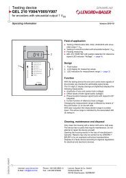
<strong>GEL</strong> <strong>244</strong><br />
Inkrementaler Zahnradgeber mit Sinus- oder<br />
Rechteck-Ausgangssignal<br />
Incremental Toothed-Wheel Encoder with Sine<br />
or Square Wave Output Signal<br />
Inhalt<br />
1. Sicherheitshinweise ............................3<br />
2. Beschreibung ......................................3<br />
3. Typenschlüssel ...................................5<br />
4. Handhabungshinweise........................5<br />
5. Elektrischer Anschluss........................8<br />
6. Justage .............................................10<br />
7. Technische Daten .............................11<br />
Betriebsanleitung<br />
Operating Instructions<br />
Contents<br />
1. Safety instructions ........................... 13<br />
2. Description ...................................... 13<br />
3. Type code........................................ 15<br />
4. Handling notes ................................ 15<br />
5. Electrical connection ....................... 18<br />
6. Adjustment ...................................... 20<br />
7. Technical data ................................. 21<br />
Irrtum und technische Änderungen Right to technical changes and<br />
vorbehalten errors reserved. 2003-03
Herausgeber / Published by:<br />
Lenord, Bauer & Co. GmbH<br />
Dohlenstrasse 32<br />
46145 Oberhausen • Germany<br />
Fon: +49 (0)208 9963-0 • Fax: +49 (0)208 676292<br />
Internet: http://www.lenord.de • E-Mail: info@lenord.de<br />
Doc. No. DS19-<strong>244</strong><br />
2 <strong>GEL</strong> <strong>244</strong>
1. Sicherheitshinweise<br />
Deutsch<br />
Obwohl der MiniCoder sehr robust ist, muss darauf geachtet werden, dass die Sensorelemente<br />
unterhalb der Sensorfläche nicht beschädigt werden. Der MiniCoder wird mit<br />
einer Schutzabdeckung für den Transport geliefert. Entfernen Sie diese erst kurz vor<br />
Einbau des Sensors. Wenn der MiniCoder zu Inspektions- oder Ausbesserungszwecken<br />
ausgebaut werden muss, Schutzabdeckung sofort wieder aufstecken.<br />
Der MiniCoder enthält Magnete. Bei der Annäherung an metallische Gegenstände ist<br />
deshalb darauf zu achten, dass sich diese und der Sensor nicht gegenseitig anziehen<br />
können: Eine Berührung mit dem Messzahnrad oder andere mechanische Stöße auf<br />
die Sensorfläche können die Sensorelemente beschädigen.<br />
Zur Herstellung eines ordnungsgemäßen Betriebszustands muss der MiniCoder<br />
präzise eingebaut und justiert werden. Deshalb sollen Einbau-, Anschluss- und<br />
Service-Arbeiten nur von qualifiziertem und geschultem Fachpersonal durchgeführt<br />
werden, unter Berücksichtigung der einschlägigen Unfallverhütungs- und Sicherheitsvorschriften<br />
sowie der Angaben in dieser Betriebsanleitung.<br />
Halten Sie die in der Produktdokumentation angegeben Grenzwerte unbedingt ein.<br />
Verwenden Sie den MiniCoder nur bestimmungsgemäß:<br />
Die MiniCoder <strong>GEL</strong> <strong>244</strong> sind ausschließlich für Messaufgaben im industriellen und<br />
gewerblichen Bereich bestimmt. Mit ihnen können Positionen, Längen, Winkel oder<br />
Drehzahlen gemessen werden.<br />
Sie gelten als Bestandteil einer Anlage und erfordern den Anschluss an eine spezielle<br />
Auswertelektronik wie sie ein Positioniercontroller oder ein elektronischer Zähler<br />
enthält.<br />
Eine andere oder darüber hinausgehende Verwendung gilt als nicht bestimmungsgemäß.<br />
Für hieraus entstehende Schäden haftet die Firma LENORD, BAUER & CO.<br />
GMBH nicht.<br />
Hinweis in eigener Sache<br />
Die Betriebsanleitung wurde mit größter Sorgfalt erstellt. Es kann jedoch keine Gewähr<br />
bezüglich Fehlerfreiheit übernommen werden.<br />
Die Betriebsanleitung ist bestimmt für den Betreiber bzw. Anlagenbauer sowie dessen<br />
Personal. Bitte bewahren Sie sie sorgfältig auf, so dass sie auch für einen möglichen<br />
späteren Serviceeinsatz am MiniCoder zur Verfügung steht.<br />
2. Beschreibung<br />
2.1 Einsatzbereich<br />
Der Einbaugeber <strong>GEL</strong> <strong>244</strong> ist eine platzsparende Lösung zur berührungslosen Messung<br />
von vorwiegend Rotationsbewegungen.<br />
Er kann für die Drehzahl- und Positionsmessung an Getrieben, Maschinen, Motoren und<br />
Hochgeschwindigkeitsspindeln eingesetzt werden.<br />
Ausgangssignale sind zwei um 90° phasenversetzte Signale zur Richtungserkennung,<br />
sinus- oder rechteckförmig, wahlweise mit Referenzimpuls. Die Ausgangsfrequenz der<br />
Signale reicht dabei von Stillstand (0 Hz) bis zu maximal 200 kHz.<br />
<strong>GEL</strong> <strong>244</strong> 3
Deutsch<br />
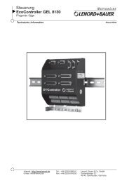
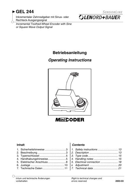
2.2 Funktionsprinzip<br />
Der <strong>GEL</strong> <strong>244</strong> tastet eine Maßverkörperung (Messzahnrad)<br />
aus ferromagnetischem Material ab. Das<br />
Magnetfeld des Einbaugebers wird durch die sich<br />
bewegende Maßverkörperung moduliert. Die Magnetfeldänderung<br />
wird vom Sensor erkannt und in<br />
ein sinus- oder rechteckförmiges Ausgangssignal<br />
umgesetzt.<br />
Der angegebene Maximalabstand und andere mechanische<br />
Einbautoleranzen sind unbedingt einzuhalten.<br />
Nur so kann die Funktion des Drehzahlsensors über dem gesamten Temperatur-<br />
und Frequenzbereich sichergestellt werden.<br />
Eine separate <strong>Elektronik</strong> (als Option von LENORD+BAUER lieferbar) sorgt für die Speisung<br />
des MiniCoders, die Auswertung der Impulszahlen und den Aufbau eines Regelkreises.<br />
Sinusförmige Messsignale (hier für Spur 1):<br />
3 V<br />
U ref =<br />
2,5 V<br />
u 1<br />
u 1<br />
elektrischer<br />
2 V<br />
Winkel<br />
0° 90° 180° 270° 360° 450° 540° 630° 720°<br />
Option<br />
u1(t) = UB/2 + û·sin(2·π·f·t)<br />
u–<br />
1(t) = UB/2 – û·sin(2·π·f·t)<br />
u2(t) = UB/2 û·cos(2·π·f·t)<br />
u–<br />
2(t) = UB/2 û·cos(2·π·f·t)<br />
(Vorzeichen je nach Drehrichtung)<br />
UB = 5 V; û = 250 mV<br />
4 <strong>GEL</strong> <strong>244</strong><br />
1<br />
1<br />
2<br />
2<br />
N<br />
N<br />
oder
3. Typenschlüssel<br />
Signalmuster (siehe auch Kapitel 5)<br />
<strong>GEL</strong> <strong>244</strong> XX 1 X X<br />
<br />
K– sinusförmige Spursignale<br />
KN sinusförmige Spursignale, analoger Referenzimpuls (von Nullfahne)<br />
KM sinusförmige Spursignale, analoger Referenzimpuls (von Nullnut)<br />
T– rechteckförmige Spursignale 5 V<br />
TN rechteckförmige Spursignale 5 V, digitaler Referenzimpuls 5 V<br />
Kabellänge<br />
G Standard 30 cm<br />
S Sonderkonfektionierung<br />
Modul m<br />
3 m = 0,3<br />
5 m = 0,5<br />
Ein Typenschlüssel der Form <strong>244</strong> Y … bezeichnet eine kundenspezifische Ausführung<br />
mit einer möglichen Spezialkonfektionierung oder Abweichung von den<br />
technischen Standardspezifikationen.<br />
4. Handhabungshinweise<br />
Deutsch<br />
Mechanische Schläge auf die Messseite oder sonstige Eingriffe können zum<br />
Totalausfall des Sensors führen!<br />
Bedingt durch den schmalen Luftspalt zwischen der Sensorfläche und der Maßverkörperung<br />
(Zahnrad) können Verunreinigungen im Bereich der Sensoroberfläche<br />
zu einer Zerstörung des MiniCoders führen oder das Messergebnis negativ<br />
beeinflussen. Falls solche betriebsmäßig auftreten können, bitte für entsprechende<br />
Säuberungsmechanismen sorgen (z. B. Fangmagnet für Eisenspäne).<br />
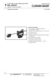
4.1 Zahnrad<br />
Passende Zahnräder können nach Kundenangaben bei LENORD+BAUER<br />
gefertigt werden. Bei eigener Anfertigung beachten Sie bitte folgende<br />
Punkte:<br />
• Es können Stahlzahnräder mit Evolventenverzahnung und Modul 0,3<br />
oder Modul 0,5 verwendet werden.<br />
• Mechanische Ungenauigkeiten in der Zahnperiode, der Zahnform<br />
und der Rundheit beeinträchtigen die Messgenauigkeit.<br />
• Eine angebrachte Referenzmarke (siehe nächsten Abschnitt) darf<br />
nicht über den Kopfkreis herausragen.<br />
• Weist das Zahnrad einen Höhenschlag auf, so muss der MiniCoder<br />
so justiert werden, dass die Luftspalttoleranz eingehalten wird (siehe<br />
Abschnitt 4.2).<br />
Benutzen Sie bitte das Zahnrad nur als Messrad und nicht zum Antrieb von anderen<br />
Komponenten; die Zähne dürfen nicht abnutzen!<br />
<strong>GEL</strong> <strong>244</strong> 5
Deutsch<br />
Referenzmarke<br />
0,5<br />
Fahne<br />
Nut<br />
4<br />
4.2 Montage<br />
Die Nullfahne muss aus ferromagnetischem Material bestehen. Sie<br />
darf nicht über den Kopfkreis herausragen!<br />
Bei höheren Drehzahlen entstehen große Zentrifugalkräfte. Es wird<br />
daher empfohlen, die Unwucht, die durch die Nullfahne hervorgerufen<br />
wird, durch Einbringen von Wuchtbohrungen in das Zahnrad bzw.<br />
durch Anbringen von Wuchtgewichten auszugleichen.<br />
Die Position der Nullfahne bzw. der Nullnut bestimmt die Phasenlage<br />
des Nullsignals bezüglich der Spursignale. Bei Einsatz der Interpolationselektronik<br />
<strong>GEL</strong> 214 von LENORD+BAUER muss sich die Nullfahne<br />
bzw. Nullnut mittig zwischen 2 Zähnen befinden. Werden andere<br />
Auswertelektroniken eingesetzt, sind die Spezifikationen des Herstellers<br />
unbedingt zu beachten.<br />
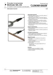
Wichtig: Zur Vermeidung von Beschädigungen achten Sie bitte<br />
darauf, dass die lediglich 0,1 mm starke Schutzschicht über<br />
dem Abtastsystem weder mit dem Zahnrad noch mit der Nullfahne<br />
oder irgendwelchen Werkzeugen in mechanischen<br />
Kontakt kommt. Die mitgelieferte Abstandslehre (siehe Bild,<br />
Stärke 0,1 mm für Modul 0,3 oder 0,15 mm für Modul 0,5)<br />
STOP<br />
haftet durch den eingebauten Magneten am MiniCoder und dient so auch als<br />
Transportschutz für die Messfläche.<br />
MiniCoder nur mit aufgesetzter Abstandslehre einbauen!<br />
Ohne Abstandslehre zieht der im MiniCoder eingebaute<br />
Permanentmagnet das Messsystem gegen das Zahnprofil mit<br />
der Folge einer möglichen Zerstörung des Messsystems.<br />
Mechanische Schläge auf die Messseite des MiniCoders<br />
oder ein Verkratzen der dünnen Schutzschicht führen zum<br />
Totalausfall des Systems.<br />
⇒ Notwendige Bohrungen im Sensor-Träger durchführen (siehe Bohr- und Fräsbild weiter<br />
unten)<br />
⇒ MiniCoder mit aufgesetzter Abstandslehre in die Anlage einsetzen<br />
⇒ MiniCoder symmetrisch zum Zahnrad ausrichten (beachten Sie bitte<br />
das Bohr- und Fräsbild weiter unten); Unsymmetrien führen zu Messfehlern!<br />
⇒ MiniCoder mit 2 Befestigungsschrauben M4 mit Unterlegscheibe und<br />
Federring leicht anschrauben<br />
⇒ Messabstand justieren (siehe 'Geberjustage' weiter unten)<br />
⇒ Schrauben mit einem Anzugsmoment von max. 60 Ncm festziehen<br />
Abstandslehre<br />
und Transportschutz<br />
⇒ Abstandslehre nach erfolgter Montage abziehen und für eine spätere Demontage oder<br />
Nachjustage des Gebers aufbewahren<br />
⇒ Kabel sicher verlegen und fixieren<br />
6 <strong>GEL</strong> <strong>244</strong>
Geberjustage (siehe auch Kapitel 6):<br />
Deutsch<br />
Der Abstand zwischen Mini-<br />
Coder-Messfläche und Zahnrad<br />
bzw. Nullfahne (Luftspalt d)<br />
muss sich innerhalb der festgelegten<br />
Toleranzen befinden<br />
(möglichen Höhenschlag des Zahnrades beachten).<br />
Beachten Sie in diesem Zusammenhang, dass bei großen<br />
Temperaturschwankungen und unterschiedlichen thermischen<br />
Ausdehnungskoeffizienten von Zahnrad und Trägerplatte des<br />
Gebers kritische Abstandsänderungen auftreten können.<br />
➤ Zu große Abstände wirken sich negativ auf die Messgenauigkeit aus (evtl. zu kleine<br />
Signalamplituden).<br />
➤ Zu kleine Abstände führen zu Übersteuerungen und damit zu möglichen Impulsverlusten.<br />
Maßbild:<br />
Modul<br />
Luftspalt d<br />
Einstellmaß<br />
Abstandstoleranz<br />
0,3 0,10 mm ± 0,02 mm<br />
0,5 0,15 mm ± 0,03 mm<br />
Maße in mm<br />
<strong>GEL</strong> <strong>244</strong> 7
Deutsch<br />
Bohr- und Fräsbild:<br />
4.3 Demontage des Gebers<br />
STOP<br />
M4<br />
A<br />
B<br />
A<br />
B<br />
27 0,1<br />
~<br />
8 <strong>GEL</strong> <strong>244</strong><br />
5 +1<br />
r a<br />
22 +1<br />
Drehachse<br />
4 H6 2 tief<br />
r a = d a/2 (d a = Kopfkreisdurchmesser des Zahnrads)<br />
Maße in mm<br />
MiniCoder nur mit aufgesetzter Abstandslehre ausbauen.<br />
Ohne Abstandslehre zieht der im MiniCoder eingebaute Permanentmagnet das<br />
Messsystem gegen das Zahnprofil mit der Folge einer möglichen Zerstörung<br />
des Messsystems.<br />
Mechanische Schläge auf die Messseite des MiniCoders oder ein Verkratzen<br />
der dünnen Schutzschicht führen zum Totalausfall des Systems.<br />
⇒ Abstandslehre zwischen MiniCoder und Messzahnrad einschieben<br />
⇒ M4 Befestigungsschrauben lösen<br />
⇒ MiniCoder ausbauen<br />
Mechanischen Kontakt der Messseite des MiniCoders mit dem Zahnprofil unbedingt<br />
vermeiden!<br />
5. Elektrischer Anschluss<br />
Je nach Typ des MiniCoders (siehe Typenschlüssel auf Seite 5) ergibt sich folgende<br />
Anschlussbelegung:<br />
Leitungs-<br />
Signal/Funktion<br />
farbe Spur K KM, KN T TN<br />
weiß 1<br />
braun /1<br />
rosa 2<br />
schwarz /2<br />
grau N<br />
gelb /N<br />
grün Sense<br />
rot U B = +5 V ± 5%<br />
blau 0 V (GND)<br />
Abschirmung auf der<br />
Geberseite nicht<br />
angeschlossen.
EGB-Hinweise (Elektrostatisch gefährdete Bauelemente)<br />
Wie bei jedem elektronischen Gerät sind auch beim Anschluss des Mini-<br />
Coders <strong>GEL</strong> <strong>244</strong> EGB-Vorsichtsmaßnahmen zu treffen. Grundsätzlich gilt,<br />
dass elektronische Baugruppen – insbesondere Steckerstifte<br />
und Anschlussdrähte – nur dann berührt werden sollen, wenn<br />
dies wegen daran vorzunehmender Arbeiten unvermeidbar ist. Der genaue<br />
Umfang der Schutzmaßnahmen richtet sich nach den örtlichen Gegebenheiten.<br />
Detaillierte Auskunft gibt die EN 100 015-1<br />
(CECC 00015-1).<br />
Im Allgemeinen ist eine leitfähige, fachkundig geerdete<br />
Arbeitsunterlage in Verbindung mit einem EGB-Armband<br />
ausreichend.<br />
Es ist erforderlich, die Schutzmaßnahmen in regelmäßigen<br />
Abständen auf ihre Wirksamkeit zu überprüfen.<br />
EMV-Hinweise (Elektromagnetische Verträglichkeit)<br />
Zur Verbesserung des elektromagnetischen Umfeldes (EMV) bitte folgende Einbauhinweise<br />
beachten:<br />
❏ Möglichst nur Stecker mit Metallgehäuse oder einem Gehäuse aus metallisiertem<br />
Kunststoff und abgeschirmte Kabel verwenden; den Schirm am Steckergehäuse<br />
auflegen<br />
❏ Schirme möglichst großflächig auflegen<br />
❏ Alle ungeschirmten Leitungen möglichst kurz halten<br />
❏ Erdungsverbindungen möglichst kurz und mit großem Querschnitt ausführen (z. B.<br />
induktionsarmes Masseband, Flachbandleiter)<br />
❏ Sollten zwischen den<br />
Maschinen- und <strong>Elektronik</strong>-Erdanschlüssen<br />
Potentialdifferenzen<br />
bestehen oder auftreten,<br />
so ist durch geeignete<br />
Maßnahmen dafür zu<br />
sorgen, dass über den<br />
Kabelschirm keine Ausgleichsströme<br />
fließen<br />
können; z. B. Potentialausgleichsleitung<br />
mit<br />
großem Querschnitt verlegen<br />
(siehe Grafik) oder<br />
Maschine<br />
Mini-<br />
Coder<br />
Potentialausgleichsleitung<br />
Interpolationselektronik<br />
(Option)<br />
Kabel mit getrennter 2fach-Schirmung verwenden, wobei die Schirme nur auf jeweils<br />
einer Seite aufgelegt werden<br />
Deutsch<br />
❏ Signal- und Steuerleitungen räumlich von den Leistungskabeln getrennt verlegen; ist<br />
dies nicht möglich, paarig verseilte und geschirmte Leitungen (twisted pair) verwenden<br />
und/oder die Geberleitung in einem Eisenrohr verlegen<br />
❏ Die Stromversorgung muss der Installationsart Klasse 0 gemäß Punkt B.3 der<br />
EN61000-4-5 von 1995 entsprechen<br />
<strong>GEL</strong> <strong>244</strong> 9<br />
<strong>GEL</strong><br />
212,<br />
213<br />
Nur bei ungünstigen<br />
Bedingungen wie:<br />
- sehr lange Kabel<br />
- extreme Störpegel<br />
<strong>GEL</strong><br />
214<br />
5 6 2<br />
Auswertelektronik<br />
Kontakt Gehäuse - Montageplatte<br />
über Zahnscheibe<br />
Steuerleitungen
Deutsch<br />
6. Justage<br />
• Luftspalt<br />
• Offset<br />
• Phase<br />
• Amplitudengleichlauf<br />
<strong>GEL</strong> <strong>244</strong><br />
<strong>GEL</strong> <strong>244</strong><br />
<strong>GEL</strong> <strong>244</strong><br />
<strong>GEL</strong> <strong>244</strong><br />
<strong>GEL</strong> <strong>244</strong><br />
<strong>GEL</strong> <strong>244</strong><br />
U 1+<br />
U 1-<br />
U 1+<br />
U 1-<br />
U 2+<br />
U 2-<br />
U 1+<br />
U 2+<br />
U 1+<br />
U 1-<br />
U 2+<br />
U 2-<br />
Messungen gelten für Typ <strong>GEL</strong> <strong>244</strong> Kx...<br />
AC 353 mV<br />
DC 60 mV<br />
DC 60 mV<br />
AC U1<br />
AC U2<br />
Amplitude Spur 1:<br />
290 … 400 mV (AC)<br />
Offset Spur 1:<br />
-60 … +60 mV (DC)<br />
Offset Spur 2:<br />
-60 … +60 mV (DC)<br />
Lissajousfigur:<br />
Idealer Kreis<br />
Amplitudenverhältnis:<br />
U1<br />
U2<br />
= 0,9 … 1,1<br />
Speziell für die oben beschriebenen Messungen wird von LENORD+BAUER ein Testgerät<br />
angeboten: <strong>GEL</strong> 210 K.<br />
10 <strong>GEL</strong> <strong>244</strong>
7. Technische Daten<br />
7.1 Elektrische Daten<br />
Versorgungsspannung UB<br />
Leistungsaufnahme ohne Last ≤ 1 W<br />
5 VDC ± 5%, verpolungsgeschützt<br />
Deutsch<br />
Ausgangssignale 2 um 90° phasenverschobene Sinus- oder<br />
Rechtecksignale (siehe Typenschlüssel) und<br />
deren inverse Signale, kurzschlussfest; optional<br />
mit Referenzsignal<br />
• Ein-/Ausgangsfrequenz<br />
• Pegel<br />
− Typ Kx<br />
− Typ Tx<br />
• Offset (statisch, Typ Kx)<br />
• Amplitudentoleranz (Typ Kx)<br />
• Amplitudengleichlauf (Typ Kx)<br />
0 ... 200 kHz (CL = 5 nF für Typ Kx)<br />
500 mVss (= 1 Vss als Differenzsignal)<br />
TTL-, RS422/485-kompatibel<br />
-60…+60 mV<br />
-20…+10%<br />
û1/û2 = 0,9…1,1<br />
Elektromagnetische Verträglichkeit Industrieanwendungen: EN 50081-1 und 2,<br />
EN 50082-1, EN 61000-6-2<br />
Anschluss 9 × 0,14 mm 2 , Schirm geberseitig nicht<br />
aufgelegt; vergossener Kabelabgang, 0,3 m<br />
(Standard); max. Kabellänge 100 m (Spannungsabfall<br />
an der Versorgungsleitung!)<br />
Isolationsfestigkeit 500 V<br />
6.2 Mechanische Daten<br />
Modul m 0,3; 0,5<br />
Messzahnradbreite ≥ 4 mm (Material: ferromagnetischer Stahl)<br />
zulässiger Luftspalt 0,10 ± 0,02 mm bei Modul 0,3<br />
0,15 ± 0,03 mm bei Modul 0,5<br />
Arbeitstemperaturbereich -30 °C ... +85 °C<br />
Betriebs- und Lagertemperaturbereich -40 °C ... +120 °C<br />
Schutzart IP 68<br />
Vibrationsfestigkeit (IEC 68-T2-6) 200 m/s 2<br />
Schockfestigkeit (IEC 68-T2-27) 2000 m/s 2<br />
Masse 30 g<br />
Gehäuse Kunststoff: Polyphenylensulfid (PPS), glasfaserverstärkt<br />
<strong>GEL</strong> <strong>244</strong> 11
Deutsch<br />
Notizen:<br />
12 <strong>GEL</strong> <strong>244</strong>
1. Safety instructions<br />
English<br />
Although the MiniCoder is of a robust design due care must be taken not to damage<br />
the sensor elements below the sensing face. The sensor is supplied with a protective<br />
cap for transport. Only remove this cap immediately prior to installation. Should the<br />
sensor be removed for inspection or repair the protective cap must be replaced<br />
immediately.<br />
The sensor contains magnets. Contact with the toothed measuring wheel or other<br />
mechanical impact on the sensing face can damage the sensor elements. Care should<br />
therefore be taken when holding the sensor near to metallic objects that they are not<br />
drawn together with force.<br />
In order to establish proper operating conditions the MiniCoder has to be mounted and<br />
adjusted precisely. Therefore, only skilled and trained personal should mount, connect<br />
and service the MiniCoder while following the current regulations for prevention of<br />
accidents and safety instructions as well as the operating instructions.<br />
Observe the limit values stated in the product documentation.<br />
The MiniCoder is only to be used as designated:<br />
The MiniCoders <strong>GEL</strong> <strong>244</strong> have been exclusively designed for performing measuring<br />
tasks in industry. They can be used to measure, for instance, positions, lengths,<br />
angles or speeds.<br />
They are considered to be components of a complete system and need to be connected<br />
to a special evaluation electronics which might be incorporated in a positioning<br />
controller or an electronic counter.<br />
Any use other than specified must be considered as non-designated and, consequently,<br />
LENORD, BAUER & CO. GMBH cannot be held responsible for any damage<br />
resulting from such use.<br />
Note<br />
These Operating Instructions have been produced with great care. However, no guarantees<br />
can be made for possible errors.<br />
The Operating Instructions are meant for use by the end-user or system integrator as well<br />
as their employees. Please keep this manual in a safe place for future use.<br />
2. Description<br />
2.1 Scope<br />
The <strong>GEL</strong> <strong>244</strong> MiniCoder is a space saving probe for non-contact measuring of rotational<br />
movements.<br />
It can be used for measuring speeds and positions in gear boxes, machines, transporters<br />
and high-speed spindles.<br />
Output signals available are two-track 90° phase-shifted signals for direction detection<br />
either sinusoidal or rectangular, optionally with reference pulse. The output frequency of<br />
the signals covers a range from 0 Hz (standstill) to 200 kHz at maximum.<br />
<strong>GEL</strong> <strong>244</strong> 13
English<br />
2.2 Functional principle<br />
The <strong>GEL</strong> <strong>244</strong> scans the target (toothed wheel) consisting<br />
of a ferromagnetic material. The magnetic<br />
field of the probe is modulated by the passing of the<br />
ferromagnetic toothed wheel. This modulation is<br />
evaluated in the sensor and converted to a sine or<br />
square wave output signal.<br />
or<br />
The given maximum distance and other mounting<br />
tolerances must be maintained. Otherwise, correct<br />
operating of the speed sensor over the whole temperature<br />
and frequency range cannot be guaranteed.<br />
A separate electronic circuit (optionally deliverable by LENORD+BAUER) has to provide the<br />
power supply for the MiniCoder, performs the evaluation of the measuring pulses and<br />
establishes the closed loop.<br />
Sinusoidal measuring signals (here for track 1):<br />
3 V<br />
U ref =<br />
2.5 V<br />
u 1<br />
u 1<br />
electric<br />
2 V<br />
angle<br />
0° 90° 180° 270° 360° 450° 540° 630° 720°<br />
Option<br />
u1(t) = UB/2 + û·sin(2·π·f·t)<br />
u–<br />
1(t) = UB/2 – û·sin(2·π·f·t)<br />
u2(t) = UB/2 û·cos(2·π·f·t)<br />
u–<br />
2(t) = UB/2 û·cos(2·π·f·t)<br />
(sign depends on sense of<br />
rotation)<br />
UB = 5 V; û = 250 mV<br />
14 <strong>GEL</strong> <strong>244</strong><br />
1<br />
1<br />
2<br />
2<br />
N<br />
N
3. Type code<br />
Signal pattern (see also chapter 5)<br />
<strong>GEL</strong> <strong>244</strong> XX 1 X X<br />
<br />
K– sinusoidal track signals<br />
KN sinusoidal track signals, analog reference pulse (by a flag)<br />
KM sinusoidal track signals, analog reference pulse (by a groove)<br />
T– square wave track signals 5 V<br />
TN square wave track signals 5 V, digital reference pulse 5 V<br />
Cable length<br />
G 30 cm (standard)<br />
S customized<br />
Module m<br />
3 m = 0.3<br />
5 m = 0.5<br />
Type code <strong>244</strong> Y … indicates a customer-specific version. Deviations from<br />
the type code above and/or the technical specifications are possible.<br />
4. Handling notes<br />
English<br />
Mechanical impacts and the like onto the measuring surface of the MiniCoder can<br />
permanently damage the probe!<br />
Because of the very small gap between the probe's front end surface and the<br />
target (toothed wheel) a build-up of metallic particles in this range may lead to the<br />
destruction of the MiniCoder or to measuring inaccuracies. In case that this<br />
situation may occur, please provide adequate cleaning mechanisms (e.g. a<br />
collection magnet for ferromagnetic chips).<br />
4.1 Toothed wheel<br />
LENORD+BAUER manufactures customised toothed wheels. If you use<br />
another toothed wheel please note the following:<br />
• Optimum measuring results will be achieved with involute tooth form<br />
and modules 0.3 or 0.5.<br />
• Mechanical inaccuracies concerning the tooth period, the tooth shape<br />
and the concentricity have a negative effect on the measuring<br />
accuracy.<br />
• A mounted reference mark (see next section) must not exceed the<br />
addendum circle of the toothed wheel.<br />
• If the toothed wheel shows an eccentricity the probe must be<br />
adjusted in such a way that the gap tolerance is maintained in case of<br />
the smallest distance to the toothed wheel (see section 4.2).<br />
Do not use the toothed wheel for driving any components but only for measuring<br />
purposes; the teeth must not wear out!<br />
<strong>GEL</strong> <strong>244</strong> 15
English<br />
Reference mark<br />
0.5<br />
Flag<br />
Groove<br />
4<br />
4.2 Mounting<br />
The reference mark must consist of ferromagnetic material. It must<br />
not exceed the addendum circle of the toothed wheel!<br />
Strong centrifugal forces will occur at higher rotational speeds. So<br />
we recommend to compensate the unbalance of the reference mark<br />
by balancing bores in the toothed wheel or by a balancing weight on<br />
the toothed wheel.<br />
The position of the reference flag/groove determines the phase position<br />
of the reference (zero) signal relative to the track signals. When<br />
using the <strong>GEL</strong> 214 Interpolation Electronics the reference flag/groove<br />
must be located exactly between two teeth. With other Interpolation<br />
Electronics the specifications of the manufacturer are to be observed.<br />
Important: Ensure that neither the toothed wheel nor the reference<br />
mark nor any tool mechanically contact the 0.1mmthin<br />
protective layer over the scanning system in order<br />
to avoid any damage. The distance gauge supplied with<br />
the MiniCoder (see picture, thickness 0.1 mm with<br />
module 0.3 or 0.15 mm with module 0.5) sticks to the<br />
MiniCoder by means of the incorporated magnet and, in<br />
STOP<br />
this way, serves to protect the sensitive measuring surface during transport<br />
and mounting.<br />
Only install the MiniCoder with the distance gauge<br />
attached!<br />
Without the distance gauge the permanent magnet in the<br />
MiniCoder will attract the measuring system to the tooth<br />
profile thus possibly causing the measuring system being<br />
damaged.<br />
Mechanical impacts onto the measuring surface of the<br />
MiniCoder will damage the system!<br />
distance gauge<br />
and transport<br />
protection<br />
⇒ Drill (and tap) the necessary holes into the sensor carrier plate (see the boring and<br />
milling scheme below)<br />
⇒ Insert the MiniCoder in the machine with the distance gauge attached<br />
⇒ Align the MiniCoder and the toothed wheel symmetrically (please note the boring and<br />
milling scheme below); dissymmetries will cause measuring errors!<br />
⇒ Fix the MiniCoder only lightly by means of two M4 screws with washer<br />
and lock washer<br />
⇒ Adjust the measuring distance as shown under 'Adjusting the probe'<br />
further below<br />
⇒ Tighten the screws with a maximum torque of 60 Ncm<br />
⇒ Remove the distance gauge after mounting the MiniCoder and keep it for future<br />
disassembly or readjustment<br />
⇒ Lay cables securely and fix them<br />
16 <strong>GEL</strong> <strong>244</strong>
Adjusting the probe (see also chapter 6):<br />
English<br />
The distance between the<br />
MiniCoder surface and the<br />
toothed wheel and reference<br />
mark (gap d) must not exceed<br />
the tolerances stated in the<br />
table (take into account a possible eccentricity of the toothed<br />
wheel).<br />
In this connection, please note that the gap may alter critically<br />
at large temperature fluctuations and different thermal<br />
expansion coefficients of the toothed wheel and the carrier<br />
plate.<br />
➤ If distance is too wide the measuring accuracy is affected negatively (signal amplitudes<br />
are possibly too small).<br />
➤ If distance is too small saturation might occur possibly leading to pulse losses.<br />
Dimensioned<br />
drawing:<br />
Module<br />
Gap d<br />
measure<br />
Tolerance<br />
0.3 0.10 mm ± 0.02 mm<br />
0.5 0.15 mm ± 0.03 mm<br />
measures<br />
in mm<br />
<strong>GEL</strong> <strong>244</strong> 17
English<br />
Boring and milling scheme:<br />
4.3 Removal of the probe<br />
STOP<br />
M4<br />
A<br />
B<br />
27 0,1<br />
18 <strong>GEL</strong> <strong>244</strong><br />
A<br />
B<br />
~<br />
5 +1<br />
r a<br />
22 +1<br />
Axis of rotation<br />
4 H6 2 deep<br />
r a = d a/2 (d a = OD of toothed wheel)<br />
measures in mm<br />
Only remove the MiniCoder with the distance gauge attached!<br />
Without the distance gauge the permanent magnet in the MiniCoder will attract<br />
the measuring system to the tooth profile thus possibly causing the measuring<br />
system being damaged.<br />
Mechanical impacts onto the measuring surface of the MiniCoder will<br />
damage the system!<br />
⇒ Insert the distance gauge between the MiniCoder and the measuring toothed wheel<br />
⇒ Loosen the two M4 screws<br />
⇒ Remove the MiniCoder<br />
Avoid any mechanical contact between the measuring system of the MiniCoder<br />
and the tooth profile!<br />
5. Electrical connection<br />
According to the type of MiniCoder (see Type code on page 15) the following pin layout is<br />
applicable:<br />
Line<br />
Signal/function<br />
color Track K KM, KN T TN<br />
white 1<br />
brown /1<br />
pink 2<br />
black /2<br />
grey N<br />
yellow /N<br />
green Sense<br />
red U B = +5 V ± 5%<br />
blue 0 V (GND)<br />
Screen is not wired<br />
in the probe.
English<br />
ESD protection (Electrostatic sensitive devices)<br />
For every electronic device, ESD protection is important. This also applies to<br />
the MiniCoders <strong>GEL</strong> <strong>244</strong>. Do not touch electronic devices unless servicing is<br />
required. This is particularly important for connector pins and<br />
loose wires. Which precautions are required in the particular<br />
case is dependant on to local situation. EN 100 015-1 (CECC 00015-1)<br />
gives a comprehensive overview on possible solutions.<br />
In most situations, a grounded working surface together<br />
with ESD wrist straps will give sufficient protection.<br />
We do recommend to check the ESD equipment<br />
regularly.<br />
EMC measures (Electromagnetic compatibility)<br />
To improve the electromagnetic environment please observe the following installation<br />
advice:<br />
❏ Only use connectors with metal housing or a housing made of metallized plastic and<br />
screened cables; make sure to set up a contact between the screening and the connector<br />
housing<br />
❏ The screenings must have large-surface contact<br />
❏ Keep all unscreened lines as short as possible<br />
❏ Provide for earth connections being as short as possible and having a large crosssection<br />
(e.g. low-inductance metal-alloy tape, flat-band conductor)<br />
❏ Should there be any<br />
potential difference<br />
between the earth connection<br />
of the machine<br />
and the electronics,<br />
appropriate measures<br />
must be taken to ensure<br />
that no compensating<br />
currents can flow through<br />
the cable screening (e.g.<br />
lay a potential equalisation<br />
line with large crosssection<br />
(see illustration)<br />
or use a cable with sepa-<br />
Machine<br />
Mini-<br />
Coder<br />
Potential<br />
equilization line<br />
Interpolation<br />
Electronics<br />
(optional)<br />
rated duplex screening – each screen being connected at one side only)<br />
❏ Signal and control lines must be laid away from electric power cables; if that is not<br />
possible use screened twisted pair cables and/or lay the encoder lines in iron pipes<br />
❏ The power supply must agree with installation class 0 according to point B.3 of the<br />
EN61000-4-5 from 1995<br />
<strong>GEL</strong> <strong>244</strong> 19<br />
<strong>GEL</strong><br />
212,<br />
213<br />
Under unfavourable<br />
conditions only, as<br />
- very long cables<br />
- extreme disturbance level<br />
<strong>GEL</strong><br />
214<br />
Electrical contact<br />
enclosure/mounting plate<br />
via tooth lock washer<br />
5 6 2<br />
Interpretation<br />
Electronics<br />
Control lines
English<br />
6. Adjustment<br />
• Gap<br />
• Offset<br />
• Phase<br />
• Amplitude ratio<br />
<strong>GEL</strong> <strong>244</strong><br />
<strong>GEL</strong> <strong>244</strong><br />
<strong>GEL</strong> <strong>244</strong><br />
<strong>GEL</strong> <strong>244</strong><br />
<strong>GEL</strong> <strong>244</strong><br />
<strong>GEL</strong> <strong>244</strong><br />
U 1+<br />
U 1-<br />
U 1+<br />
U 1-<br />
U 2+<br />
U 2-<br />
U 1+<br />
U 2+<br />
U 1+<br />
U 1-<br />
U 2+<br />
U 2-<br />
Measurements valid for type <strong>GEL</strong> <strong>244</strong> Kx...<br />
AC 353 mV<br />
DC 60 mV<br />
DC 60 mV<br />
AC U1<br />
AC U2<br />
Amplitude track 1:<br />
290 … 400 mV (AC)<br />
Offset track 1:<br />
-60 … +60 mV (DC)<br />
Offset track 2:<br />
-60 … +60 mV (DC)<br />
Lissajous figure:<br />
ideal circle<br />
Amplitude ratio:<br />
U1<br />
U2<br />
= 0.9 to 1.1<br />
Especially for realising the measurements shown above LENORD+BAUER offers you<br />
the test device <strong>GEL</strong> 210 K.<br />
20 <strong>GEL</strong> <strong>244</strong>
7. Technical data<br />
7.1 Electrical data<br />
Supply voltage UB<br />
Power consumption without load ≤ 1 W<br />
5 VDC ± 5%, reverse battery protected<br />
English<br />
Output signals two 90° phase-shifted sine- or square-wave signals<br />
(see Type coding) and their inverse signals, shortcircuit<br />
proof; optionally with reference pulse<br />
• Input/output frequency<br />
• Level<br />
− Kx type<br />
− Tx type<br />
• Offset (static, Kx type)<br />
• Amplitude tolerance (Kx type)<br />
• Amplitude ratio (Kx type)<br />
Electromagnetic compatibility<br />
(EMC)<br />
0 to 200 kHz (CL = 5 nF for Kx type)<br />
500 mVss (= 1 Vss difference signal)<br />
compatible with TTL and RS422/485<br />
-60 mV to +60 mV<br />
-20% to +10%<br />
ûA/ûB = 0.9 to 1.1<br />
industrial applications: EN 50081-1 and 2,<br />
EN 50082-1, EN 61000-6-2<br />
Connection 9 x 0.14 mm 2 , screen not connected on the probe<br />
side; sealed cable outlet, 0.3 m; max. cable length<br />
100 m (observe the voltage drop on the power<br />
line!)<br />
Insulation stability 500 V<br />
7.2 Mechanical data<br />
Module (m) 0.3, 0.5<br />
Width of the toothed wheel ≥ 4 mm (material: ferromagnetic steel)<br />
Admissible air gap 0.10 ± 0.02 mm with module 0.3<br />
0.15 ± 0.03 mm with module 0.5<br />
Operating temperature -30 °C to +85 °C<br />
Storage temperature -40 °C to +120 °C<br />
Protection class IP 68<br />
Vibration resistance (IEC 68-T2-6) 200 m/s 2<br />
Shock resistance (IEC 68-T2-27) 2000 m/s 2<br />
Weight 30 g<br />
Housing plastic: Polyphenylene sulfide (PPS), fibrereinforced<br />
<strong>GEL</strong> <strong>244</strong> 21