GEL 244 - ERTECH Elektronik AG
GEL 244 - ERTECH Elektronik AG
GEL 244 - ERTECH Elektronik AG

Erfolgreiche ePaper selbst erstellen
Machen Sie aus Ihren PDF Publikationen ein blätterbares Flipbook mit unserer einzigartigen Google optimierten e-Paper Software.
English<br />
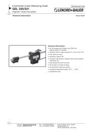
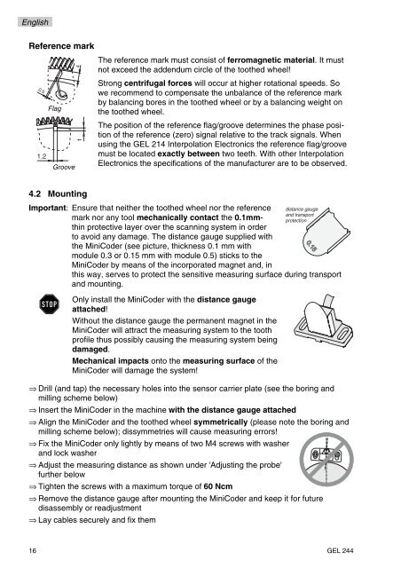
Reference mark<br />
0.5<br />
Flag<br />
Groove<br />
4<br />
4.2 Mounting<br />
The reference mark must consist of ferromagnetic material. It must<br />
not exceed the addendum circle of the toothed wheel!<br />
Strong centrifugal forces will occur at higher rotational speeds. So<br />
we recommend to compensate the unbalance of the reference mark<br />
by balancing bores in the toothed wheel or by a balancing weight on<br />
the toothed wheel.<br />
The position of the reference flag/groove determines the phase position<br />
of the reference (zero) signal relative to the track signals. When<br />
using the <strong>GEL</strong> 214 Interpolation Electronics the reference flag/groove<br />
must be located exactly between two teeth. With other Interpolation<br />
Electronics the specifications of the manufacturer are to be observed.<br />
Important: Ensure that neither the toothed wheel nor the reference<br />
mark nor any tool mechanically contact the 0.1mmthin<br />
protective layer over the scanning system in order<br />
to avoid any damage. The distance gauge supplied with<br />
the MiniCoder (see picture, thickness 0.1 mm with<br />
module 0.3 or 0.15 mm with module 0.5) sticks to the<br />
MiniCoder by means of the incorporated magnet and, in<br />
STOP<br />
this way, serves to protect the sensitive measuring surface during transport<br />
and mounting.<br />
Only install the MiniCoder with the distance gauge<br />
attached!<br />
Without the distance gauge the permanent magnet in the<br />
MiniCoder will attract the measuring system to the tooth<br />
profile thus possibly causing the measuring system being<br />
damaged.<br />
Mechanical impacts onto the measuring surface of the<br />
MiniCoder will damage the system!<br />
distance gauge<br />
and transport<br />
protection<br />
⇒ Drill (and tap) the necessary holes into the sensor carrier plate (see the boring and<br />
milling scheme below)<br />
⇒ Insert the MiniCoder in the machine with the distance gauge attached<br />
⇒ Align the MiniCoder and the toothed wheel symmetrically (please note the boring and<br />
milling scheme below); dissymmetries will cause measuring errors!<br />
⇒ Fix the MiniCoder only lightly by means of two M4 screws with washer<br />
and lock washer<br />
⇒ Adjust the measuring distance as shown under 'Adjusting the probe'<br />
further below<br />
⇒ Tighten the screws with a maximum torque of 60 Ncm<br />
⇒ Remove the distance gauge after mounting the MiniCoder and keep it for future<br />
disassembly or readjustment<br />
⇒ Lay cables securely and fix them<br />
16 <strong>GEL</strong> <strong>244</strong>