Montage- und Gebrauchsanleitung Universal Anschlagpunkt 115
Montage- und Gebrauchsanleitung Universal Anschlagpunkt 115
Montage- und Gebrauchsanleitung Universal Anschlagpunkt 115

Erfolgreiche ePaper selbst erstellen
Machen Sie aus Ihren PDF Publikationen ein blätterbares Flipbook mit unserer einzigartigen Google optimierten e-Paper Software.
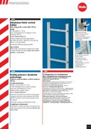
Hailo Wind Systems<br />
Hailo <strong>Universal</strong> <strong>Anschlagpunkt</strong> <strong>115</strong> EN 795:2012<br />
inkl. Befestigungssystem an ortsfester Steigleiter<br />
Hailo <strong>Universal</strong> Anchorage Point <strong>115</strong> EN 795:2012<br />
incl. system for securing to fixed vertical ladders<br />
<strong>Montage</strong>- <strong>und</strong> <strong>Gebrauchsanleitung</strong><br />
DE<br />
Instructions for fitting and use<br />
GB<br />
<strong>Montage</strong>- <strong>und</strong> <strong>Gebrauchsanleitung</strong> • <strong>Universal</strong> <strong>Anschlagpunkt</strong> • Revision 2013-11/DE/02
Hersteller:<br />
Hailo Wind Systems GmbH & Co. KG<br />
Daimlerstraße 2, 35708 Haiger, Germany<br />
+49 (0) 2773 82-0<br />
+49 (0) 2773 82-1561<br />
E-Mail: info@ hailo-windsystems.de<br />
www.hailo-windsystems.com<br />
© Hailo-Werk<br />
Ohne vorherige schriftliche Genehmigung durch Hailo<br />
darf kein Teil dieser Publikation in irgendeiner Weise<br />
vervielfältigt, übertragen, umgeschrieben, in einem<br />
Speichermedium gespeichert oder in eine andere Sprache<br />
oder Computersprache übersetzt werden. Verstöße gegen<br />
das Urheberrecht können zudem die Produktunterstützung<br />
durch Hailo für dieses Gerät beeinträchtigen.<br />
Hailo behält sich das Recht vor, ohne vorherige Ankündigung<br />
Änderungen an diesem Handbuch <strong>und</strong> am darin<br />
beschriebenen Produkt vorzunehmen. Der Inhalt dieses<br />
Handbuchs beinhaltet keine vertraglichen oder andere<br />
Verpflichtungen seitens Hailo <strong>und</strong> ist auch nicht rechtlich<br />
bindend.<br />
Diese <strong>Montage</strong>- <strong>und</strong> <strong>Gebrauchsanleitung</strong> ist vor<br />
der <strong>Montage</strong> bzw. vor der Benutzung des <strong>Universal</strong><br />
<strong>Anschlagpunkt</strong>es sorgfältig zu lesen <strong>und</strong> zur Kenntnis<br />
zu nehmen.<br />
Der Betreiber muss sicherstellen, dass diese <strong>Montage</strong><strong>und</strong><br />
<strong>Gebrauchsanleitung</strong> bei jedem Steigleitersystem<br />
vor Ort (oder an einer geeigneten Stelle) aufbewahrt<br />
wird <strong>und</strong> bei Bedarf dem Benutzer jederzeit zur<br />
Verfügung gestellt werden kann.<br />
Diese Publikation wurde mit größter Sorgfalt erstellt.<br />
Falls Sie jedoch Fehler feststellen oder Vorschläge zur<br />
Verbesserung unterbreiten möchten, schreiben Sie bitte<br />
an Hailo. Dieses Handbuch liegt im Original in deutscher<br />
Sprache vor. Falls gewünscht, können Sie schriftlich eine<br />
Kopie anfordern.<br />
2<br />
<strong>Montage</strong>- <strong>und</strong> <strong>Gebrauchsanleitung</strong> • <strong>Universal</strong> <strong>Anschlagpunkt</strong> • Revision 2013-11/DE/02
Inhaltsverzeichnis:<br />
1. Bestimmungsgemäße Verwendung . . . . . .<br />
2. Sicherheitshinweise . . . . . . . . . . . . . . . .<br />
3. Produktbeschreibung . . . . . . . . . . . . . . .<br />
4. Kennzeichnung . . . . . . . . . . . . . . . . . . .<br />
5. <strong>Montage</strong> des<br />
<strong>Universal</strong> <strong>Anschlagpunkt</strong>es . . . . . . . . . . .<br />
5.1 Allgemeine <strong>Montage</strong>hinweise . . . . . . . . .<br />
5.2 <strong>Montage</strong> an Bauwerk . . . . . . . . . . . . . . .<br />
4<br />
4<br />
6<br />
7<br />
8<br />
8<br />
9<br />
DE<br />
Sollte der <strong>Universal</strong> <strong>Anschlagpunkt</strong> in ein anderes<br />
Land weiterverkauft werden, ist es zur Sicherheit des<br />
Benutzers erforderlich, dass ihm diese <strong>Montage</strong>- <strong>und</strong><br />
<strong>Gebrauchsanleitung</strong> in der jeweiligen Landessprache<br />
zur Verfügung steht.<br />
Diese <strong>Montage</strong>- <strong>und</strong> <strong>Gebrauchsanleitung</strong> ist auch in der<br />
jeweils aktuellen Amtssprache des Bestimmungslandes<br />
erhältlich.<br />
Nähere Informationen dazu erhalten Sie unter<br />
info@ hailo-windsystems.de<br />
oder wenden Sie sich an:<br />
Hailo Wind Systems GmbH & Co. KG<br />
Daimlerstraße 2, 35708 Haiger, Germany<br />
5.3 <strong>Montage</strong> an ortsfester Steigleiter . . . . . . .<br />
5.4 <strong>Montage</strong> an ortsfester Steigleiter<br />
mit Steigschutzschiene . . . . . . . . . . . . . .<br />
5.5 <strong>Montage</strong> an ortsfester Steigleiter<br />
mit SKYLOTEC Steigschutzschiene . . . . . .<br />
6. Technische Daten . . . . . . . . . . . . . . . . . .<br />
7. Pfl ege, Wartung, Inspektion . . . . . . . . . .<br />
8. Rettungsmaßnahmen . . . . . . . . . . . . . . .<br />
9. Prüfung . . . . . . . . . . . . . . . . . . . . . . . .<br />
10<br />
12<br />
14<br />
16<br />
16<br />
17<br />
18<br />
<strong>Montage</strong>- <strong>und</strong> <strong>Gebrauchsanleitung</strong> • <strong>Universal</strong> <strong>Anschlagpunkt</strong> • Revision 2013-11/DE/02<br />
3
1. Bestimmungsgemäße Verwendung<br />
2. Sicherheitshinweise<br />
Der <strong>Universal</strong> <strong>Anschlagpunkt</strong> dient als Absturzsicherung<br />
von Personen.<br />
Dabei sichert sich der Benutzer mit einem Verbindungsmittel<br />
am <strong>Universal</strong> <strong>Anschlagpunkt</strong>. Der Karabinerhaken<br />
des Verbindungsmittels wird am <strong>Anschlagpunkt</strong> eingehakt!<br />
Der <strong>Universal</strong> <strong>Anschlagpunkt</strong> darf nur in<br />
Verbindung mit einer Persönlichen Schutzausrüstung<br />
gegen Absturz verwendet werden.<br />
Es ist verboten am <strong>Universal</strong> <strong>Anschlagpunkt</strong><br />
Hebevorrichtungen oder andere Gegenstände zu<br />
befestigen.<br />
Dieser <strong>Anschlagpunkt</strong> darf von max. 2 Personen<br />
gleichzeitig verwendet werden.<br />
• Der <strong>Universal</strong> <strong>Anschlagpunkt</strong> ist so anzubringen, dass er<br />
leicht <strong>und</strong> ohne Behinderung zum An- <strong>und</strong> Aushängen<br />
des Anschlagmittels erreicht werden kann.<br />
• Der <strong>Anschlagpunkt</strong> ist so anzubringen, dass keine<br />
Gefahrenstellen (Quetschstellen, Scherstellen, Fangoder<br />
Stoßstellen) entstehen, die den Benutzer gefährden<br />
oder den Transport durch Hervorstehen behindern.<br />
• Der Anbringungsort ist so zu wählen, dass die eingeleiteten<br />
Kräfte vom Gr<strong>und</strong>werkstoff aufgenommen werden<br />
können. Es darf dabei keine Verformung auftreten, die<br />
die Sicherheit beeinträchtigen kann.<br />
• Die Lage der <strong>Anschlagpunkt</strong>e an der Last ist so zu<br />
wählen, dass unzulässige Beanspruchungen, z.B. durch<br />
außermittigen Lastangriff, vermieden werden.<br />
• Der <strong>Anschlagpunkt</strong> ist so anzubringen, dass eine mögliche<br />
Beschädigung der Persönlichen Schutzausrüstung gegen<br />
Absturz (PSA) durch Konstruktionsteile, z.B. scharfe<br />
Kanten, ausgeschlossen ist.<br />
• <strong>Anschlagpunkt</strong>e sind nach den <strong>Montage</strong>arbeiten sowie<br />
mindestens einmal jährlich durch einen Sachk<strong>und</strong>igen<br />
zu prüfen. Der Anwender hat die Ergebnisse der Gefährdungsbeurteilung<br />
nach Betriebssicherheitsverordnung zu<br />
beachten.<br />
• <strong>Anschlagpunkt</strong>e sind regelmäßig vor dem Gebrauch,<br />
z.B. durch den Anschläger, durch Sichtkontrolle zu überprüfen<br />
(Schraubensitz, Korrosion, Anrisse der Schweißnaht,<br />
Verformung).<br />
Werden Unregelmäßigkeiten festgestellt, darf der<br />
<strong>Anschlagpunkt</strong> nicht benutzt werden.<br />
4<br />
<strong>Montage</strong>- <strong>und</strong> <strong>Gebrauchsanleitung</strong> • <strong>Universal</strong> <strong>Anschlagpunkt</strong> • Revision 2013-11/DE/02
• Der <strong>Universal</strong> <strong>Anschlagpunkt</strong> darf ausschließlich für das<br />
Anschlagen Persönlicher Schutzausrüstungen (PSA)<br />
gegen Absturz verwendet werden.<br />
Bestandteile der Persönlichen Schutzausrüstung<br />
gegen Absturz:<br />
Verbindungsmittel gem. EN 354<br />
Falldämpfer gem. EN 355<br />
Verbindungselemente (Karabinerhaken) gem. EN 362<br />
Auffanggurte nach EN 361 sind ausschließlich zur<br />
Benutzung des <strong>Anschlagpunkt</strong>es zulässig.<br />
• Der <strong>Universal</strong> <strong>Anschlagpunkt</strong> muss leicht erkennbar sein.<br />
• Der <strong>Universal</strong> <strong>Anschlagpunkt</strong> darf nicht mit aggressiven<br />
Chemikalien, Säuren oder deren Dämpfen in Verbindung<br />
gebracht werden.<br />
• Der <strong>Universal</strong> <strong>Anschlagpunkt</strong> darf nur durch beauftragte<br />
<strong>und</strong> unterwiesene Personen verwendet werden.<br />
• Bestehen Zweifel an einer sicheren Benutzung oder ist<br />
der <strong>Anschlagpunkt</strong> durch einen Absturz beansprucht<br />
worden, so muss er aus Sicherheitsgründen der<br />
Benutzung entzogen werden.<br />
Eine weitere Benutzung muss durch einen Sachk<strong>und</strong>igen<br />
ermittelt werden.<br />
• Der Benutzer des Steigleitersystems muss körperlich<br />
<strong>und</strong> mental in der Lage sein, die jeweilige Anlage sicher<br />
zu begehen.<br />
Sollte im Vorfeld die Einnahme von Medikamenten<br />
erforderlich gewesen sein, so ist es ratsam, sich über<br />
etwaige Nebenwirkungen, die bei der Benutzung des<br />
Systems zu einer Beeinträchtigung oder zu körperlichen<br />
Schäden führen können, zu informieren.<br />
• Der Benutzer des Steigleitersystems hat sich vor<br />
Arbeitsbeginn bei dem Betreiber über einen Notfallplan<br />
mit eventuell erforderlichen Rettungsmaßnahmen,<br />
deren Einleitung <strong>und</strong> Umsetzung zu informieren.<br />
• <strong>Anschlagpunkt</strong>e <strong>und</strong> Anschlageinrichtungen, die innerhalb<br />
eines Steigsystems zur Anwendung kommen, sind<br />
in ihrer Lage so zu wählen, dass der freie Fall <strong>und</strong> die<br />
Absturzhöhe auf ein Mindestmaß beschränkt werden.<br />
• Vor jeder Benutzung ist der erforderliche Freiraum am<br />
Arbeitsplatz unterhalb des Benutzers sicherzustellen,<br />
so dass im Falle eines Absturzes kein Aufprall auf dem<br />
Boden oder einem Hindernis möglich ist.<br />
Warnung:<br />
Anschlageinrichtungen die falsch montiert, beschädigt<br />
oder unsachgemäß verwendet werden, können bei<br />
einem Absturz zu schweren oder tödlichen Verletzungen<br />
führen.<br />
Vor Gebrauch <strong>Anschlagpunkt</strong> kontrollieren!<br />
DE<br />
<strong>Montage</strong>- <strong>und</strong> <strong>Gebrauchsanleitung</strong> • <strong>Universal</strong> <strong>Anschlagpunkt</strong> • Revision 2013-11/DE/02<br />
5
3. Produktbeschreibung<br />
• Der permanente <strong>Anschlagpunkt</strong> wird zur Höhensicherung<br />
verwendet.<br />
• Dieser <strong>Anschlagpunkt</strong> darf von max. 2 Personen<br />
gleichzeitig verwendet werden.<br />
• Durch die große Öse des <strong>Anschlagpunkt</strong>es ist eine<br />
Absicherung mit jedem Verbindungsmittel möglich.<br />
• Das CE-Zertifi zierungsverfahren ist auf diesen Anschlag<br />
punkt nicht anwendbar, da es sich nicht um eine PSA<br />
(Persönliche Schutzausrüstung) im Sinne der Richtlinie<br />
89/686/EWG handelt.<br />
• Der <strong>Universal</strong> <strong>Anschlagpunkt</strong> ist nach den<br />
Anforderungen folgender Normen geprüft:<br />
EN 795:2012<br />
CEN/TS 16415:2012<br />
OSHA 1910.66<br />
OSHA 1926.502<br />
ANSI Z359.1-2007<br />
Der <strong>Universal</strong> <strong>Anschlagpunkt</strong> für max. 2 Personen<br />
ist für eine Lastaufnahme von 22,24 kN ausgelegt.<br />
Vor der <strong>Montage</strong> des <strong>Anschlagpunkt</strong>esr ist sicherzustellen,<br />
dass die Kraftüberleitung zum tragenden<br />
Bauwerk hin, mit ausreichender Sicherheit gewährleistet<br />
ist.<br />
Gegebenenfalls muss die <strong>Montage</strong> mit dem Tragwerksplaner<br />
oder einem Statiker abgestimmt werden!<br />
Vor jeder Benutzung ist sicherzustellen, dass sich der<br />
<strong>Anschlagpunkt</strong> in sichtbar einwandfreiem Zustand<br />
befi ndet <strong>und</strong> keine Riefen, Stoßspuren oder Verformungen<br />
aufweist.<br />
Werden Unregelmäßigkeiten festgestellt, darf der<br />
<strong>Anschlagpunkt</strong> nicht benutzt werden. Eine eventuelle<br />
Benutzung muss durch einen Sachk<strong>und</strong>igen geprüft<br />
werden.<br />
6<br />
<strong>Montage</strong>- <strong>und</strong> <strong>Gebrauchsanleitung</strong> • <strong>Universal</strong> <strong>Anschlagpunkt</strong> • Revision 2013-11/DE/02
4. Kennzeichnung<br />
Typenschild A: <strong>Universal</strong> <strong>Anschlagpunkt</strong> Onshore, Art.-Nr. 6034481, Korrosivitätskategorie C4, Lang<br />
DE<br />
Typenschild B: <strong>Universal</strong> <strong>Anschlagpunkt</strong> Offshore, Art.-Nr. 6034501, Korrosivitätskategorie C5-M, Lang<br />
Kennzeichnung am Bauwerk<br />
Typ: <strong>Universal</strong>-<strong>Anschlagpunkt</strong> <strong>115</strong><br />
Type: <strong>Universal</strong> anchorage point <strong>115</strong><br />
Hersteller / Supplier: Hailo Wind Systems GmbH & Co. KG<br />
Nominale Tragfähigkeit / Nominal WLL: 22,24 kN<br />
Personenzahl / Persons: max. 2<br />
<strong>Montage</strong> mit 2 Schrauben / Mounting with 2 srews<br />
M 16 - 8.8 Festigkeit / Consistency<br />
Anzugsmoment / Torque: 210 Nm<br />
Geprüft nach Anforderung / Specifications required:<br />
EN 795:2012, CEN/TS 16415:2012,<br />
OSHA 1910.66, OSHA 1926.502,<br />
ANSI Z359.1-2007<br />
1173449 · 11/13<br />
<strong>Montage</strong>- <strong>und</strong> <strong>Gebrauchsanleitung</strong> • <strong>Universal</strong> <strong>Anschlagpunkt</strong> • Revision 2013-11/DE/02<br />
7
5. <strong>Montage</strong> des <strong>Universal</strong> <strong>Anschlagpunkt</strong>es<br />
5.1 Allgemeine <strong>Montage</strong>hinweise<br />
Zugelassene Belastungsrichtungen<br />
Der <strong>Universal</strong> <strong>Anschlagpunkt</strong> darf nur in vorgegebener<br />
Richtung belastet werden.<br />
Die <strong>Montage</strong>richtung ist so zu wählen, dass der<br />
<strong>Universal</strong> <strong>Anschlagpunkt</strong> nur in zugelassener<br />
Belastungsrichtung wirken kann.<br />
Verboten ist<br />
Achtung!<br />
Bei nicht ordnungsgemäßer Handhabung<br />
(Zusammenbau, <strong>Montage</strong>, Beschädigung der Oberfläche<br />
etc.) erlöscht die Betriebserlaubniss <strong>und</strong><br />
jegliche Gewährleistung des Herstellers.<br />
• eine Änderung jeglicher Art am <strong>Anschlagpunkt</strong>,<br />
insbesondere Bohren oder Schleifen,<br />
• die Benutzung eines <strong>Anschlagpunkt</strong>es, der sichtbar nicht<br />
in einwandfreiem Zustand ist oder von dem angenommen<br />
wird, dass er einen Absturz aufgefangen hat,<br />
• die Benutzung des <strong>Anschlagpunkt</strong>es zu einem anderen<br />
Zweck als zum Schutz einer Person gegen Absturz aus<br />
der Höhe.<br />
8<br />
<strong>Montage</strong>- <strong>und</strong> <strong>Gebrauchsanleitung</strong> • <strong>Universal</strong> <strong>Anschlagpunkt</strong> • Revision 2013-11/DE/02
5.2 <strong>Montage</strong> an Bauwerk<br />
<strong>Montage</strong> an Mauerwerken:<br />
• Für Mauerwerke dürfen nur bauaufsichtlich zugelassene<br />
Dübel verwendet werden.<br />
• Bei nicht definierten Untergründen ist das Befestigungssystem<br />
in Abstimmung mit dem Tragwerksplaner auszuführen.<br />
• Eine Durchgangsverankerung mit Gegenplatte ist auch<br />
denkbar. Dies ist mit dem Bauwerksplaner abzustimmen<br />
<strong>und</strong> nachzuweisen.<br />
<strong>Montage</strong> an Betonbauwerken:<br />
• Für Betonbauwerke dürfen nur bauaufsichtlich<br />
zugelassene Dübel verwendet werden.<br />
• Bei nicht definierten Untergründen ist das Befestigungssystem<br />
in Abstimmung mit dem Tragwerksplaner auszuführen.<br />
• Betonqualität = C 20 - 25<br />
• Dübelauszugskraft = ≥ 12 kN<br />
Empfehlung: Befestigungsdübel HILTI HST-R M16<br />
Anzugsmomente des Befestigungsdübels beachten!<br />
<strong>Montage</strong> an Stahlbauwerken:<br />
• <strong>Montage</strong> des <strong>Anschlagpunkt</strong>es an vorhandene Butzen.<br />
Die Befestigung erfolgt mit Schrauben (M16,<br />
Festigkeit 8.8).<br />
• Die Schrauben müssen mit einem Anzugsmoment von<br />
210 Nm angezogen werden.<br />
• Als Schraubensicherung sind Sicherungsmuttern<br />
nach DIN 985 oder DIN 980 zugelassen.<br />
Alternativ ist ein flüssiges Schraubensicherungsmittel<br />
wie z.B. Loctite zu verwenden.<br />
• Es ist in jedem Fall darauf zu achten, dass der<br />
<strong>Anschlagpunkt</strong> ordnungsgemäß montiert wurde <strong>und</strong><br />
die Befestigung am Bauwerk / Untergr<strong>und</strong> den<br />
Vorgaben entspricht.<br />
DE<br />
<strong>Montage</strong>- <strong>und</strong> <strong>Gebrauchsanleitung</strong> • <strong>Universal</strong> <strong>Anschlagpunkt</strong> • Revision 2013-11/DE/02<br />
9
5. <strong>Montage</strong> des <strong>Universal</strong> <strong>Anschlagpunkt</strong>es<br />
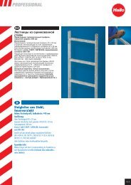
5.3 <strong>Montage</strong> an ortsfester Steigleiter<br />
Achtung! Bei nicht ordnungsgemäßer Handhabung<br />
(Zusammenbau, <strong>Montage</strong>, Beschädigung der Oberfläche<br />
etc.) erlöscht die Betriebserlaubniss <strong>und</strong> jegliche<br />
Gewährleistung des Herstellers.<br />
Der <strong>Universal</strong> <strong>Anschlagpunkt</strong> ist für die Installation<br />
an einer Aluminium Steigleiter von Hailo<br />
Typ ALO 72 MA/BA zugelassen.<br />
Bei einer <strong>Montage</strong> auf Leitern anderer Hersteller muss<br />
der Planer die geforderte Standsicherheit nachweisen,<br />
um die auftretenden Kräfte sicher abzuleiten.<br />
Die Leiter muss nach den Anforderung der<br />
EN ISO 14122-4 ausgelegt <strong>und</strong> montiert sein.<br />
Die Positionierung der Aufnahmeplatte an der Leiter ist<br />
variabel. Die <strong>Montage</strong> kann sowohl mittig als auch seitlich<br />
erfolgen. Die vorgeschriebenen Auftrittsbreiten müssen<br />
dabei eingehalten werden.<br />
Befestigung seitlich:<br />
X = min. 300 mm<br />
Befestigung mittig:<br />
X = min. 150 mm<br />
Die <strong>Montage</strong> des <strong>Universal</strong> <strong>Anschlagpunkt</strong>es<br />
erfolgt mit verschiedenen Befestigungselementen<br />
an 5 Leitersprossen.<br />
1) 3 Leitersprossen werden zunächst mit einem Sprossenreparatur-Set<br />
[1] verstärkt.<br />
Jeweils ein Rohr [1a] in die Leitersposse schieben <strong>und</strong><br />
beidseitig mit Anschraublasche [1c] <strong>und</strong> Senkkopfschraube<br />
M16x50 [1b] befestigen.<br />
Anzugsmoment der Schrauben: 80 Nm<br />
2) U-Profi l [2] von hinten an der 1. <strong>und</strong> 5. Leitersprosse<br />
mit dem Bügelschrauben-Set [5] befestigen.<br />
Anzugsmoment: 20 Nm<br />
3) Aufnahmeplatte [3] von vorne an den mittleren<br />
3 Leitersprossen mit dem Bügelschrauben-Set [5]<br />
befestigen.<br />
Anzugsmoment: 20 Nm<br />
4) <strong>Anschlagpunkt</strong> [4] an die Aufnahmeplatte montieren<br />
(Schrauben M16x50, DIN 933, Festigkeit 8.8 [6] ).<br />
Anzugsmoment: 210 Nm<br />
Bei den jährlichen Prüfungen des <strong>Anschlagpunkt</strong>es<br />
ist der feste Sitz der Schraubverbindungen zu prüfen!<br />
10<br />
<strong>Montage</strong>- <strong>und</strong> <strong>Gebrauchsanleitung</strong> • <strong>Universal</strong> <strong>Anschlagpunkt</strong> • Revision 2013-11/DE/02
DE<br />
<strong>Montage</strong>- <strong>und</strong> <strong>Gebrauchsanleitung</strong> • <strong>Universal</strong> <strong>Anschlagpunkt</strong> • Revision 2013-11/DE/02<br />
11
5. <strong>Montage</strong> des <strong>Universal</strong> <strong>Anschlagpunkt</strong>es<br />
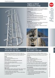
5.4 <strong>Montage</strong> an ortsfester Steigleiter mit Hailo oder Haca Steigschutzschiene<br />
Achtung! Bei nicht ordnungsgemäßer Handhabung<br />
(Zusammenbau, <strong>Montage</strong>, Beschädigung der Oberfläche<br />
etc.) erlöscht die Betriebserlaubniss <strong>und</strong> jegliche<br />
Gewährleistung des Herstellers.<br />
Die Befestigungskomponenten des <strong>Universal</strong><br />
<strong>Anschlagpunkt</strong>es erlauben eine <strong>Montage</strong> auf<br />
ortsfester Steigleiter mit Steigschutzschienen unterschiedlicher<br />
Hersteller.<br />
Die Aufnahmeplatte wird mit zusätzlichen Befestigungskomponenten<br />
mit der Steigschutzschiene an der<br />
Leitersprosse befestigt.<br />
Befi ndet sich an einer Stelle, an der die Aufnahmeplatte<br />
montiert werden soll, bereits eine Steigschutzschienen-Befestigung,<br />
muss diese entfernt <strong>und</strong><br />
– nach Vorgabe der <strong>Montage</strong>schritte 1-4 – ersetzt<br />
werden.<br />
<strong>Montage</strong>beispiel:<br />
Die <strong>Montage</strong> des <strong>Universal</strong> <strong>Anschlagpunkt</strong>es erfolgt<br />
mit verschiedenen Befestigungselementen, zusammen<br />
mit der Steigschutzschiene, an 3 Leitersprossen.<br />
1) 3 Leitersprossen werden zunächst mit einem Sprossenreparatur-Set<br />
[1] verstärkt.<br />
Jeweils ein Rohr [1a] in die Leitersposse schieben <strong>und</strong><br />
beidseitig mit Anschraublasche [1c] <strong>und</strong> Senkkopfschraube<br />
M16x50 [1b] befestigen.<br />
Anzugsmoment der Schrauben: 80 Nm<br />
2) Aufnahmeplatte [2] von hinten an diese 3 Leitersprossen<br />
positionieren. Zusammen mit der Steigschutzschiene<br />
wird die Aufnahmeplatte mit 3 Befestigungssets [4]<br />
an die Leitersprossen montiert.<br />
Anzugsmoment: 20 Nm<br />
3) <strong>Anschlagpunkt</strong> [3] an die Aufnahmeplatte montieren<br />
(Schrauben M16x50, DIN 933, Festigkeit 8.8 [5] ).<br />
Anzugsmoment: 210 Nm<br />
4) Zusätzlich wird die Steigschutzschiene an der nächsten<br />
Leitersprosse ober- <strong>und</strong> unterhalb der Aufnahmeplatte<br />
mit einem Befestigungsset [4] fi xiert.<br />
Die vorgeschriebenen<br />
Auftrittsbreiten müssen<br />
eingehalten werden:<br />
X = min. 150 mm<br />
Bei den jährlichen Prüfungen des <strong>Anschlagpunkt</strong>es<br />
ist der feste Sitz der Schraubverbindung zu prüfen!<br />
12<br />
<strong>Montage</strong>- <strong>und</strong> <strong>Gebrauchsanleitung</strong> • <strong>Universal</strong> <strong>Anschlagpunkt</strong> • Revision 2013-11/DE/02
DE<br />
<strong>Montage</strong>- <strong>und</strong> <strong>Gebrauchsanleitung</strong> • <strong>Universal</strong> <strong>Anschlagpunkt</strong> • Revision 2013-11/DE/02<br />
13
5. <strong>Montage</strong> des <strong>Universal</strong> <strong>Anschlagpunkt</strong>es<br />
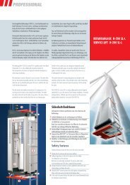
5.5 <strong>Montage</strong> an ortsfester Steigleiter mit SKYLOTEC-Steigschutzschiene<br />
Achtung! Bei nicht ordnungsgemäßer Handhabung<br />
(Zusammenbau, <strong>Montage</strong>, Beschädigung der Oberfläche<br />
etc.) erlöscht die Betriebserlaubniss <strong>und</strong> jegliche<br />
Gewährleistung des Herstellers.<br />
Die Befestigungskomponenten des <strong>Universal</strong><br />
<strong>Anschlagpunkt</strong>es erlauben eine <strong>Montage</strong> auf<br />
ortsfester Steigleiter mit Steigschutzschienen unterschiedlicher<br />
Hersteller.<br />
Die Aufnahmeplatte wird mit zusätzlichen Befestigungskomponenten<br />
mit der Steigschutzschiene an der<br />
Leitersprosse befestigt.<br />
Befi ndet sich an einer Stelle, an der die Aufnahmeplatte<br />
montiert werden soll, bereits eine Steigschutzschienen-Befestigung,<br />
muss diese entfernt <strong>und</strong><br />
– nach Vorgabe der <strong>Montage</strong>schritte 1-3 – ersetzt<br />
werden.<br />
Die <strong>Montage</strong> des <strong>Universal</strong> <strong>Anschlagpunkt</strong>es erfolgt<br />
zusammen mit der SKYLOTEC-Steigschutzschiene an<br />
3 Leitersprossen.<br />
1) 3 Leitersprossen werden zunächst mit einem Sprossenreparatur-Set<br />
[1] verstärkt.<br />
Jeweils ein Rohr [1a] in die Leitersposse schieben <strong>und</strong><br />
beidseitig mit Anschraublasche [1c] <strong>und</strong> Senkkopfschraube<br />
M16x50 [1b] befestigen.<br />
Anzugsmoment der Schrauben: 80 Nm<br />
2) Aufnahmeplatte [2] von hinten an diese 3 Leitersprossen<br />
positionieren. Zusammen mit der SKYLOTEC-<br />
Steigschutzschiene wird die Aufnahmeplatte mit jeweils<br />
2 Befestigungssets [4] an die 3 Leitersprossen montiert.<br />
Anzugsmoment: 85 Nm<br />
3) <strong>Anschlagpunkt</strong> [3] an die Aufnahmeplatte montieren<br />
(Schrauben M16x50, DIN 933, Festigkeit 8.8 [5] ).<br />
Anzugsmoment: 210 Nm<br />
Zusätzlich wird die SKYLOTEC-Steigschutzschiene an<br />
der nächsten Leitersprosse ober- <strong>und</strong> unterhalb der<br />
Aufnahmeplatte mit einem zusätzlichen Befestigungsset<br />
fi xiert.<br />
Die vorgeschriebenen<br />
Auftrittsbreiten müssen<br />
eingehalten werden:<br />
Bei den jährlichen Prüfungen des <strong>Anschlagpunkt</strong>es<br />
ist der feste Sitz der Schraubenverbindung zu prüfen!<br />
X = min. 150 mm<br />
14<br />
<strong>Montage</strong>- <strong>und</strong> <strong>Gebrauchsanleitung</strong> • <strong>Universal</strong> <strong>Anschlagpunkt</strong> • Revision 2013-11/DE/02
DE<br />
<strong>Montage</strong>- <strong>und</strong> <strong>Gebrauchsanleitung</strong> • <strong>Universal</strong> <strong>Anschlagpunkt</strong> • Revision 2013-11/DE/02<br />
15
6. Technische Daten 7. Pflege, Wartung, Inspektion<br />
Hersteller:<br />
Hailo Wind Systems GmbH & Co. KG<br />
Daimlerstraße 2, 35708 Haiger, Germany<br />
+49 (0) 2773 82-0<br />
+49 (0) 2773 82-1561<br />
E-Mail: info@ hailo-windsystems.de<br />
www.hailo-windsystems.com<br />
Leistungsdaten <strong>Universal</strong> <strong>Anschlagpunkt</strong><br />
Nominale Tragfähigkeit<br />
Abmessungen <strong>Universal</strong> <strong>Anschlagpunkt</strong>:<br />
22,24 kN<br />
Personenzahl max. 2<br />
Befestigungsschrauben M16 - 8.8<br />
Anzugsmoment M 16 - 8.8<br />
Dübelauszugskraft<br />
Anzugsmoment Dübel<br />
210 Nm<br />
≥ 12 kN<br />
siehe Angaben des<br />
jeweiligen Herstellers<br />
• Bei Verschmutzung reinigen Sie den <strong>Universal</strong> <strong>Anschlagpunkt</strong><br />
mit sauberem Wasser <strong>und</strong> entfernen die Restfeuchte<br />
mit einem trockenen Lappen.<br />
• Stellen Sie sicher, dass der <strong>Universal</strong> <strong>Anschlagpunkt</strong><br />
nicht mit Säuren oder anderen Flüssigkeiten in<br />
Berührung kommt.<br />
• Vor jeder Benutzung des <strong>Universal</strong> <strong>Anschlagpunkt</strong>es<br />
muss eine visuelle <strong>und</strong> manuelle Inspektion durch den<br />
Anwender ausgeführt werden.<br />
• Überprüfen Sie die korrekte Befestigung aller Komponenten,<br />
es dürfen keinerlei Verformungen, Schäden,<br />
Risse oder andere Fehler feststellbar sein.<br />
• Es ist bekannt, dass Geräte zeit- <strong>und</strong> nutzungsabhängig<br />
verschleißen. Es ist schwierig, die genaue Lebensdauer<br />
zu bestimmen, da dies von der Nutzungsintensität <strong>und</strong><br />
Frequenz sowie der Einsatzumgebung abhängig ist.<br />
Um die Sicherheit des <strong>Universal</strong> <strong>Anschlagpunkt</strong>es zu<br />
garantieren, muss die Installation sowie alle<br />
Komponenten in Zeitabständen die sich nach ihrer<br />
Beanspruchung richten, mindestens 1x jährlich überprüft<br />
werden. Diese Inspektion muss durch eine<br />
sachk<strong>und</strong>ige / befähigte Person ausgeführt werden,<br />
wobei der Prüfplan in dieser <strong>Montage</strong> <strong>und</strong> Gebrauchsanweisung<br />
benutzt werden sollte.<br />
Die Überprüfung ist auch nach Schadensfällen <strong>und</strong><br />
außergewöhnlichen Ereignissen notwendig.<br />
16<br />
<strong>Montage</strong>- <strong>und</strong> <strong>Gebrauchsanleitung</strong> • <strong>Universal</strong> <strong>Anschlagpunkt</strong> • Revision 2013-11/DE/02
8. Rettungsmaßnahmen<br />
Der Unternehmer oder Betreiber einer Anlage hat einen<br />
Plan bereitzustellen, in dem alle, bei der Benutzung des<br />
Steigschutzsystems möglichen Notfälle, Berücksichtigung<br />
fi nden.<br />
Verbindliche Regeln sind in der folgenden<br />
Broschüre nachzulesen:<br />
BGR 199 = Benutzung von<br />
persönlichen Schutzausrüstungen zum<br />
Retten aus Höhen <strong>und</strong> Tiefen<br />
Hinweis für Erste Hilfe Maßnahmen<br />
Im Falle eines Absturzes <strong>und</strong> dadurch bedingtem längeren,<br />
bewegungslosen Hängen im Auffanggurt (> 15 Minuten)<br />
können erhebliche Ges<strong>und</strong>heitsgefahren auftreten.<br />
Es besteht dabei die Gefahr eines Hängetraumas (orthostatischer<br />
Schock).<br />
Auch wenn keine äußeren Anzeichen auf eine Verletzung<br />
schließen lassen, sollte die gerettete Person in eine Kauerstellung<br />
gebracht werden, siehe Bild [A].<br />
Durch plötzliche Flachlagerung besteht akute Lebensgefahr<br />
durch Herzüberlastung <strong>und</strong> Nierenversagen.<br />
[A]<br />
DE<br />
Nur zur Rettung aus Höhen <strong>und</strong> Tiefen dürfen zusätzlich<br />
Notabstiegsgeräte eingesetzt werden<br />
(siehe BGR 199, Kap. 3.1.3.6 Anschlageinrichtungen).<br />
Eine unverzügliche ärztliche Untersuchung <strong>und</strong> Versorgung<br />
des Verletzten zur Beurteilung des Ges<strong>und</strong>heitszustandes<br />
ist in jedem Fall erforderlich.<br />
Benachrichtigung des Arztes über NOTRUF!<br />
<strong>Montage</strong>- <strong>und</strong> <strong>Gebrauchsanleitung</strong> • <strong>Universal</strong> <strong>Anschlagpunkt</strong> • Revision 2013-11/DE/02<br />
17
9. Prüfung<br />
Prüfkriterien Prüfplan Ergebnis:<br />
Beachten <strong>und</strong> kontrollieren Sie die<br />
folgenden Punkte<br />
vor jeder Inbetriebnahme,<br />
in regelmäßigen Abständen,<br />
nach der <strong>Montage</strong> <strong>und</strong><br />
nach außergewöhnlichen Ereignissen.<br />
Nur vollständig überprüfte Produkte<br />
unterliegen nach der Gewährleistungsdauer<br />
noch der Produkthaftpflicht des<br />
Herstellers.<br />
Füllen Sie den Prüfplan sorgfältig aus <strong>und</strong><br />
bewahren Sie ihn auf, um regelmäßige<br />
Prüfungen <strong>und</strong> evtl. Instandsetzungen<br />
darin zu dokumentieren.<br />
1. Festen Schraubensitz überprüfen. Bei Verwendung flüssiger<br />
Schraubensicherungsmittel, Schrauben nicht nachziehen<br />
2. Vollständigkeit der PSA - Anschlageinrichtung<br />
3. Verformung an tragenden Teilen wie Gr<strong>und</strong>körper <strong>und</strong> Schrauben<br />
4. Starke Korrosion<br />
5. Anrisse an tragenden Teilen<br />
6. Lesbarkeit der Produktkennzeichnung am <strong>Anschlagpunkt</strong><br />
7. Mechanische Beschädigung wie starke Kerben,<br />
insbesondere in auf Zugspannung belastete Bereiche<br />
Geprüft am:<br />
Nächster / Spätester Prüftermin<br />
Sachverständiger / Techniker / Prüfer<br />
Typenbezeichnung<br />
Bemerkungen<br />
Gr<strong>und</strong> der Bearbeitung (Festgestellte Schäden, Instandsetzung)<br />
Serien Nr.<br />
<strong>Montage</strong>datum<br />
Die Seite kann als Kopiervorlage für<br />
weitere Prüfungen verwendet werden!<br />
18<br />
<strong>Montage</strong>- <strong>und</strong> <strong>Gebrauchsanleitung</strong> • <strong>Universal</strong> <strong>Anschlagpunkt</strong> • Revision 2013-11/DE/02
1. Prüfung<br />
in Ordnung<br />
nicht<br />
in Ordnung<br />
2. Prüfung 3. Prüfung 4. Prüfung<br />
in Ordnung<br />
nicht<br />
in Ordnung<br />
in Ordnung<br />
nicht<br />
in Ordnung<br />
in Ordnung<br />
nicht<br />
in Ordnung<br />
DE<br />
Die durchgeführte Prüfung wurde nach den vom Hersteller vorgegebenen Unterweisungen, sowie den Regeln für den Einsatz<br />
von persönlichen Schutzrüstungen gegen Absturz BGR 198 <strong>und</strong> den entsprechenden Vorschriften der UVV durchgeführt.<br />
Dies wird mit einer Unterschrift bestätigt.<br />
<strong>Montage</strong>- <strong>und</strong> <strong>Gebrauchsanleitung</strong> • <strong>Universal</strong> <strong>Anschlagpunkt</strong> • Revision 2013-11/DE/02<br />
19
Notizen<br />
20<br />
<strong>Montage</strong>- <strong>und</strong> <strong>Gebrauchsanleitung</strong> • <strong>Universal</strong> <strong>Anschlagpunkt</strong> • Revision 2013-11/DE/02
Notes<br />
Instructions for fitting and use • <strong>Universal</strong> anchorage point • Revised 2013-11/GB/02<br />
21
Manufacturer:<br />
Hailo Wind Systems GmbH & Co. KG<br />
Daimlerstraße 2, 35708 Haiger, Germany<br />
+49 (0) 2773 82-0<br />
+49 (0) 2773 82-1561<br />
E-Mail: info@ hailo-windsystems.de<br />
Website: www.hailo-windsystems.com<br />
© Hailo-Werk<br />
No part of this publication may be copied, transmitted,<br />
transcribed, saved to a storage medium or translated into<br />
another language or computer language in any way<br />
whatsoever without prior written authorisation from Hailo.<br />
Any breach of copyright might also compromise the product<br />
support provided by Hailo for this device.<br />
Hailo reserves the right to make changes to this manual<br />
and to the product described in it without prior notice. The<br />
content of this manual does not constitute any contractual<br />
or other obligation on the part of Hailo nor is it legally<br />
binding.<br />
These instructions for fi tting and use must be read<br />
carefully and the contents noted before the<br />
universal anchorage point is fi tted or used.<br />
The operator must ensure that these instructions for<br />
fi tting and use are kept to hand at the site of all<br />
vertical ladder systems (or in a suitable location)<br />
and if required make them available to users at all<br />
times.<br />
We have taken the greatest care in preparing this publication.<br />
If, however, you come across any errors or if you have<br />
any suggestions for improvement, please contact Hailo at<br />
the above address.<br />
The original text of this manual is available in German.<br />
If you would like a copy, please submit your request in<br />
writing.<br />
22<br />
Instructions for fitting and use • <strong>Universal</strong> anchorage point • Revised 2013-11/GB/02
Table of contents:<br />
1. Approved use of the<br />
anchorage point . . . . . . . . . . . . . . . . .<br />
24<br />
2. Safety instructions . . . . . . . . . . . . . . . .<br />
24<br />
3. Product description . . . . . . . . . . . . . . .<br />
26<br />
4. Markings . . . . . . . . . . . . . . . . . . . . . .<br />
27<br />
5. Fitting the universal<br />
anchorage point . . . . . . . . . . . . . . . . .<br />
28<br />
5.1 General fitting instructions . . . . . . . . . .<br />
28<br />
If the universal anchorage point is resold to another<br />
country, it is essential for the safety of the end-user<br />
that this manual is received in the local language.<br />
5.2 Fitting to the structure . . . . . . . . . . . . .<br />
5.3 Fitting to a fixed vertical ladder . . . . . .<br />
5.4 Fitting to a fixed vertical ladder<br />
with a fall protection rail . . . . . . . . . . .<br />
29<br />
30<br />
32<br />
GB<br />
This manual is also available in the current<br />
offi cial language of the destination country.<br />
For more information, please contact<br />
info@ hailo-windsystems.de<br />
5.5 Fitting to a fixed vertical ladder<br />
with a SKYLOTEC fall protection rail . . .<br />
6. Technical data . . . . . . . . . . . . . . . . . . .<br />
7. Care, maintenance, inspection . . . . . . .<br />
34<br />
36<br />
36<br />
or contact:<br />
Hailo Wind Systems GmbH & Co. KG<br />
Daimlerstraße 2, 35708 Haiger, Germany<br />
8. Rescue measures . . . . . . . . . . . . . . . . .<br />
9. Inspection . . . . . . . . . . . . . . . . . . . . . .<br />
37<br />
38<br />
Instructions for fitting and use • <strong>Universal</strong> anchorage point • Revised 2013-11/GB/02<br />
23
1. Approved use of the anchorage point 2. Safety instructions<br />
The universal anchorage point serves as fall protection<br />
for persons.<br />
This requires the user to secure themselves to the<br />
universal anchorage point using a means of attachment.<br />
The karabiner clip on the means of attachment is<br />
clipped onto the anchorage point.<br />
The universal anchorage point may only be used with<br />
Personal Protective Equipment (PPE) for<br />
preventing falls.<br />
It is forbidden to attach lifting devices or other<br />
objects to the universal anchorage point.<br />
This anchorage point may be used by no more<br />
than 2 persons at the same time.<br />
• The universal anchorage point is to be fitted so that it<br />
can be accessed easily and without obstruction when<br />
attaching and removing the means of attachment.<br />
• The anchorage point is to be fitted so that no potential<br />
hazards are created (e.g. so there is no possibility of<br />
the device being crushed, shearing off, becoming<br />
trapped or exposed to impact) which would endanger<br />
the user or impede travel by protruding.<br />
• The anchorage point is to be fitted where the forces<br />
generated in the event of a fall can be withstood by the<br />
base material. Ensure that there is no risk of distortion<br />
that might compromise safety.<br />
• It is essential to position the anchorage points on the<br />
load to prevent excessive stress, e.g. as a result of<br />
applying the load off-centre.<br />
• The anchorage point is to be fitted so as to eliminate<br />
the possibility of damage to the Personal Protective<br />
Equipment against fall from a height (PPE) that might<br />
be caused by parts of the structure, e.g. sharp edges.<br />
• Anchorage points are to be inspected by trained<br />
personnel once the fitting work has been completed<br />
and at least once a year thereafter. The user must<br />
comply with the outcome of the risk assessment in<br />
accordance with German occupational health and safety<br />
legislation [Betriebssicherheitsverordnung].<br />
• Anchorage points are to be inspected regularly before<br />
use, e.g. a visual check is to be carried out by the user<br />
(for tightness of the bolts, corrosion, cracks in the welding<br />
and distortion).<br />
If any irregularities are identified, the anchorage point<br />
must not be used.<br />
24<br />
Instructions for fitting and use • <strong>Universal</strong> anchorage point • Revised 2013-11/GB/02
• The universal anchorage point is to be used solely for<br />
attaching personal protective equipment (PPE) in order<br />
to protect against falls.<br />
Components of personal protective equipment (PPE)<br />
against falls:<br />
Lanyards according to EN 354<br />
Energy absorbers according to EN 355<br />
Connectors (karabiner clip) according to EN 362<br />
Only safety harnesses which comply with EN 361 are<br />
allowed when using the universal anchorage point.<br />
• The universal anchorage point must be easily visible.<br />
• The universal anchorage point must not come into<br />
contact with aggressive chemicals, acids or acid vapours.<br />
• The universal anchorage point may only be used by<br />
authorised and trained personnel.<br />
• If there is any doubt as to whether it can be used safely<br />
or if the anchorage point has been subjected to stress<br />
due to a fall, it must be taken out of service for safety<br />
reasons.<br />
Trained personnel then need to investigate whether it is<br />
safe to be used again.<br />
• The user of the vertical ladder system must be physically<br />
and mentally capable of safely accessing the respective<br />
equipment.<br />
If the user has been required to take medication prior<br />
to using the equipment, it is advisable to fi nd out about<br />
possible side-effects which might result in impairment or<br />
physical injury when using the system.<br />
• Prior to starting work, the user of the vertical ladder<br />
system must ask the plant operator for details of the<br />
emergency plan as well as any rescue measures that<br />
might be necessary and how to initiate and execute<br />
them.<br />
• Anchorage points and stop devices used in a climbing<br />
system are to be positioned so that free falling and<br />
the fall height are restricted to a minimum.<br />
• Before each use, the necessary clear space in the working<br />
area below the user must be ensured, so that in<br />
the event of a fall no impact with the floor or other<br />
obstacle is possible.<br />
IMPORTANT:<br />
Anchorage points which are incorrectly fi tted,<br />
damaged or subject to improper use may result in<br />
serious or fatal injury in the event of fall.<br />
Check the anchorage point before use.<br />
GB<br />
Instructions for fitting and use • <strong>Universal</strong> anchorage point • Revised 2013-11/GB/02<br />
25
3. Product description<br />
• The fi xed anchorage point is used for working safely<br />
at heights.<br />
• This anchorage point may be used by no more than 2<br />
persons at the same time.<br />
• Users are secured to the large eyelet on the anchorage<br />
point using any means of attachment.<br />
• The CE certifi cation process does not apply to this<br />
anchorage point as it does not constitute an item of<br />
PPE (personal protective equipment) for the purposes of<br />
Directive 89/686/EEC.<br />
• The universal anchorage point is tested to meet the<br />
requirements of the following standards:<br />
EN 795:2012<br />
CEN/TS 16415:2012<br />
OSHA 1910.66<br />
OSHA 1926.502<br />
ANSI Z359.1-2007<br />
The universal anchorage point for up to 2 persons<br />
is designed to take a load of 22.24 kN.<br />
Before fi tting the anchorage point, ensure that the<br />
transfer of forces to the load-bearing structure is<br />
guaranteed with adequate safety.<br />
It might be necessary to obtain the approval of the<br />
designer of the supporting structure or a structural<br />
engineer for the fi tting of the anchorage point.<br />
Each time before it is used, ensure that the<br />
anchorage point is in a visibly so<strong>und</strong> condition<br />
and that there are no striations, evidence of<br />
impact or distortion.<br />
If any irregularities are identifi ed, the anchorage<br />
point must not be used.<br />
Trained personnel then need to investigate<br />
whether it is safe to be used again.<br />
26<br />
Instructions for fitting and use • <strong>Universal</strong> anchorage point • Revised 2013-11/GB/02
4. Markings<br />
Type plate A: <strong>Universal</strong> anchorage point Onshore, item no. 6034481, Corrosivity Category C4: high<br />
Type plate B: <strong>Universal</strong> anchorage point Offshore, item no. 6034501, Corrosivity Category C5-M: high<br />
GB<br />
Markings on the structure<br />
Typ: <strong>Universal</strong>-<strong>Anschlagpunkt</strong> <strong>115</strong><br />
Type: <strong>Universal</strong> anchorage point <strong>115</strong><br />
Hersteller / Supplier: Hailo Wind Systems GmbH & Co. KG<br />
Nominale Tragfähigkeit / Nominal WLL: 22,24 kN<br />
Personenzahl / Persons: max. 2<br />
<strong>Montage</strong> mit 2 Schrauben / Mounting with 2 srews<br />
M 16 - 8.8 Festigkeit / Consistency<br />
Anzugsmoment / Torque: 210 Nm<br />
Geprüft nach Anforderung / Specifications required:<br />
EN 795:2012, CEN/TS 16415:2012,<br />
OSHA 1910.66, OSHA 1926.502,<br />
ANSI Z359.1-2007<br />
1173449 · 11/13<br />
Instructions for fitting and use • <strong>Universal</strong> anchorage point • Revised 2013-11/GB/02<br />
27
5. Fitting the universal anchorage point<br />
5.1 General fitting instructions<br />
Permitted load directions<br />
The universal anchorage point may only be<br />
weighted with a load in the prescribed direction.<br />
Select the direction of mounting so that the<br />
universal anchorage point can only act in the<br />
permitted load direction<br />
It is forbidden to:<br />
IMPORTANT:<br />
The operating licence will be revoked and all<br />
warranties on the part of manufacturer<br />
invalidated if this device is not handled in<br />
accordance with these instructions (i.e. improper<br />
assembly or fitting, surface damage, etc.).<br />
• modify the anchorage point in any way, especially by<br />
drilling or grinding<br />
• use an anchorage point which is not in a visibly so<strong>und</strong><br />
condition or where it appears to have absorbed the<br />
impact of a fall<br />
• use the anchorage point for a different purpose to<br />
protecting the user from falls from heights<br />
28<br />
Instructions for fitting and use • <strong>Universal</strong> anchorage point • Revised 2013-11/GB/02
5.2 Fitting to the structure<br />
Fitting to masonry:<br />
• Only dowels permitted <strong>und</strong>er building regulations<br />
requirements may be used for masonry.<br />
• Where the base material cannot be identified, a system<br />
for affixing the ladder system is to be agreed with the<br />
designer of the supporting structure.<br />
• It is also possible to anchor the system through the<br />
masonry using a counter plate. This is to be discussed<br />
and verified with the structural engineer.<br />
Fitting to concrete structures:<br />
• Only dowels permitted <strong>und</strong>er building regulations<br />
requirements may be used for concrete structures.<br />
• Where the base material cannot be identified, a system<br />
for affixing the ladder system is to be agreed with the<br />
designer of the supporting structure.<br />
• Concrete category = C 20 - 25<br />
• Dowel pull-out strength = ≥ 12 kN<br />
Recommended dowel for fixing to concrete structures:<br />
HILTI HST-R M16<br />
Ensure that the torques for the dowels used for<br />
affixing the ladder are observed.<br />
Fitting to steel structures:<br />
• Fitting the anchor point to existing lugs.<br />
The anchorage point is secured using bolts<br />
(M16, property class 8.8).<br />
• The bolts must be tightened with a torque<br />
of 210 Nm.<br />
• DIN 985 or DIN 980-compliant lock nuts are<br />
approved for securing the bolts.<br />
Alternatively, a liquid threadlocker, such as Loctite,<br />
can be used.<br />
• In all cases, ensure that the anchor point has been<br />
fitted as specified and that it is secured to the<br />
structure/gro<strong>und</strong> according to the specifications.<br />
GB<br />
Instructions for fitting and use • <strong>Universal</strong> anchorage point • Revised 2013-11/GB/02<br />
29
5. Fitting the universal anchorage point<br />
5.3 Fitting to a fixed vertical ladder<br />
IMPORTANT: The operating licence will be<br />
revoked and all warranties on the part of manufacturer<br />
invalidated if this device is not handled in<br />
accordance with these instructions (i.e. improper<br />
assembly or fitting, surface damage, etc.).<br />
The universal anchorage point is approved for fi tting to<br />
Hailo aluminium vertical ladders, type ALO 72 MA/BA.<br />
When fi tting to ladders supplied by other manufacturers,<br />
the designer must verify that the required stability<br />
is available for absorbing the forces generated in<br />
the event of a fall. The ladder must be designed and<br />
installed to meet EN ISO 14122-4 requirements.<br />
The universal anchorage point is fi tted to 5 ladder<br />
rungs with various fi xtures.<br />
1) 3 ladder rungs are fi rst reinforced using a rung<br />
repair kit [1].<br />
Push a tube [1a] into each rung and secure it on both<br />
sides with an adjusting screw [1c] and countersunk<br />
screw M16x50 [1b].<br />
Torque to be applied to screws: 80 Nm<br />
2) Secure the U profi le [2] to the 1st and 5th rungs of the<br />
ladder from behind using the U bolt set [5].<br />
Torque: 20 Nm<br />
3) Secure the location plate [3] to the 3 middle rungs<br />
from the front using the U bolt set [5].<br />
Torque: 20 Nm<br />
4) Fit the anchorage point [4] to the location plate<br />
(M16x50 bolts, DIN 933, property class 8.8 [6]).<br />
Torque: 210 Nm<br />
The position of the location plate on the ladder can be varied.<br />
The anchorage point can be fi tted in the centre or on the side of<br />
the ladder. Ensure that the specifi ed tread widths are observed.<br />
Attached on the side:<br />
X = min. 300 mm<br />
Attached in the centre:<br />
X = min. 150 mm<br />
When carrying out the annual inspection of the<br />
anchorage point, the bolts and screws must be<br />
checked to ensure that they are screwed tight.<br />
30<br />
Instructions for fitting and use • <strong>Universal</strong> anchorage point • Revised 2013-11/GB/02
GB<br />
Instructions for fitting and use • <strong>Universal</strong> anchorage point • Revised 2013-11/GB/02<br />
31
5. Fitting the universal anchorage point<br />
5.4 Fitting to a fixed vertical ladder with a Hailo or Haca fall protection rail<br />
IMPORTANT: The operating licence will be<br />
revoked and all warranties on the part of manufacturer<br />
invalidated if this device is not handled in<br />
accordance with these instructions (i.e. improper<br />
assembly or fitting, surface damage, etc.).<br />
The components supplied for fi tting the universal<br />
anchorage point allow it to be fi tted to a fi xed<br />
vertical ladder with fall protection rails of different<br />
manufacturers.<br />
The location plate is secured to the rung using<br />
additional components with the fall protection rail.<br />
If a fall protection rail fi xture is already in place<br />
where the location plate needs to be fi tted, the<br />
existing fi xture must be removed and replaced<br />
according to the assembly steps 1-4.<br />
Installation example:<br />
The universal anchorage point is fi tted to 3 ladder<br />
rungs using various fi xtures together with the<br />
fall protection rail.<br />
1) 3 ladder rungs are fi rst reinforced using a<br />
rung repair kit [1].<br />
Push a tube [1a] into each rung and secure it on both<br />
sides with an adjusting screw [1c] and countersunk<br />
screw M16x50 [1b].<br />
Torque to be applied to screws: 80 Nm<br />
2) Position the location plate [2] on these 3 rungs<br />
from behind. Together with the fall protection rail,<br />
the location plate is secured to the rungs using<br />
3 mounting sets [4].<br />
Torque: 20 Nm<br />
3) Fit the anchorage point [3] to the location plate<br />
(M16x50 bolts, DIN 933, property class 8.8 [5]).<br />
Torque: 210 Nm<br />
4) In addition to this, the fall protection rail is secured to<br />
the next rung above and the next rung below the<br />
location plate using a mounting set [4].<br />
Ensure that the specifi ed<br />
tread widths are observed.<br />
X = min. 150 mm<br />
When carrying out the annual inspection of the<br />
anchorage point, the bolts and screws must be<br />
checked to ensure that they are screwed tight.<br />
32<br />
Instructions for fitting and use • <strong>Universal</strong> anchorage point • Revised 2013-11/GB/02
GB<br />
Instructions for fitting and use • <strong>Universal</strong> anchorage point • Revised 2013-11/GB/02<br />
33
5. Fitting the universal anchorage point<br />
5.5 Fitting to a fixed vertical ladder with a SKYLOTEC fall protection rail<br />
IMPORTANT: The operating licence will be<br />
revoked and all warranties on the part of manufacturer<br />
invalidated if this device is not handled in<br />
accordance with these instructions (i.e. improper<br />
assembly or fitting, surface damage, etc.).<br />
The components supplied for fi tting the universal<br />
anchorage point allow it to be fi tted to a fi xed<br />
vertical ladder with fall protection rails of different<br />
manufacturers.<br />
The location plate is secured to the rung using<br />
additional components with the fall protection rail.<br />
If a fall protection rail fi xture is already in place<br />
where the location plate needs to be fi tted, the<br />
existing fi xture must be removed and replaced<br />
according to the assembly steps 1-3.<br />
The universal anchorage point is fi tted to 3 ladder<br />
rungs using various fi xtures together with the<br />
SKYLOTEC fall protection rail.<br />
1) 3 ladder rungs are fi rst reinforced using a<br />
rung repair kit [1].<br />
Push a tube [1a] into each rung and secure it on both<br />
sides with an adjusting screw [1c] and countersunk<br />
screw M16x50 [1b].<br />
Torque to be applied to screws: 80 Nm<br />
2) Position the location plate [2] on these 3 rungs<br />
from behind. Together with the SKYLOTEC fall protection<br />
rail, the location plate is secured using 2 mounting<br />
sets [4] per ladder rung.<br />
Torque: 85 Nm<br />
3) Fit the anchorage point [3] to the location plate<br />
(M16x50 bolts, DIN 933, property class 8.8 [5]).<br />
Torque: 210 Nm<br />
In addition to this, the SKYLOTEC fall protection rail<br />
is secured to the next rung above and the next rung<br />
below the location plate using an additional<br />
mounting set.<br />
Ensure that the specifi ed<br />
tread widths are observed.<br />
X = min. 150 mm<br />
When carrying out the annual inspection of the<br />
anchorage point, the bolts and screws must be<br />
checked to ensure that they are screwed tight.<br />
34<br />
Instructions for fitting and use • <strong>Universal</strong> anchorage point • Revised 2013-11/GB/02
GB<br />
Instructions for fitting and use • <strong>Universal</strong> anchorage point • Revised 2013-11/GB/02<br />
35
6. Technical data 7. Care, maintenance, inspection<br />
Manufacturer:<br />
Hailo Wind Systems GmbH & Co. KG<br />
Daimlerstraße 2, 35708 Haiger, Germany<br />
<strong>Universal</strong> anchorage point – performance data<br />
Nominal work load limit (WLL)<br />
22,24 kN<br />
No. of persons max. 2<br />
Bolts for securing anchor point M16 - 8.8<br />
Torque M 16 - 8.8<br />
Dowel pull-out strength<br />
Dowel torque<br />
+49 (0) 2773 82-0<br />
+49 (0) 2773 82-1561<br />
E-Mail: info@ hailo-windsystems.de<br />
Website: www.hailo-windsystems.com<br />
210 Nm<br />
≥ 12 kN<br />
Please refer to the information<br />
provided by the relevant manufacturer<br />
Dimensions of the universal anchorage point:<br />
• Any contamination is to be cleaned off with clean water,<br />
removing the remaining water with a dry cloth.<br />
• Make sure that the universal anchorage point does not<br />
come into contact with acids or any other fluids.<br />
• The user must carry out a visual and manual inspection<br />
of the universal anchorage point each time before it is<br />
used.<br />
• Check that all the components are correctly secured and<br />
that no distortion, damage, cracks or other defects of<br />
any kind can be identified.<br />
• The wear sustained by equipment does of course depend<br />
on the length of service and type of use to which it is<br />
put. It is therefore difficult to state what the exact<br />
service life will be as it depends on the extent and<br />
frequency of use and on the environment in which it is<br />
used.<br />
In order to guarantee the safety of the anchorage<br />
point, the fitting and all the components must be<br />
inspected at intervals of at least once a year based<br />
on the stress imposed during use. This inspection must<br />
be carried out by a trained/authorised person using the<br />
inspection schedule provided in these instructions for<br />
fitting and use.<br />
The anchorage point must also be inspected in the event<br />
of damage and following any exceptional events.<br />
36<br />
Instructions for fitting and use • <strong>Universal</strong> anchorage point • Revised 2013-11/GB/02
8. Rescue measures<br />
Information on First Aid<br />
The contractor or operator of a plant should draw up<br />
a plan that takes account of all potential emergencies<br />
that might arise when using the fall arrest system.<br />
Please refer to the following publication which covers the<br />
mandatory regulations:<br />
BGR 199 (Germany) =<br />
Use of personal protective equipment for rescue at height<br />
and <strong>und</strong>ergro<strong>und</strong>.<br />
In the event of a fall and when the individual is left<br />
hanging in the fall arrester motionless for a prolonged time<br />
(> 15 minutes), this may constitute a serious health risk.<br />
There is a risk of suspension trauma/harness hang<br />
syndrome (orthostatic shock).<br />
Even if there appear to be no external signs of injury, the<br />
individual must sit with their knees raised, see Fig. [A].<br />
It may prove fatal for them if they suddenly lie flat due to<br />
overloading of the heart and kidney failure.<br />
[A]<br />
GB<br />
Additional emergency descent equipment may only be used<br />
when measures for rescue at height and <strong>und</strong>ergro<strong>und</strong> are<br />
implemented.<br />
See BGR 199 (Germany) =<br />
Sec. 3.1.3.6 Fall Arrest Devices.<br />
It is essential in all cases that the patient is examined<br />
by a doctor and given medical care to assess the<br />
condition of their health.<br />
Contact the doctor on the EMERGENCY number.<br />
Instructions for fitting and use • <strong>Universal</strong> anchorage point • Revised 2013-11/GB/02<br />
37
9. Inspection<br />
Inspection criteria Inspection schedule Result:<br />
The following points must be observed<br />
and checked each time before<br />
using the anchorage point,<br />
at regular intervals,<br />
after fitting the anchorage point and<br />
following any exceptional events.<br />
Products which are not fully<br />
inspected are no longer covered by the<br />
manufacturer’s product liability after the<br />
warranty has expired.<br />
Complete the inspection schedule<br />
carefully and keep it to hand so that<br />
regular inspections and any maintenance<br />
work can be recorded in it.<br />
1. Check the bolts are securely tightened. When using a liquid<br />
threadlocker, do not retighten the screws<br />
2. Fall arrest device is complete<br />
3. Distortion of supporting parts such as the principle structure<br />
and bolts/screws<br />
4. Signifi cant corrosion<br />
5. Cracks in the supporting parts<br />
6. Legibility of product markings on anchor point<br />
7. Mechanical damage such as signifi cant dents, especially in<br />
areas subject to tensile stress<br />
Date of inspection<br />
Actual/latest date for next inspection<br />
Safety Expert/Engineer/Inspector<br />
Type description<br />
Remarks<br />
Reason of work (Defects fo<strong>und</strong>, Repair)<br />
Series no.<br />
Date fi tted<br />
This page may be copied for use<br />
as a template for future inspections<br />
38<br />
Instructions for fitting and use • <strong>Universal</strong> anchorage point • Revised 2013-11/GB/02
Inspection 1 Inspection 2 Inspection 3 Inspection 4<br />
OK<br />
not OK<br />
OK<br />
not OK<br />
OK<br />
not OK<br />
OK<br />
not OK<br />
GB<br />
This inspection has been carried out in accordance with the manufacturer’s instructions and the regulations for the use of personal<br />
protective equipment to protect against falls pursuant to BGR 198 and the relevant German Accident Prevention Regulations of<br />
the Employers’ Liability Insurance Association (UVV). Signature confirms.<br />
Instructions for fitting and use • <strong>Universal</strong> anchorage point • Revised 2013-11/GB/02<br />
39
Hailo Wind Systems<br />
1143869 • Rev. 2013-11/02 • Technische Änderungen vorbehalten • Technical information subject to change<br />
Hailo Wind Systems GmbH & Co. KG • Daimlerstraße 2 • 35708 Haiger-Flammersbach, Germany<br />
+49 (0) 2773 82-0 • +49 (0) 2773 82-1561 • www.hailo-windsystems.com • E-Mail: info@hailo-windsystems.de