Anwendungshinweise (PDF) - AGATHON AG Maschinenfabrik
Anwendungshinweise (PDF) - AGATHON AG Maschinenfabrik
Anwendungshinweise (PDF) - AGATHON AG Maschinenfabrik

Sie wollen auch ein ePaper? Erhöhen Sie die Reichweite Ihrer Titel.
YUMPU macht aus Druck-PDFs automatisch weboptimierte ePaper, die Google liebt.
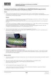
<strong>Anwendungshinweise</strong> - Käfighaltesystem CRS<br />
Application notes - Cage retaining system CRS<br />
3.0. Applikationshinweise zu Käfighaltesystem<br />
CRS (Norm 664x)<br />
3.0. Application notes to cage retaining<br />
system CRS (Standard 664x)<br />
3.1. Beschreibung des CRS 3.1. Description of CRS<br />
Beweglicher Käfighalter aus Leichtmetall mit Rückhaltesystem<br />
für Kugelkäfige aus Aluminium oder Messing für den<br />
Einbau in Säulen der Normen: 6509 / 6579.<br />
Wird das CRS bei jedem Hub belastet, d.h. wird bei jedem<br />
Hub komplett aus der Vorspannung ausgefahren, so sind<br />
vorzugsweise Aluminiumkäfige der Norm 761x zu verwenden,<br />
wobei das Halteband aus dem Käfig zu entfernen ist.<br />
Wird das CRS als Käfighalter zur Wartung vorgesehen und<br />
im Arbeitshub nicht belastet, so sind Messingkäfige mit<br />
Sicherungsring gegen das Käfigwandern der Norm 7631<br />
einzusetzen.<br />
Movable cage retainer in light metal with retaining system<br />
for the cage retainer for ball cages in aluminium or brass for<br />
mounting into pillars of Standards No. 6509 / 6579<br />
When the cage must run completely out of the preload with<br />
each stroke, our 761x-style aluminium ball cage is recommended.<br />
The anti-skid unit inside these cages should be<br />
removed.<br />
If the CRS is used as an assembly device, and does not<br />
carry the cage during the working stroke, our ball cages in<br />
brass with circlip (Standard 7631) could be used. The circlip<br />
prevents the cage from creeping during operation.<br />
3.2. Handling und Wartung 3.2. Handling and Maintenance<br />
Mit den Aussparungen an der Scheibe unten am CRS soll<br />
das Kippen des Werkzeugoberteils über die Säulen ermöglicht<br />
werden, ohne dass dabei das CRS Schaden nimmt.<br />
Die Scheibe muss vor dem Kippen lediglich so positioniert<br />
werden, dass eine der Aussparungen in die Kipprichtung<br />
orientiert ist.<br />
Das CRS wird in seiner obersten Position mechanisch gehalten.<br />
Dadurch kann das Werkzeugoberteil aus einer Seitwärtslage<br />
wieder auf die Säulen gekippt werden, ohne dass die<br />
Käfige über das Säulenende gelangen und durch das Werkzeuggewicht<br />
beschädigt werden. Der Haltemechanismus<br />
wirkt auf den letzten 3mm des CRS Hubes. Das CRS ist<br />
deshalb so auszulegen, dass unten immer der Sicherheitsabstand<br />
(S) von mindestens 6-10mm eingehalten<br />
ist, damit es im Arbeitshub nicht komplett in die Säule<br />
eingefahren wird (Nachschleifen berücksichtigen).<br />
Das CRS wird in jeder Position mechanisch am Ausfahren<br />
durch das Eigengewicht gehindert. Damit kann es beim Ein-<br />
und Ausbau auf der Presse nicht in die T-Nuten fallen und<br />
verklemmen. Der Transport des Werkzeugs wird durch das<br />
CRS nicht beeinträchtigt. Es ist innerhalb der Buchse in der<br />
unteren Platte gehalten und kann nicht vorstehen.<br />
Das CRS ist mit einem Stellring auf der Schraube versehen,<br />
welche die Einbautiefe genau definiert. Das CRS muss bis<br />
zum Anstehen auf dem Stellring festgezogen werden. Die<br />
Schraube sollte zur Sicherung mit Loctite gesichert werden.<br />
3.3. Längenbestimmung der Buchse,<br />
Säule und CRS<br />
With the recesses on the CRS disc, the flipping of the tool<br />
upper plate (on the bench) can be made possible without<br />
damaging the CRS. Before tilting the plate, simply position<br />
the disc so that one of the recesses is pointing in the same<br />
direction you will tilt.<br />
The CRS is mechanically locked in its uppermost (closed)<br />
position. This allows the tool upper plate to lean on the pillars<br />
without the cages hanging off the end of them, where they<br />
could be damaged by the tool weight. This holding mechanism<br />
engages in the last 3mm of the CRS stroke. Therefore,<br />
the CRS has to be laid out with a security distance (S)<br />
of 6-10mm, so that in the working stroke it does not<br />
completely move into the pillar (take the regrinding<br />
into consideration).<br />
The CRS will not extend under its own weight. Therefore, it<br />
will not fall into press T-slots, or get jammed when the tool<br />
is slid into or out of the press. Transporting the tool will be<br />
easier, because the CRS will not stick out of the bottom of<br />
the die shoe.<br />
The adjusting ring on the CRS screw establishes the installation<br />
length. The CRS must be tightened until it stops on the<br />
adjusting ring. The screw should be secured with Loctite to<br />
facilitate retention.<br />
3.3. Defining the length of the bushing,<br />
pillar and CRS<br />
Zweck der variablen Schraubenlänge beim CRS (Wert C) Purpose of the variable length of the CRS-screw (value C)<br />
Der Wert C wird aufgrund von Arbeitshub, Käfig-, respektive<br />
Buchsenlänge und Anwendung bestimmt. Dabei ist der Wert<br />
C so zu wählen, dass der Käfig noch auf einer minimalen<br />
Länge von 25 mm (ca. 3 Kugelreihen) auf der Säule geführt<br />
wird. Der Käfig ist so zu positionieren, dass sich der Einstich<br />
für die Montagehilfe auf der unteren Seite befindet.<br />
The value C is defined on the basis of the stroke, length of<br />
cage, resp. bushing and the application. In this regard, the<br />
value C has to be chosen in a way that the cage can move<br />
on the pillar on a minimum length of 25mm (approx. 3 rows<br />
of balls). The cage has to be positioned so that the groove<br />
for mounting aid is in the lower part.<br />
Änderungen vorbehalten V1<br />
39<br />
Specifications subject to change without prior notice