DT-X7 CI - Radix
DT-X7 CI - Radix
DT-X7 CI - Radix

Sie wollen auch ein ePaper? Erhöhen Sie die Reichweite Ihrer Titel.
YUMPU macht aus Druck-PDFs automatisch weboptimierte ePaper, die Google liebt.
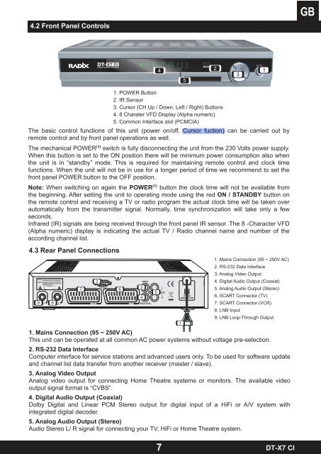
4.2 Front Panel Controls<br />
1. POWER Button<br />
2. IR Sensor<br />
3. Cursor (CH Up / Down, Left / Right) Buttons<br />
4. 8 Charater VFD Display (Alpha numeric)<br />
5. Common Interface slot (PCM<strong>CI</strong>A)<br />
The basic control functions of this unit (power on/off, Cursor fuction) can be carried out by<br />
remote control and by front panel operations as well.<br />
The mechanical POWER (1) switch is fully disconnecting the unit from the 230 Volts power supply.<br />
When this button is set to the ON position there will be minimum power consumption also when<br />
the unit is in “standby” mode. This is required for maintaining remote control and clock time<br />
functions. When the unit will not be in use for a longer period of time we recommend to set the<br />
front panel POWER button to the OFF position.<br />
Note: When switching on again the POWER (1) button the clock time will not be available from<br />
the beginning. After setting the unit to operating mode using the red ON / STANDBY button on<br />
the remote control and receiving a TV or radio program the actual clock time will be taken over<br />
automatically from the transmitter signal. Normally, time synchronization will take only a few<br />
seconds.<br />
Infrared (IR) signals are being received through the front panel IR sensor. The 8 -Character VFD<br />
(Alpha numeric) display is indicating the actual TV / Radio channel name and number of the<br />
according channel list.<br />
4.3 Rear Panel Connections<br />
19<br />
8<br />
7<br />
2<br />
6<br />
3<br />
4<br />
5<br />
4<br />
1. Mains Connection (95 ~ 250V AC)<br />
This unit can be operated at all common AC power systems without voltage pre-selection.<br />
2. RS-232 Data Interface<br />
Computer interface for service stations and advanced users only. To be used for software update<br />
and channel list data transfer from another receiver (master / slave).<br />
3. Analog Video Output<br />
Analog video output for connecting Home Theatre systems or monitors. The available video<br />
output signal format is “CVBS”.<br />
4. Digital Audio Output (Coaxial)<br />
Dolby Digital and Linear PCM Stereo output for digital input of a HiFi or A/V system with<br />
integrated digital decoder.<br />
5. Analog Audio Output (Stereo)<br />
Audio Stereo L/ R signal for connecting your TV, HiFi or Home Theatre system.<br />
7<br />
1<br />
5<br />
2<br />
3<br />
1. Mains Connection (95 ~ 250V AC)<br />
2. RS-232 Data Interface<br />
3. Analog Video Output<br />
4. Digital Audio Output (Coaxial)<br />
5. Analog Audio Output (Stereo)<br />
6. SCART Connector (TV)<br />
7. SCART Connector (VCR)<br />
8. LNB Input<br />
9. LNB Loop-Through Output<br />
1<br />
<strong>DT</strong>-<strong>X7</strong> <strong>CI</strong>