FLAIL MOWERS PRE-OPERATION Inspection - McConnel
FLAIL MOWERS PRE-OPERATION Inspection - McConnel
FLAIL MOWERS PRE-OPERATION Inspection - McConnel
You also want an ePaper? Increase the reach of your titles
YUMPU automatically turns print PDFs into web optimized ePapers that Google loves.
Publication: 530<br />
January 2008<br />
Part No. 41571.30<br />
Revision: 10.09.10<br />
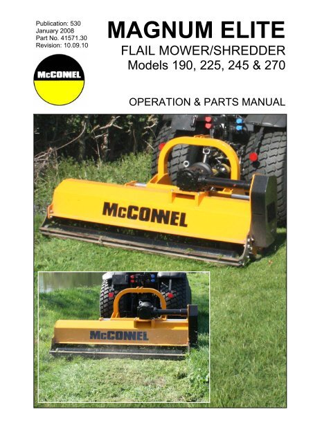
MAGNUM ELITE<br />
<strong>FLAIL</strong> MOWER/SHREDDER<br />
Models 190, 225, 245 & 270<br />
<strong>OPERATION</strong> & PARTS MANUAL
IMPORTANT<br />
VERIFICATION OF WARRANTY REGISTRATION<br />
DEALER WARRANTY INFORMATION & REGISTRATION VERIFICATION<br />
It is imperative that the selling dealer registers this machine with <strong>McConnel</strong> Limited before<br />
delivery to the end user – failure to do so may affect the validity of the machine warranty.<br />
To register machines go to the <strong>McConnel</strong> Limited web site at www.mcconnel.com, log<br />
onto ‘Dealer Inside’ and select the ‘Machine Registration button’ which can be found in<br />
the Service Section of the site. Confirm to the customer that the machine has been<br />
registered in the section below.<br />
Should you experience any problems registering a machine in this manner please contact<br />
the <strong>McConnel</strong> Service Department on 01584 875848.<br />
Registration Verification<br />
Dealer Name: ……………………..…………………………………………………………….<br />
Dealer Address: …….………………………………………………………………………….<br />
Customer Name: ……………………..…………………………………………………………<br />
Date of Warranty Registration: ……/……/...…… Dealer Signature: ………………..……<br />
NOTE TO CUSTOMER / OWNER<br />
Please ensure that the above section above has been completed and signed by the selling<br />
dealer to verify that your machine has been registered with <strong>McConnel</strong> Limited.<br />
IMPORTANT: During the initial ‘bedding in’ period of a new machine it is the customer’s responsibility<br />
to regularly inspect all nuts, bolts and hose connections for tightness and re-tighten if required. New<br />
hydraulic connections occasionally weep small amounts of oil as the seals and joints settle in – where<br />
this occurs it can be cured by re-tightening the connection – refer to torque settings chart below. The<br />
tasks stated above should be performed on an hourly basis during the first day of work and at least<br />
daily thereafter as part of the machines general maintenance procedure.<br />
TORQUE SETTINGS FOR HYDRAULIC FITTINGS<br />
HYDRAULIC HOSE ENDS PORT ADAPTORS WITH BONDED SEALS<br />
BSP Setting Metric BSP Setting Metric<br />
1/4” 18 Nm 19 mm 1/4” 34 Nm 19 mm<br />
3/8” 31 Nm 22 mm 3/8” 47 Nm 22 mm<br />
1/2” 49 Nm 27 mm 1/2” 102 Nm 27 mm<br />
5/8” 60 Nm 30 mm 5/8” 122 Nm 30 mm<br />
3/4” 80 Nm 32 mm 3/4” 149 Nm 32 mm<br />
1” 125 Nm 41 mm 1” 203 Nm 41 mm<br />
1.1/4” 190 Nm 50 mm 1.1/4” 305 Nm 50 mm<br />
1.1/2” 250 Nm 55 mm 1.1/2” 305 Nm 55 mm<br />
2” 420 Nm 70 mm 2” 400 Nm 70 mm
WARRANTY POLICY<br />
WARRANTY REGISTRATION<br />
All machines must be registered, by the selling dealer with <strong>McConnel</strong> Ltd, before delivery to the end<br />
user. On receipt of the goods it is the buyer’s responsibility to check that the Verification of Warranty<br />
Registration in the Operator’s Manual has been completed by the selling dealer.<br />
1. LIMITED WARRANTIES<br />
1.01. All machines supplied by <strong>McConnel</strong> Limited are warranted to be free from defects in material<br />
and workmanship from the date of sale to the original purchaser for a period of 12 months,<br />
unless a different period is specified.<br />
1.02. All spare parts supplied by <strong>McConnel</strong> Limited are warranted to be free from defects in material<br />
and workmanship from the date of sale to the original purchaser for a period of 6 months.<br />
1.03. The manufacturer will replace or repair for the purchaser any part or parts found, upon<br />
examination at its factory, to be defective under normal use and service due to defects in<br />
material or workmanship. Returned parts must be complete and unexamined.<br />
1.04. This warranty does not apply to any part of the goods, which has been subjected to improper or<br />
abnormal use, negligence, alteration, modification, fitment of non-genuine parts, accident<br />
damage, or damage resulting from contact with overhead power lines, damage caused by<br />
foreign objects (e.g. stones, iron, material other than vegetation), failure due to lack of<br />
maintenance, use of incorrect oil or lubricants, contamination of the oil, or which has served its<br />
normal life. This warranty does not apply to any expendable items such as blades, flails, flap<br />
kits, skids, soil engaging parts, shields, guards, wear pads or pneumatic tyres.<br />
1.05. Temporary repairs and consequential loss - i.e. oil, downtime and associated parts are<br />
specifically excluded from the warranty.<br />
1.06. Warranty on hoses is limited to 12 months and does not include hoses which have suffered<br />
external damage. Only complete hoses may be returned under warranty, any which have been<br />
cut or repaired will be rejected.<br />
1.07. Machines must be repaired immediately a problem arises. Continued use of the machine after a<br />
problem has occurred can result in further component failures, for which <strong>McConnel</strong> Ltd cannot<br />
be held liable, and may have safety implications.<br />
1.08. Except as provided herein, no employee, agent, dealer or other person is authorised to give any<br />
warranties of any nature on behalf of <strong>McConnel</strong> Ltd.<br />
1.09. For machine warranty periods in excess of 12 months the following additional exclusions shall<br />
apply:<br />
1) Hoses, external seals, exposed pipes and hydraulic tank breathers.<br />
2) Filters.<br />
3) Rubber mountings.<br />
4) External electric wiring.<br />
1.10. All service work, particularly filter changes, must be carried out in accordance with the<br />
manufacturer’s service schedule. Failure to comply will invalidate the warranty. In the event of a<br />
claim, proof of the service work being carried out may be required.<br />
NB Warranty cover will be invalid if any non-genuine parts have been fitted or used. Use of<br />
non-genuine parts may seriously affect the machine’s performance and safety. <strong>McConnel</strong> Ltd<br />
cannot be held responsible for any failures or safety implications that arise due to the use of<br />
non-genuine parts.
2. REMEDIES AND PROCEDURES<br />
2.01. The warranty is not effective unless the Selling Dealer registers the machine, via the <strong>McConnel</strong><br />
web site and confirms the registration to the purchaser by completing the confirmation form in<br />
the operator’s manual.<br />
2.02. Any fault must be reported to an authorised <strong>McConnel</strong> dealer as soon as it occurs. Continued<br />
use of a machine, after a fault has occurred, can result in further component failure for which<br />
<strong>McConnel</strong> Ltd cannot be held liable.<br />
2.03. Repairs should be undertaken within two days of the failure. Claims submitted for repairs<br />
undertaken more than 2 weeks after a failure has occurred, or 2 days after the parts were<br />
supplied will be rejected, unless the delay has been authorised by <strong>McConnel</strong> Ltd.<br />
2.04. All claims must be submitted, by an authorised <strong>McConnel</strong> Service Dealer, within 30 days of the<br />
date of repair.<br />
2.05. Following examination of the claim and parts the manufacture will pay, at their discretion, for<br />
any valid claim the cost of any parts and an appropriate labour allowance if applicable.<br />
2.06. The submission of a claim is not a guarantee of payment.<br />
2.07. Any decision reached by <strong>McConnel</strong> Ltd. is final.<br />
3. LIMITATION OF LIABILITY<br />
3.01. The manufacturer disclaims any express (except as set forth herein) and implied warranties<br />
with respect to the goods including, but not limited to, merchantability and fitness for a particular<br />
purpose.<br />
3.02. The manufacturer makes no warranty as to the design, capability, capacity or suitability for use<br />
of the goods.<br />
3.03. Except as provided herein, the manufacturer shall have no liability or responsibility to the<br />
purchaser or any other person or entity with respect to any liability, loss, or damage caused or<br />
alleged to be caused directly or indirectly by the goods including, but not limited to, any indirect,<br />
special, consequential, or incidental damages resulting from the use or operation of the goods<br />
or any breach of this warranty. Notwithstanding the above limitations and warranties, the<br />
manufacturer’s liability hereunder for damages incurred by the purchaser or others shall not<br />
exceed the price of the goods.<br />
3.04. No action arising out of any claimed breach of this warranty or transactions under this warranty<br />
may be brought more than one (1) year after the cause of the action has occurred.<br />
4. MISCELLANEOUS<br />
4.01. The manufacturer may waive compliance with any of the terms of this limited warranty, but no<br />
waiver of any terms shall be deemed to be a waiver of any other term.<br />
4.02. If any provision of this limited warranty shall violate any applicable law and is held to be<br />
unenforceable, then the invalidity of such provision shall not invalidate any other provisions<br />
herein.<br />
4.03. Applicable law may provide rights and benefits to the purchaser in addition to those provided<br />
herein.
We,<br />
DECLARATION OF CONFORMITY<br />
Conforming to EU Machinery Directive 2006/42/EC<br />
McCONNEL LIMITED, Temeside Works, Ludlow, Shropshire SY8 1JL, UK<br />
Hereby declare that:<br />
The Product; Tractor Mounted Flail Mower<br />
Product Code; MA19, MF19, MA22, MA24, MA27<br />
Serial No. & Date ………………………………… Type …………………………<br />
Manufactured in; Slovenija<br />
Complies with the required provisions of the Machinery Directive 2006/42/EC<br />
The machinery directive is supported by the following harmonized standards;<br />
� BS EN ISO 14121-1 (2007) Safety of machinery - Risk assessment, Part 1:<br />
Principles Part 2: practical guide and examples of methods.<br />
� BS EN ISO 12100-1 (2010) Safety of machinery - Part 1: Basic terminology and<br />
methodology Part 2: Technical principles.<br />
� BS EN 349(1993)+ A1 (2008) Safety of machinery - Minimum distances to avoid the<br />
entrapment with human body parts.<br />
� BS EN 953 (1998) Safety of machinery - Guards General requirements for the<br />
design and construction of fixed and movable guards.<br />
� BS EN 982(1996)+ A1 (2008) Safety requirements for fluid power systems and their<br />
components. Hydraulics<br />
McCONNEL LIMITED operates an ISO 9001:2008 quality management system,<br />
certificate number: FM25970.<br />
This system is continually assessed by the;<br />
British Standards Institution (BSI), Beech House, Milton Keynes, MK14 6ES, UK<br />
BSI is accredited by UK Accreditation Service, accreditation number: UKAS 003.<br />
The EC declaration only applies if the machine stated above is used in<br />
accordance with the operating instructions.<br />
Signed …………………................ Responsible Person<br />
on behalf of McCONNEL LIMITED<br />
Status: General Manager Date: May 2011
<strong>FLAIL</strong> MOWER INSPECTION AND MAINTENANCE<br />
A daily equipment inspection of the tractor and mower should be conducted before the<br />
equipment is used. You may use the inspection sheets to assist with these daily<br />
inspections. Any damaged or missing guards should be repaired or replaced before<br />
operating the mower. Failure to repair the damaged shield can result in objects being<br />
thrown from the mower and possibly hitting the operator or bystander.<br />
Inspect the Mower for Safe Operating Condition<br />
� Make sure the driveline guards and shielding are in place and in good repair.<br />
� Inspect the chain guards, flexible and/or solid defector thrown object shielding to<br />
assure that they are in place on the front and rear of the mower deck and in good<br />
repair. Repair or replace any damaged or missing thrown object shields.<br />
� Ensure the mower cutting height is set high enough to reduce the possibility of the<br />
mower blades contacting the ground. Actual height will be dependent on the ground<br />
conditions. Increase the height when working in rough or undulating conditions.<br />
� Inspect for broken, chipped, bent, missing, or severely worn blades. Replace<br />
damaged blades before operating the mower. Ensure the blade retaining bolts and<br />
fasteners are secure and tight.<br />
� Lubricate the driveline universal joints and telescoping members daily.<br />
� Inspect the wheel lug bolt/nuts to assure that they are tight.<br />
� If mower is equipped with pneumatic tires, make sure they have the required air<br />
pressure.<br />
� Inspect for worn or damaged decals and safety instructions. Replace unreadable,<br />
damaged or missing safety decals.<br />
� Follow the operator’s manual(s) inspection and maintenance instructions for<br />
lubricating parts, and keeping thrown object shielding, driveline guards, rotating<br />
parts shields, mower blades and decals in good repair.<br />
Inspect the Tractor for Safe Operating Condition:<br />
� Inspect the controls, lights, SMVs (Slow Moving Vehicle sign), seat belts, and<br />
ROPS to assure that they are in place and in good working order.<br />
� Be sure the tires, wheels, lug bolts/nuts are in good condition.<br />
� Make sure the tractor brakes and steering are in proper operating condition.<br />
� Follow the operator’s manual(s) inspection and maintenance procedures for<br />
keeping the tractor in good and safe condition before operating.<br />
The inspection sheet on the following page should be kept in this book as a record. A<br />
second sheet is included for you to cut out and photocopy or the inspection sheets can be<br />
downloaded from our website at;<br />
http://www.mcconnel.com/support/aftersales/default.aspx?nav=After Sales
<strong>FLAIL</strong> <strong>MOWERS</strong> <strong>PRE</strong>-<strong>OPERATION</strong> <strong>Inspection</strong><br />
Mower ID ________________ Date: _______________ Shift: _______________<br />
WARNING Before conducting the inspection, make sure the tractor engine is off, with the key<br />
removed, all rotation has stopped and the tractor is in park with the parking brake<br />
engaged. Make sure the mower is resting on the ground or is securely blocked up and<br />
supported and all hydraulic pressure has been relieved.<br />
Item<br />
The Operator’s Manual is in the Canister on the mower<br />
All Warning Decals are in place, clean and legible<br />
The Hyd. Cylinder pins are tight and correctly secured<br />
The Hyd Cylinder hose connections are tight<br />
There are no oil leaks<br />
There are no damaged hoses<br />
Flails are not missing chipped, broken or excessively worn<br />
The Flail bolts are tight<br />
The Front & Rear Flaps are fitted and in good condition<br />
The Skid shoes are in good condition & tight<br />
The Rotor Bearings are in good condition and greased<br />
The Roller bearings are in good condition and greased<br />
There are no cracks or holes in flail casing<br />
The drive line/gearbox shaft guard is in good condition<br />
The drive line/gearbox shaft guard is correctly secured<br />
Driveline telescoping members & u-joints are lubricated<br />
Driveline yokes are securely attached to tractor & mower<br />
All linkage mounting pins are securely fastened<br />
Condition at<br />
start of shift<br />
Operators Signature: ___________________________________________<br />
DO NOT OPERATE an UNSAFE TRACTOR or MOWER<br />
Specific Comments if not O.K.
TRACTOR <strong>PRE</strong>-<strong>OPERATION</strong> <strong>Inspection</strong><br />
Power Arm ID ________________ Date: _______________ Shift: _______________<br />
WARNING Before conducting the inspection, make sure the tractor engine is off, the key is removed<br />
all rotation has stopped and the tractor is in park with the parking brake engaged. Any<br />
implement attached to the tractor is firmly on the ground.<br />
Item<br />
The flashing lights function properly.<br />
All lights are clean and working correctly<br />
All cab windows are clean and wipers working correctly<br />
The SMV sign, where required, is clean and visible.<br />
The tyres are in good condition with correct pressure.<br />
The wheel nuts are tight.<br />
The tractor brakes are in good condition.<br />
The steering linkage is in good condition.<br />
There are no visible oil leaks.<br />
The hydraulic controls function properly.<br />
The ROPS or ROPS cab is in good condition.<br />
The seatbelt is in place and in good condition.<br />
The 3-point hitch is in good condition.<br />
The drawbar/pick up hook is secure & in good condition<br />
The PTO master shield is in place.<br />
The engine oil level is full.<br />
The brake fluid level is full.<br />
The power steering fluid level is full.<br />
The fuel level is adequate.<br />
The engine coolant fluid level is full.<br />
The radiator & oil cooler are free of debris.<br />
The air filter is in good condition<br />
Condition at<br />
start of shift<br />
Operators Signature: ___________________________________________<br />
DO NOT OPERATE an UNSAFE TRACTOR or MOWER<br />
Specific Comments if not O.K.
LIST OF CONTENTS<br />
OPERATOR SECTION<br />
General Information 1<br />
Machine Description & Purpose of Use 2<br />
Machine Identification 2<br />
Technical Data 3<br />
Technical Specifications 3<br />
Safety Features 4<br />
Safety Information 5<br />
Safety Decals 6<br />
Vehicle/Tractor Preparation 7<br />
Machine Attachment 8<br />
PTO Shaft 9<br />
Setting Up and Adjustment 10<br />
Flails 10<br />
Offsetting 11<br />
Drive Belts 12<br />
Pre-Operational Checks 13<br />
Operation 14<br />
Detachment and Storage 15<br />
Maintenance 16<br />
Troubleshooting 19<br />
PARTS SECTION<br />
Mower Assembly 22<br />
Decal Kit – Magnum 190 Elite 28<br />
Decal Kit – Magnum 225 Elite 29<br />
Decal Kit – Magnum 245HD Elite 30<br />
Decal Kit – Magnum 270HD Elite 31
GENERAL INFORMATION<br />
Always read this manual before fitting or operating the machine – whenever any doubt<br />
exists contact your dealer or the <strong>McConnel</strong> Service Department for advice and assistance.<br />
Use only <strong>McConnel</strong> Genuine Service Parts on <strong>McConnel</strong> Equipment and Machines<br />
DEFINITIONS – The following definitions apply throughout this manual:<br />
WARNING<br />
An operating procedure, technique etc., which –<br />
can result in personal injury or loss of life if not observed carefully.<br />
CAUTION<br />
An operating procedure, technique etc., which –<br />
can result in damage to either machine or equipment if not observed carefully.<br />
NOTE<br />
An operating procedure, technique etc., which –<br />
is considered essential to emphasis.<br />
LEFT AND RIGHT HAND<br />
This term is applicable to the machine when attached to the tractor and is viewed<br />
from the rear – this also applies to tractor references.<br />
MACHINE & DEALER INFORMATION<br />
Record the Serial Number of your machine on this page and always quote this number when<br />
ordering parts. Whenever information concerning the machine is requested remember also to state<br />
the make and model of tractor to which the machine is fitted.<br />
Machine Serial Number:<br />
Machine Model details:<br />
Dealer Name:<br />
Dealer Address:<br />
Dealer Telephone No:<br />
Dealer Email Address:<br />
1<br />
Installation Date:
MACHINE DESCRIPTION & PURPOSE OF USE<br />
The Magnum Elite series of machines are ‘3 -point linkage’ tractor mounted mid-sized flail<br />
mower/shredders suitable for tractors of 50HP and above. Designed primarily for the<br />
mulching of grasses, brambles, bushes, br anches, vines, and general crop residues t heir<br />
tough construction and choice of working wid ths of 1.9m, 2.2m, 2.4m or 2.7m wit h<br />
offsetting capability of up to 400mm make t hem ideal for both agricultural users and<br />
general contractors alike.<br />
These machines should only be used to perform tasks for which they were designed – use<br />
of the machine for any other function may be both dangerous to persons and damaging to<br />
components and is therefore not advisable.<br />
MACHINE IDENTIFICATION<br />
Each machine is fitted with an identification plate with the following information:<br />
1. Machine (Part Number)<br />
2. Machine Serial No.<br />
3. Machine Weight<br />
When ordering spares or replacement parts from<br />
your local dealer it is im portant to quote both Part<br />
Number and Serial Nu mber as stated on the<br />
identification plate so the machine and model can<br />
be quickly and correctly identified.<br />
2<br />
Machine Identification Plate
TECHNICAL DATA<br />
COMPONENT IDENTIFICATION<br />
1. Frame<br />
2. Gearbox<br />
3. Sliding Tubes<br />
4. 3-Point Linkage<br />
5. Belt Drive / Belt Guard<br />
6. Skid<br />
7. Rear Roller<br />
8. Protection Flaps<br />
9. Stand Leg<br />
TECHNICAL SPECIFICATIONS<br />
SPECIFICATION ELITE 190 ELITE 225 ELITE 245 ELITE 270<br />
Working Width (mm) 1920 2270 2420 2720<br />
Tractor Power Requirement (HP) 50 60 74 80<br />
PTO Speed (RPM) 540 540 540 1000<br />
Hammer Blades (No.) 24 28 30 34<br />
Y-Blades (No.) 48 56 60 68<br />
Machine Weight (kg) 410/430 462/487 495/515 525/545<br />
Offset Capability (mm) 400 400 400 400<br />
Linkage (Type) 3-point Cat 2 3-point Cat 2 3-point Cat 2 3-point Cat 2<br />
Machine Width (mm) 2080 2430 2630 2880<br />
OPTIONAL EQUIPMENT<br />
The following options are available on these machines:<br />
• Front Linkage<br />
• Hammer Flails<br />
• Y-Blade Flails<br />
The cutting capability of the each particular ty pe of flail will be dep endant on the sort and<br />
hardness of the material being cut, but in general the following cutting thicknesses apply:<br />
Y-blade flails – for materials up to a maximum of 30mm diameter.<br />
Hammer flails – for materials up to a maximum of 45mm diameter.<br />
NOISE LEVEL<br />
The sound level of this machine, as measured at the operator’s ear, is within the range of<br />
70 to 90 dB when the rear window of t he tractor is open. We recommend that ear<br />
protectors are worn and the tractor windows kept clos ed at all times when operating t his<br />
machine.<br />
3
SAFETY FEATURES<br />
LOCATION OF MACHINE SAFETY FEATURES<br />
1. PTO Shaft Shields<br />
2. Drive Belt Guard<br />
3. Side Skids<br />
4. Protection Flaps<br />
5. Safety Decals<br />
4
SAFETY INFORMATION<br />
General safety rules:<br />
▲ Always read and follow the instructions for the use and maintenance of the machine<br />
before carrying out any work operations or servicing tasks.<br />
▲ Improper use of the machine is both hi ghly dangerous to persons and damaging to t he<br />
machine components – only use the machine for its designated task.<br />
▲ Both operators and th e maintenance fitters should be familiar with the mac hine and<br />
fully aware of dangers surrounding improper use or incorrect repairs.<br />
▲ Before starting, check s to both tractor and machine m ust be carried out as regards:<br />
functionality, road safety, accident prevention rules.<br />
▲ Even when using the machine c orrectly, stones or other objects may be thrown a long<br />
distance. Therefore nobody must stand within the danger area. Special attention mus t<br />
be paid when working near roads or buildings.<br />
▲ Use tractor’s fitted with safety cabs.<br />
▲ The condition of flails and of machine guards must be checke d before beginning the<br />
daily work - they must be replaced if damaged or missing before you use the machine.<br />
▲ During checks or repairs, make sure nobody could start the machine by mistake.<br />
▲ Never wear loose or fluttering clothes.<br />
▲ Never carry passengers on the tractor.<br />
▲ Never carry passengers on the machine.<br />
▲ Never connect the power takeoff with the engine running.<br />
▲ Never approach the machine until the rotor has completely stopped.<br />
▲ Do not enter the working zone of the PTO shaft. It is dangerous to approach the<br />
rotating parts of a machine.<br />
▲ Keep the PTO shaft guard in good condition.<br />
▲ Before starting, check the surrounding area for the likely presence of childr en and/or<br />
animals.<br />
▲ Do not stand near the machine when it is operating.<br />
▲ The PTO shaft must be asse mbled and disassembled only with the engine stopp ed<br />
and the starting key removed.<br />
▲ Before connecting the power takeoff, check that the speed and the rotational direction<br />
correspond to those of the machine.<br />
▲ Immediately replace missing or damaged safety decals.<br />
▲ Before leaving the tractor with the machine attached, proceed as follows:<br />
1. Disconnect the power takeoff,<br />
2. Put the machine steadily on the ground using the tractor’s hydraulic lift.<br />
3. Apply the hand brake and, if the ground is steeply sloping, wedge the tractor.<br />
4. Remove the starting key.<br />
5
Transportation Safety<br />
▲ In transport, reduce speed, especially on bumpy roads, the weight of the machine may<br />
render driving difficult and damage the machine itself.<br />
▲ Ensure the levers that operate the hydraulic lift are locked, to avoid the lowering of the<br />
machine during transport.<br />
▲ When driving on public roads, respect all road rules in force.<br />
▲ Never transport the machine with the rotor running, even for short distances.<br />
Operating Safety<br />
▲ Pay special attention when working with the machine not to touch fixed objects such as<br />
road drain, walls, shaf ts, kerbs, guard rails, tracks etc. This could cause the breakage<br />
of the flails, which would be thrown out of the machine at very high speed.<br />
▲ If wires, ropes or chains should become entangl ed in the rotor stop immediately to<br />
prevent damage or dangerous s ituations; stop the rotor and the tractor, take out t he<br />
starting key. Put work ing gloves on; clear the rotor with the aid of pliers or s hears. Do<br />
not try to disentangle by inverting the rotational direction of the rotor.<br />
▲ Do not use the machine when excess ive vibration is experienced, as this m ay cause<br />
breakage and serious damage - find the cause of the vibration and eliminate it before<br />
using the machine again.<br />
Although the information given here covers a wide range of safety subjects, it is impossible to<br />
predict every eventuality that can occur under differing circumstances whilst operating this machine.<br />
No advice given here can replace ‘good common sense’ and ‘total awareness’ at all times, but will go<br />
a long way towards the safe use of your <strong>McConnel</strong> machine.<br />
SAFETY DECALS<br />
1. Always switch machine off, remove st arting key and read inst ruction manual before<br />
performing service or maintenance work on the machine.<br />
2. Keep a safe distance from the machine at all times - risk from projection of objects.<br />
3. Risk of hand injury – always ens ure all guard are fitted and in p lace when machine<br />
is operating.<br />
4. Risk of feet injury – keep at a safe distance from the machine when it is operating.<br />
5. Never stand or ride on the machine.<br />
6
VEHICLE / TRACTOR <strong>PRE</strong>PARATION<br />
We recommend vehicles are fitted with<br />
cabs using ‘safety glass’ windows and<br />
protective guarding when used with our<br />
machines.<br />
Fit Operator Guard (part no. 73 13 324)<br />
using the hooks provided. Shape the mesh<br />
to cover all vulnerable areas.<br />
Remember the driver must be looking<br />
through mesh and/or polycarbonate glazing<br />
when viewing the machine in all positions - unless the vehicle/ cab manufacturer can<br />
demonstrate that the penet ration resistance is equivalent to , or higher than, that provided<br />
by mesh/polycarbonate glazing. If the tractor has a roll bar onl y, a frame must be made to<br />
carry both mesh and polycarbonate glaz ing. The operator should als o use personal<br />
protective equipment to reduce the risk of seri ous injury such as; eye protection (mesh<br />
visor to EN1731 or safety glasses to EN166), hearing protection to EN352, s afety helmet<br />
to EN297, gloves, filter mask and high visibility clothing.<br />
Vehicle Ballast<br />
It is imperative when attaching ‘third-party ’ equipment to a vehicle that the maximum<br />
possible stability of the machine and vehicle combination is achiev ed – this can be<br />
accomplished by the utilisation of ‘ballas t’ in order to counter-balance the additio nal<br />
equipment added.<br />
Front weights may be required for rear mount ed machines t o place 15% of total outfit<br />
weight on the front axle for stable transport on the road and to reduce ‘crabbing’ due to the<br />
drag of the cutting unit when working on the ground.<br />
Where a machine works to the side of the tractor rear weights may be required to maintain<br />
a reasonable amount of rear axle load on the opposing wheel.<br />
All factors must be addressed in order to match the type and nature of the equipment<br />
added to the circumstances under which it will be used - factors that effect stability are:<br />
• Centre of gravity of the tractor/machine combination.<br />
• Geometric conditions, e.g. position of the cutting head and ballast.<br />
• Weight, track width and wheelbase of the tractor.<br />
• Acceleration, braking, turning and the rela tive position of the cutting unit during these<br />
operations.<br />
• Ground conditions, e.g. slope, grip, load capability of the soil/surface.<br />
• Rigidity of implement mounting.<br />
Suggestions to increase stability:<br />
• Increasing rear wheel track - a vehicle with a wider wheel track is more stable.<br />
• Ballasting the wheel; it is preferable to use external we ights but liquid can be added to<br />
around 75% of the tyre volume – water with anti-freeze or the heavier Calcium Chloride<br />
alternative can be used.<br />
• Addition of weights – care should be taken in selecting the location of the weights to<br />
ensure they are added to a position that offers the greatest advantage.<br />
• Front axle locking, check with tractor manufacturer.<br />
The advice above is offered as a guide for stability only and is not a guide to vehicle strength. It is<br />
therefore recommended that you consult your vehicle manufacturer or local dealer to obtain specific<br />
advice on this subject, additionally advice should be sought from a tyre specialist with regard to tyre<br />
pressures and ratings suitable for the type and nature of the machine you intend to fit.<br />
7
ATTACHING THE MACHINE TO THE TRACTOR<br />
Attachment of the machine to the tractor should always be performed on a firm level site.<br />
Before attachment always ensure:<br />
• The machine is in good condition.<br />
• All safety guards are in good working condition and correctly fitted.<br />
• All flails are correctly fitted and undamaged.<br />
• Lubrication points are well greased and the gearbox oil level is correct.<br />
• Drive belts are tensioned correctly.<br />
• The tractor PTO rpm and direction of rotation correspond to that of the machine.<br />
ATTACHMENT OF THE MOWER<br />
Drive the tractor ‘squarely’ up to the machine.<br />
Position the tractors lower li nkage at a height where it is approximately in line with t he<br />
lower linkage points (A) on the machine – refer to photo below.<br />
Drive tractor slowly towards the machine until the lower linkage points correspond.<br />
Fit linkage pins and secure with spring clips.<br />
Fit top link to upper linkage point (B) – this may be floating or fixed depending on the work<br />
terrain - refer to set up and adjustment page for specific details on this subject.<br />
Raise the machine slightly on the tractors hy draulics – adjust top link to bring the machine<br />
into the perpendicular position.<br />
Fit check chains a nd/or stabilisers to trac tor lower links to cen tralise and secure the<br />
machine in position.<br />
Fit PTO Shaft and attach torque chains – refer to following page for details of shaft<br />
measurement.<br />
Attach hydraulic hoses - hydraulic sideshift models only.<br />
Machine Linkage<br />
A – Lower linkage points<br />
B – Upper linkage point<br />
8
PTO SHAFT<br />
PTO SHAFT MEASUREMENT<br />
Measure the PTO shaft and cut to the<br />
dimension shown – the finished length of the<br />
PTO shaft should be 75mm (3”) less than the<br />
measured distance ‘ A’ - between tractor<br />
shaft and gearbox stub shaft - to enable<br />
fitting.<br />
NOTE: For subsequent use with different<br />
tractors measure again, there must be a<br />
minimum shaft overlap of 150mm (6”).<br />
Fit PTO in position and attach the torque<br />
chains to a convenient location to prevent<br />
the shaft guards from rotating.<br />
PTO SHAFT LENGTH ADJUSTMENT<br />
1. Shorten outer plastic tube to 40mm<br />
less than the shortest envisaged shaft<br />
length.<br />
2. Remove the marked tube.<br />
3. Remove same length from inner<br />
plastic tube and metal shaft profiles<br />
(inner and outer).<br />
4. De-burr all edges and remove ‘swarf’<br />
to ensure smooth operation.<br />
Approximate overlap length of PTO shaft with machine lowered to the ground ▲<br />
Approximate gap length of PTO protection tube with machine in working position ▲<br />
Fit torque chains to shaft guards to prevent rotation ►<br />
9
TOP LINKAGE<br />
The machines top linkage point (B) has two working modes; floating and fixed – refer to<br />
photo below.<br />
Top linkage working positions ►<br />
Floating position (B1) should always be<br />
used when working on hilly or uneven<br />
terrain to protect t he machine and linkage<br />
from damage.<br />
Fixed position (B2) may be used when<br />
working on even leve l terrain such as<br />
playing fields and other similar areas that<br />
present a lower degree of stress on the<br />
linkage.<br />
WARNING:<br />
Always use top linkage floating position (B1) when working on hilly, sloping or undulating<br />
terrain.<br />
SETTING UP AND ADJUSTMENT<br />
The height of cut is dependent on working<br />
conditions and volume of material. The cutting<br />
height can be regulated with the hydraulic<br />
system on the tractor and/or rear roller<br />
adjustment – see photo opposite.<br />
The minimum height of cut should be between<br />
1 – 3cm.<br />
10<br />
NOTE: The machine must always run on the<br />
rear roller not the side skids – side skids are a<br />
protection feature and in normal working<br />
conditions remain clear of the ground.<br />
Do not allow the rotor flails to contact the<br />
ground - set roller height to allow a minimum<br />
flail to ground clearance of 1 to 3cm.
OFFSETTING<br />
The machine can be placed into an offset position to allow for work beyond the width of the<br />
tractor – depending on the particular specification of the machine offsetting operation will<br />
either be manual or hydraulic.<br />
Manual adjustment is performed by removal of the locking pin and ph ysically sliding the<br />
unit sideways before replacing the pin when the desired offset position is achieved.<br />
On machines fitted with hydraulic offset, adjustment to the required position can be carried<br />
out from the tractor cab by operation of the hydraulic sideshift ram.<br />
In both cases the machines must be rais ed clear of the ground to allow for free sid eways<br />
movement.<br />
DANGER: Ensure the machine is switched off and the rotor stationary when moving manual<br />
machines into the offset position – never attempt to perform this procedure with the machine<br />
running.<br />
<strong>FLAIL</strong>S<br />
Manual Offset Model – Locking pin Hydraulic Offset Models – Ram location<br />
As standard, the machine is equipped with Ha mmer type flails, but as an option can be<br />
fitted with Y-blade flails. The hammer type flails are more suited to harder working with the<br />
ability to cut materials up to 45mm (1¾”) diameter. Y-blade flails can cut up to 30mm (1¼”)<br />
diameter material – these figures are under normal use and may differ depending on the<br />
type and nature of the material being cut.<br />
The design of the mower is su ch that during work the roto r unit cuts the material and<br />
projects it upwards into the fr ame, as the material falls back into the rotor it is cut again<br />
several times until it is small enough to be discharged from the rear of the machine.<br />
Hammer Flails Y-Blade Flails<br />
The rotor unit should be inspect ed on a daily basis prior to work to check for damaged or<br />
missing flails – always replace damaged or missing flails immediately. Flail bolts should be<br />
checked for tightness on a regular basis and re-tightened as required before attempting to<br />
use the machine.<br />
WARNING: Checking of rotor components should only be carried out with tractors engine switched<br />
off, starting key removed and the PTO shaft disconnected. Always ‘prop up’ the machine using<br />
suitable supports before attempting to inspect or work on components underneath it.<br />
11
DRIVE BELTS<br />
BELT TENSION<br />
It is important for both optimal machine performance and long lasting belt life that belts are<br />
correctly tensioned at all times. T ension is correct when a force of 10 kg exerted on the<br />
belts at their mid-point between the upper and lower pulleys deviates the belts by 15mm.<br />
If the belts require tensioning follow the procedure stated below.<br />
After an initial first 2 hours of work check belt tension and taper locks (indicated 1 & 2 in the photo<br />
below right) – tighten if required.<br />
Belt Tension – 15mm deviation under<br />
10kg pressure at mid-point of belt run<br />
BELT ADJUSTMENT<br />
Adjustment of the belt tensi on is performed by loosening t he adjuster locking nut (A) and<br />
slackening half-shaft lock bolt (B) along wit h the four gearbox mounting bolts (C) – refer to<br />
photos below. Adjuster bolt (D) can then be turned to increase or decrease belt tension<br />
until belt deviation matches the required measurement – see above. Belt tensioning should<br />
be performed when t he belts are cold. Re-tighten bolts ‘B’ and ‘C’ a nd locknut ‘A’ when<br />
belt tension is correct.<br />
Location of Belt Tension Adjusters<br />
12<br />
Taper Locks – check tightness on new<br />
machines after initial 2 hours of work<br />
Location of Gearbox Mounting Bolts<br />
WARNING: Checking of belts and drive components should only be carried out with tractors engine<br />
switched off, starting key removed and the PTO shaft disconnected. Never attempt to run the<br />
machine with the belt guard removed – Replace guard after tensioning before starting the machine.
<strong>PRE</strong>-<strong>OPERATION</strong>AL CHECKS<br />
Before commencing work with the machine the following checks should be performed:<br />
• Make a visual inspection of the machine to ensure it is in good operational condition.<br />
• Check all safety guarding is in position and in full working order.<br />
• Check rotor for missing or damaged flails and replace if required.<br />
• Check all greasing points are well lubricated.<br />
• Check gearbox oil level.<br />
• Check belt tension and adjust if required.<br />
• Check PTO speed and direction match that of the machine.<br />
13
<strong>OPERATION</strong><br />
Ensure that the operator is suit ably qualified to use a machi ne of this nature and that they<br />
have fully read and understood this manual - they should be aware of all safety aspects<br />
relating to the safe use of the machine. It is adv isable that all ‘first time’ operators practice<br />
using the machine in a clear safe area prior to work in order to familiarise themselves with<br />
its operation.<br />
After the initial first 2 hours of work with a new machine, nuts and bolts should be checked for<br />
tightness and the drive belts inspected and re-tensioned if required – refer to belt section for details.<br />
Prior to st arting work the area should be checked for dangerous objects s uch as large<br />
stones, wood, wire, glass etc. – hazardous objects should be re moved from the area prior<br />
to operation with the ma chine. The location of unmovabl e or natural hazar ds should be<br />
noted, or if necessary ‘marked’, to indicate to the operator that th e area should either be<br />
avoided or additional caution adopted whilst working around the hazard.<br />
STARTING WORK<br />
With the machine switched off, lower it into a position approximately 10cm above the<br />
ground, start the machine and a llow it to build up to the correct working speed before<br />
gently lowering the it onto the ground - the machine is now in its work position and forward<br />
travel can begin.<br />
FORWARD SPEED<br />
The forward working speed will depend on the working conditions and nature of the<br />
material being cut. Optimal speed will be in the region of 3-8 km/h (2-5 mph).<br />
Optimal forward working speed 3-8 km/h Raise the machine before turning or reversing<br />
REVERSING & TURNING<br />
When reversing or turning the unit the machine must always be lifted clear of the ground to<br />
avoid damage.<br />
TRANSPORT<br />
The following must be observed at all times when transporting the machine:<br />
• Machine must always be switched off.<br />
• Machine must be raised.<br />
• Speed must be kept to a minimum especially on bumpy roads or terrain.<br />
• Always abide with local laws and road regulations.<br />
• Be aware of the machines width.<br />
14
DETACHMENT & STORAGE<br />
DETACHING THE MACHINE<br />
• Removal of the machine should be perfo rmed on a firm level s ite. The procedure for<br />
detachment is as follows:<br />
• Gently lower the machine fully to the ground.<br />
• Switch off the tractor and remove its starting key.<br />
• Remove the PTO driveshaft.<br />
• ‘Chock’ the rear roller to prevent move ment of the machine during the detachment<br />
procedure and whilst in storage.<br />
• Detach hydraulic hoses where applicable.<br />
• Remove the top link and both pins from the lower attachment points.<br />
• Carefully and slowly drive the tractor clear of the machine.<br />
• Clean and lubricate the machine in preparation for next use.<br />
STORAGE<br />
For extended periods of storage it is advisable that the ma chine be kept in a clean dry<br />
environment protected from the elements to av oid risk of corrosion. The m achine should<br />
be thoroughly cleaned and lubricated prior to stor age. At this point it is good practice to<br />
check the machine for worn or damaged c omponents - any parts that require replacing<br />
should be ordered and fitted at the earliest opportunity so the machine is fully prepared for<br />
the next seasons work.<br />
15
MAINTENANCE<br />
All maintenance, cleaning and repair operat ions must be performed with the mac hine<br />
firmly lowered to the ground and detached from the tractor or with the PTO dis connected,<br />
engine switched off and starting key removed. For any repair s or maintenance th at<br />
requires access from underneath, the machine should be firmly and safely raised and<br />
propped using suitable purpos e designed supports capable of bearing the machines full<br />
weight. Care should be adopted at all times when working with or under a raised machine.<br />
MAINTENANCE TASKS<br />
The following prevent ative maintenance tasks should be performed at the timescales<br />
stated to both maximise efficiency and prolong the working life of the machine.<br />
After first 2 hours of work - new machine or machine fitted with new belts.<br />
� Check all nuts and bolt for tightness – retighten if required.<br />
� Check belt tension and taper lock ti ghtness – adjust / tighten if required (refer to belt<br />
section for details of adjustment).<br />
After every 8 hours of work<br />
� Check all nuts and bolt for tightness – retighten if required.<br />
� Check belt tension and adjust if required – refer to belt section for details of adjustment.<br />
� Check wear and condition of flails – replacing missing, or damaged flails immediately.<br />
� Check condition of safety guards – repair or replace if not performing their function.<br />
� Lubricate grease points – see below for locations of the machines grease points.<br />
� Check gearbox and half-shaft oil level – top up if required.<br />
� Check rotor – remove foreign objects that may be fouling or lodged in the rotor.<br />
� Check frame and 3-point hitch – ensure all components are in a safe working condition.<br />
After every 100 hours<br />
� Grease PTO driveshaft – separate telescopic drive and apply grease to internal shaft.<br />
Every 12 months<br />
� Change gearbox and half-shaft oil<br />
Grease Points<br />
Lubricate the points indicated below using type LIS 3 grease.<br />
A. Rear Roller L/H Bearing C. Rotor Shaft L/H Bearing<br />
B. Rear Roller R/H Bearing D. Rotor Shaft R/H Bearing<br />
16
GEARBOX LUBRICATION<br />
The photos opposite shows the lubrication<br />
access points for the gearbox and half-shaft –<br />
lubricant level should be checked on a daily<br />
basis during work and topped up only if<br />
required.<br />
Checking of the lubricant level is performed<br />
by removal the level plug on the half-shaft –<br />
the lubricant should be inline wit h the bottom<br />
of the plug aperture. ‘Topping up’ of the<br />
lubricant is performed via the filler plugs<br />
(shown opposite) to a point where the oil<br />
starts to ‘dribb le’ out of the level p lug.<br />
Replace and tighten all plugs before using the<br />
machine.<br />
Gearbox and half-sha ft lubricant should be<br />
replaced annually.<br />
The drain plug for changing the lubric ant is<br />
located on the botto m of the gearbox as<br />
indicated in the photo opposite.<br />
Capacity & Lubricant Type<br />
2.0 Litres - SAE90<br />
<strong>FLAIL</strong> REPLACEMENT<br />
The rotor and flails s hould be inspected for wear or damage on a regular basis – missing,<br />
damaged or worn flails should be replac ed immediately. When replacing a flail the<br />
diametrically opposite flail should also be replaced at the same time in order to maintain<br />
rotor balance.<br />
DANGER: Machine and tractor should be switched off and the starting key removed at all times when<br />
inspecting or maintaining the machine – Never work on a machine that is switch on and running.<br />
Always replace flails in opposing pairs<br />
ROTOR VIBRATION<br />
If vibration of the rotor is experienced the ma chine should be stopped immediately – this is<br />
often a sign that a flail is eit her missing or severely damaged, if this is the case do not us e<br />
the machine until the problem ha s been rectified. If vi bration continues, or occurs for no<br />
apparent reason, the rotor must be checked and, if necessary, rebalanced before using<br />
the machine again. Contact your local dealer for further advice or assistance on this<br />
subject.<br />
17
PTO SHAFT LUBRICATION<br />
The PTO shaft should be lubricated on a regular basis using lithium based grease – eac h<br />
end of the shaft has 2 greasing points; one for l ubrication of the universal joint and one for<br />
lubricating the rotating fi xing ring of the shaft shield – a ccess to the lubric ation points is<br />
gained by releasing the shaft shield from its fixing ring and sliding it back along the body of<br />
the driveshaft – the procedure and lubrication frequency is illustrated below.<br />
Shaft shield fixing clasps Insert screwdrivers into the clasps<br />
Prise clasps open to release the shield Slide shield back to reveal universal joint<br />
PTO Shaft Shield<br />
Lubrication Point<br />
Universal Joint<br />
Lubrication Point<br />
Location of lubrication points Recommended lubricating frequency<br />
Slide the shaft shield back into place after lubrication ensuring the clasps relocate correctly<br />
in the fixing ring – always fit torque chains to the shields to stop them from rotating with the<br />
shaft during operation.<br />
18
TROUBLESHOOTING<br />
PROBLEM POSSIBLE CAUSES REMEDIES<br />
Irregular Cut<br />
Noise<br />
Noisy gearbox<br />
Vibration<br />
Worn, bent or broken flails<br />
RPM too low<br />
Machine not level to the ground<br />
Clogged material caused by<br />
excessive forward speed<br />
Loose bolts<br />
Damaged components<br />
Lack of lubrication<br />
Worn gears<br />
Worn bearings<br />
Broken, worn or missing flails<br />
Rotor out of balance<br />
Worn rotor bearings<br />
Excessive backlash in joints Worn pins<br />
Tight bearings<br />
Belts overheating<br />
Bearings dirty or ungreased<br />
Violent lowering down of<br />
machine<br />
Belts slipping on pulleys<br />
Flails contacting the ground<br />
Working speed too high<br />
19<br />
Replace flails<br />
Increase RPM<br />
Correct mounting on tractor<br />
Reduce forward speed<br />
Check and tighten bolts<br />
Repair or replace<br />
Top up oil to correct level<br />
Replace worn components<br />
Replace worn components<br />
Replace flails<br />
Balance or replace rotor<br />
Replace rotor bearings<br />
Replace pins<br />
Clean and grease<br />
Lower machine gently<br />
Tension belts<br />
Raise cutting height<br />
Reduce working speed<br />
Machine Disposal<br />
Disposal of this machine and any of its component parts must be performed in a<br />
responsible and inoffensive man ner respecting all c urrent laws relating to t his subject.<br />
Materials forming this machine that must undergo differentiated division and disposal are:<br />
– Steel<br />
– Mineral Oil<br />
– Rubber<br />
– Plastic
MAGNUM ELITE<br />
Models 190, 225, 245 & 270<br />
Parts Manual<br />
21
MACHINE ASSEMBLY<br />
Models: MAGNUM ELITE 190 / 225 / 245 / 270<br />
22<br />
McCONNEL
MACHINE ASSEMBLY<br />
Models: MAGNUM ELITE 190 / 225 / 245 / 270<br />
REF DESCRIPTION PART No.<br />
190 225 245 270<br />
1 FRAME 190 1061435 1 - - -<br />
1 FRAME 190 LH 1061444 1 - - -<br />
1 FRAME 225 1061436 - 1 - -<br />
1 FRAME 225 LH 1061447 - 1 - -<br />
1 FRAME 245 1061437 - - 1 -<br />
1 FRAME 245 LH 1061463 - - 1 -<br />
1 FRAME 270 1061438 - - - 1<br />
1 FRAME 270 LH 1061464 - - - 1<br />
1a FRAME 190 FRONT 1061440 1 - - -<br />
1a FRAME 190 FRONT LH 1061445 1 - - -<br />
1a FRAME 225 FRONT 1061442 - 1 - -<br />
1a FRAME 225 LH FRONT 1061448 - 1 - -<br />
1a FRAME 245 FRONT 1061465 - - 1 -<br />
1a FRAME 245 LH FRONT 1061466 - - 1 -<br />
1a FRAME 270 FRONT 1061467 - - - 1<br />
1a FRAME 270 LH FRONT 1061468 - - - 1<br />
1b FRAME 190 COMBI 1061441 1 - - -<br />
1b FRAME 190 LH COMBI 1061446 1 - - -<br />
1b FRAME 225 COMBI 1061443 - 1 - -<br />
1b FRAME 225 LH COMBI 1061449 - 1 - -<br />
1b FRAME 245 COMBI 1061450 - - 1 -<br />
1b FRAME 245 LH COMBI 1061469 - - 1 -<br />
1b FRAME 270 COMBI 1061451 - - - 1<br />
1b FRAME 270 LH COMBI 1061470 - - - 1<br />
2a SLIDING TUBE 1061344 2 - - -<br />
2a SLIDING TUBE 1061425 - 2 2 2<br />
2b LINKAGE 1061430 1 1 1 1<br />
2b LINKAGE LEFT 1061241 1 1 1 1<br />
2c SLEEVE 1061423 4 4 4 4<br />
2d SPRING RING 1061431 4 4 4 4<br />
2e HOOK FOR PTO SHAFT 1061551 1 1 1 1<br />
3a ROTOR SHAFT 190 H with bearings, 1061543 1 - - -<br />
3a ROTOR SHAFT 190 Y with bearings, 1061544 1 - - -<br />
3a ROTOR SHAFT 225 H with bearings, 1061545 - 1 - -<br />
3a ROTOR SHAFT 225 Y with bearings, 1061546 - 1 - -<br />
3a ROTOR SHAFT 245 H with bearings, 1061547 - - 1 -<br />
3a ROTOR SHAFT 245 Y with bearings, 1061548 - - 1 -<br />
3a ROTOR SHAFT 270 H with bearings, 1061549 - - - 1<br />
3a ROTOR SHAFT 270 Y with bearings, 1061550 - - - 1<br />
4 GEARBOX 311-615 1061623 1 - - -<br />
4 GEARBOX 311-780 1061624 - 1 - -<br />
4 GEARBOX 311-615 LH 1061625 1 - - -<br />
4 GEARBOX 311-780 LH 1061626 - 1 - -<br />
4 GEARBOX 311-615 (2-EXIT) 1061627 1 - - -<br />
4 GEARBOX 311-780 (2-EXIT) 1061628 - 1 - -<br />
4 GEARBOX 312-950 LH 1061629 - - 1 1<br />
4 GEARBOX 312-950 (2-EXIT) 1061630 - - 1 1<br />
23<br />
McCONNEL<br />
QUANTITY
MACHINE ASSEMBLY<br />
Models: MAGNUM ELITE 190 / 225 / 245 / 270<br />
24<br />
McCONNEL
MACHINE ASSEMBLY<br />
Models: MAGNUM ELITE 190 / 225 / 245 / 270<br />
REF DESCRIPTION PART No.<br />
190 225 245 270<br />
4a PTO SHAFT SHIELD PVC 1061484 1(2) 1(2) - -<br />
4a PTO SHAFT SHIELD PVC 1061246 - - 1(2) 1(2)<br />
4b UNDERLAYING PLATE 1061106 2 2 - -<br />
4c PLATE 312 1061462 - - 1 1<br />
4ca PLATE 311 1061533 1 1 - -<br />
4d GEARBOX FLANGE 1061142 1 1 1 1<br />
4e SHIELD 1061439 1 1 1 1<br />
4e SHIELD 2006 1061522 1 1 1 1<br />
5 REAR ROLLER - 190 1061153 1 - - -<br />
5 REAR ROLLER - 225 1061107 - 1 - -<br />
5 REAR ROLLER - 245 1061433 - - 1 -<br />
5 REAR ROLLER - 270 1061434 - - - 1<br />
5a REAR ROLLER BRACKET - LEFT 1061143 1 1 1 1<br />
5b REAR ROLLER BRACKET - RIGHT 1061155 1 1 1 1<br />
5c SCRAPER - 190 1061452 1 - - -<br />
5c SCRAPER - 225 1061453 - 1 - -<br />
5c SCRAPER - 245 1061454 - - 1 -<br />
5c SCRAPER - 270 1061455 - - - 1<br />
6 BEARING WITH CASING 1061415 2 2 2 2<br />
7 FLAP BAR - 190 1061158 1 - - -<br />
7 FLAP BAR - 225 1061109 - 1 - -<br />
7 FLAP BAR - 245 1061458 - - 1 -<br />
7 FLAP BAR - 270 1061459 - - - 1<br />
8 BELT SHIELD 1061159 1 1 1 1<br />
8 BELT SHIELD LH 1061133 1 1 1 1<br />
9 OFFSETTING (MECHANICAL) 1061111 1 1 1 1<br />
10 OFFSETTING (HYDRAULIC) 91.013.51 1 1 1 1<br />
11 BEARING CASING - LEFT 1061160 1 1 1 1<br />
12 BEARING CASING - RIGHT 1061161 1 1 1 1<br />
13 PULLEY 130/4 1061113 1 1 - -<br />
13 PULLEY 130/5 1061479 - - 1 1<br />
14 ELVE CLUTCH 80/45 1061163 1 1 1 1<br />
15 PULLEY 180/4 1061114 1 1 - -<br />
15 PULLEY 180/5 1061414 - - 1 1<br />
16 ELVE CLUTCH 80/40 1061165 1 1 1 1<br />
17 SKID - LEFT 1061418 1 1 1 1<br />
17 SKID - RIGHT 1061417 1 1 1 1<br />
17a SIDE SHIELD (if no skid) 1061413 2 2 2 2<br />
18 SUPPORT FOOT 1061632 1 1 1 1<br />
19 OIL WASHER 1061402 1 1 1 1<br />
20 PIN 1061082 1 1 1 1<br />
21 PIVOT PIN CONNECT 19/25 1061168 1 1 1 1<br />
22 PIVOT PIN CONNECT 22/28 1061169 2 2 2 2<br />
23 PIN 1061097 3 3 3 3<br />
24 PIN 1061076 2 2 2 2<br />
25<br />
McCONNEL<br />
QUANTITY
MACHINE ASSEMBLY<br />
Models: MAGNUM ELITE 190 / 225 / 245 / 270<br />
26<br />
McCONNEL
MACHINE ASSEMBLY<br />
Models: MAGNUM ELITE 190 / 225 / 245 / 270<br />
REF DESCRIPTION PART No. QUANTITY<br />
190 225 245 270<br />
25 FLAP 70 1061170 1 - - -<br />
25 FLAP 130 1061098 1 1 2 -<br />
25 FLAP 140 1061171 12 15 15 19<br />
26 Y-BLADE 1061034 48 56 60 68<br />
26a HAMMER 1061100 24 28 30 34<br />
27 Y SLEEVE 1061416 24 28 30 34<br />
28 Y SPACER 1061036 96 112 120 136<br />
29 BELT XPB 1250 21233.01 4 4 5 5<br />
30 BEARING 1061173 2 2 2 2<br />
31 SLIDE PC - EXT 45 1061174 2 2 2 2<br />
32 SLIDE PC - INT 100 1061175 1 1 1 1<br />
34 BEARING CASING 1061176 1 1 1 1<br />
35 BEARING CASING 1061177 1 1 1 1<br />
36 BOLT 9313065 1 1 1 1<br />
36a BOLT 9213185 2 2 2 2<br />
37 BOLT 9313034 4 4 4 4<br />
38 BOLT 1061092 4 4 4 4<br />
39 BOLT 9213075 4 4 4 4<br />
40 BOLT 9300139 4 4 - -<br />
40 BOLT 9313067 - - 4 4<br />
40a BOLT 9313076 5 5 5 5<br />
41 BOLT 1061412 1 1 1 1<br />
42 BOLT 9313148 16 16 16 16<br />
43 BOLT 1061145 24 28 30 34<br />
44 BOLT 9213167 1 1 1 1<br />
45 LOCKNUT 1061042 31 33 37 41<br />
46 LOCKNUT 9143005 10 10 10 10<br />
47 NUT 1061121 4 4 4 4<br />
48 LOCKNUT 9143006 2 2 6 6<br />
49 NUT 9113007 1 1 1 1<br />
50 WASHER 9100105 5 5 5 5<br />
51 WASHER 9100104 4(8) 4(8) 4(8) 4(8)<br />
52 WASHER 05.281.14 21 21 21 21<br />
53 WASHER 9100106 9 9 5 5<br />
53 WASHER 1061337 - - 4 4<br />
54 SPRING WASHER 9100205 1 1 1 1<br />
55 WASHER 9100108 1 1 1 1<br />
56 SPRING WASHER 05.282.08 4 4 4 4<br />
57 SPRING WASHER 9100206 5 5 1 1<br />
57 SPRING WASHER 9100207 - - 4 4<br />
59 SPLIT PIN 1061077 1 1 1 1<br />
69 GREASE NIPPLE 1061079 2 2 2 2<br />
70 CLOSING PLATE 1061144 1 1 1 1<br />
71 PIN 1061631 1 1 1 1<br />
72 LOCKNUT 9143004 1 1 1 1<br />
73 PTO SHAFT 1026004 1 1 - -<br />
PTO SHAFT 42695.01 - - 1 1<br />
27<br />
McCONNEL
DECAL KIT – Magnum 190 Elite<br />
Module: 1061700<br />
REF. QTY. PART No. DESCRIPTION<br />
1061700 DECAL KIT - MAGNUM 190 ELITE<br />
1 1 41.094.03 SERIAL NUMBER PLATE<br />
2 4 7103230 POP RIVET<br />
3 1 1290527 DECAL - McCONNEL (BLACK)<br />
4 1 1290558 DECAL - MAGNUM (BLACK)<br />
5 1 09.821.29 DECAL - COMBINED EURODECAL<br />
6 1 09.821.31 DECAL - COMBINED EURODECAL<br />
7 1 09.821.34 DECAL - COMBINED EURODECAL<br />
8 1 09.811.01 DECAL - 540 MAX (CW)<br />
9 1 09.810.01 DECAL - GREASE 8 HRS<br />
10 1 1290635 DECAL - 190 (BLACK)<br />
11 1 1290677 DECAL - ELITE (BLACK)<br />
28<br />
McCONNEL
DECAL KIT – Magnum 225 Elite<br />
Module: 1061701<br />
REF. QTY. PART No. DESCRIPTION<br />
1061701 DECAL KIT - MAGNUM 225 ELITE<br />
1 1 41.094.03 SERIAL NUMBER PLATE<br />
2 4 7103230 POP RIVET<br />
3 1 1290527 DECAL - McCONNEL (BLACK)<br />
4 1 1290558 DECAL - MAGNUM (BLACK)<br />
5 1 7135295 DECAL - TIGHTEN CHECK CHAINS<br />
6 1 09.821.29 DECAL - COMBINED EURODECAL<br />
7 1 09.821.31 DECAL - COMBINED EURODECAL<br />
8 1 09.821.34 DECAL - COMBINED EURODECAL<br />
9 1 09.811.01 DECAL - 540 MAX (CW)<br />
10 1 09.810.01 DECAL - GREASE 8 HRS<br />
11 1 1290636 DECAL - 225 (BLACK)<br />
12 1 1290677 DECAL - ELITE (BLACK)<br />
29<br />
McCONNEL
DECAL KIT – Magnum 245HD Elite<br />
Module: 1061702<br />
REF. QTY. PART No. DESCRIPTION<br />
1061702 DECAL KIT - MAGNUM 245HD ELITE<br />
1 1 41.094.03 SERIAL NUMBER PLATE<br />
2 4 7103230 POP RIVET<br />
3 1 1290527 DECAL - McCONNEL (BLACK)<br />
4 1 1290558 DECAL - MAGNUM (BLACK)<br />
5 1 7135295 DECAL - TIGHTEN CHECK CHAINS<br />
6 1 09.821.29 DECAL - COMBINED EURODECAL<br />
7 1 09.821.31 DECAL - COMBINED EURODECAL<br />
8 1 09.821.34 DECAL - COMBINED EURODECAL<br />
9 1 09.811.01 DECAL - 540 MAX (CW)<br />
10 1 09.810.01 DECAL - GREASE 8 HRS<br />
11 1 1290639 DECAL - 245HD COMBI (BLACK)<br />
12 1 1290677 DECAL - ELITE (BLACK)<br />
30<br />
McCONNEL
DECAL KIT – Magnum 270HD Elite<br />
Module: 1061703<br />
REF. QTY. PART No. DESCRIPTION<br />
1061703 DECAL KIT - MAGNUM 270HD ELITE<br />
1 1 41.094.03 SERIAL NUMBER PLATE<br />
2 4 7103230 POP RIVET<br />
3 1 1290527 DECAL - McCONNEL (BLACK)<br />
4 1 1290558 DECAL - MAGNUM (BLACK)<br />
5 1 7135295 DECAL - TIGHTEN CHECK CHAINS<br />
6 1 09.821.29 DECAL - COMBINED EURODECAL<br />
7 1 09.821.31 DECAL - COMBINED EURODECAL<br />
8 1 09.821.34 DECAL - COMBINED EURODECAL<br />
9 1 09.811.01 DECAL - 540 MAX (CW)<br />
10 1 09.810.01 DECAL - GREASE 8 HRS<br />
11 1 1290637 DECAL - 270HD (BLACK)<br />
12 1 1290677 DECAL - ELITE (BLACK)<br />
31<br />
McCONNEL
<strong>McConnel</strong> Limited, Temeside Works, Ludlow, Shropshire SY8 1JL. England.<br />
Telephone: 01584 873131. Facsimile: 33 01584 876463. www.mcconnel.com


