

Read Back Signals in Magnetic Recording - Research Group Fidler
Read Back Signals in Magnetic Recording - Research Group Fidler
Read Back Signals in Magnetic Recording - Research Group Fidler

Create successful ePaper yourself
Turn your PDF publications into a flip-book with our unique Google optimized e-Paper software.
FEM Simulations<br />
If the current flows <strong>in</strong> the more favorable direction the exchange bias field is weakened (see<br />
Section 5.1.5), which can also be seen <strong>in</strong> Figure 6.4, when consider<strong>in</strong>g the torsion of the<br />
magnetization of the p<strong>in</strong>ned layer.<br />
6.2.2 Transfer Curve<br />
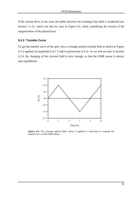
To get the transfer curve of the sp<strong>in</strong> valve, a triangle pulsed external field as shown <strong>in</strong> Figure<br />
6.5 is applied. Its amplitude is 0.1 T and its period time is 8 ns. As we will see later <strong>in</strong> Section<br />
6.2.4, the chang<strong>in</strong>g of the external field is slow enough, so that the GMR sensor is always<br />
near equilibrium.<br />
H z [T]<br />
0.15<br />
0.10<br />
0.05<br />
0.00<br />
-0.05<br />
-0.10<br />
-0.15<br />
0 2 4 6 8 10<br />
Time [ns]<br />
Figure 6.5: The external applied field, which is applied <strong>in</strong> z-direction to evaluate the<br />
transfer curve of the GMR sensor.<br />
70


