2 What is an fault arc - Die BG ETEM
2 What is an fault arc - Die BG ETEM
2 What is an fault arc - Die BG ETEM

You also want an ePaper? Increase the reach of your titles
YUMPU automatically turns print PDFs into web optimized ePapers that Google loves.
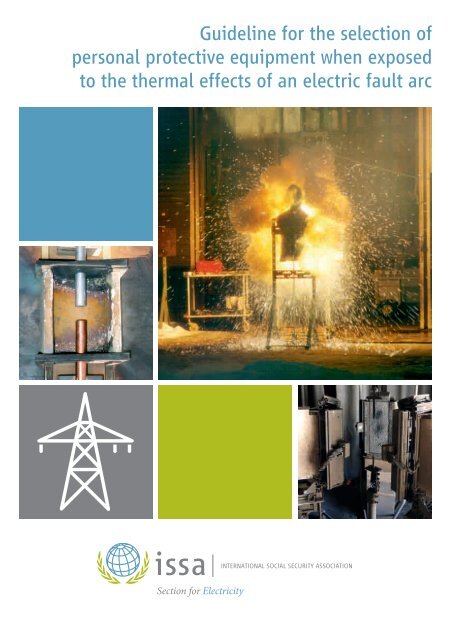
Guideline for the selection of<br />
personal protective equipment when exposed<br />
to the thermal effects of <strong>an</strong> electric <strong>fault</strong> <strong>arc</strong><br />
Section for Electricity
Th<strong>is</strong> edition of the guideline was elaborated by <strong>an</strong> international expert group:<br />
Holger Schau, TU Ilmenau, Germ<strong>an</strong>y – Convenor<br />
Jens Jühling, ISSA, Electricity Section, Germ<strong>an</strong>y<br />
Hendrik Beier, STFI, Germ<strong>an</strong>y<br />
Jaroslav Bek, PRE A.S., Czech Republic<br />
Mike Doherty, IHSA, C<strong>an</strong>ada<br />
Bogumil Dudek, EPC S.A., Pol<strong>an</strong>d<br />
Helmut Eichinger, DuPont, Geneva, Switzerl<strong>an</strong>d<br />
Jürgen Haase, Consulting Bureau Haase, Germ<strong>an</strong>y<br />
Angel Pérez Herr<strong>an</strong>z, UNESA, Spain<br />
Hugh Hoagl<strong>an</strong>d, ArcWear, USA<br />
Hocine Krizou, Hydro-Québec, C<strong>an</strong>ada<br />
Nicole Lachm<strong>an</strong>n, ISSA, Electricity Section, Germ<strong>an</strong>y<br />
Helena Mäkinen, FIOH, Finl<strong>an</strong>d<br />
Martin Mehlem, <strong>BG</strong> <strong>ETEM</strong>, Germ<strong>an</strong>y<br />
Joshua D. Moody, Westex Inc., USA<br />
Paul Smith, ENA, UK<br />
H<strong>an</strong>s-Peter Steimel, <strong>BG</strong> <strong>ETEM</strong>, Germ<strong>an</strong>y<br />
Chr<strong>is</strong>ti<strong>an</strong> Troger, AUVA, Austria<br />
Dominique Vacher, EDF – DRVT, Fr<strong>an</strong>ce<br />
Zdenek Václavek, ČSZE, Czech Republic<br />
2nd Edition 2011<br />
ISBN 978-3-937824-08-6<br />
Editor:<br />
International Social Security Association<br />
Section for Electricity, Gas <strong>an</strong>d Water<br />
c/o Berufsgenossenschaft Energie Textil Elektro Medienerzeugn<strong>is</strong>se<br />
Gustav-Heinem<strong>an</strong>n-Ufer 130, D-50968 Köln, Germ<strong>an</strong>y<br />
All rights reserved. No part of th<strong>is</strong> book may be reprinted or reproduced<br />
or utilized in <strong>an</strong>y form or by <strong>an</strong>y electronic, mech<strong>an</strong>ical, or other me<strong>an</strong>s, now<br />
known or hereafter invented, including photocopying <strong>an</strong>d recording, or in <strong>an</strong>y<br />
information storage or retrieval system, without perm<strong>is</strong>sion in writing from<br />
the publ<strong>is</strong>hers.
Guideline<br />
for the selection of<br />
personal protective equipment<br />
when exposed to the thermal<br />
effects of <strong>an</strong> electric <strong>fault</strong> <strong>arc</strong>
Contents<br />
1 Scope – Introduction 7<br />
2 <strong>What</strong> <strong>is</strong> <strong>an</strong> <strong>fault</strong> <strong>arc</strong> – types of exposure 9<br />
3 Hazards of <strong>fault</strong> <strong>arc</strong>s 10<br />
3.1 Physical <strong>an</strong>d technical effects 10<br />
3.2 Effects on the hum<strong>an</strong> body 10<br />
4 Arc thermal r<strong>is</strong>k parameters <strong>an</strong>d their evaluation 13<br />
4.1 Essential <strong>arc</strong> parameters 13<br />
4.2 Calculation <strong>an</strong>d measurement of thermal r<strong>is</strong>k parameters 14<br />
5 St<strong>an</strong>dardized test procedures for PPE products against<br />
thermal <strong>arc</strong> hazards 15<br />
5.1 General 15<br />
5.2 Arc rating test IEC 61482-1-1 17<br />
5.3 Box test IEC 61482-1-2 19<br />
6 Textile material <strong>an</strong>d protective clothing 22<br />
6.1 Arc thermal protection requirements – IEC 61482-2 22<br />
6.2 Assessment parameters 23<br />
6.3 Flammability of fabrics 25<br />
6.4 Recommendations for specimen selection of material 25<br />
6.5 Quality assur<strong>an</strong>ce 26<br />
6.6 Recommendations for wearing <strong>an</strong>d cle<strong>an</strong>ing 27<br />
7 Other PPE products 29<br />
8 R<strong>is</strong>k assessment <strong>an</strong>d calculation of <strong>arc</strong> r<strong>is</strong>ks 31<br />
8.1 Selection of PPE <strong>an</strong>d PPE test method 31<br />
8.2 Incident energy determination for selecting ATPV 33<br />
8.3 Calculation of expected <strong>an</strong>d equivalent <strong>arc</strong> energy for<br />
selecting box test protection class 34<br />
8.4 Empirical relationship between ATPV <strong>an</strong>d box test<br />
protection class 36<br />
9 References 38<br />
5
Contents<br />
Annex 1: 40<br />
Determination of the electric <strong>arc</strong> power <strong>an</strong>d energy<br />
Annex 2: 43<br />
Arc thermal r<strong>is</strong>k parameters – definitions <strong>an</strong>d terms<br />
Annex 3: 47<br />
Test report on <strong>an</strong> <strong>arc</strong> rating test – Determination of the ATPV<br />
of <strong>an</strong> example fabric<br />
Annex 4: 49<br />
Test report on a box test – Determination of the protection class<br />
of <strong>an</strong> example fabric<br />
Annex 5: 53<br />
Arc testing of gloves <strong>an</strong>d face shields by me<strong>an</strong>s of the box test<br />
Annex 6: 57<br />
Arc r<strong>is</strong>k calculation algorithm for the selection of PPE tested<br />
according to the box test<br />
Annex 7: 65<br />
Matrix of work activities/power equipment <strong>an</strong>d PPE required<br />
L<strong>is</strong>t of symbols 67<br />
6
1 Scope – Introduction<br />
Each <strong>an</strong>d every day electro-technical work <strong>is</strong> carried out world-wide at the r<strong>is</strong>k of<br />
the occurrence of <strong>an</strong> electric <strong>fault</strong> <strong>arc</strong> either by failure or due to a technical reason.<br />
There are different ways to protect people against the <strong>arc</strong> r<strong>is</strong>ks. At first the <strong>fault</strong><br />
<strong>arc</strong> shall be prevented by technical measures such as constructions <strong>an</strong>d electrical<br />
protective devices, <strong>an</strong>d creating electrically safe working conditions (de-energized<br />
installations, working rules etc.). Training <strong>an</strong>d competence policy procedures have<br />
to be applied. In m<strong>an</strong>y case it <strong>is</strong> not possible to totally eliminate the r<strong>is</strong>k that nevertheless<br />
a <strong>fault</strong> <strong>arc</strong> c<strong>an</strong> occur <strong>an</strong>d Personal Protective Equipment (PPE) must be<br />
selected for protecting people.<br />
Since the first publication of these guidelines in 2001 great adv<strong>an</strong>ces have been<br />
made. The effects when <strong>an</strong> electric <strong>arc</strong> occurs c<strong>an</strong> now be specified with more<br />
prec<strong>is</strong>ion. We are now able to predict what <strong>arc</strong> energies have to be expected in the<br />
events of <strong>arc</strong>ing <strong>fault</strong>s. Moreover it <strong>is</strong> difficult in <strong>an</strong> electric installation to predict the<br />
direction of the <strong>arc</strong> due to the magnetic field caused by the short circuit current, <strong>an</strong>d<br />
the resulting movements of the <strong>arc</strong> plasma <strong>an</strong>d the <strong>arc</strong> roots at different elevations<br />
of the electric <strong>arc</strong>. But there <strong>is</strong> now <strong>an</strong> improved knowledge on these processes.<br />
However there are different consequences of electric <strong>fault</strong> <strong>arc</strong>s: thermal effects,<br />
electric shock, no<strong>is</strong>e, UV em<strong>is</strong>sions, pressure, shrapnel, the consequences of<br />
physical <strong>an</strong>d mental shock <strong>an</strong>d toxic influences. St<strong>an</strong>dards <strong>an</strong>d test methods<br />
deal only with the thermal effects. Th<strong>is</strong> guideline focus also only on these aspects<br />
representing the most serious r<strong>is</strong>ks for persons.<br />
Thus PPE that works one hundred per cent against <strong>an</strong> electric <strong>fault</strong> <strong>arc</strong> <strong>is</strong> not<br />
possible. Rather, the consequences of <strong>an</strong> electric <strong>arc</strong> c<strong>an</strong> be reduced <strong>an</strong>d m<strong>an</strong>y<br />
times eliminated.<br />
In the case that <strong>an</strong>y work in the vicinity of <strong>an</strong> electrical installation or under live<br />
conditions <strong>is</strong> necessary, the person <strong>is</strong> generally in <strong>an</strong> area that <strong>is</strong> not approachable<br />
for the normal population. In those cases the general technical preventive measures,<br />
e.g. plates <strong>an</strong>d doors, have to be opened or even to be removed for a certain period<br />
of time, as long as <strong>an</strong>y sort of aforesaid work has to be done. As these actions<br />
are part of mainten<strong>an</strong>ce <strong>an</strong>d repair work, hazards due to electric <strong>arc</strong>s c<strong>an</strong>not be<br />
completely eliminated for the fore-seeable future.<br />
Additionally other workers such as operators may be in proximity with the equipment<br />
or interact in such a way which could be exposed to <strong>an</strong> electrical <strong>arc</strong>. These r<strong>is</strong>ks<br />
should be included in the r<strong>is</strong>k assessment, too.<br />
In the frame of the International Section of the ISSA on Prevention of Occupational<br />
R<strong>is</strong>ks due to Electricity <strong>an</strong> international working group <strong>an</strong>alyzed the situation <strong>an</strong>d<br />
7
1 Scope – Introduktion<br />
provides new information. Th<strong>is</strong> rev<strong>is</strong>ed guideline reflects the improved knowledge<br />
since the first edition. A complete rev<strong>is</strong>ion was made.<br />
As major improvement the guideline gives information for r<strong>is</strong>k assessment <strong>an</strong>d how<br />
to apply the st<strong>an</strong>dardized procedures to the real work environment. The working<br />
group referred to experiences <strong>an</strong>d the improved situation of the st<strong>an</strong>dardization of<br />
electric <strong>arc</strong> test methods. Today considerations may be based on well-establ<strong>is</strong>hed<br />
testing methods for PPE for <strong>arc</strong> flash exposures that are internationally st<strong>an</strong>dardized<br />
<strong>an</strong>d harmonized.<br />
Th<strong>is</strong> guideline follows the requirements of the Europe<strong>an</strong> Directive for Personal<br />
Protective Equipment (89/686/EEC) [1]. In the following according PPE are considered<br />
exclusively; all items of th<strong>is</strong> guideline are PPE in the sense of the directive.<br />
The document <strong>is</strong> intend to help employers to fulfil the obligations according to<br />
the Council Directive 89/391/EEC on the introduction of measures to encourage<br />
improvements in the safety <strong>an</strong>d health of workers at work.<br />
8
2 <strong>What</strong> <strong>is</strong> <strong>an</strong> <strong>fault</strong> <strong>arc</strong> – types of exposure<br />
An electric <strong>arc</strong> <strong>is</strong> <strong>an</strong> self-maintaining d<strong>is</strong>charge in gases. It originates from gas ionization<br />
<strong>an</strong>d <strong>is</strong> a conductive electrical interconnection between electrodes of different<br />
potentials, different phase relationship or one of these <strong>an</strong>d earth. An electric <strong>fault</strong> <strong>arc</strong><br />
in electrical power equipment <strong>is</strong> <strong>an</strong> unintended event. It c<strong>an</strong> be caused by a technical<br />
<strong>fault</strong> or – as it <strong>is</strong> documented in most cases – by m<strong>is</strong>take of the operator. Fault <strong>arc</strong>s<br />
accomp<strong>an</strong>y almost all short-circuits in electric power equipment with releasing huge<br />
amounts of energy.<br />
Electric <strong>arc</strong>s do not only occur with short-circuits but also in case of switching-off<br />
or breaking electrical circuits under load (fuses, d<strong>is</strong>connectors, cables, cable lugs,<br />
terminal ends) if there are no special precautions. These switching <strong>arc</strong>s may also<br />
be of r<strong>is</strong>k for persons <strong>an</strong>d cause electric <strong>fault</strong> <strong>arc</strong>s. But the highest energies are<br />
released in case of short-circuit <strong>fault</strong> <strong>arc</strong>s.<br />
While in the low voltage r<strong>an</strong>ge a galv<strong>an</strong>ic contact <strong>is</strong> necessary to ignite <strong>an</strong> electric<br />
<strong>fault</strong> <strong>arc</strong>, in high voltage systems only a non-compli<strong>an</strong>ce with a relev<strong>an</strong>t d<strong>is</strong>t<strong>an</strong>ce to<br />
live parts may be sufficient for triggering (electric breakdown or flashover).<br />
Fig. 2.1:<br />
Hot plasma <strong>an</strong>d gas cloud escaping in case<br />
of <strong>an</strong> <strong>arc</strong> in a box (enclosure), (source: Schau)<br />
In dependency of the system voltage level, power equipment construction <strong>an</strong>d<br />
working activity, different types of <strong>arc</strong>s <strong>an</strong>d exposure modes may ex<strong>is</strong>t:<br />
• open <strong>arc</strong> – <strong>arc</strong> in open installations, r<strong>is</strong>k of mainly radiation if a certain d<strong>is</strong>t<strong>an</strong>ce<br />
to the <strong>arc</strong> ex<strong>is</strong>ts<br />
• box <strong>arc</strong> – <strong>arc</strong> in a limited volume, focused <strong>an</strong>d amplified effects resulting from<br />
radiation, convection heat <strong>an</strong>d metal splash (see Fig. 2.1)<br />
• ejected <strong>arc</strong> – plasma jets are ejected <strong>an</strong>d affect persons<br />
• tracking <strong>arc</strong> – <strong>arc</strong>s formed at the body surface in connection with electrocution<br />
(current flow through hum<strong>an</strong> body) in HV systems.<br />
Due to extremely high energies occurring with <strong>fault</strong> <strong>arc</strong>s in case of short-circuits there<br />
are high r<strong>is</strong>ks for personal injury, damages of the equipment <strong>an</strong>d interruptions in the<br />
electric power supply.<br />
9
10<br />
3 Hazards of <strong>fault</strong> <strong>arc</strong>s<br />
3.1 Physical <strong>an</strong>d technical effects<br />
Depending on power <strong>an</strong>d duration of <strong>an</strong> electric <strong>arc</strong> quite different physical effects c<strong>an</strong><br />
ar<strong>is</strong>e which result from the extremely high temperature in the <strong>arc</strong> column. Temperatures<br />
of more th<strong>an</strong> 5.000° C are possible within <strong>an</strong> electric <strong>arc</strong>. In the <strong>arc</strong> development metal<br />
of the <strong>arc</strong> electrodes <strong>is</strong> vaporized <strong>an</strong>d ionized. It <strong>is</strong> formed into a conductive connection<br />
between the electrodes. Due to the intensified current flow the temperature r<strong>is</strong>es <strong>an</strong>d a<br />
plasma develops between the electrodes. Radiation <strong>is</strong> emitted by the <strong>arc</strong> plasma.<br />
A plasma <strong>is</strong> d<strong>is</strong>tingu<strong>is</strong>hed by the fact that all the chemical compounds in it have been<br />
broken up <strong>an</strong>d are ionized. Thus th<strong>is</strong> plasma cloud has got a very high chemical<br />
aggression. Due to the vaporization of metal <strong>an</strong>d the following immense heating<br />
up, a mass <strong>an</strong>d gas exp<strong>an</strong>sion takes place which rapidly tr<strong>an</strong>sports metallic vapor<br />
<strong>an</strong>d splash away from the <strong>arc</strong> roots. As a result of cooling down <strong>an</strong>d reacting with<br />
atmospheric oxygen, metal oxides c<strong>an</strong> be found which, in the course of further<br />
cooling, appear as black or grey smoke. As long as vapor <strong>an</strong>d smoke have got sufficient<br />
temperature they deposit a quite sticky sort of contamination (see Figure 3.1).<br />
An immediately physical reaction during the development of the <strong>arc</strong> <strong>is</strong> the huge<br />
pressure r<strong>is</strong>e which in 5–15 ms c<strong>an</strong> reach its first peak of up to 0,3 MPa. Th<strong>is</strong> corresponds<br />
to a pressure of 20–30 t/m 2 . If <strong>an</strong> unhindered pressure wave spreading<br />
c<strong>an</strong> not take place, one runs the r<strong>is</strong>k of destroying the electrical installation <strong>an</strong>d its<br />
surroundings mech<strong>an</strong>ically. Thus doors <strong>an</strong>d coverings c<strong>an</strong> be blown up, casings,<br />
compartments <strong>an</strong>d partitions c<strong>an</strong> burst <strong>an</strong>d break down.<br />
The optical radiation <strong>an</strong>d a convective heat tr<strong>an</strong>sfer of the flowing hot plasma <strong>an</strong>d<br />
gas, <strong>an</strong>d plasma jets occurring on the <strong>arc</strong> roots result in thermal exposures <strong>an</strong>d damages.<br />
Dependent on the intensity of the electric <strong>arc</strong>, the heat flux c<strong>an</strong> ignite nearby<br />
flammable materials. The molten metallic splashes which originate from the electric<br />
<strong>arc</strong> increase the fire hazard.<br />
3.2 Effects on the hum<strong>an</strong> body<br />
Due to the physical <strong>arc</strong> consequences described, according r<strong>is</strong>ks result for persons<br />
working at or in the vicinity of live parts, a direct exposure <strong>is</strong> likely because the equipment<br />
<strong>is</strong> opened for these working activities.<br />
The main hazards of personal injuries result from:<br />
• Pressure effects, forces on the body <strong>an</strong>d shrapnel due to the rapid heating-up<br />
of the <strong>arc</strong> surrounding gas
• Sound em<strong>is</strong>sion with acoustic stress<br />
• Electromagnetic, particularly high<br />
intensity optical radiation (v<strong>is</strong>ible light,<br />
ultra violet, infra-red) that <strong>is</strong> likely to<br />
cause irreversible damages of skin<br />
<strong>an</strong>d eyes<br />
• Extremely high thermal impacts due<br />
to the optical radiation <strong>an</strong>d the hot<br />
plasma cloud <strong>an</strong>d gas flow (heat flux)<br />
• Toxic gases <strong>an</strong>d hot particles caused<br />
by burning <strong>an</strong>d pyrolys<strong>is</strong> of surrounding<br />
materials (inclusively electrodes).<br />
By the sudden pressure r<strong>is</strong>e due to the<br />
striking of the electric <strong>arc</strong> detonation no<strong>is</strong>e<br />
results with sound pressure peak levels of<br />
eventually more th<strong>an</strong> 140 dB (un-weighted)<br />
which may lead to auditory damages to<br />
hum<strong>an</strong> beings.<br />
People working in the d<strong>an</strong>ger zone may<br />
be exposed to toxic degradation products<br />
originating from the electric <strong>arc</strong> with the<br />
consequence that, besides the harmful burn<br />
effects to the skin, there may also be serious<br />
lung damage due to inhalation.<br />
The main r<strong>is</strong>ks cons<strong>is</strong>t in the thermal hazards.<br />
High r<strong>is</strong>ks for personal injury result<br />
from the ignition of the garments <strong>an</strong>d other<br />
items worn by persons. Irrespective of the<br />
protective clothing a victim of <strong>an</strong> electric <strong>arc</strong><br />
has been wearing, there <strong>is</strong> <strong>an</strong>other aspect<br />
that <strong>is</strong> of interest to the development of<br />
preventive measures, namely the d<strong>is</strong>tribution<br />
of external surface burns. Thus the Institute<br />
for the Investigation of Electrical Accidents<br />
in Germ<strong>an</strong>y made a study of th<strong>is</strong> very topic.<br />
They evaluated severe electric <strong>arc</strong> accidents<br />
that had occurred in 1998 in Germ<strong>an</strong>y.<br />
Medical documents of 61 cases were available.<br />
The evaluation referred to thermal<br />
damage of the affected part of the body.<br />
3 Hazards of <strong>fault</strong> <strong>arc</strong>s<br />
Fig. 3.1: Installation after <strong>an</strong> electric <strong>arc</strong><br />
accident (source: Schau)<br />
< 10 %<br />
10 % - 30 %<br />
30 % - 40 %<br />
40 % - 60 %<br />
> 60 %<br />
67 %<br />
< 10 %<br />
50 %<br />
41 % 34 %<br />
Fig. 3.2: D<strong>is</strong>tribution of thermal injuries<br />
56 %<br />
11
3 Hazards of <strong>fault</strong> <strong>arc</strong>s<br />
Thermal damage included first or even higher degree burns. The results are sum -<br />
marized in the illustration (see Figure 3.2). It has to be emphasized that the most<br />
severely affected parts were the h<strong>an</strong>ds <strong>an</strong>d head including the neck; in more th<strong>an</strong> 2/3<br />
of the accidents the right h<strong>an</strong>d was injured <strong>an</strong>d in approximately half of the accidents<br />
the face <strong>an</strong>d neck regions were impacted. In addition, the forearms (41 % of the<br />
right <strong>an</strong>d 34 % of the left) were quite often injured. All other parts of the body were<br />
damaged up to a level of 10 %. However, very severe <strong>an</strong>d lethal consequences are<br />
likely particularly in case of large-area burns on the main body.<br />
12
4 Arc thermal r<strong>is</strong>k parameters <strong>an</strong>d their<br />
evaluation<br />
4.1 Essential <strong>arc</strong> parameters<br />
Direct <strong>an</strong>d indirect exposures resulting from <strong>fault</strong> <strong>arc</strong>s are mainly depend on the<br />
• electrical <strong>arc</strong> energy W<strong>arc</strong> = WLB<br />
• <strong>arc</strong> active power P<strong>arc</strong> = PLB<br />
• time duration of <strong>arc</strong>ing t<strong>arc</strong> = tk<br />
• d<strong>is</strong>t<strong>an</strong>ce to the <strong>arc</strong> a.<br />
The <strong>arc</strong> energy <strong>is</strong> a well defined measure <strong>an</strong>d rating of the specific conditions of<br />
the <strong>fault</strong> location. It <strong>is</strong> dependent on the electric power system parameters <strong>an</strong>d the<br />
construction of the electric power equipment.<br />
Regarding the thermal <strong>arc</strong> effects, furthermore, the energy density received at the<br />
surface affected <strong>is</strong> of import<strong>an</strong>ce. Th<strong>is</strong> <strong>is</strong> the incident energy Ei. It c<strong>an</strong> be a direct<br />
exposure incident energy EiO or, if it <strong>is</strong> considered on the back of PPE, a tr<strong>an</strong>smitted<br />
incident energy Eit.<br />
Following the most import<strong>an</strong>t r<strong>is</strong>k parameters are: <strong>arc</strong> power, <strong>arc</strong> energy, incident<br />
energy.<br />
The relationship between the incident energy <strong>an</strong>d the electric <strong>arc</strong> energy <strong>is</strong> very complex<br />
<strong>an</strong>d soph<strong>is</strong>ticated. There <strong>is</strong> in principle a proportionality, but the tr<strong>an</strong>sm<strong>is</strong>sion<br />
function fT <strong>is</strong> nonlinear:<br />
Ei = fT · W<strong>arc</strong> with fT = f (x1, x2, x3, x4, x5, x6).<br />
The main principle influences are<br />
x1 – d<strong>is</strong>t<strong>an</strong>ce a to the <strong>arc</strong> ax<strong>is</strong> (approximately inversely proportional to the square)<br />
x2 – <strong>arc</strong> space environment (open <strong>arc</strong>, box <strong>arc</strong>, walls, …)<br />
x3 – type of electrode configuration (vertical, horizontal, barriers, 2-phase/3-phase)<br />
x4 – electrodes gap d<br />
x5 – electrode material<br />
x6 – level of system voltage <strong>an</strong>d current.<br />
These factors determine what type of <strong>arc</strong> <strong>is</strong> formed <strong>an</strong>d represent the heat tr<strong>an</strong>sm<strong>is</strong>sion<br />
conditions.<br />
13
4 Arc thermal r<strong>is</strong>k parameters <strong>an</strong>d their evaluation<br />
Essential definitions <strong>an</strong>d terms are summarized in Annex 2.<br />
4.2 Calculation <strong>an</strong>d measurement of thermal r<strong>is</strong>k parameters<br />
In the st<strong>an</strong>dardized electric <strong>arc</strong> test methods copper calorimeters are used to measure<br />
the incident energy. The maximum value of the temperature r<strong>is</strong>e dTmax of the defined<br />
calorimeter copper d<strong>is</strong>c (delta peak temperature) <strong>is</strong> proportional to the incident<br />
energy Ei (see Figure 4.1):<br />
with<br />
14<br />
Ei =<br />
m . cp<br />
A<br />
. dTmax<br />
m – mass of calorimeter copper d<strong>is</strong>c<br />
A – cross sectional area of calorimeter copper d<strong>is</strong>c<br />
cp – specific heat capacity coefficient of copper<br />
dTmax – delta peak temperature (maximum temperature r<strong>is</strong>e) of the calorimeter.<br />
The delta peak temperature <strong>is</strong> the difference between the maximum temperature<br />
during the test exposure time of 30 s <strong>an</strong>d the initial temperature of the sensor.<br />
Fig. 4.1: Temperature r<strong>is</strong>e course during <strong>an</strong> <strong>arc</strong> test (example with sensor 1 directly exposed <strong>an</strong>d<br />
sensor 2 behind PPE)
5 St<strong>an</strong>dardized test procedures for PPE<br />
products against thermal <strong>arc</strong> hazards<br />
5.1 General<br />
Necessary base for the assessment of PPE <strong>an</strong>d their selection for practical use are<br />
reproducible product tests. The PPE have to be tested for proving its res<strong>is</strong>t<strong>an</strong>ce as<br />
well as its protection effect (heat attenuation) against the thermal effects of electric<br />
<strong>fault</strong> <strong>arc</strong>s (see Fig. 5.1).<br />
PPE must meet these two requirements<br />
regarding <strong>arc</strong> flash r<strong>is</strong>ks. In<br />
the past the considerations <strong>an</strong>d tests<br />
were only focussed on flame res<strong>is</strong>t<strong>an</strong>ce<br />
<strong>an</strong>d proving PPE to do not<br />
aggravate the <strong>arc</strong> consequences. To<br />
be flame retard<strong>an</strong>t, <strong>is</strong> a very import<strong>an</strong>t<br />
base for PPE but not sufficient.<br />
PPE components such as textiles<br />
of garment <strong>an</strong>d clothing, gloves <strong>an</strong>d<br />
v<strong>is</strong>ors must also limit the incident energy<br />
to a non-d<strong>an</strong>gerous degree. According<br />
tests of products as<br />
well as systems are necessary with<br />
measuring the incident energy.<br />
Today there are 2 different test methods<br />
st<strong>an</strong>dardized for testing of textile<br />
material <strong>an</strong>d clothing <strong>an</strong>d meeting the<br />
requirements mentioned above:<br />
Fig. 5.1: Test m<strong>an</strong>nequin with a jacket<br />
exposed to <strong>an</strong> <strong>arc</strong> in a box test<br />
• The Arc rating test according to IEC or EN 61482-1-1 [3] <strong>an</strong>d<br />
• The Box test according to IEC or EN 61482-1-2 [4].<br />
Both test methods use different test-set-ups, <strong>arc</strong> configurations <strong>an</strong>d types, test<br />
parameters, test procedures <strong>an</strong>d result parameters. The results c<strong>an</strong>not be neither<br />
physically compared nor mathematically tr<strong>an</strong>sformed into each other. PPE have to<br />
be tested <strong>an</strong>d assessed either to the one or the other method.<br />
15
5 St<strong>an</strong>dardized test procedures for PPE products against thermal <strong>arc</strong> hazards<br />
16<br />
IEC 61482-1-1 IEC 61482-1-2<br />
Set-up Long open <strong>arc</strong> Arc in a box<br />
Test energy Variable adjusted by <strong>arc</strong> const<strong>an</strong>t, two possible<br />
duration at const<strong>an</strong>t test levels (classes)<br />
current<br />
Heat tr<strong>an</strong>sfer All directions: Focussed:<br />
mainly radiation Radiation, convection,<br />
metal splash<br />
Test result Arc rating (ATPV or EBT50) Arc flash protection class: y/n<br />
Tab. 5.1: Specifics of the two st<strong>an</strong>dardized test procedures optionally to be used<br />
Import<strong>an</strong>t <strong>is</strong> that the test results are energy levels up to which the PPE shows <strong>arc</strong><br />
res<strong>is</strong>t<strong>an</strong>ce <strong>an</strong>d protection. In the past, both m<strong>an</strong>ufacturers <strong>an</strong>d users compared<br />
tested material or clothing <strong>an</strong>d considered the application very often only on the<br />
bas<strong>is</strong> of the prospective test current value (8 kA in case of ATPV testing, 4 or 7 kA<br />
respectively in box testing) without taking into consideration the other import<strong>an</strong>t<br />
set-up parameters determining energy levels (that me<strong>an</strong>s: exposure levels <strong>an</strong>d, thus<br />
protection levels).<br />
The test procedures of IEC 61482-1-1 (methods A <strong>an</strong>d B) [3] determine a qu<strong>an</strong>titative<br />
value characterizing the thermal protective perform<strong>an</strong>ce of the material or clothing:<br />
the Arc Thermal Perform<strong>an</strong>ce Value (ATPV) or the Break Open Energy (EBT50)<br />
respectively. The value (material property) makes it possible to compare different<br />
materials to each other. It <strong>is</strong> also possible to compare th<strong>is</strong> value to the predicted<br />
incident energy of <strong>an</strong> electric <strong>arc</strong> accident in <strong>an</strong>y particular working environment,<br />
based on the information gained by me<strong>an</strong>s of according procedures of the r<strong>is</strong>k<br />
assessment of that environment (e.g. IEEE 1585 or NFPA 70E, see chapter 8).<br />
Material or clothing tested by the box test method with const<strong>an</strong>t test parameters<br />
show protection at minimum up to the class energy level, the actual protection level<br />
may be higher. The test parameters are in general not the PPE application limits.<br />
Protection <strong>is</strong> almost given up to system currents <strong>an</strong>d voltages, <strong>arc</strong> durations <strong>an</strong>d<br />
exposure d<strong>is</strong>t<strong>an</strong>ces as long as the class energy level <strong>is</strong> not exceeded. The necessary<br />
<strong>arc</strong> flash class has to be selected on the base of a r<strong>is</strong>k <strong>an</strong>alys<strong>is</strong>. Other methods as<br />
mentioned above must be used because the according <strong>arc</strong> energy levels have to be<br />
found (see chapter 8).
5 St<strong>an</strong>dardized test procedures for PPE products against thermal <strong>arc</strong> hazards<br />
5.2 Arc rating test IEC 61482-1-1<br />
How the test works<br />
The test <strong>is</strong> performed on flame res<strong>is</strong>t<strong>an</strong>t<br />
fabrics intended for clothing used in protection<br />
against momentary electrical <strong>arc</strong> flashes. The<br />
test set-up cons<strong>is</strong>ts of two vertically positioned<br />
rod electrodes (stainless steel) with <strong>an</strong><br />
<strong>arc</strong> gap d of 300 mm, where the electric <strong>arc</strong><br />
<strong>is</strong> ignited. Three sample holder p<strong>an</strong>els are<br />
positioned at a d<strong>is</strong>t<strong>an</strong>ce of 300 mm from the<br />
longitudinal ax<strong>is</strong> of the electrodes, spaced at<br />
120° from each other. Each sample holder<br />
has a minimum dimension of 550 mm x 200<br />
mm (height x width) <strong>an</strong>d <strong>is</strong> equipped with two<br />
calorimeters made of electrical grade copper.<br />
The test set-up provides <strong>an</strong> uninterrupted<br />
formation <strong>an</strong>d propagation of the <strong>arc</strong> in all<br />
directions (see Figure 5.2).<br />
Before testing, the test specimens are<br />
washed 5 times in accord<strong>an</strong>ce with ISO 6330,<br />
method 2A, <strong>an</strong>d drying by procedure E<br />
(tumble drying) unless otherw<strong>is</strong>e specified<br />
in the care labelling.<br />
Fig. 5.2: Set-up of the <strong>arc</strong> rating test<br />
(with electrode configuration, sample holders<br />
The materials are fastened to each of the <strong>an</strong>d calorimeter sensors around it)<br />
three vertical sample holders, enabling the<br />
simult<strong>an</strong>eous testing of three samples during each <strong>arc</strong> shot. The calorimeters behind<br />
the fabric samples measure the temperature r<strong>is</strong>e <strong>an</strong>d thus the heat flux tr<strong>an</strong>smitted<br />
through the sample. At the same time additional calorimeters, placed beside each<br />
sample holder, serve the purpose of measuring the total incident energy. Software<br />
<strong>is</strong> used for the acqu<strong>is</strong>ition of all of th<strong>is</strong> temperature data, for a period of 30 s after<br />
ignition of the <strong>arc</strong>.<br />
The test method prescribes a minimum of 20 data points for stat<strong>is</strong>tical signific<strong>an</strong>ce,<br />
<strong>an</strong>d since each test generates three data points, th<strong>is</strong> tr<strong>an</strong>slates to a requirement of<br />
at least 7 electric <strong>arc</strong> shots to be performed for each test series. The incident energy<br />
level <strong>is</strong> varied by adjusting the <strong>arc</strong> duration (combustion period of the <strong>arc</strong>), while the<br />
test current level (prospective current) <strong>is</strong> held at 8 kA. The variation of the <strong>arc</strong> duration<br />
directly affects incident energy. The incident energies of the test exposures should<br />
result in a d<strong>is</strong>tribution of recorded heat r<strong>is</strong>es both above <strong>an</strong>d below the Stoll curve.<br />
17
5 St<strong>an</strong>dardized test procedures for PPE products against thermal <strong>arc</strong> hazards<br />
The electric supply voltage should be sufficient to allow for the d<strong>is</strong>charge of <strong>an</strong><br />
electric <strong>arc</strong> with a gap of up to 305 mm. In practice th<strong>is</strong> corresponds to a mid-voltage<br />
source (e.g. around 3 kV AC). Th<strong>is</strong> source voltage guar<strong>an</strong>tees ignition <strong>an</strong>d stability<br />
of the <strong>arc</strong> throughout the whole test period.<br />
<strong>What</strong> the test measures<br />
Th<strong>is</strong> method utilizes a log<strong>is</strong>tic regression model to determine the <strong>arc</strong> rating of<br />
materials for clothing. Th<strong>is</strong> <strong>arc</strong> rating (either ATPV or EBT50) <strong>is</strong> expressed in kJ/m 2<br />
(or cal/cm 2 ). The Arc Thermal Perform<strong>an</strong>ce Value (ATPV) of a material <strong>is</strong> the incident<br />
energy on a material or a multilayer system of materials that results in a 50 %<br />
probability that sufficient heat tr<strong>an</strong>sfer through the tested specimen <strong>is</strong> predicted to<br />
cause the onset of a second degree skin burn injury based on the Stoll curve, without<br />
breakopen. Annex 3 shows <strong>an</strong> example test report.<br />
When a material or material system exhibits physical holes or openings during<br />
testing, either to expose the p<strong>an</strong>el or a non-flame res<strong>is</strong>t<strong>an</strong>t underlayer, th<strong>is</strong> <strong>is</strong> called<br />
break-open. If break-open <strong>is</strong> observed during testing, a breakopen <strong>an</strong>alys<strong>is</strong> will be<br />
performed utilizing log<strong>is</strong>itic regression in the same m<strong>an</strong>ner as ATPV <strong>an</strong>alys<strong>is</strong>. If the<br />
50 % ch<strong>an</strong>ce of material breakopen (EBT50) occurs at a lower energy level th<strong>an</strong> the<br />
ATPV, then the EBT50 must be reported as the <strong>arc</strong> rating.<br />
Additionally, the test measures the Heat Attenuation Factor (or HAF). HAF <strong>is</strong> a measurement<br />
of the percent energy that <strong>is</strong> blocked by the material or material system.<br />
How the test results c<strong>an</strong> be used<br />
The test procedure measures heat flux through test materials <strong>an</strong>d thus enables<br />
<strong>an</strong> easy material compar<strong>is</strong>on. Arc ratings c<strong>an</strong> be used to ass<strong>is</strong>t in the selection of<br />
appropriate protective clothing, in accord<strong>an</strong>ce with the r<strong>is</strong>k assessment.<br />
18
5.3 Box test IEC 61482-1-2<br />
How the test works<br />
5 St<strong>an</strong>dardized test procedures for PPE products against thermal <strong>arc</strong> hazards<br />
In the box test [4] <strong>arc</strong> res<strong>is</strong>t<strong>an</strong>ce <strong>an</strong>d protection are assessed for two different protection<br />
classes. An electric <strong>arc</strong> <strong>is</strong> fired in a 400 V AC test circuit, burning between two<br />
vertically arr<strong>an</strong>ged electrodes which are surrounded by a special test box made of<br />
plaster (Fig. 5.3).<br />
Fig. 5.3: Box test set-up for textile material testing of protective clothing: schematically (left) <strong>an</strong>d in the<br />
test lab (right, reverse <strong>an</strong>gle)<br />
<strong>What</strong> the test measures<br />
The <strong>arc</strong> flash classes are characterized by different levels of the electric <strong>arc</strong> energy,<br />
<strong>an</strong>d the incident energy resulting. Tab. 2 gives <strong>an</strong> overview. The incident energy <strong>is</strong><br />
the exposure level resulting at a d<strong>is</strong>t<strong>an</strong>ce a = 300 mm to the perpendicular <strong>arc</strong> ax<strong>is</strong>.<br />
Two calorimeters are used to measure the incident energy. Before a test series the<br />
direct exposure incident energy Ei0 <strong>is</strong> measured without test sample in order to check<br />
the validity of the test conditions. During the test series the calorimeters measure the<br />
tr<strong>an</strong>smitted incident energy Eit behind of the samples.<br />
W<strong>arc</strong>P = WLBP in kJ Eio in kJ/m²<br />
Class 1 158 135<br />
Class 2 318 423<br />
Tab. 5.2: Arc flash protection class test energy levels<br />
19
5 St<strong>an</strong>dardized test procedures for PPE products against thermal <strong>arc</strong> hazards<br />
Tests are d<strong>is</strong>tingu<strong>is</strong>hed for product assessment <strong>an</strong>d certificating material <strong>an</strong>d<br />
garment/clothing.<br />
The material box test method <strong>is</strong> used to measure <strong>an</strong>d find material response to <strong>an</strong><br />
<strong>arc</strong> exposure when tested in a flat configuration. A qu<strong>an</strong>titative measurement of the<br />
<strong>arc</strong> thermal perform<strong>an</strong>ce <strong>is</strong> made by me<strong>an</strong>s of the energy Eit tr<strong>an</strong>smitted through<br />
the material. The tests are assessed by me<strong>an</strong>s of the criteria of Tab. 5.3.<br />
20<br />
Parameter Criterion<br />
Burning time ≤ 5 s<br />
Melting No melting through to the inner side<br />
Hole No hole bigger th<strong>an</strong> max. 5 mm in every direction<br />
formation (in the innermost layer)<br />
Heat flux All value pairs (Eit – tmax) of the two calorimeters for a 4 of 5<br />
tests series are below corresponding STOLL limit<br />
Tab. 5.3: Test accept<strong>an</strong>ce criteria<br />
Final result of testing <strong>is</strong> the categorization to the protection classes (prove of passing<br />
test class conditions), me<strong>an</strong>ing the test proves if protection class 1 or 2 according<br />
to the corresponding test class conditions <strong>is</strong> achieved. The test <strong>is</strong> considered as<br />
passed, if all of the criteria according to Table 3 are met. Within one test, four valid<br />
<strong>arc</strong> shots are made under unch<strong>an</strong>ged conditions within a series of maximum 5 shots.<br />
Fig. 5.4 shows <strong>an</strong> example of material testing of a 2-layer system of <strong>an</strong> fabric with a<br />
total area mass of 460 g/m 2 . The class 2 box test <strong>is</strong> passed. The full notified body test<br />
report of <strong>an</strong>other textile material example passed the class 1 test <strong>is</strong> shown in Annex<br />
4. It <strong>is</strong> the same fabric type tested also in <strong>an</strong> <strong>arc</strong> rating test those results are shown in<br />
Annex 3.<br />
The garment box test method <strong>is</strong> used to test the function of the protective clothing<br />
after <strong>an</strong> <strong>arc</strong> exposure including all the garment findings, sewing tread, fastenings <strong>an</strong>d<br />
other accessories, no heat flux will be measured. The materials of the garment must<br />
have passed successfully the material box test <strong>an</strong>d the garment must fulfil the criteria<br />
burning time, melting <strong>an</strong>d hole formation also according to Table 3. After exposure fasteners<br />
shall be functional. Accessories shall have no negative influence to the results<br />
of the burning time, melting <strong>an</strong>d hole formation. The incident energy <strong>is</strong> not measured<br />
because of the influence of the design of the garment (e.g. pockets, flaps etc).
5 St<strong>an</strong>dardized test procedures for PPE products against thermal <strong>arc</strong> hazards<br />
How the test results c<strong>an</strong> be used<br />
PPE <strong>arc</strong> flash protection class (or test class) necessary has to be found by r<strong>is</strong>k<br />
assessment. The <strong>arc</strong> energy expected <strong>an</strong>d the <strong>arc</strong> energy protection level have to<br />
be determined for the specific working environment (see Par. 9).<br />
In the box test PPE <strong>is</strong> exposed, in addition to radiation, also to convective heat<br />
(plasma <strong>an</strong>d gas cloud) <strong>an</strong>d metal splash (electrodes being of aluminium <strong>an</strong>d<br />
copper). Thus, PPE tested protects also against these dynamic <strong>an</strong>d thermal consequences<br />
at the according energy level.<br />
Fig. 5.4: Result of a<br />
class 2 box test of a<br />
2-layer textile material<br />
system (above) <strong>an</strong>d<br />
test sample before<br />
testing (below left)<br />
<strong>an</strong>d after <strong>arc</strong> exposure<br />
(below right)<br />
21
22<br />
6 Textile material <strong>an</strong>d protective clothing<br />
6.1 Arc thermal protection requirements – IEC 61482-2<br />
Electric <strong>fault</strong> <strong>arc</strong>s are of general r<strong>is</strong>k for workers. An electric <strong>fault</strong> <strong>arc</strong> c<strong>an</strong> particularly<br />
occur in case of electrotechnical work at or near to live parts. Protective clothing<br />
according to IEC 61482-2 [5] reduces the thermal <strong>arc</strong> hazards of electric <strong>fault</strong> <strong>arc</strong>s<br />
<strong>an</strong>d contributes to the protection of workers against these r<strong>is</strong>ks.<br />
The product st<strong>an</strong>dard IEC 61482-2 specifies requirements <strong>an</strong>d test methods applicable<br />
to materials <strong>an</strong>d garments for protective clothing for electrical workers against<br />
the thermal hazards of <strong>an</strong> electric <strong>arc</strong> based on<br />
• relev<strong>an</strong>t general properties of the textiles, tested with selected textile test<br />
methods, <strong>an</strong>d<br />
• <strong>arc</strong> thermal res<strong>is</strong>t<strong>an</strong>ce properties, such as<br />
- the <strong>arc</strong> rating of materials according to IEC 61482-1-1, or<br />
- the <strong>arc</strong> flash protection class of materials <strong>an</strong>d garments (Class 1 or Class 2)<br />
according to IEC 61482-1-2.<br />
Requirements do not address electric shock hazards, the present st<strong>an</strong>dard <strong>is</strong> applicable<br />
in combination with st<strong>an</strong>dards covering such hazards. The st<strong>an</strong>dard does not<br />
contain requirements for the protection of head, h<strong>an</strong>ds <strong>an</strong>d feet.<br />
Textile material <strong>an</strong>d clothing according to the product st<strong>an</strong>dard IEC 61482-2 <strong>is</strong><br />
tested by using a real electric <strong>arc</strong> as sources of thermal effects. The hot plasma<br />
<strong>an</strong>d gases in <strong>an</strong>d around the <strong>arc</strong> column are the source of the heat flux <strong>an</strong>d, consequently,<br />
the thermal effects. Details about heat tr<strong>an</strong>sfer <strong>an</strong>d test set-up according<br />
to IEC 61482-1-1 <strong>an</strong>d IEC 61482-1-2 are given in chapter 5.<br />
The st<strong>an</strong>dard IEC 61482-2 covers protective clothing against thermal <strong>arc</strong> hazards in<br />
general, not for a limited voltage level or r<strong>an</strong>ge only, although the test methods use<br />
set-ups with a defined test voltage. The mode <strong>an</strong>d violence of heat tr<strong>an</strong>sfer <strong>is</strong> only<br />
less specific for <strong>arc</strong>s burning in a LV circuit or in a MV <strong>an</strong>d HV one. Electric power<br />
<strong>an</strong>d <strong>arc</strong> duration are the primary influencing parameters <strong>an</strong>d characterize the thermal<br />
source. Clothing withst<strong>an</strong>ding the incident energy levels of the tests will have the<br />
according <strong>arc</strong> thermal protection effect in a LV or a MV/HV installation as well.
6.2 Assessment parameters<br />
6 Textile material <strong>an</strong>d protective clothing<br />
Flame res<strong>is</strong>t<strong>an</strong>ce <strong>an</strong>d flame spread<br />
Garments intend to protect against the thermal r<strong>is</strong>k of <strong>an</strong> electric <strong>arc</strong> shall not<br />
aggravate the r<strong>is</strong>k by ignition. Therefore all fabrics claiming compli<strong>an</strong>ce with the IEC<br />
61482-2 shall achieve a specified limited flame spread index when tested in accord<strong>an</strong>ce<br />
with ISO 15025 Procedure A <strong>an</strong>d classified according to ISO 14116. Hereby<br />
it <strong>is</strong> guar<strong>an</strong>teed that by a 10 s direct flame contact the material does not show flaming<br />
debr<strong>is</strong> <strong>an</strong>d the lowest boundary of <strong>an</strong>y flame does not reach the upper or vertical<br />
edge of the sample. Also the spread of a possible afterglow in the undamaged area <strong>is</strong><br />
excluded.<br />
If a single-layer material <strong>is</strong> used in the garment, th<strong>is</strong> material shall fulfil the limited<br />
flame spread index 3. Additionally to the requirements above th<strong>is</strong> me<strong>an</strong>s the preclusion<br />
of hole formation <strong>an</strong>d no afterflame time > 2 s.<br />
If a multi-layer material <strong>is</strong> used in the garment, the following requirements shall be<br />
fulfilled:<br />
- all outer layer <strong>an</strong>d innermost layer materials shall fulfil the limited flame spread<br />
index 3,<br />
- all middle layers shall fulfil in minimum the flame spread index 1.<br />
Also the main seams of the garment shall offer a suitable flame retard<strong>an</strong>t behaviour.<br />
Therefore the sewing thread used for these seams shall be tested according to ISO<br />
17493 with the temperature of 260 °C. Furthermore neither accessories nor closures<br />
used in the garment shall contribute to the severity of the injuries to the wearer in the<br />
event of a momentary electric <strong>arc</strong>. Generally, all parts of a garment shall be made of<br />
<strong>arc</strong> thermal res<strong>is</strong>t<strong>an</strong>t materials.<br />
Tear res<strong>is</strong>t<strong>an</strong>ce <strong>an</strong>d dimensional ch<strong>an</strong>ge<br />
Besides the flame retard<strong>an</strong>t behaviour of the materials, requirements for general<br />
properties of the textiles are of relev<strong>an</strong>ce for the user for safety <strong>an</strong>d durability reasons.<br />
Therefore the st<strong>an</strong>dard defines minimum requirements for the outer materials<br />
used in the garment.<br />
The outer fabrics shall have a tear res<strong>is</strong>t<strong>an</strong>ce of at least 15 N (for weight higher th<strong>an</strong><br />
220 g/m²) or at least 10 N (for weight within 150 g/m² <strong>an</strong>d 220 g/m²) tested according<br />
to ISO 13937-2. The tensile strength shall be at least 400 N (for weight higher th<strong>an</strong><br />
220 g/m²) or at least 250 N (for weight within 150 g/m² <strong>an</strong>d 220 g/m²) tested according<br />
to ISO 13934-1. If the garment <strong>is</strong> made of knitted outer material, i.e. polo shirt<br />
or pullover, these test methods are not applicable. In such a case the burst strength<br />
according to ISO 13938-1 shall be determined <strong>an</strong>d shall be of at least 200 kPa.<br />
23
6 Textile material <strong>an</strong>d protective clothing<br />
To guar<strong>an</strong>tee <strong>an</strong> appropriate usability after the care procedure defined by the<br />
m<strong>an</strong>ufacturer also the dimensional stability of the outer material <strong>is</strong> specified. When<br />
tested in accord<strong>an</strong>ce with ISO 5077 the woven outer material shall have a dimensional<br />
ch<strong>an</strong>ge not exceeding ± 3 % in the machine <strong>an</strong>d the cross directions. For<br />
knitted material the requirement <strong>is</strong> ± 5 % as maximum.<br />
Arc thermal res<strong>is</strong>t<strong>an</strong>ce<br />
Because the protective clothing covered by IEC 61482-2 shall have certain res<strong>is</strong>t<strong>an</strong>ce<br />
properties to the thermal effects of <strong>an</strong> electric <strong>arc</strong> the most import<strong>an</strong>t material<br />
parameter <strong>is</strong> the <strong>arc</strong> thermal res<strong>is</strong>t<strong>an</strong>ce. The two international test methods mentioned<br />
in chapter 5 shall provide information on the res<strong>is</strong>t<strong>an</strong>ce of clothing to the<br />
thermal effects of electric <strong>arc</strong>s. Each method gives different information. To be in<br />
accord<strong>an</strong>ce with th<strong>is</strong> st<strong>an</strong>dard, a product shall be evaluated by using IEC 61482-1-1<br />
or/<strong>an</strong>d IEC 61482-1-2. Depending on the needs, the users will specify for one test<br />
method or the other. Material test as well as garment test shall be performed. For<br />
garment certification both the material <strong>an</strong>d garment shall fulfil the requirements.<br />
When tested according to IEC 61482-1-1, the protective clothing made of the<br />
tested material shall be assigned a corresponding ATPV of the material. A protective<br />
clothing will demonstrate a minimum <strong>arc</strong> thermal res<strong>is</strong>t<strong>an</strong>ce, if the ATPV <strong>is</strong> at least<br />
167.5 kJ/m² (4 cal/cm²). The higher <strong>is</strong> the ATPV value, the better <strong>is</strong> the thermal<br />
res<strong>is</strong>t<strong>an</strong>ce under higher incident <strong>arc</strong> energy (higher current value, longer exposure<br />
time). In case that no ATPV c<strong>an</strong> be determined, the EBT50 shall be determined <strong>an</strong>d<br />
assigned to the tested material. The minimum EBT50 demonstrated by the material<br />
shall be at least 167.5 kJ/m 2 (4 cal/cm²).<br />
When tested according to IEC 61482-1-2, the protective clothing made of the tested<br />
material shall be assigned a Class 1 or a Class 2 depending on the test conditions<br />
<strong>an</strong>d the resulting <strong>arc</strong> thermal protection. Protective clothing will demonstrate a<br />
minimum <strong>arc</strong> thermal protection, if it passes the Class 1 test. A Class 2 indicates<br />
a higher <strong>arc</strong> thermal res<strong>is</strong>t<strong>an</strong>ce by higher incident <strong>arc</strong> energy.<br />
Besides fabric related requirements, the IEC 61482-2 also regulates import<strong>an</strong>t<br />
safety relev<strong>an</strong>t aspects for the garment. Each garment designed to protect the upper<br />
part of the body shall have long sleeves <strong>an</strong>d no exposed external metal shall be<br />
permitted. A worker should have the full body protected.<br />
If due to comfort requirements the garment <strong>is</strong> produced of materials with different<br />
<strong>arc</strong> thermal res<strong>is</strong>t<strong>an</strong>ce perform<strong>an</strong>ce for the front <strong>an</strong>d back (rear or dorsum) the exact<br />
information shall be given where the weaker area <strong>is</strong> located. Th<strong>is</strong> c<strong>an</strong> be done by<br />
me<strong>an</strong>s of a drawing of the garment including dimensions <strong>an</strong>d warning indication in<br />
the instructions for use. But it must be emphas<strong>is</strong>ed that such garments shall fulfil<br />
at least the requirements of Class 1 according to IEC 61482-1-2 or a minimum ATPV<br />
24
6 Textile material <strong>an</strong>d protective clothing<br />
rating of 167.5 kJ/m² (4 cal/cm²) according to IEC 61482-1-1 at all areas. The front<br />
side of the garment <strong>an</strong>d the complete sleeves (all around the arms <strong>an</strong>d over the complete<br />
length of the arms) of the garment shall fulfil the same <strong>arc</strong> thermal res<strong>is</strong>t<strong>an</strong>ce<br />
requirements.<br />
However the end user has to consider that the use of the st<strong>an</strong>dard IEC 61482-2 <strong>is</strong><br />
not obligatory. Especially for Europe where the basic safety <strong>an</strong>d health requirements<br />
of the document Council Directive 89/686/EEC are relev<strong>an</strong>t for all kinds of PPE, the<br />
fulfilment of the st<strong>an</strong>dard does not automatically obtain the assumption of conformity<br />
with these requirements. Nevertheless until there <strong>is</strong> no alterative assessment available,<br />
the consideration of the requirements given in IEC 61482-2 has to be seen as<br />
best available option.<br />
6.3 Flammability of fabrics<br />
It must be emphas<strong>is</strong>ed that all fibres, either natural or synthetic, c<strong>an</strong> burn to some<br />
extent. Thus in st<strong>an</strong>dard<strong>is</strong>ation the term “flame-res<strong>is</strong>t<strong>an</strong>t” <strong>is</strong> used. The fabrics are<br />
especially character<strong>is</strong>ed by how they react after having been exposed to flames.<br />
The protective efficiency of a material lies in the fact that the user has to be insulated<br />
from the exposed heat energy <strong>an</strong>d that the material in the specific areas that start<br />
burning cease to do so as soon as possible (see after-flame time). Ultimately, the<br />
user should not be injured by the material used. However, the protective clothing<br />
c<strong>an</strong>not ‘guar<strong>an</strong>tee’ 100 % protection against exposure to a certain hazard.<br />
6.4 Recommendations for specimen selection of material<br />
If <strong>an</strong> electric <strong>arc</strong> hazard <strong>is</strong> at all possible at a workplace, work clothing of flameres<strong>is</strong>t<strong>an</strong>t<br />
material shall be used.<br />
As a result of a r<strong>is</strong>k <strong>an</strong>alys<strong>is</strong> (see chapter 8), <strong>an</strong>d a knowledge of the relative thermal<br />
perform<strong>an</strong>ces of various fabric systems according to one or the other test method described<br />
above, the appropriate level of protective clothing should be selected.<br />
As a minimum guideline, for workplaces with electric <strong>arc</strong> hazard the persons concerned<br />
shall wear protective clothing with <strong>an</strong> ATPV of at least 167.5 kJ/m² (4 cal/cm²)<br />
when tested according to IEC 61482-1-1 or with the protection level Class 1 of the<br />
IEC 61482-1-2 method (basic protection).<br />
For increased hazard situations a garment with higher ATPV or a Class 2 garment<br />
should be selected (increased protection).<br />
25
6 Textile material <strong>an</strong>d protective clothing<br />
If the incident energy to be expected <strong>is</strong> higher the clothing then <strong>is</strong> likely to be alone<br />
not sufficient to provide the necessary protection.<br />
It has to be emphas<strong>is</strong>ed that the tested materials do not res<strong>is</strong>t each <strong>an</strong>d every<br />
electric <strong>arc</strong>. An electric <strong>arc</strong> <strong>is</strong> <strong>an</strong> unexpected incident, the intensity of which c<strong>an</strong> only<br />
be estimated by network parameters. However, additional d<strong>an</strong>ger <strong>an</strong>d uncertainty<br />
ar<strong>is</strong>es by e.g. the d<strong>is</strong>t<strong>an</strong>ce the person concerned <strong>is</strong> st<strong>an</strong>ding away from the <strong>arc</strong>, its<br />
position etc. Generally, the necessary <strong>arc</strong> thermal protection perform<strong>an</strong>ce <strong>is</strong> to be<br />
determined by r<strong>is</strong>k <strong>an</strong>alys<strong>is</strong>. Guid<strong>an</strong>ce for the appropriate selection of <strong>an</strong> ATPV <strong>is</strong><br />
provided in other separate st<strong>an</strong>dards, e.g. in IEEE 1584 [6] <strong>an</strong>d NFPA 70E [7], or<br />
product information (e.g. [8]). For the selection of protective clothing tested according<br />
to IEC 61482-1-2 (box test) the future Germ<strong>an</strong> <strong>BG</strong>I guideline [9] (under preparation<br />
now) will offer practice-related ass<strong>is</strong>t<strong>an</strong>ce (see also Par. 8.3).<br />
Due to the enormous variety of available woven <strong>an</strong>d knitted fabrics, laminates<br />
<strong>an</strong>d their combinations as material assembly it <strong>is</strong> hard to define minimum material<br />
weights. Besides, especially for materials with increased protection perform<strong>an</strong>ce<br />
tests have always shown that the area weight of the material <strong>is</strong> not the only parameter<br />
of import<strong>an</strong>ce compared with the parameters’ set of <strong>an</strong> optimal fibres selection,<br />
fabric construction <strong>an</strong>d the arr<strong>an</strong>gement of the material assembly (see also 6.6).<br />
Therefore the chosen fabric systems shall be tested in order to measure their<br />
specific <strong>arc</strong> thermal perform<strong>an</strong>ce values.<br />
The r<strong>is</strong>k assessment may also be based on the determination of the <strong>arc</strong> energy <strong>an</strong>d<br />
<strong>arc</strong> incident energy to be expected in case of <strong>an</strong> <strong>arc</strong> <strong>fault</strong> in the installations where<br />
the clothing <strong>is</strong> intended to be worn while working.<br />
6.5 Quality assur<strong>an</strong>ce<br />
The protection effect of a textile fabric against the thermal r<strong>is</strong>ks of <strong>an</strong> electric <strong>arc</strong> depends<br />
on different parameters. Besides the most import<strong>an</strong>t flame-retard<strong>an</strong>t property<br />
also the fibre composition, the fabric construction <strong>an</strong>d the area mass are relev<strong>an</strong>t.<br />
As for each series production, deviations from the tested “master fabric” c<strong>an</strong> not be<br />
totally eliminated. Especially for natural fibres equipped with flame-retard<strong>an</strong>t properties<br />
the grade of flame-retard<strong>an</strong>t fabrics c<strong>an</strong> deviate from production to production.<br />
Fabrics which have passed the electric <strong>arc</strong> test may not pass if other fabrics of<br />
<strong>an</strong>other production are tested. Thus the production of flame-retard<strong>an</strong>t fabrics<br />
have to be tested shortly afterwards with regard to the fact whether flame-retard<strong>an</strong>t<br />
properties deteriorate or not.<br />
There <strong>is</strong> no real alternative test to the <strong>arc</strong> thermal res<strong>is</strong>t<strong>an</strong>ce test (destructive test)<br />
after completing the production phase for checking the conformity to the associated<br />
26
6 Textile material <strong>an</strong>d protective clothing<br />
requirement. Nevertheless both fabric m<strong>an</strong>ufacturer <strong>an</strong>d garment producer shall<br />
prove that they have followed the same documented m<strong>an</strong>ufacturing process <strong>an</strong>d<br />
assembly procedure as per the tested fabric <strong>an</strong>d garment.<br />
The m<strong>an</strong>ufacturers have to develop suitable r<strong>an</strong>dom sample tests for th<strong>is</strong> so that<br />
a const<strong>an</strong>t quality c<strong>an</strong> be guar<strong>an</strong>teed. Aging of the material which takes place in<br />
practice by use <strong>an</strong>d numerous launderings has to be taken into consideration, too.<br />
As a critical parameter for the protection perform<strong>an</strong>ce the limited flame spread shall<br />
be assessed <strong>an</strong>d documented by the material m<strong>an</strong>ufacturer for the lot size. The<br />
lot size <strong>is</strong>, as a minimum, the amount of material delivered to the garment m<strong>an</strong>ufacturer.<br />
As a minimum unit a roll of material should be considered.<br />
It shall be emphas<strong>is</strong>ed that there are very restrictive regulations for the production<br />
<strong>an</strong>d use of personal protective clothing in m<strong>an</strong>y countries. In the Europe<strong>an</strong> Community<br />
it <strong>is</strong> compulsory to do type tests for personal protective equipment before it c<strong>an</strong><br />
be placed on the market. PPE against electric <strong>arc</strong>s have to be seen as equipment of<br />
Category III according to PPE Directive 89/686/EEC. Therefore a quality assur<strong>an</strong>ce<br />
system or r<strong>an</strong>dom tests taken by a certified test laboratory <strong>is</strong> required in order to<br />
guar<strong>an</strong>tee the defined properties of the product during m<strong>an</strong>ufacturing.<br />
6.6 Recommendations for wearing <strong>an</strong>d cle<strong>an</strong>ing<br />
Protective clothing c<strong>an</strong> only be effective if it <strong>is</strong> used <strong>an</strong>d worn properly. When wearing<br />
protective clothing, all buttons or fasteners shall be closed, providing a barrier to<br />
the potential thermal hazard. Non-flame res<strong>is</strong>t<strong>an</strong>t undergarments worn should be<br />
constructed of natural fibre. Meltable synthetic non-flame res<strong>is</strong>t<strong>an</strong>t undergarments<br />
should not be allowed. Underwear melting under <strong>arc</strong> exposure may not be worn.<br />
Arc rated protective clothing shall cover all non-flame res<strong>is</strong>t<strong>an</strong>t clothing. Additionally,<br />
the outermost garment shall be flame res<strong>is</strong>t<strong>an</strong>t. Non-flame res<strong>is</strong>t<strong>an</strong>t garments (i.e.<br />
rainwear, jackets, cold weather garments, etc.) c<strong>an</strong> ignite in <strong>an</strong> electrical <strong>arc</strong> <strong>an</strong>d<br />
continue to burn, thus negating the protective capacity of the protective clothing worn<br />
underneath.<br />
Often, comfort <strong>an</strong>d ergonomic concerns are reasons cited for the inappropriate<br />
wearing of protective clothing. It <strong>is</strong> import<strong>an</strong>t that employees should be included<br />
in the process of selection <strong>an</strong>d trial wearing of the protective clothing before<br />
purchasing. Th<strong>is</strong> employee involvement has been found to be beneficial as to both<br />
the selection of appropriate protective clothing <strong>an</strong>d employee sat<strong>is</strong>faction.<br />
Not only the upper part of the body shall be protected by the clothing. Although none<br />
of the st<strong>an</strong>dards described before <strong>is</strong> directed to test trousers, <strong>an</strong> intensive evaluation<br />
of the protection perform<strong>an</strong>ce of these garments <strong>is</strong> necessary. For th<strong>is</strong> the use of<br />
27
6 Textile material <strong>an</strong>d protective clothing<br />
identical material for jacket <strong>an</strong>d trouser as well as the consideration of the design<br />
requirements given in IEC 61482-2 are essential. If as result of the r<strong>is</strong>k assessment<br />
of the workplace the use of protective clothing for the upper part of the body <strong>is</strong><br />
sufficient, the user has to guar<strong>an</strong>tee the suitability of the selected trouser by itself.<br />
To avoid resulting uncertainties <strong>an</strong>d possibly occurring r<strong>is</strong>ks, the selection of a<br />
complete suit of jacket <strong>an</strong>d trouser or a coverall <strong>is</strong> recommended.<br />
It c<strong>an</strong> be recommendable to protect the neck by using clothing with collar.<br />
Protective clothing <strong>an</strong>d other personal protective equipment should be inspected<br />
prior to use. These must be removed from service if found to be defective. The<br />
perform<strong>an</strong>ce of <strong>arc</strong> res<strong>is</strong>t<strong>an</strong>t protective clothing c<strong>an</strong> be reduced or negated by flammable<br />
contamin<strong>an</strong>ts. It <strong>is</strong> imperative to regularly cle<strong>an</strong> protective clothing to remove<br />
<strong>an</strong>y possible contamin<strong>an</strong>ts. Protective garments are labelled as to the recommended<br />
washing procedures. It <strong>is</strong> import<strong>an</strong>t to follow these recommendations to maintain the<br />
protective character<strong>is</strong>tics of the garment. Additionally, garments should be repaired<br />
with components that are at least equivalent to the original. Additional cle<strong>an</strong>ing <strong>an</strong>d<br />
repair information c<strong>an</strong> be obtained from the m<strong>an</strong>ufacturer.<br />
The Europe<strong>an</strong> Directive 89/686/EEC [1] requires that the m<strong>an</strong>ufacturer has to give<br />
product information for the user. The clothing shall be marked for example with the<br />
address of the m<strong>an</strong>ufacturer, number of st<strong>an</strong>dard, protection level, size of clothing,<br />
washing <strong>an</strong>d/or dry cle<strong>an</strong>ing procedure, comfort, ageing.<br />
Additionally each product has to be equipped with “relev<strong>an</strong>t information” for the customer<br />
in order to explain the kind of use, the level or classes mentioned, restrictions<br />
for use, warnings <strong>an</strong>d information about storing, cle<strong>an</strong>ing, decontamination, repairing<br />
<strong>an</strong>d so on.<br />
As additional import<strong>an</strong>t information it shall be emphas<strong>is</strong>ed that the garment <strong>is</strong><br />
normally not <strong>an</strong> electrical <strong>is</strong>olated protective clothing, for inst<strong>an</strong>ce according to EN<br />
50286:1999. And the user has also to consider that the whole protection against the<br />
thermal r<strong>is</strong>ks of <strong>an</strong> electric <strong>arc</strong> requires, additional to a garment, suitable protective<br />
equipment for the head (face <strong>an</strong>d eye protection) as well as for the h<strong>an</strong>ds. These<br />
items shall be tested according to the present available methods following IEC<br />
61482-1-1 or IEC 61482-1-2, too.<br />
28
7 Other PPE products: gloves, face shields<br />
For other components of PPE, such as protective gloves, helmets, face shields or<br />
v<strong>is</strong>ors etc. so far there have not yet been requirements for products <strong>an</strong>d testing in<br />
international harmonized st<strong>an</strong>dards.<br />
Fig. 7.1: Set-up for glove testing with adapting the <strong>arc</strong><br />
rating test (source: Dehn+Söhne GmbH + Co. KG)<br />
The <strong>arc</strong> rating test as well as the box test method, in<br />
principle, enable tests of protective gloves <strong>an</strong>d helmet-v<strong>is</strong>or<br />
combinations. Modifications in the test setup<br />
(sample <strong>an</strong>d sensor arr<strong>an</strong>gement) are necessary.<br />
Fig. 7.1 shows <strong>an</strong> according set-up for the <strong>arc</strong> rating<br />
test of gloves as used. An ASTM st<strong>an</strong>dard draft has<br />
being d<strong>is</strong>cussed for some time but not yet edited<br />
[10]. The box test set-up modification for gloves, as<br />
also be used, <strong>is</strong> presented in Fig. 7.2.<br />
For testing face shields there <strong>is</strong> the ASTM st<strong>an</strong>dard<br />
F 2178 [11] which <strong>is</strong> also based on the <strong>arc</strong> rating<br />
test of IEC 61482-1-1, providing the ATPV. In<br />
Europe a comparable st<strong>an</strong>dard <strong>is</strong> sill m<strong>is</strong>sing up to<br />
Fig. 7.2: Box test set-up for glove<br />
testing with glove p<strong>an</strong>els equipped by<br />
calorimeters<br />
29
7 Other PPE products: gloves, face shields<br />
now. With the Test Principles GS ET-29 [12] a guide for testing <strong>an</strong>d certificating PPE<br />
was developed on the base of the box test in Germ<strong>an</strong>y. Me<strong>an</strong>while the principles<br />
were tr<strong>an</strong>sferred in the new Germ<strong>an</strong> st<strong>an</strong>dard draft E DIN 58118 [13] complementing<br />
the Europe<strong>an</strong> st<strong>an</strong>dard EN 166 [14].<br />
PPE shall be tested according to the international harmonized st<strong>an</strong>dards, that<br />
me<strong>an</strong>s either in adaption of the <strong>arc</strong> rating test or the box test. Then there <strong>is</strong> the great<br />
adv<strong>an</strong>tage that a complete protective equipment tested <strong>an</strong>d assessed according to<br />
equal principles becomes available.<br />
Annex 5 gives additional information <strong>an</strong>d examples of testing of gloves <strong>an</strong>d face<br />
shields by me<strong>an</strong>s of the box test method.<br />
30
8 R<strong>is</strong>k assessment <strong>an</strong>d calculation of <strong>arc</strong><br />
r<strong>is</strong>ks<br />
8.1 Selection of PPE <strong>an</strong>d PPE test method<br />
In general there <strong>is</strong> a Hier<strong>arc</strong>hy of Control to identify the actions which should be<br />
considered in order following <strong>an</strong>y generic r<strong>is</strong>k assessment (according to the general<br />
principles of prevention of EU Council Directive 89/391/EEC). The use of PPE <strong>is</strong> <strong>an</strong><br />
action at the end of th<strong>is</strong> hier<strong>arc</strong>hy of hazard control measures cons<strong>is</strong>ting in:<br />
1. Eliminate: If the hazard <strong>is</strong> removed, all the other m<strong>an</strong>agement controls, such<br />
as assessment, record keeping, training, auditing are no longer needed.<br />
2. Substitute: If the hazard c<strong>an</strong>not be removed, substitute for a lower hazard.<br />
Th<strong>is</strong> may involve ch<strong>an</strong>ges in electrical system design, fuse rating, types of other<br />
protection devices etc.<br />
3. Reduce: Lower the exposure of the individual to the r<strong>is</strong>k by minimizing the time<br />
the worker <strong>is</strong> placed within a position of r<strong>is</strong>k.<br />
4. Adaptation: Where possible adapt work to the individual, taking account of the<br />
individual’s mental <strong>an</strong>d physical capabilities.<br />
5. Technical Progress: Take adv<strong>an</strong>tage of technical progress such as using remote<br />
operation of equipment, e.g. <strong>fault</strong> re-energizing devices, remote operation<br />
of switchgear/<strong>is</strong>olators etc.<br />
6. Isolation: Place a barrier between the individual <strong>an</strong>d the r<strong>is</strong>k exposure either<br />
through physical me<strong>an</strong>s (screens/operation from separate control room) or by<br />
d<strong>is</strong>t<strong>an</strong>ce between the individual <strong>an</strong>d the r<strong>is</strong>k environment.<br />
7. Multiple controls: Th<strong>is</strong> may utilize multiple methods of controls such as those<br />
technical <strong>an</strong>d procedural controls identified above. Layering of controls will<br />
enh<strong>an</strong>ce the level of mitigation of r<strong>is</strong>k to the individual if implemented correctly.<br />
8. Mainten<strong>an</strong>ce: Introduce/develop pl<strong>an</strong>ned mainten<strong>an</strong>ce <strong>an</strong>d inspection regimes<br />
for pl<strong>an</strong>t <strong>an</strong>d equipment to ensure correct operation of components <strong>an</strong>d<br />
elements such as switches, circuit breakers, <strong>is</strong>olators etc. Th<strong>is</strong> may involve the<br />
development/introduction of a r<strong>is</strong>k based mainten<strong>an</strong>ce program.<br />
9. Training: Ensure that all staff are aware of the r<strong>is</strong>ks of operating equipment,<br />
what actions to take to mitigate the r<strong>is</strong>k, are sufficiently competent to undertake<br />
31
8 R<strong>is</strong>k assessment <strong>an</strong>d calculation of <strong>arc</strong> r<strong>is</strong>ks<br />
32<br />
the work required <strong>an</strong>d underst<strong>an</strong>d fully how to implement <strong>an</strong>d use effectively<br />
safety st<strong>an</strong>dards/policies <strong>an</strong>d safety related equipment including PPE. It<br />
includes that employees have to know how to control their own PPE.<br />
10. Personal Protective Equipment: Th<strong>is</strong> should be used only as a me<strong>an</strong>s<br />
of last resort, after all other control measures have been considered <strong>an</strong>d or<br />
implemented. All PPE should be designed to appropriate st<strong>an</strong>dards <strong>an</strong>d be<br />
capable of protecting the individual from r<strong>is</strong>k of injury in reasonable circumst<strong>an</strong>ces.<br />
PPE should be worn, maintained, <strong>an</strong>d cle<strong>an</strong>ed in line with m<strong>an</strong>ufacturer’s<br />
instructions.<br />
11. Emergency arr<strong>an</strong>gements: Such as alarm systems <strong>an</strong>d back up controls.<br />
To be put in place when all else fails, th<strong>is</strong> should consider what action to take<br />
when <strong>an</strong> event occurs so that the effect of the event on the individual c<strong>an</strong> be<br />
minimized.<br />
In case of live working or working near to live parts PPE <strong>is</strong> required.<br />
The prov<strong>is</strong>ion of PPE by the employer, as well as its use by the employee, <strong>is</strong><br />
governed by national or international laws. Accordingly, the PPE provided must offer<br />
protection against the hazard being prevented without presenting <strong>an</strong> even greater<br />
hazard in itself. It must be suitable for the conditions present at the work place <strong>an</strong>d<br />
be appropriate to the ergonomic needs <strong>an</strong>d health requirements of the employees.<br />
Employees are required to properly use the personal protective equipment provided.<br />
As the result of the PPE test methods protection levels are determined in form of<br />
incident energies (<strong>arc</strong> rating) or electric <strong>arc</strong> energies (<strong>arc</strong> flash protection classes)<br />
where the PPE selection has to be based on. The applier of PPE <strong>is</strong> confronted with<br />
the necessity to consider <strong>an</strong>d h<strong>an</strong>dle these energy parameters. In order to provide<br />
support for th<strong>is</strong>, it was resolved to compile information in form of procedures,<br />
described afterwards. Principles of r<strong>is</strong>k <strong>an</strong>alys<strong>is</strong> <strong>an</strong>d <strong>arc</strong> flash studies are presented<br />
in the following.<br />
Corresponding to the two different <strong>arc</strong> test methods there are also separate ways of<br />
selecting PPE: PPE tested in<br />
• the <strong>arc</strong> rating test: <strong>is</strong> selected on the base of determining incident energies<br />
• the box test: <strong>is</strong> selected on the base of determining the electric <strong>arc</strong> energies<br />
to be expected in the work places under study. The methods for finding the expected<br />
values are tailored <strong>an</strong>d parameterized either to one or the other type of <strong>arc</strong> test <strong>an</strong>d<br />
its corresponding heat tr<strong>an</strong>sfer character<strong>is</strong>tics. Thus m<strong>is</strong>interpretation may result
8 R<strong>is</strong>k assessment <strong>an</strong>d calculation of <strong>arc</strong> r<strong>is</strong>ks<br />
from not paying attention of the correspondences, e.g. by using the incident energy<br />
determination to select PPE tested according to the box test.<br />
In 8.2 the procedures for selecting PPE of the <strong>arc</strong> rating test are presented. The<br />
method to be used in case of PPE classified by me<strong>an</strong>s of the box test <strong>is</strong> considered<br />
in 8.3.<br />
8.2 Incident energy determination methods for selecting ATPV<br />
Internationally recognized st<strong>an</strong>dards have been created to aid comp<strong>an</strong>ies in both<br />
determining the hazards associated with electrical <strong>arc</strong>s as well as choosing the<br />
appropriate personal protective equipment for the worker.<br />
NFPA 70E - St<strong>an</strong>dard for Electrical Safety in the Workplace<br />
NFPA 70E defines safe work practices for electrical workers. Within th<strong>is</strong> st<strong>an</strong>dard,<br />
methods of hazard r<strong>is</strong>k <strong>an</strong>alys<strong>is</strong> <strong>an</strong>d protection schemes are d<strong>is</strong>cussed. The st<strong>an</strong>dard<br />
requires that <strong>an</strong> <strong>arc</strong> flash hazard <strong>an</strong>alys<strong>is</strong> be performed for work on or near energized<br />
equipment. Th<strong>is</strong> <strong>an</strong>alys<strong>is</strong> will help to determine both the personal protective<br />
equipment needed as well as the <strong>arc</strong> flash protection boundary around the equipment<br />
where it should be worn.<br />
There are essentially three types of hazard r<strong>is</strong>k <strong>an</strong>alys<strong>is</strong> methods d<strong>is</strong>cussed.<br />
1. A detailed hazard r<strong>is</strong>k <strong>an</strong>alys<strong>is</strong> that calculates the available incident energy<br />
available as a result of <strong>an</strong> electrical <strong>arc</strong>. Th<strong>is</strong> method involves first determining<br />
the system, installation parameters <strong>an</strong>d modes of operation. Next the bolted <strong>fault</strong><br />
currents are calculated <strong>an</strong>d the corresponding <strong>arc</strong>ing currents are estimated.<br />
Note that the <strong>arc</strong>ing currents are highly dependent on the protective devices <strong>an</strong>d<br />
resulting duration of the <strong>arc</strong>. Using th<strong>is</strong> information, along with system voltages,<br />
equipment configurations <strong>an</strong>d working d<strong>is</strong>t<strong>an</strong>ces, the available incident energy<br />
(in cal/cm 2 ) <strong>is</strong> calculated. Calculation methods <strong>an</strong>d formulae are available in<br />
the NFPA 70E st<strong>an</strong>dard as well as in the IEEE 1584 Guide. Using the resulting<br />
calculated energies, the appropriate PPE <strong>is</strong> chosen to have <strong>arc</strong> ratings equal to<br />
or greater th<strong>an</strong> the calculated incident energy.<br />
2. Example job tasks are given in tabular form. The job tasks are org<strong>an</strong>ized by<br />
both the type of equipment <strong>an</strong>d the system voltage. The associated hazard r<strong>is</strong>k<br />
categories (HRC) are given for each task. The HRC level corresponds to minimum<br />
<strong>arc</strong> ratings of protective clothing that are appropriate to wear for the given task.<br />
Guid<strong>an</strong>ce <strong>is</strong> also given in additional tables for other personal protective equipment<br />
for the specific HRC.<br />
33
8 R<strong>is</strong>k assessment <strong>an</strong>d calculation of <strong>arc</strong> r<strong>is</strong>ks<br />
3. A simplified two-category approach based off the job task matrix where PPE <strong>is</strong><br />
chosen based off of system voltage levels only. With a few exceptions, HRC 2<br />
clothing <strong>is</strong> recommended for voltages under 1000 volts <strong>an</strong>d HRC 4 clothing <strong>is</strong><br />
recommended for job tasks above 1000 volts.<br />
It <strong>is</strong> import<strong>an</strong>t to note that the <strong>arc</strong> flash protection boundary must be determined for<br />
either option chosen above. Arc rated clothing <strong>is</strong> required when working within the<br />
<strong>arc</strong> flash protection boundary. Options 2 <strong>an</strong>d 3 are useful for comp<strong>an</strong>ies who have<br />
highly diverse electrical systems.<br />
IEEE 1584 – IEEE Guide for Performing Arc Flash Hazard Calculations<br />
Th<strong>is</strong> st<strong>an</strong>dard defines a methodology for performing a detailed <strong>arc</strong> flash hazard<br />
<strong>an</strong>alys<strong>is</strong>. Information <strong>is</strong> gathered about each piece of equipment within the electrical<br />
system, e.g. system voltage, <strong>fault</strong> currents, potential durations <strong>an</strong>d working d<strong>is</strong>t<strong>an</strong>ces.<br />
Calculations are made to determine both the potential incident energy<br />
(in cal/cm 2 ) <strong>an</strong>d the <strong>arc</strong> flash protection boundary.<br />
8.3 Calculation of expected <strong>an</strong>d equivalent <strong>arc</strong> energy for selecting<br />
box test protection class<br />
The selection of PPE or the box test class for its testing requires a r<strong>is</strong>k <strong>an</strong>alys<strong>is</strong><br />
in which the electric <strong>arc</strong> energy W<strong>arc</strong> to be expected in the work place(s) under<br />
consideration has to be determined as well as the equivalent <strong>arc</strong> energy Wprot<br />
characterizing the PPE protection level for the work activity conditions (see<br />
procedure scheme in Fig. 8.1).<br />
The <strong>arc</strong> energy W<strong>arc</strong> = WLB to be expected depends on the power system conditions,<br />
that me<strong>an</strong>s on the system short-circuit capacity Sk“ at the possible <strong>fault</strong> locations <strong>an</strong>d<br />
the short-circuit duration tK that <strong>is</strong> determined by the electrical protective devices<br />
(clearing time of the breakers, fuses or occasionally special protection devices) <strong>an</strong>d<br />
to be derived from the switching character<strong>is</strong>tics. Furthermore it <strong>is</strong> dependent upon<br />
the switchgear conditions characterized by the factor kP taking into account the kind<br />
of <strong>arc</strong> burning <strong>an</strong>d the <strong>fault</strong> place electrode geometry. Th<strong>is</strong> factor may approximately<br />
be determined by me<strong>an</strong>s of the <strong>arc</strong> voltage from Fig. A1 in Annex 1 <strong>an</strong>d [15]. For a<br />
rough estimation without considering the switchgear geometry the maximum values<br />
of the kP curves may be used. Furthermore the value r<strong>an</strong>ges also given in Fig. A1<br />
were found to be typically for usual power installation configurations <strong>an</strong>d may be<br />
used as approximate values, too. In both cases the practical problems in finding the<br />
geometry parameters are avoided at accuracy expenses.<br />
34
8 R<strong>is</strong>k assessment <strong>an</strong>d calculation of <strong>arc</strong> r<strong>is</strong>ks<br />
Fig. 8.1: Overview on parameters <strong>an</strong>d procedure for r<strong>is</strong>k <strong>an</strong>alys<strong>is</strong> in connection with box-tested PPE<br />
The largest <strong>arc</strong> energy level determined for the case under study has to be compared<br />
with the protection level Wprot (equivalent <strong>arc</strong> energy). The equivalent <strong>arc</strong> energy<br />
<strong>is</strong> that one where the protective effect of the PPE <strong>is</strong> still given for the according<br />
exposure d<strong>is</strong>t<strong>an</strong>ce a (see Tab. 8.1).<br />
Class Protection degree Test level W<strong>arc</strong>P Protection level Wprot<br />
1 Basic protection 158 kJ<br />
2 Increased protection 318 kJ<br />
Tab. 8.1: Protection levels of PPE tested according to the box test<br />
(1… 2,4) . a ( 300 mm)<br />
(1… 2,4) . ( a )<br />
The PPE test level W<strong>arc</strong>P = WLBP <strong>is</strong> valid for the heat tr<strong>an</strong>sm<strong>is</strong>sion conditions <strong>an</strong>d the<br />
exposure d<strong>is</strong>t<strong>an</strong>ce of a = 300 mm of the box test set-up. Following the equivalent <strong>arc</strong><br />
energy has to determined by<br />
Wprot = kT . a<br />
( )<br />
300 mm<br />
Working place<br />
Protective devices Electric System Power equipment<br />
tk UrN Sk" d a kT<br />
Normalized <strong>arc</strong> power kp<br />
Electric <strong>arc</strong> energy expected<br />
W<strong>arc</strong> = WLB<br />
2<br />
. W .<br />
<strong>arc</strong>P<br />
300 mm<br />
W<strong>arc</strong>P = WLBP<br />
W<strong>arc</strong>P <strong>is</strong> the test level <strong>arc</strong> energy according to Table 5.2. The factor kT takes into account<br />
the electric power installation, particularly the volume of the opened compartment<br />
where the <strong>arc</strong> <strong>is</strong> expected to burn. As a st<strong>an</strong>dard <strong>an</strong>d particularly for narrow<br />
constructions with side <strong>an</strong>d back walls <strong>an</strong>d low volume (house service boxes, d<strong>is</strong>tribution<br />
boards etc.) th<strong>is</strong> factor <strong>is</strong> kT = 1, for wider burning r<strong>an</strong>ges (e.g. mainly back<br />
PPE<br />
PPE test level<br />
Arc flash protection class<br />
Equivalent <strong>arc</strong> energy (protection level)<br />
Wprot<br />
2<br />
2<br />
. 158 kJ<br />
. 318 kJ<br />
35
8 R<strong>is</strong>k assessment <strong>an</strong>d calculation of <strong>arc</strong> r<strong>is</strong>ks<br />
walls) it may be assumed as 1.5 to 1.9, <strong>an</strong>d in case of open <strong>arc</strong>s as 2.4.<br />
Annex 6 contains a detailed instruction for the r<strong>is</strong>k <strong>an</strong>alys<strong>is</strong>. Furthermore practical<br />
examples are presented.<br />
A basic <strong>arc</strong> protection <strong>is</strong> generally necessary <strong>an</strong>d to be provided by the use of<br />
according PPE if there <strong>is</strong> <strong>an</strong>y r<strong>is</strong>k of <strong>an</strong> electric <strong>fault</strong> <strong>arc</strong> <strong>an</strong>d <strong>arc</strong> exposure in all the<br />
working activities (electro-technical work) <strong>an</strong>d working environment. In case that<br />
<strong>arc</strong>-r<strong>is</strong>ky working <strong>is</strong> more often <strong>an</strong>d/or often done at power equipment of higher rating<br />
<strong>an</strong> increase <strong>arc</strong> protection <strong>is</strong> necessary. The dec<strong>is</strong>ion for one or the other protective<br />
level has to be based on the <strong>arc</strong> energy compar<strong>is</strong>on.<br />
Annex 7 presents <strong>an</strong> overview on work activities in different L.V. electric control <strong>an</strong>d<br />
power equipment (Un = UrN ≤ 1000 V) with the references to PPE required.<br />
36<br />
Class 1<br />
Class 2<br />
a = 300 mm √ kP<br />
a = 300 mm √ kP<br />
. Un . I " k3p . tk<br />
(1… 2, 4) . 91 kJ<br />
. Un . I " k3p . tk<br />
(1… 2, 4) . 184 kJ<br />
Tab. 8.2: Minimum working d<strong>is</strong>t<strong>an</strong>ces (<strong>arc</strong> flash boundaries)<br />
On the other h<strong>an</strong>d, in case of special working activities <strong>an</strong>d extreme <strong>arc</strong> r<strong>is</strong>ks <strong>an</strong>d/or<br />
equipment rating the certain application must be considered <strong>an</strong>d a conclusion drawn<br />
if live working or working at opened equipment <strong>is</strong> permitted or not, or the PPE have<br />
to meet special requirements. If the increased protection level of PPE <strong>is</strong> exceeded,<br />
there are the following practical alternatives:<br />
• Reducing <strong>arc</strong> duration by using according protective devices<br />
(e.g. ultra-fast fuses, special <strong>arc</strong> detecting <strong>an</strong>d extingu<strong>is</strong>hing systems)<br />
• Instructing for keeping minimum working d<strong>is</strong>t<strong>an</strong>ces (see Tab. 8.2)<br />
• Testing PPE on higher energy levels<br />
• Permitting work live working activities.<br />
8.4 Empirical relationship between ATPV <strong>an</strong>d box test protection class<br />
The test methods according to IEC 61482-1-1 <strong>an</strong>d IEC 61482-1-2 differ totally in<br />
their principles <strong>an</strong>d technical character<strong>is</strong>tics. But there <strong>is</strong> a common point: the<br />
measurement of the incident energy by calorimeters <strong>an</strong>d its evaluation by me<strong>an</strong>s of<br />
the STOLL-CHIANTA criterion for second-degree skin burns [2].
8 R<strong>is</strong>k assessment <strong>an</strong>d calculation of <strong>arc</strong> r<strong>is</strong>ks<br />
There <strong>is</strong> no mathematical-physical tr<strong>an</strong>sformation of the results of the both test<br />
methods because of the technical differences in the procedures, but a correlation<br />
may be made empirically.<br />
A pure empirical correlation of test result was made with typical woven fabrics which<br />
were tested both, by box method <strong>an</strong>d ATPV one. Figure 8.2 shows the principal<br />
correlation found for typical <strong>arc</strong> protective fabrics made of Aramides <strong>an</strong>d FR Cotton.<br />
Generalizing it c<strong>an</strong> be pointed out that box test <strong>arc</strong> protection class 2 <strong>is</strong> often safely<br />
just given for ATPV > 30 cal/cm².<br />
Class 1 me<strong>an</strong>s about ATPV = 4…30 cal/cm². The r<strong>an</strong>ge between approximately<br />
24… 34 cal/cm² <strong>is</strong> a mix zone, where class 2 c<strong>an</strong> be passed or failed in dependency<br />
on the specific fabric properties. The box test classes cover each a wide ATPV r<strong>an</strong>ge.<br />
Fig. 8.2: Empirical relationship between ATPV <strong>an</strong>d the <strong>arc</strong> protection class for typical <strong>arc</strong> protective<br />
woven fabrics/fabric assemblies made of Aramides <strong>an</strong>d FR Cotton (based on [8] <strong>an</strong>d test results of<br />
Kinectrics, Toronto, <strong>an</strong>d STFI, Bonn)<br />
The information of Fig. 8.2 may not be used for characterization of a non-tested material<br />
or PPE product. These considerations are thought for giving a rough estimation<br />
but not for replacing according tests as well as practical dec<strong>is</strong>ions or PPE selection.<br />
If the actual characterization of a product <strong>is</strong> needed, the according test <strong>is</strong> necessary<br />
to be made.<br />
Different textile materials, of course, have in each case their own relationships<br />
of actual test results. The “generalization” of Fig. 8.2 <strong>is</strong> made for several textile<br />
materials only <strong>an</strong>d represents the knowledge of today. It <strong>is</strong> not tr<strong>an</strong>sferable to other<br />
PPE. In case of e.g. face shields quite different relationships will ex<strong>is</strong>t.<br />
37
38<br />
9 References<br />
[1] Europe<strong>an</strong> Directive 89/686/EEC – Directive of the Europe<strong>an</strong> Council for the<br />
harmonization of the regulations of the EU countries for Personal Protective<br />
Equipment (PPE directive)<br />
[2] STOLL, A.M.; CHIANTA, M.A.: Method <strong>an</strong>d Rating System for Evaluation of<br />
Thermal Protection, Aerospace Medicine, Vol. 40, 1968, pp. 1232-1238<br />
[3] IEC 61482-1-1:2009: Live working – Protective clothing against the thermal<br />
hazards of <strong>an</strong> electric <strong>arc</strong> – Part 1 Test methods, Part 1-1 Determination of the<br />
<strong>arc</strong> rating (ATPV or EBT50) of flame-res<strong>is</strong>t<strong>an</strong>t textile materials. (publ<strong>is</strong>hed also<br />
as EN 61482-1-1:2009 <strong>an</strong>d VDE 0682-306-1-1)<br />
[4] IEC 61482-1-2:2007 Live working – Protective clothing against the thermal<br />
hazards of <strong>an</strong> electric <strong>arc</strong> – Part 1 Test methods, Part 1-2 Determination of<br />
the <strong>arc</strong> protection class of textile material <strong>an</strong>d clothing by using a directed <strong>an</strong>d<br />
constrained <strong>arc</strong> (box test). (publ<strong>is</strong>hed also as EN 61482-1-2:2007 <strong>an</strong>d VDE<br />
0682-306-1-2)<br />
[5] IEC 61482-2:2009: Live working – Protective clothing against the thermal<br />
hazards of <strong>an</strong> electric <strong>arc</strong> – Part 2 Requirements<br />
[6] IEEE 1584-2002: Guide for Arc Flash Hazard Calculations<br />
[7] NFPA 70E: St<strong>an</strong>dard for Electrical Safety in the Workplace, National Fire<br />
Protection Association, Edition 2009<br />
[8] Superior Protection against Thermal Hazards – DuPontTM Nomex®Applications<br />
for Industrial Workers, Comp<strong>an</strong>y Brochure DuPont, 2008<br />
[9] <strong>BG</strong>I/GUV-I 5188: Unterstützung bei der Auswahl der Persönlichen Schutzausrüstung<br />
bei Arbeiten in elektr<strong>is</strong>chen Anlagen (Guid<strong>an</strong>ce for selecting PPE<br />
for working in electric power equipment), Professional Assur<strong>an</strong>ce Association<br />
Information (in Germ<strong>an</strong>; under preparation, publication expected at 2011)<br />
[10] Work Item ASTM WK14928: New Test Method for Determining the Arc Rating<br />
of Gloves 1 (under d<strong>is</strong>cussion)<br />
[11] ASTM F2178–2008: St<strong>an</strong>dard Test Method for Determining the Arc Rating <strong>an</strong>d<br />
St<strong>an</strong>dard Specification for Face Protective Products
9 References<br />
[12] GS-ET-29: Test Principles “Face shields for electrical works” – Supplementary<br />
requirements for the testing <strong>an</strong>d certification of face shields for electrical works,<br />
<strong>is</strong>sued by <strong>BG</strong>-PRÜFZERT Cologne 2008-02 <strong>an</strong>d 2010-02<br />
[13] E DIN 58118: Augen- und Gesichtsschutz gegen Störlichtbögen, Entwurf 2010-<br />
12 (Eye <strong>an</strong>d face protection against <strong>arc</strong> flash, draft 2010-12)<br />
[14] EN 166: 2001: Personal eye protection – Requirements<br />
[15] SCHAU, H.; HALINKA, A.; WINKLER, W.: Elektr<strong>is</strong>che Schutzeinrichtungen<br />
in Industrienetzen und -<strong>an</strong>lagen (Electric protective devices in industrial power<br />
systems <strong>an</strong>d equipment). Hüthig & Pflaum Verlag München/Heidelberg 2008<br />
39
Annex 1<br />
Arc thermal r<strong>is</strong>k parameters – definitions <strong>an</strong>d terms<br />
The electric <strong>arc</strong> energy <strong>is</strong> determined by the power conversion in all <strong>arc</strong>s engaged in<br />
the <strong>fault</strong>:<br />
W<strong>arc</strong> = WLB = ∫ ∑uLB . iLB . dt = PLB . tk .<br />
It depends on the total <strong>arc</strong> active power PLB <strong>an</strong>d the <strong>arc</strong> duration tk. In case of a<br />
3-phase <strong>arc</strong>ing <strong>fault</strong> the <strong>arc</strong> active power<br />
P<strong>arc</strong> = PLB = kP Sk"<br />
<strong>is</strong> depending, on the one h<strong>an</strong>d, on the electric network short-circuit capacity<br />
(3-phase)<br />
Sk" = √3 Un I"3p.<br />
On the other h<strong>an</strong>d, <strong>arc</strong> power <strong>is</strong> determined by<br />
40<br />
• the electric circuit (power system)<br />
- mains voltage Un = UrN,<br />
- short-circuit current I"k3p,<br />
- network imped<strong>an</strong>ce res<strong>is</strong>t<strong>an</strong>ce-to-react<strong>an</strong>ce ratio R/X<br />
• <strong>an</strong>d the electric equipment (construction): conductor spacing d.<br />
Th<strong>is</strong> <strong>is</strong> expressed by the parameter<br />
kp = PLB / Sk" .<br />
The parameter kP <strong>is</strong> the normalized <strong>arc</strong> power. It may simplified be approached by<br />
the curves of Fig. A1.1 <strong>an</strong>d <strong>is</strong> mainly a function of the <strong>arc</strong> voltage<br />
UB = f (d; I"k; UrN; R/X)<br />
tk<br />
0 v<br />
<strong>an</strong>d, thus, a function of the electrode gap that <strong>is</strong> determined by the conductor spacing<br />
d <strong>an</strong>d the construction of the electric pl<strong>an</strong>t. Empirical equations for determining the<br />
<strong>arc</strong> voltage are given in special literature, e.g. in [15]. Special knowledge <strong>is</strong> required,<br />
among others, regarding the power equipment construction.
Fig. A1.1: Normalized <strong>arc</strong> power kP for 3-phase <strong>arc</strong>ing <strong>fault</strong>s<br />
For a rough estimation without considering the switchgear geometry the maximum<br />
values of the kP curves may be used. The maximum values of the normalized <strong>arc</strong><br />
power kPmax c<strong>an</strong> be calculated by<br />
kPmax = 0.29 . (R/X) -0,17 .<br />
Annex 1<br />
Tab. A1.1 shows these values for worst case consideration. From practical experience<br />
the normalized <strong>arc</strong> power was found to be often within the guide value r<strong>an</strong>ges<br />
indicated also in Tab. A1.1. Regarding the L.V. systems th<strong>is</strong> guide value r<strong>an</strong>ge <strong>is</strong> typical<br />
for installations of smaller conductor gaps d: d ≤ 40 mm for equipment near to the<br />
tr<strong>an</strong>sformer station, <strong>an</strong>d d ≤ 70 mm for equipment near to end-user equipment).<br />
Consequently, the determination of <strong>arc</strong> power c<strong>an</strong> be based on<br />
• Taking into account power equipment geometry (relev<strong>an</strong>t electrode gaps d)<br />
• Guide values<br />
• Maximum values of normalized <strong>arc</strong> power.<br />
The approach to the actual values becomes smaller in the sequence of th<strong>is</strong> l<strong>is</strong>t, the<br />
safety margins increase. With both, maximum values <strong>an</strong>d guide ones, the practical<br />
problems in finding the geometry parameters are avoided at accuracy expenses.<br />
41
Annex 1<br />
The application of the calculation procedure <strong>is</strong> demonstrated in 8.5.<br />
42<br />
Maximum values Guide values<br />
R/X kPmax system kP validity r<strong>an</strong>ge<br />
< 0.1 0.45 For d ≤ 40 mm with equip-<br />
0.1 0.43 L.V. 0.22…0.27 ment near to tr<strong>an</strong>sformer;<br />
0.2 0.38 (≤ 1000 V) For d ≤ 70 mm with<br />
0.5 0.33 equipment near to end-use<br />
1.0 0.29<br />
2.0 0.26 M.V. 0.04…0.10<br />
≥ 0.2 0.25 (> 1000 V)<br />
Tab. A1.1: Maximum <strong>an</strong>d guide values of the normalized <strong>arc</strong> power
Annex 2<br />
Arc thermal r<strong>is</strong>k parameters – definitions <strong>an</strong>d terms<br />
Arc Power P<strong>arc</strong><br />
<strong>is</strong> the total active power converted in all <strong>arc</strong>s involved in <strong>arc</strong>ing during the <strong>arc</strong><br />
duration, depending on the according <strong>arc</strong> currents <strong>an</strong>d the <strong>arc</strong> voltages. It <strong>is</strong> determined<br />
as me<strong>an</strong> value of the product of <strong>arc</strong> current <strong>an</strong>d <strong>arc</strong> voltage. As normalized<br />
parameter kP it <strong>is</strong> related to the short-circuit capacity <strong>an</strong>d may be determined by<br />
me<strong>an</strong>s of the electric circuit parameters system rated voltage UrN <strong>an</strong>d prospective<br />
short-circuit current IK" (see Annex 1) 1 .<br />
Arc energy W<strong>arc</strong><br />
<strong>is</strong> the electrical energy (in kWs or kJ) which <strong>is</strong> input <strong>an</strong>d converted in <strong>fault</strong> <strong>arc</strong> during<br />
<strong>arc</strong>ing. It <strong>is</strong> the product of <strong>arc</strong> active power P<strong>arc</strong> <strong>an</strong>d the <strong>arc</strong> duration t<strong>arc</strong> (short circuit<br />
duration tK), determined as integral (sum) of the product of the inst<strong>an</strong>t<strong>an</strong>eous <strong>arc</strong><br />
voltage u<strong>arc</strong> <strong>an</strong>d <strong>arc</strong> current i<strong>arc</strong>, <strong>an</strong>d the time increment dt over the <strong>arc</strong> duration.<br />
Incident energy Ei<br />
<strong>is</strong> the total heat energy per area unit (in kJ/m² or kWs/m² or cal/cm²) 2 received at<br />
a surface as a result of <strong>an</strong> electric <strong>arc</strong>. It has to be d<strong>is</strong>tingu<strong>is</strong>hed between direct<br />
exposure incident energy <strong>an</strong>d tr<strong>an</strong>smitted incident energy. In testing it <strong>is</strong> measured<br />
by copper calorimeter.<br />
The direct exposure incident energy Eio <strong>is</strong> the heat energy density resulting direct<br />
from the electric <strong>arc</strong> without PPE influences. It becomes effective if no PPE <strong>is</strong> used.<br />
Measuring calorimeters are directly exposed to the <strong>arc</strong> effects.<br />
The tr<strong>an</strong>smitted incident energy Eit <strong>is</strong> that heat measured on the back of PPE in<br />
testing <strong>an</strong>d becoming effective if PPE <strong>is</strong> used. It <strong>is</strong> that part of the total heat energy<br />
set free (direct exposure incident energy) tr<strong>an</strong>sferred through the PPE.<br />
1 The <strong>arc</strong> current flowing actually though the <strong>arc</strong> during the <strong>arc</strong> duration <strong>is</strong> subject of stochastic variations with time due to the<br />
nonlinear <strong>arc</strong> imped<strong>an</strong>ce. There <strong>is</strong> a difference between the <strong>arc</strong> current <strong>an</strong>d the prospective short-circuit current Ik" because<br />
of th<strong>is</strong> imped<strong>an</strong>ce; the r.m.s. value of the <strong>arc</strong> current I<strong>arc</strong> <strong>is</strong> smaller th<strong>an</strong> that one of Ik". The prospective short-circuit current<br />
flows if the <strong>arc</strong> electrodes are bridged by a metallic connection of neglectible imped<strong>an</strong>ce (bolted short-circuit). The prospective<br />
short-circuit current characterizes the electrical <strong>fault</strong> <strong>arc</strong> environment (power system). The test current IP adjusted for PPE<br />
testing in the electric test circuit <strong>is</strong> also indicated as prospective short-circuit current because reproducible test conditions may<br />
only be defined <strong>an</strong>d provided by me<strong>an</strong>s of it.<br />
2 kJ/m² <strong>an</strong>d kWs/m² are equivalent units. The tr<strong>an</strong>sformation rules into cal/cm² are: 1 cal/cm² = 41.868 kJ/m²; 1 kJ/m² = 0.<br />
0023885 cal/cm².<br />
43
Annex 2<br />
Stoll criterion/Stoll curve<br />
<strong>is</strong> a curve of thermal energy <strong>an</strong>d time produced from data on hum<strong>an</strong> t<strong>is</strong>sue toler<strong>an</strong>ce<br />
to heat <strong>an</strong>d used to predict the onset of second-degree burn injury [2]. The relationship<br />
<strong>is</strong> described by<br />
EiStoll = 50.204 kW . m -2 . tmax 0,2901<br />
(see Fig. A2.1). The curve <strong>is</strong> used as criterion on whether a person <strong>is</strong> protected<br />
against inadm<strong>is</strong>sible skin burns or not, <strong>an</strong>d thus for assessing if a PPE test <strong>is</strong> passed<br />
from the heat tr<strong>an</strong>sfer point of view.<br />
Fig. A2.1: Stoll curve – Criterion for the onset of second degree skin burns according to [2]<br />
Arc flash thermal protection<br />
Is the proved property of PPE to show <strong>arc</strong> thermal res<strong>is</strong>t<strong>an</strong>ce (withst<strong>an</strong>d <strong>arc</strong> thermal<br />
stress) <strong>an</strong>d prevent second degree skin burns. It <strong>is</strong> the degree of thermal protection<br />
offered against electric <strong>arc</strong> under specific <strong>arc</strong> testing conditions. Tests c<strong>an</strong> be made<br />
as <strong>arc</strong> rating test with <strong>an</strong> open test <strong>arc</strong> [3] or as box test with a directed <strong>arc</strong> [4].<br />
Arc thermal res<strong>is</strong>t<strong>an</strong>ce<br />
<strong>is</strong> the ability of PPE to withst<strong>an</strong>d thermal effects of <strong>an</strong> electric <strong>fault</strong> <strong>arc</strong>. Criteria are<br />
ignition <strong>an</strong>d afterflame (burning time), break-open <strong>an</strong>d hole formation, melting <strong>an</strong>d<br />
melting-through, charring, shrinking, dripping, embrittlement.<br />
44
Annex 2<br />
Arc rating<br />
Is the result of the <strong>arc</strong> rating test. It <strong>is</strong> determined as ATPV or EBT50 indicating the incident<br />
energy level of <strong>arc</strong> flash thermal protection of PPE tested by me<strong>an</strong>s of <strong>an</strong> open <strong>arc</strong>.<br />
ATPV<br />
Is the <strong>arc</strong> thermal perform<strong>an</strong>ce value. It <strong>is</strong> a PPE material property indicating the result<br />
of PPE testing by me<strong>an</strong>s of <strong>an</strong> open <strong>arc</strong> (<strong>arc</strong> rating test). It <strong>is</strong> that direct exposure<br />
incident energy of <strong>an</strong> open <strong>arc</strong> which causes, as a result of the PPE, a tr<strong>an</strong>smitted<br />
incident energy equal to the Stoll limit for the onset of 2 nd degree skin burns. In <strong>arc</strong><br />
testing it <strong>is</strong>, according to the definitions in [3], the incident energy on a material or a<br />
multilayer system of materials that results in a 50 % probability that sufficient heat<br />
tr<strong>an</strong>sfer through the tested specimen <strong>is</strong> predicted to cause the onset of a second<br />
degree skin burn injury based on the Stoll curve, without break-open.<br />
Break-open<br />
Is the material response evidenced by the formation of one or more openings in the<br />
material which may allow flame to pass through the material. It <strong>is</strong> the result of <strong>arc</strong><br />
rating testing with <strong>an</strong> open <strong>arc</strong> in such cases where the PPE material shows breakopen<br />
before the tr<strong>an</strong>smitted incident energy exceeds the Stoll limit. The break-open<br />
threshold energy EBT50 <strong>is</strong> the incident energy on a fabric or material that results in a<br />
50 % probability that sufficient heat tr<strong>an</strong>sfer through the tested specimen <strong>is</strong> predicted<br />
to cause the tested specimen to break open.<br />
Arc flash protection class<br />
<strong>is</strong> a category of <strong>arc</strong> thermal perform<strong>an</strong>ce of PPE tested in the box test. It <strong>is</strong> the energy<br />
level of <strong>arc</strong> exposure adjusted in the test. Tested PPE shows <strong>arc</strong> thermal<br />
protection at minimum up to the class energy level 3 . Two classes are defined for box<br />
testing. Class 1 me<strong>an</strong>s a basic personal <strong>arc</strong> protection, class 2 <strong>an</strong> increased one.<br />
Test energy level<br />
<strong>is</strong> the level of electric <strong>arc</strong> energy WLBP <strong>an</strong>d according direct exposure energy Ei0P adjusted<br />
in the box test in the <strong>fault</strong> <strong>arc</strong> protection class selected <strong>an</strong>d used for exposure<br />
of PPE. It characterizes the energy level up to which the PPE at least shows protection<br />
in practical work scenarios if the heat tr<strong>an</strong>sm<strong>is</strong>sion <strong>is</strong> comparable 4 .<br />
PPE protection level (equivalent <strong>arc</strong> energy) Wprot<br />
<strong>is</strong> the equivalent electrical <strong>arc</strong> energy resulting in the same box test direct exposure<br />
incident energy level Ei0P also under heat tr<strong>an</strong>sm<strong>is</strong>sion conditions that are different to<br />
the box test conditions regarding <strong>arc</strong> exposure d<strong>is</strong>t<strong>an</strong>ce a <strong>an</strong>d tr<strong>an</strong>sm<strong>is</strong>sion factor kT.<br />
3 In general the actual exposure energy limit up to which protection <strong>is</strong> provided <strong>is</strong> higher.<br />
4 Because extreme heat tr<strong>an</strong>sm<strong>is</strong>sion conditions ex<strong>is</strong>t due to the box test set-up, in practice the protection limit will be higher in<br />
m<strong>an</strong>y cases.<br />
45
Annex 2<br />
In case the tr<strong>an</strong>sm<strong>is</strong>sion conditions are the same as the box test ones the equivalent<br />
<strong>arc</strong> energy <strong>is</strong> equal to the test energy level WLBP.<br />
Tr<strong>an</strong>sm<strong>is</strong>sion factor kT<br />
<strong>is</strong> a parameter r<strong>an</strong>ging between 1.0 <strong>an</strong>d 2.4. It considers the influence of the power<br />
equipment construction surrounding the <strong>arc</strong> electrodes. In case of small compartments<br />
or narrow side <strong>an</strong>d back walls around the <strong>arc</strong> electrodes resulting in small<br />
volumes the factor <strong>is</strong> 1.0.<br />
46
Annex 3<br />
Test report of <strong>an</strong> <strong>arc</strong> rating test – Determination of the ATPV of <strong>an</strong><br />
example fabric<br />
47
Annex 3<br />
48
Annex 4<br />
Test report of a box test – Determination of the <strong>arc</strong> flash protection class of<br />
<strong>an</strong> example fabric<br />
Extract of a Certificate Report<br />
49
Annex 4<br />
50
Annex 4<br />
51
Annex 4<br />
Fabric certificate on a box test (example)<br />
Testing <strong>an</strong>d fabric certificate with <strong>arc</strong> flash protection class <strong>an</strong>d requirements<br />
according to IEC 61482-2<br />
52
Annex 5<br />
Arc testing of gloves <strong>an</strong>d face shields by me<strong>an</strong>s of the Box Test<br />
Testing gloves<br />
The principle set-up of the box test <strong>is</strong> modified as shown in Fig. A5.1. In glove testing<br />
two sensor p<strong>an</strong>els are used in parallel. On test p<strong>an</strong>el carries the test sample, <strong>an</strong>d the<br />
calorimeter of th<strong>is</strong> p<strong>an</strong>el measures the tr<strong>an</strong>smitted incident energy. The other one <strong>is</strong><br />
not covered, so the calorimeter measures in each shot the direct exposure incident<br />
energy at the same time.<br />
P<strong>an</strong>els for measuring the<br />
direct exposure <strong>an</strong>d<br />
tr<strong>an</strong>sferred incident energy<br />
simult<strong>an</strong>eously<br />
Horizontal centre line<br />
300 ± 5<br />
Supply cables<br />
Electrode connections<br />
Electrode connections<br />
Supply cables<br />
Fig. A5.1: Box test set-up for glove testing with glove p<strong>an</strong>els equipped by calorimeters<br />
box<br />
For testing gloves <strong>an</strong> additional protection class 3 characterizing a higher level of <strong>arc</strong><br />
exposure c<strong>an</strong> be applied. Th<strong>is</strong> level <strong>is</strong> reached by reducing the d<strong>is</strong>t<strong>an</strong>ce of the p<strong>an</strong>els<br />
(sample, calorimeters) to the <strong>arc</strong> to a = 150 mm with the <strong>arc</strong> energy level of class1.<br />
Th<strong>is</strong> <strong>arc</strong> flash protection class 3 <strong>is</strong> interesting because of the closer d<strong>is</strong>t<strong>an</strong>ce the<br />
h<strong>an</strong>ds or gloves, respectively, have got in practical working activities (compared to<br />
body <strong>an</strong>d face of persons). Test examples are shown in the Fig. A5.2 <strong>an</strong>d A5.3.<br />
53
Annex 5<br />
Fig. A5.2: Result of a voltage-class-1 latex glove under <strong>arc</strong> test class 3 conditions (test passed)<br />
Fig. A5.3: Test of voltage-class-0 latex glove with textile in-liner under <strong>arc</strong> test class 2 conditions (test<br />
passed)<br />
54
Testing face shields<br />
For testing v<strong>is</strong>ors a test head with several calorimeters for measuring the tr<strong>an</strong>smitted<br />
incident energy (for assessing skin burns behind the v<strong>is</strong>or) <strong>is</strong> used.<br />
350 mm<br />
300 mm<br />
calorimeter S1<br />
(eye left)<br />
calorimeter S4<br />
(chin)<br />
Fig. A5.4: Test set-up with test head developed for v<strong>is</strong>or testing<br />
calorimeter S2<br />
(eye right)<br />
calorimeter S3<br />
(nose/mouth)<br />
Annex 5<br />
55
Annex 5<br />
The calorimeters are measuring the heat exposures at different face regions. The<br />
closest position (to the <strong>arc</strong> ax<strong>is</strong>) has got the calorimeter in the mouth/nose region. It<br />
should be placed in a d<strong>is</strong>t<strong>an</strong>ce of 350 mm, centred to the <strong>arc</strong> ax<strong>is</strong> horizontally <strong>an</strong>d<br />
vertically. Very import<strong>an</strong>t <strong>is</strong> also the chin calorimeter indicating the heat in the lower<br />
part of the head. The test configuration as shown in Fig. A5.4 <strong>is</strong> suitable for assessing<br />
the v<strong>is</strong>or behaviour <strong>an</strong>d effects in the st<strong>an</strong>dard wearing position because of<br />
mounting the v<strong>is</strong>ors on the helmets. Worst case testing of the helmet <strong>arc</strong> res<strong>is</strong>t<strong>an</strong>ce<br />
<strong>is</strong> not possible with th<strong>is</strong> configuration. For th<strong>is</strong> the helmet should be centred to the<br />
<strong>arc</strong> ax<strong>is</strong> also horizontally in separate tests.<br />
Figure 8.5 shows <strong>an</strong> example of the results of a class 1 v<strong>is</strong>or test.<br />
Fig. A5.5: Calorimeter responses of a class 1 box test of a helmet-v<strong>is</strong>or combination (test <strong>is</strong> passed)<br />
56
Annex 6<br />
Arc r<strong>is</strong>k calculation algorithm for the selection of PPE tested according to<br />
the box test<br />
A6.1 General advices<br />
Arcing processes as well as <strong>arc</strong> parameters generally escape exact calculations.<br />
Very complex non-linear relationships, mutual interdependences <strong>an</strong>d influences<br />
being strongly ch<strong>an</strong>ging with time <strong>an</strong>d c<strong>an</strong>not be defined, prevent exact evaluation<br />
practically. The external behavior of <strong>an</strong> electric <strong>fault</strong> <strong>arc</strong> <strong>is</strong> stochastic <strong>an</strong>d subject of<br />
very strong stat<strong>is</strong>tical d<strong>is</strong>persion. The determination of <strong>arc</strong> parameters <strong>is</strong> generally<br />
reduced to empirical consideration with more or less well approaching to reality. With<br />
respect to practicability simplest empirical calculation basics are used in the following.<br />
Nevertheless such approaches require a number of basic data of the electric<br />
power system, equipment <strong>an</strong>d protective devices. In the algorithm 3 steps of consideration<br />
are offered to the user for determining energy values. These steps are based<br />
on different input data <strong>an</strong>d, thus, require various efforts for <strong>an</strong>alyzing, but also result<br />
in a differentiated accuracy:<br />
• EV – the use of extreme values for worst case consideration abstracting from<br />
equipment specifics <strong>an</strong>d covering all possible influences, <strong>an</strong>d result, under<br />
circumst<strong>an</strong>ces, in a d<strong>is</strong>tinct safety margin in the case under study<br />
• GV – the use of guide values sparing detailed <strong>an</strong>alys<strong>is</strong> <strong>an</strong>d covering a larger<br />
number of practical cases<br />
• DV – the use of detailed values taking into account equipment data for <strong>an</strong><br />
exacter estimation with the consequence of higher expenditures in calculation.<br />
The need of input data <strong>an</strong>d calculation expenses increases with higher requirements<br />
to accuracy <strong>an</strong>d abstention of safety margins. Worst case considerations are helpful<br />
for users without detailed information or knowledge, or if rough estimations of safety<br />
needs or necessary measures are aimed at. No detailed knowledge <strong>an</strong>d experiences<br />
in <strong>arc</strong> r<strong>is</strong>k estimation are necessary. Because of the likely poor accuracy these considerations<br />
c<strong>an</strong> lead, under circumst<strong>an</strong>ces, to the result that no practical solutions for<br />
protection by only the PPE c<strong>an</strong> be found. Regarding the use of the guide values no<br />
accuracy <strong>an</strong>d probability statement of the results <strong>is</strong> possible.<br />
Experiences <strong>an</strong>d additional knowledge regarding <strong>arc</strong>ing <strong>fault</strong>s <strong>an</strong>d r<strong>is</strong>ks are essential<br />
for the detailed consideration. It <strong>is</strong> the most exact alternative. It c<strong>an</strong> be recommendable,<br />
under circumst<strong>an</strong>ces, to include engineers skilled <strong>an</strong>d experienced in th<strong>is</strong> field<br />
in the <strong>an</strong>alys<strong>is</strong> work, or make dem<strong>an</strong>ds upon the support of experts for <strong>arc</strong> r<strong>is</strong>k<br />
assessment.<br />
57
Annex 6<br />
A6.2 Working steps of the algorithm<br />
Based on the specific work place conditions, the following steps have to be performed.<br />
58<br />
step Determination/procedure Result<br />
parameter<br />
result<br />
1 Power system <strong>an</strong>alys<strong>is</strong><br />
System voltage (network rated voltage) UrN<br />
Power equipment <strong>an</strong>alys<strong>is</strong> d<br />
Conductor spacing (electride gap)<br />
2 Short-circuit current calculation<br />
(acc. IEC 60909)<br />
Maximum current value I"k3p max<br />
Minimum current value I"k3p min<br />
Imped<strong>an</strong>ce ratio R/X<br />
3 Arcing <strong>fault</strong> duration<br />
Fault current attenuation:<br />
DV: kB acc. to [15] or kB<br />
GV: kB = 0.5<br />
Minimum <strong>fault</strong> current: IkLB = kB . I"k3p min<br />
IkLB<br />
Clearing time:<br />
From I-t character<strong>is</strong>tic of protective device by<br />
me<strong>an</strong>s of IkLB<br />
4 Expected <strong>arc</strong> energy at work place<br />
Short-circuit calacity: S"k<br />
S"k = √3 . UrN . I"k3p max<br />
Normalized <strong>arc</strong> power:<br />
DV: kP acc. to [15] or<br />
GV: kP acc. to Tab. A1.1<br />
EV: kPmax = 0.29 . (R/ X) -0.17 (or Tab. A1.1) KP<br />
Arc power<br />
PLB = kP . S"k<br />
tK<br />
P<strong>arc</strong><br />
Arc energy W<strong>arc</strong><br />
WLB = W<strong>arc</strong> = kp . S"k . tk<br />
5 Working d<strong>is</strong>t<strong>an</strong>ce a
Annex 6<br />
6 St<strong>an</strong>dard box test level of <strong>arc</strong> energy W<strong>arc</strong>P W<strong>arc</strong>P1 158 kJ<br />
W<strong>arc</strong>P2 318 kJ<br />
7 PPE protection level Wprot<br />
Tr<strong>an</strong>sm<strong>is</strong>sion coefficent<br />
DV: 1…2.4 acc. to equipment volume kT<br />
GV: 1<br />
EV: 1<br />
Equivalent <strong>arc</strong> energy (protection level)<br />
Wprot = kT . ( ) 2 a . W<strong>arc</strong>P<br />
300 mm<br />
8 Result<br />
Compar<strong>is</strong>on: W<strong>arc</strong> ? Wprot<br />
PPE: W<strong>arc</strong> ≤ Wprot1<br />
PPE: W<strong>arc</strong> ≤ Wprot2<br />
A6.3 Exerc<strong>is</strong>e examples <strong>an</strong>d case studies<br />
Wprot<br />
Class 1<br />
Class 2<br />
A6.3.1 Work in the LV main d<strong>is</strong>tribution board of tr<strong>an</strong>sformer sub-station<br />
In a first example the r<strong>is</strong>k <strong>an</strong>alys<strong>is</strong> shall be made for work activities in the LV switch<br />
board of a tr<strong>an</strong>sformer station 20 kV/0.4 kV. Typical live works are switching activities<br />
such as inserting <strong>an</strong>d withdrawing fuses or cle<strong>an</strong>ing. It shall be assumed that there<br />
<strong>is</strong> a switching state with only one feeding tr<strong>an</strong>sformer. The tr<strong>an</strong>sformer has a rated<br />
capacity of 400 kVA with a normalized short-circuit voltage of 4 %. The protective<br />
device for interrupting <strong>fault</strong> in the work place region <strong>is</strong> the tr<strong>an</strong>sformer NH fuse 400<br />
kVA (400 V AC, operational character<strong>is</strong>tic gTr) with the I-t curve shown in the diagram<br />
of gTr fuse character<strong>is</strong>tics in Fig. A6.1.<br />
59
Annex 6<br />
Fig. A6.1: Time current character<strong>is</strong>tics of NH fuses gTr 400 V AC<br />
The r<strong>is</strong>k <strong>an</strong>alys<strong>is</strong> will be based on the extreme values. Th<strong>is</strong> <strong>is</strong> the worst case consideration<br />
covering all possible influences <strong>an</strong>d including safety margins. Following the<br />
steps of A6.2 the calculations result in:<br />
60<br />
Step Determination/procedure Result Result<br />
parameter<br />
1 Power system <strong>an</strong>alys<strong>is</strong>:<br />
System voltage (network rated voltage) UrN 400 V<br />
Power equipment <strong>an</strong>alys<strong>is</strong>: d Not<br />
Conductor spacing (electride gap) relev<strong>an</strong>t<br />
2 Short-circuit current calculation (acc. IEC 60909)<br />
Maximum current value<br />
(prospective short-circuit current)<br />
Minimum current value<br />
I"k3p max 14.1 kA<br />
(prospective short-circuit current) I"k3p min 12.7 kA<br />
Imped<strong>an</strong>ce ratio R/X 0.16<br />
3 Arcing <strong>fault</strong> duration<br />
Fault current attenuation:<br />
DV: kB acc. to [15] or<br />
kB<br />
GV: kB = 0.5 (EV) 0.5<br />
Minimum <strong>fault</strong> current:<br />
IkLB = kB<br />
IkLB<br />
. I"k3p min = 0.5 . 12.7 kA = 6.35 kA 6.35 kA<br />
Clearing time: tK<br />
From I-t character<strong>is</strong>tic of 400 kVA gTr fuse acc.<br />
to Fig. A6.1 with IkLB = 6.35 kA 0.072 s
4 Expected <strong>arc</strong> energy at work place<br />
Short-circuit calacity:<br />
S " k= √3 . UrN . I " k3p max=√3 . 400V . 14.1 kA = 9.77 MVA<br />
S"k<br />
9.77 MVA<br />
Normalized <strong>arc</strong> power:<br />
DV: kP acc. to [15] or<br />
KP<br />
GV: kP acc. to Tab. A1.1<br />
EV: kPmax = 0.29 . (R/ X) -0.17 (or Tab. A1.1)<br />
Arc power<br />
0.396<br />
PLB = kp . S " k = 0.396 . 9.77 MVA = 3.869 MW P<strong>arc</strong> 3.869 MW<br />
Arc energy<br />
W<strong>arc</strong> =kp . S " k . tk= 0.396 . 9.77 MVA . 0.072 s = 279 kJ<br />
W<strong>arc</strong><br />
279 kJ<br />
5 Working d<strong>is</strong>t<strong>an</strong>ce a 300 mm<br />
6 St<strong>an</strong>dard box test level of <strong>arc</strong> energy W<strong>arc</strong>P W<strong>arc</strong>P1 158 kJ<br />
318 kJ<br />
7 PPE protection level Wprot<br />
W<strong>arc</strong>P2<br />
Tr<strong>an</strong>sm<strong>is</strong>sion coefficent<br />
DV: 1…2.4 acc. to equipment volume<br />
GV: 1<br />
EV: 1 kT 1<br />
Equivalent <strong>arc</strong> energy (protection level)<br />
Wprot = kT . ( ) 2<br />
. W<strong>arc</strong>P = 1 . ( ) 2<br />
a<br />
300 mm<br />
300 mm<br />
300 mm<br />
. W<strong>arc</strong>P<br />
Wprot1<br />
Wprot2<br />
158 kJ<br />
318 kJ<br />
8 Result<br />
Compar<strong>is</strong>on: W<strong>arc</strong> ? Wprot<br />
PPE: W<strong>arc</strong> = 279 kJ > Wprot1 = 158 kJ<br />
PPE: W<strong>arc</strong> = 279 kJ < Wprot2 = 318 kJ Class 2<br />
Annex 6<br />
The <strong>arc</strong> energy expected at the work place <strong>is</strong> at maximum 279 kJ.<br />
For the work activities under study it c<strong>an</strong> be concluded that the working d<strong>is</strong>t<strong>an</strong>ce<br />
becomes not below 300 mm. That <strong>is</strong> the minimum d<strong>is</strong>t<strong>an</strong>ce between the upper torso<br />
<strong>an</strong>d the <strong>arc</strong> in a normal working position of a person. Since, furthermore, worst case<br />
thermal tr<strong>an</strong>sm<strong>is</strong>sion conditions are assumed the protective level of the PPE for the<br />
working place (equivalent <strong>arc</strong> energy) <strong>is</strong> equal to the PPE test level of <strong>arc</strong> energy.<br />
Consequently, PPE of the box test protection class 2 <strong>is</strong> necessary <strong>an</strong>d provides<br />
protection.<br />
61
Annex 6<br />
Fig. A6.2: Current-time character<strong>is</strong>tics of NH fuses gG 400 V AC<br />
A6.3.2 Work in house installations<br />
A further example to be considered are live working activities in the house installations<br />
behind the house service box fuses.<br />
The installation <strong>is</strong> supplied by <strong>an</strong> house connection box with a rated current of<br />
IN = 63 A at UrN = 400 V. From the short-circuit calculation a prospective short circuit<br />
current of I"k3p = 4 kA <strong>is</strong> obtained. The supply <strong>is</strong> protected by a 63 A NH gG fuse.<br />
First, the clearing time of the fuse will be determined. Th<strong>is</strong> has to be based on the<br />
actual <strong>arc</strong>ing <strong>fault</strong> current. The guide value of 0.5 <strong>is</strong> assumed for taking into account<br />
the current attenuation 1 , me<strong>an</strong>ing that the <strong>arc</strong> current <strong>is</strong> half of the size of the<br />
prospective short circuit current, i.e. 2 kA. From the fuse character<strong>is</strong>tic (Fig. A6.2) a<br />
release time tk lower th<strong>an</strong> 10 ms c<strong>an</strong> be read for a current of 2 kA. The fuse behaves<br />
current-limiting, thus <strong>an</strong> exact clearing time c<strong>an</strong>not be predicted. For safety reasons<br />
the short circuit duration <strong>is</strong> appointed to tk = 10 ms in such cases.<br />
The normalized <strong>arc</strong> power will be determined also by me<strong>an</strong>s of the guide values<br />
applicable for low-voltage systems (0.22 to 0.27): a value kP = 0.25 <strong>is</strong> chosen 2 .<br />
1 As mentioned above, experience shows that the current attenuation in LV systems r<strong>an</strong>ges between 0.5 <strong>an</strong>d 1.0 in most of the<br />
cases.<br />
2 Experience shows in accord<strong>an</strong>ce with the typical conductor spacing in end-use LV equipment that guide values of normalized<br />
<strong>arc</strong> power are in th<strong>is</strong> r<strong>an</strong>ge; kP = 0.25 characterizes very well most of these conditions.<br />
62
According to the equation<br />
W<strong>arc</strong> = kP . √3 . UN . I " k3p . tk<br />
W<strong>arc</strong> = 0.25 . √3 . 400 V . 4 kA . 0.01 s<br />
= 6.928 kJ<br />
Annex 6<br />
<strong>an</strong> <strong>arc</strong> energy of about 6.9 kJ has to be expected in the case of <strong>an</strong> <strong>arc</strong>ing <strong>fault</strong> in the<br />
installations downstream the house connection box.<br />
In the next step the protective level of the PPE at the working place under consideration<br />
(equivalent <strong>arc</strong> energy which the PPE selected will offer protection up to) <strong>is</strong><br />
determined. In house installations we have small-scale systems with side, rear <strong>an</strong>d<br />
bulkheads which are similar to the geometry of the box, consequently a tr<strong>an</strong>sm<strong>is</strong>sion<br />
factor of kT = 1 has to be used 3 .<br />
The working d<strong>is</strong>t<strong>an</strong>ce a <strong>is</strong> assumed with a = 300 mm. Consequently the protection<br />
levels are equal to the test levels: W<strong>arc</strong>P1 = 158 kJ (for class 1) <strong>an</strong>d W<strong>arc</strong>P2 = 318 kJ<br />
(for class 2).<br />
Finally, from the compar<strong>is</strong>on to the expected <strong>arc</strong> energy of W<strong>arc</strong> = 6.93 kJ follows that<br />
PPE of class 1 provides the necessary protection.<br />
Tab. A6.1 summarizes the calculation steps. For studying similar cases, in addition,<br />
different prospective short circuit currents at the work place (2 kA, 1 kA) were<br />
considered, too.<br />
3 The value of kT will become 2.4 for open systems. Practically, th<strong>is</strong> me<strong>an</strong>s that the PPE <strong>is</strong> exposed by the 2.4 times smaller<br />
thermal energy in case of <strong>an</strong> open <strong>arc</strong> at the worksite (compared to the narrow box construction).<br />
63
Annex 6<br />
64<br />
Working place Behind house connecting box<br />
Electrical data:<br />
UnN 400 V<br />
IN 63 A<br />
I"k3p 4 kA 2 kA 1 kA<br />
S"k 2.771 MVA 1.386 MVA 0.693 MVA<br />
Protection device fuse NH 63 A gG<br />
current attenuation factor kB<br />
0.50<br />
Fault current IkLB = kB * I″k3 2 kA 1 kA 0.5 kA<br />
clearing time from character<strong>is</strong>tic with<br />
IkLB (Fig. A6.2) tk 10 ms 18 ms 300 ms<br />
Normalized <strong>arc</strong> power kP<br />
(LV: 0,22 … 0,27)<br />
Arc energy expected<br />
0.25<br />
W<strong>arc</strong> = kp * 1.73 * UrN * I″k3p * tk 6.93 kJ 6.24 kJ 51.96 kJ<br />
Determination of the equivalent<br />
energy Class 1 Class 2<br />
Test level of <strong>arc</strong> energy 158 kJ 318 kJ<br />
Tr<strong>an</strong>sm<strong>is</strong>sion coefficient kT<br />
kT = 1 small compartments or narrow<br />
side <strong>an</strong>d back walls<br />
kT = 2.4 open <strong>arc</strong><br />
Working d<strong>is</strong>t<strong>an</strong>ce a to the active parts<br />
PPE protection level at work place<br />
300 mm<br />
Wprot = kT *(a/300 mm) 2 * W<strong>arc</strong>P 158 kJ 318 kJ<br />
Dec<strong>is</strong>ion for the PPE 6.93 kJ < 158 kJ 6.24 kJ < 158 kJ 51.96 kJ < 318 kJ<br />
(W<strong>arc</strong>
Annex 7<br />
Matrix of work activities at LV power equipment <strong>an</strong>d PPE required<br />
Type of Measure- Power or Building Cables, Overhead<br />
Equipment* ment <strong>an</strong>d energy installa- control lines<br />
control control <strong>an</strong>d tions, fuse boards <strong>an</strong>d<br />
installa- metering rating up switchgear<br />
tions, fuse installa- to 63 A assemblies<br />
Work rating up tions, fuse<br />
Activity* to 16 A rating up<br />
to 100 A<br />
Approaching - Class 1 Class 1 Class 1or 2 Class 1or 2<br />
of voltage <strong>an</strong>d depending depending<br />
phase detectors on <strong>arc</strong> on <strong>arc</strong><br />
energy energy<br />
Approaching - Class 1 Class 1 Class 1or 2 Class 1or 2<br />
of test, measu- depending depending<br />
ring <strong>an</strong>d adjust- on <strong>arc</strong> on <strong>arc</strong><br />
ment items energy energy<br />
Inserting <strong>an</strong>d - Class 1 Class 1 Class 1or 2 Class 1or 2<br />
removing of NH depending depending<br />
fuse cartridges on <strong>arc</strong> on <strong>arc</strong><br />
being not protected<br />
against<br />
direct touching<br />
energy energy<br />
Test activities - Class 1 Class 1 Class 1or 2 -<br />
for <strong>fault</strong> identifi- depending<br />
cation <strong>an</strong>d loca- on <strong>arc</strong><br />
tion in auxiliary<br />
electric circuits<br />
energy<br />
Functional - Class 1 Class 1 Class 1or 2 Class 1or 2<br />
checks of devi- depending depending<br />
ces <strong>an</strong>d instal- on <strong>arc</strong> on <strong>arc</strong><br />
lations, setting energy energy<br />
into operation<br />
<strong>an</strong>d testing<br />
depending<br />
on <strong>arc</strong> energy<br />
65
Annex 7<br />
66<br />
Control, - Class 1 Class 1 Class 1or 2 Class 1or 2<br />
mainten<strong>an</strong>ce depending depending<br />
<strong>an</strong>d replace- on <strong>arc</strong> on <strong>arc</strong><br />
ment activities energy energy<br />
Switching - Class 1 Class 1 Class 1or 2 Class 1or 2<br />
activities in depending depending<br />
connection with on <strong>arc</strong> on <strong>arc</strong><br />
the 5 safety<br />
rules<br />
energy energy<br />
Live working, - Class 1 Class 1 Class 1or 2 Class 1or 2<br />
such as con- depending depending<br />
necting, moun- on <strong>arc</strong> on <strong>arc</strong><br />
ting, montage<br />
<strong>an</strong>d de-montage,<br />
preparation,<br />
oiling, covering,<br />
cle<strong>an</strong>ing**<br />
energy energy<br />
* valid for power equipment in LV systems (UrN up to 1000 V AC)<br />
** work activities belonging to are mounting of cable br<strong>an</strong>ch-T for house connection, montage/<br />
de-montage of single fuse-link strips/blocks <strong>an</strong>d fuse switching d<strong>is</strong>connectors in cable d<strong>is</strong>tribution<br />
boards, ch<strong>an</strong>ging power meters <strong>an</strong>d switch timers, suspension of customer pl<strong>an</strong>ts, montage work<br />
for <strong>fault</strong> location in auxiliary circuits, bridging or by-passing of partial circuits, mainten<strong>an</strong>ce in<br />
electric equipment, covering of non-insulated LV conductors or lines.
Summary of symbols<br />
a mm Exposure d<strong>is</strong>t<strong>an</strong>ce, working d<strong>is</strong>t<strong>an</strong>ce<br />
ATPV cal/cm 2 or kJ/m 2<br />
Arc Thermal Perform<strong>an</strong>ce Value<br />
cP Ws*m 2 /kg*K Specific heat<br />
d mm Electrode gap<br />
dTmax K Delta peak temperature (maximum temperature<br />
r<strong>is</strong>e)<br />
EBT50 cal/cm 2 or kJ/m 2<br />
Break-open incident energy (50 % value)<br />
Ei<br />
kJ/m 2 or cal/cm 2<br />
Incident energy<br />
Ei0<br />
kJ/m 2 or cal/cm 2<br />
Direct exposure incident energy<br />
kJ/m 2 or cal/cm 2<br />
Tr<strong>an</strong>smitted incident energy<br />
Eit<br />
fT<br />
Tr<strong>an</strong>sm<strong>is</strong>sion function<br />
I"k A Prospective subtr<strong>an</strong>sient short-circuit current<br />
(rms value)<br />
I"k3p A Prospective three-phase short-circuit current<br />
(subtr<strong>an</strong>sient)<br />
I"k3pmax A Maximum prospective three-phase short-circuit<br />
current (subtr<strong>an</strong>sient)<br />
I"k3pmin A Minimum prospective three-phase short-circuit<br />
current (subtr<strong>an</strong>sient)<br />
IkLB A Actual <strong>arc</strong>ing <strong>fault</strong> short-circuit current<br />
iLB A Arc current, inst<strong>an</strong>t<strong>an</strong>eous value<br />
IN A Fuse rated current<br />
kB<br />
Current attenuation factor<br />
kP<br />
Normalized <strong>arc</strong> power<br />
kPmax<br />
Maximum value of the normalized <strong>arc</strong> power<br />
Tr<strong>an</strong>sm<strong>is</strong>sion factor<br />
kT<br />
kU<br />
Voltage factor<br />
m kg Mass<br />
P<strong>arc</strong> = PLB kW Arc active power<br />
R Ohm Res<strong>is</strong>t<strong>an</strong>ce (of the network imped<strong>an</strong>ce)<br />
R/X Imped<strong>an</strong>ce ration, res<strong>is</strong>t<strong>an</strong>ce-to-react<strong>an</strong>ce ratio<br />
S"k MVA Short-circuit capacity<br />
t s time<br />
t<strong>arc</strong> = tk s Arc duration, short-circuit duration (clearing time)<br />
tmax s Time to delta peak temperature, time period of<br />
heat tr<strong>an</strong>sfer<br />
UB V Arc voltage (me<strong>an</strong> value)<br />
ULB V Arc voltage, inst<strong>an</strong>t<strong>an</strong>eous value<br />
67
Summary of Symbols<br />
UrN = Un V Power system rated voltage<br />
W<strong>arc</strong> = WLB kJ Electric <strong>arc</strong> energy<br />
W<strong>arc</strong>P = WLBP kJ Arc energy of <strong>arc</strong> flash protection class, test level<br />
Wprot kJ Equivalent <strong>arc</strong> energy, protection level<br />
X Ohm React<strong>an</strong>ce (of the network imped<strong>an</strong>ce)<br />
Influence parameter<br />
xi<br />
68
ISSA Section for Electricity<br />
c/o Berufsgenossenschaft Energie Textil Elektro Medienerzeugn<strong>is</strong>se<br />
Gustav-Heinem<strong>an</strong>n-Ufer 130 | 50968 Köln | Germ<strong>an</strong>y<br />
Tel.: +49 (0)221 3778-6007 | Fax: +49 (0)221 3778-196007<br />
E-Mail: electricity@bgetem.de<br />
www.<strong>is</strong>sa.int/prevention-electricity<br />
ISBN 978-3-937824-08-6