2 What is an fault arc - Die BG ETEM
2 What is an fault arc - Die BG ETEM
2 What is an fault arc - Die BG ETEM

Create successful ePaper yourself
Turn your PDF publications into a flip-book with our unique Google optimized e-Paper software.
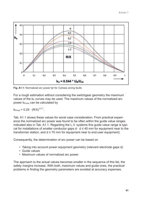
Fig. A1.1: Normalized <strong>arc</strong> power kP for 3-phase <strong>arc</strong>ing <strong>fault</strong>s<br />
For a rough estimation without considering the switchgear geometry the maximum<br />
values of the kP curves may be used. The maximum values of the normalized <strong>arc</strong><br />
power kPmax c<strong>an</strong> be calculated by<br />
kPmax = 0.29 . (R/X) -0,17 .<br />
Annex 1<br />
Tab. A1.1 shows these values for worst case consideration. From practical experience<br />
the normalized <strong>arc</strong> power was found to be often within the guide value r<strong>an</strong>ges<br />
indicated also in Tab. A1.1. Regarding the L.V. systems th<strong>is</strong> guide value r<strong>an</strong>ge <strong>is</strong> typical<br />
for installations of smaller conductor gaps d: d ≤ 40 mm for equipment near to the<br />
tr<strong>an</strong>sformer station, <strong>an</strong>d d ≤ 70 mm for equipment near to end-user equipment).<br />
Consequently, the determination of <strong>arc</strong> power c<strong>an</strong> be based on<br />
• Taking into account power equipment geometry (relev<strong>an</strong>t electrode gaps d)<br />
• Guide values<br />
• Maximum values of normalized <strong>arc</strong> power.<br />
The approach to the actual values becomes smaller in the sequence of th<strong>is</strong> l<strong>is</strong>t, the<br />
safety margins increase. With both, maximum values <strong>an</strong>d guide ones, the practical<br />
problems in finding the geometry parameters are avoided at accuracy expenses.<br />
41