LP6 Plus Volume Ventilator -And- LP10 Volume Ventilator With ...
LP6 Plus Volume Ventilator -And- LP10 Volume Ventilator With ...
LP6 Plus Volume Ventilator -And- LP10 Volume Ventilator With ...

Create successful ePaper yourself
Turn your PDF publications into a flip-book with our unique Google optimized e-Paper software.
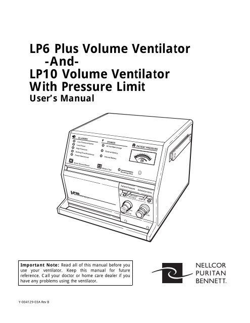
<strong>LP6</strong> <strong>Plus</strong> <strong>Volume</strong> <strong>Ventilator</strong><br />
-<strong>And</strong>-<br />
<strong>LP10</strong> <strong>Volume</strong> <strong>Ventilator</strong><br />
<strong>With</strong> Pressure Limit<br />
User’s Manual<br />
Important Note: Read all of this manual before you<br />
use your ventilator. Keep this manual for future<br />
reference. Call your doctor or home care dealer if you<br />
have any problems using the ventilator.<br />
Y-004129-03A Rev B
page ii<br />
For more<br />
information:<br />
©Copyright 1999, Nellcor Puritan Bennett Inc., Minneapolis, Minnesota U.S.A. All rights<br />
reserved. No portion of this manual may be copied, reproduced, or stored in any form without the<br />
express written permission of Nellcor Puritan Bennett, Inc.<br />
Contact your Nellcor Puritan Bennett representative for information on our full line of medical<br />
equipment and related services. Or, you may contact Nellcor Puritan Bennett directly. Phone:<br />
(800) 497-4979<br />
In Europe contact:<br />
Nellcor Puritan Bennett Europe BV<br />
Hambakenwetering 1<br />
5231 DD ‘s-Hertogenbosch<br />
The Netherlands<br />
Telephone: +31.73.648.5200<br />
Fax: +31.73.641.0915<br />
June 1999
<strong>LP6</strong> <strong>Plus</strong> and <strong>LP10</strong> User’s Manual<br />
June 1999<br />
Contents<br />
Contents<br />
Purpose of this Manual . . . . . . . . . . . . . . . . . . . . . . . . . . . . . . . . . . . . . . . .2<br />
Symbols and definitions . . . . . . . . . . . . . . . . . . . . . . . . . . . . . . . . . . . . . . . .4<br />
Electrical Interference . . . . . . . . . . . . . . . . . . . . . . . . . . . . . . . . . . . . .5<br />
Introduction and Overview . . . . . . . . . . . . . . . . . . . . . . . . . . . . . . . . . . . . .6<br />
General Description . . . . . . . . . . . . . . . . . . . . . . . . . . . . . . . . . . . . . . . . . . .9<br />
Patient <strong>Ventilator</strong> Circuit . . . . . . . . . . . . . . . . . . . . . . . . . . . . . . . . . . .9<br />
Front Panel . . . . . . . . . . . . . . . . . . . . . . . . . . . . . . . . . . . . . . . . . . . . .12<br />
Rear Panel . . . . . . . . . . . . . . . . . . . . . . . . . . . . . . . . . . . . . . . . . . . . .15<br />
Installation . . . . . . . . . . . . . . . . . . . . . . . . . . . . . . . . . . . . . . . . . . . . . . . . .17<br />
Mounting or Positioning . . . . . . . . . . . . . . . . . . . . . . . . . . . . . . . . . .17<br />
Emergency Vehicle . . . . . . . . . . . . . . . . . . . . . . . . . . . . . . . . . . . . . .18<br />
Wheelchair . . . . . . . . . . . . . . . . . . . . . . . . . . . . . . . . . . . . . . . . . . . . .19<br />
Power Sources . . . . . . . . . . . . . . . . . . . . . . . . . . . . . . . . . . . . . . . . . . . . . .20<br />
AC Power . . . . . . . . . . . . . . . . . . . . . . . . . . . . . . . . . . . . . . . . . . . . . .20<br />
External Battery 12 Volt DC . . . . . . . . . . . . . . . . . . . . . . . . . . . . . . .21<br />
Using a Car Battery . . . . . . . . . . . . . . . . . . . . . . . . . . . . . . . . . . . . . .22<br />
Battery Performance . . . . . . . . . . . . . . . . . . . . . . . . . . . . . . . . . . . . . .23<br />
Testing the Batteries . . . . . . . . . . . . . . . . . . . . . . . . . . . . . . . . . . . . . .24<br />
Special Precautions for External Battery . . . . . . . . . . . . . . . . . . . . . .24<br />
Internal Battery 12 Volt DC . . . . . . . . . . . . . . . . . . . . . . . . . . . . . . . .25<br />
Operating Controls . . . . . . . . . . . . . . . . . . . . . . . . . . . . . . . . . . . . . . . . . . .26<br />
Operating Modes . . . . . . . . . . . . . . . . . . . . . . . . . . . . . . . . . . . . . . . . . . . .28<br />
Standby . . . . . . . . . . . . . . . . . . . . . . . . . . . . . . . . . . . . . . . . . . . . . . . .28<br />
Assist/Control . . . . . . . . . . . . . . . . . . . . . . . . . . . . . . . . . . . . . . . . . . .28<br />
Assist/Control with Pressure Limit (<strong>LP10</strong> Only) . . . . . . . . . . . . . . . .28<br />
SIMV (Synchronized Intermittent Mandatory Ventilation) . . . . . . .28<br />
SIMV with Pressure Limit (<strong>LP10</strong> Only) . . . . . . . . . . . . . . . . . . . . . .29<br />
Pressure Cycle . . . . . . . . . . . . . . . . . . . . . . . . . . . . . . . . . . . . . . . . . .29<br />
Pressure Limit (<strong>LP10</strong> Only) . . . . . . . . . . . . . . . . . . . . . . . . . . . . . . . .30<br />
Routine Safety Check . . . . . . . . . . . . . . . . . . . . . . . . . . . . . . . . . . . . . . . .32<br />
Monthly Safety Check . . . . . . . . . . . . . . . . . . . . . . . . . . . . . . . . . . . . . . . .34<br />
Responding To Alarms . . . . . . . . . . . . . . . . . . . . . . . . . . . . . . . . . . . . . . .36<br />
Troubleshooting Guide . . . . . . . . . . . . . . . . . . . . . . . . . . . . . . . . . . . . . . .38<br />
Cleaning and Maintenance . . . . . . . . . . . . . . . . . . . . . . . . . . . . . . . . . . . . .40<br />
Patient Circuit and Humidifier . . . . . . . . . . . . . . . . . . . . . . . . . . . . . .40<br />
Inlet Air Filter . . . . . . . . . . . . . . . . . . . . . . . . . . . . . . . . . . . . . . . . . .41<br />
<strong>Ventilator</strong> Surface . . . . . . . . . . . . . . . . . . . . . . . . . . . . . . . . . . . . . . .42<br />
Storage of the <strong>Ventilator</strong> . . . . . . . . . . . . . . . . . . . . . . . . . . . . . . . . . .42<br />
Scheduled Maintenance . . . . . . . . . . . . . . . . . . . . . . . . . . . . . . . . . . .43<br />
Specifications . . . . . . . . . . . . . . . . . . . . . . . . . . . . . . . . . . . . . . . . . . . . . . .45<br />
Service Policy . . . . . . . . . . . . . . . . . . . . . . . . . . . . . . . . . . . . . . . . . . . . . .47<br />
Limited Warranty . . . . . . . . . . . . . . . . . . . . . . . . . . . . . . . . . . . . . . . . . . . .48<br />
Keyword Index . . . . . . . . . . . . . . . . . . . . . . . . . . . . . . . . . . . . . . . . . . . . . .51<br />
Page 1
Purpose of this Manual<br />
Purpose of this Manual<br />
Page 2<br />
<strong>LP6</strong> <strong>Plus</strong> and <strong>LP10</strong> User’s Manual<br />
This manual contains valuable information. Remember, your ventilator is<br />
an electrical device. It will provide years of useful service with the proper<br />
care. This manual tells you how to give it that care.<br />
As you read this manual, you’ll notice Cautions and Warnings in boxes<br />
on many pages. Pay very special attention to these boxes. They will tell<br />
you what to do and what to avoid as you use your ventilator.<br />
The difference between Warnings and Cautions is:<br />
A Warning contains information about possible hazards to the patient,<br />
the care provider, or the service technician.<br />
A Caution includes information about how to avoid equipment damage.<br />
Warnings Always follow the physician’s prescription when using the ventilator.<br />
Always operate and store the ventilator according to the specifications<br />
and instructions set forth in this manual.<br />
Use only Nellcor Puritan Bennett-approved accessories and products<br />
with the ventilator. The use of other accessories may damage<br />
the unit and endanger the patient.<br />
Perform daily and monthly verification of the ventilator’s operation<br />
as identified in this manual.Always stabilize and verify ventilator<br />
performance before connecting the patient to the unit.<br />
All alarms indicate a potential risk to patient safety. When an<br />
alarm sounds, provide immediate attention, care, and support to<br />
the patient as dictated by the situation.<br />
Do not use in direct sunlight.<br />
June 1999
<strong>LP6</strong> <strong>Plus</strong> and <strong>LP10</strong> User’s Manual<br />
June 1999<br />
.<br />
Purpose of this Manual<br />
Caution Refer any adjustments or procedures exceeding the scope of this manual<br />
to your physician, homecare provider, or a Nellcor Puritan Bennett Service<br />
Representative. Refer to the Nellcor Puritan Bennett Service Policy<br />
found on page 47.<br />
CAUTION: Federal Law (U.S.A.) restricts this device to sale or use by<br />
or on the order of a licensed physician.<br />
Warnings The <strong>LP6</strong> <strong>Plus</strong> and <strong>LP10</strong> ventilators shall not be used with flammable<br />
anesthetic agents.<br />
Page 3
Symbols and definitions<br />
<strong>LP6</strong> <strong>Plus</strong> and <strong>LP10</strong> User’s Manual<br />
Symbols and definitions<br />
The following symbols appear on the <strong>LP6</strong> <strong>Plus</strong> and <strong>LP10</strong> ventilators.<br />
Page 4<br />
I Power switch ON position, connection to mains power<br />
O Power switch OFF position, disconnection from mains power<br />
!<br />
Attention, consult accompanying manual.<br />
Alternating current<br />
Direct current<br />
V Volts<br />
A Amperes<br />
Standby mode of operation<br />
Canadian Standards Association<br />
Battery test switch<br />
Alarm silence switch<br />
Alarm<br />
Power<br />
Underwriters Laboratories, Inc.<br />
Patient pressure<br />
External battery connection<br />
Remote alarm<br />
Battery test level<br />
Manual reset<br />
June 1999
<strong>LP6</strong> <strong>Plus</strong> and <strong>LP10</strong> User’s Manual<br />
Electrical Interference<br />
June 1999<br />
Symbols and definitions<br />
Caution Your ventilator is an electronic instrument. Any electronic instrument<br />
is subject to electrical interference. Electrical interference in excess of<br />
10 V/m may keep your ventilator from working properly.<br />
Television sets, cordless or cellular telephones, microwave ovens, air conditioners,<br />
food processors, and other appliances can be sources of electrical<br />
interference. To avoid electrical interference between your ventilator and<br />
these appliances, you must follow these instructions:<br />
• Never place your ventilator near these appliances.<br />
• Never plug the ventilator into the same A.C. electrical outlet as these<br />
appliances, nor into electrical outlets on the same circuit as these<br />
appliances.<br />
• Never place the cables from ventilator accessories near these appliances.<br />
Warning Electrical interference may keep your ventilator from working<br />
properly, which may create a hazard to the patient.<br />
Note The ventilator is exempt under Section 15.801 (c)(5) of the no interference<br />
regulations adopted by the FCC. If television interference does occur, contact<br />
Technical Services at Nellcor Puritan Bennett, Inc. or a television<br />
repair technician for suggestions. Or, move the television to an A.C. electrical<br />
outlet that does not allow interference.<br />
Page 5
Introduction and Overview<br />
Introduction and Overview<br />
Page 6<br />
<strong>LP6</strong> <strong>Plus</strong> and <strong>LP10</strong> User’s Manual<br />
The Nellcor Puritan Bennett Model <strong>LP6</strong> <strong>Plus</strong> and <strong>LP10</strong> <strong>Volume</strong> <strong>Ventilator</strong>s<br />
are intended for use in a non-acute ventilator care environment for<br />
pediatrics and adults. They are to be operated in accordance with the product<br />
labeling contained in the instruction manuals.<br />
The ventilator is a microprocessor-controlled volume ventilator. It provides<br />
continuous respiratory support for patients with respiratory insufficiencies<br />
in a home or hospital, or during transport. Because of its compact<br />
design and light weight, the unit is highly portable.<br />
The ventilator offers a wide range of delivery volumes, inspiratory times,<br />
and breathing rates. The physician or the respiratory therapist can set the<br />
appropriate ventilation parameters via the controls located in the recessed<br />
front panel. The magnetically latched door panel and the control knobs are<br />
designed to help prevent tampering and accidental resetting.<br />
June 1999
<strong>LP6</strong> <strong>Plus</strong> and <strong>LP10</strong> User’s Manual<br />
June 1999<br />
Introduction and Overview<br />
Your doctor has prescribed a ventilator. A ventilator’s main purpose is to<br />
help you breathe. You need this help because of your medical condition.<br />
Before getting into the ventilator’s operation, let’s look at how breathing<br />
happens. People don’t give much thought to breathing, because it’s something<br />
most of us take for granted.<br />
Air contains oxygen. A person cannot live without oxygen. It’s one of the<br />
fuels that keeps our bodies going. Oxygen transfers to the blood in the<br />
lungs. The blood goes to the heart which then pumps it to all parts of the<br />
body. As the blood delivers oxygen to the body’s cells, it picks up and<br />
returns carbon dioxide to the lungs. Carbon dioxide transfers to the air in<br />
the lungs and leaves the body when a person exhales.<br />
People inhale (breathe in) when their diaphragm drops (contracts) and<br />
their ribs move out. This motion expands the lungs which then have a<br />
negative pressure compared to the surrounding air. As a result, air rushes<br />
into the lungs. We call this inspiration.<br />
People exhale (breathe out) when they relax their muscles. Their diaphragms<br />
move up (relax) and their ribs squeeze in. This motion compresses<br />
the lungs and forces out the used air. We call this expiration.<br />
We call this whole process RESPIRATION. Every step of the process is<br />
important. RESPIRATORY INSUFFICIENCY or FAILURE occurs when<br />
a person cannot complete one or more of these steps.<br />
A person with respiratory insufficiency or failure may need a ventilator. It<br />
makes up for a missing step or steps in the respiration process. Your <strong>LP6</strong><br />
<strong>Plus</strong> or <strong>LP10</strong> <strong>Volume</strong> <strong>Ventilator</strong> helps you breathe by gently moving air<br />
into your lungs. It does this in one of two ways. If you are strong enough<br />
to start a breath, the ventilator times its action to your efforts. These are<br />
assisted breaths. Depending on its settings, the ventilator may assist some<br />
or all of your breaths. But, if you cannot start the breathing process, the<br />
ventilator will deliver controlled breaths. Your doctor has prescribed how<br />
many times a minute you will receive these controlled breaths.<br />
That’s the way the ventilator helps you get the oxygen your body needs. As<br />
you exhale after every assisted or controlled breath, you rid your body of<br />
carbon dioxide.<br />
The pages that follow describe the ventilator in detail. Read all the information<br />
carefully. If you don’t understand something, ask your doctor, your<br />
caregiver, or a service technician to explain it.<br />
Page 7
Introduction and Overview<br />
Page 8<br />
Patient <strong>Ventilator</strong> Circuit<br />
<strong>LP6</strong> <strong>Plus</strong> and <strong>LP10</strong> User’s Manual<br />
June 1999
<strong>LP6</strong> <strong>Plus</strong> and <strong>LP10</strong> User’s Manual<br />
General Description<br />
June 1999<br />
General Description<br />
Patient <strong>Ventilator</strong> Circuit The Patient <strong>Ventilator</strong> Circuit has a long flexible hose and several other<br />
parts shown in the diagram. It attaches to the ventilator and is your link to<br />
the breaths you need. Inspect it every day to:<br />
• Make sure there are no cracks in the hose.<br />
• Be certain all the connections fit securely to prevent leaks.<br />
• Clean the Exhalation Manifold daily.<br />
• Replace parts regularly before they wear out. Regular replacement is<br />
essential for successful ventilation. See the instructions that came<br />
with your patient ventilator circuit.<br />
A. Flex Tube: Use this tube to connect the Patient <strong>Ventilator</strong> Circuit to<br />
a tube adaptor on your trach tube. The tube’s flexibility makes the<br />
circuit more comfortable.<br />
B. Exhalation Manifold: The Exhalation Manifold directs the flow of<br />
gases to and from the patient. Broadly speaking, this assembly consists<br />
of a manifold body, a mushroom valve, and a cap. Refer to the<br />
manufacturer’s instructions. Before using it with the patient, secure<br />
all connections and ensure the seating of the mushroom valve.<br />
During inhalation, the white mushroom inflates and allows air to<br />
enter your lung. During exhalation, the mushroom deflates and<br />
allows you to expel air from your lungs.<br />
Make sure this valve prevents the escape of any gases during inspiration<br />
and that it releases properly during exhalation.<br />
Note For your safety, upon start-up, the ventilator dumps the first breath<br />
through the exhalation manifold. The unit’s microprocessor requires one<br />
cycle to establish its reference point; that is, the operating mode and settings<br />
to use. This operation prevents delivery of incorrect volumes that<br />
could result in excessive pressure build-up.<br />
Page 9
General Description<br />
Page 10<br />
<strong>LP6</strong> <strong>Plus</strong> and <strong>LP10</strong> User’s Manual<br />
Warning Ensure the proper connection and operation of the patient ventilator<br />
circuit daily. The patient could be at risk if the manifold<br />
does not function as intended. Connecting patient pressure and<br />
exhalation tubes to the incorrect port prevents proper patient<br />
ventilation.<br />
C. Patient Air Hose: This is the large hose between the Bacteria Filter<br />
and the Exhalation Manifold.<br />
D. Patient Pressure Tube (included with patient air hose): This small<br />
tube connects the Patient Pressure port on the ventilator to the Exhalation<br />
Manifold.<br />
E. Exhalation Tube (included with patient air hose): This small tube<br />
connects the Exhalation Valve port to the Exhalation Manifold.<br />
F. Bacteria Filter: This filter cleans the incoming air before you inhale<br />
it.<br />
Other accessories are available. When using any accessory, always follow<br />
the manufacturer’s recommendations and instructions.<br />
Caution Adding attachments or other components to the breathing system will<br />
increase the inspiratory and expiratory resistance.<br />
June 1999
<strong>LP6</strong> <strong>Plus</strong> and <strong>LP10</strong> User’s Manual<br />
June 1999<br />
General Description<br />
Warnings Some active humidifiers do not have temperature monitoring or<br />
alarm capabilities. Failure to monitor air temperature may allow<br />
inspired air to become too hot. Thermal injury to the patient’s airway<br />
may result. Always follow the recommendation of the humidifier<br />
manufacturer.<br />
To ensure the prescribed oxygen concentrations are delivered to<br />
the patient, measure the oxygen with a calibrated analyzer.<br />
A ventilator patient is highly susceptible to respiratory infections.<br />
Dirty or infected equipment may be a source of infection. Clean<br />
equipment and proper use of bacteria filters are essential to<br />
reduce the chance of infection.<br />
Always use a Bacteria Filter to minimize the risk of respiratory<br />
infection.<br />
Antistatic or electrically conductive hoses or tubing should not be<br />
used.<br />
Page 11
General Description<br />
Page 12<br />
Front Panel The Front Panel of the ventilator has three sections:<br />
<strong>LP6</strong> <strong>Plus</strong> and <strong>LP10</strong> User’s Manual<br />
• The upper section has small lights, two touch button pads, and a<br />
meter.<br />
• The lower left section has the operating controls. Your doctor prescribes<br />
their setting. To prevent accidental resetting, they are behind a<br />
closed panel.<br />
• The lower right section has the pressure limit controls (<strong>LP10</strong> only) and<br />
the connections for the Patient Circuit.<br />
Upper Section<br />
1<br />
2<br />
1. Alarm Lights: When flashing or continuously lit, they identify a condition<br />
that demands immediate attention. There is also an audible<br />
tone when these lights begin flashing.<br />
2. Alarm Silence/Reset Button: This has five uses.<br />
• Push to test the alarms.<br />
• Push to silence alarms for 60 seconds.<br />
• Push to reset the alarm after correcting the problem.<br />
• Push simultaneously with the Battery Test Button for operating hours.<br />
(See the Scheduled Maintenance portion of the manual, page 43.)<br />
• Use this button with other controls to start the self-test (see page 35).<br />
3. Power Source Lights:<br />
3<br />
4 5<br />
• The top light is green when the ventilator is AC powered.<br />
• The middle light is amber when an external battery powers the ventilator.<br />
• The bottom light flashes amber when the ventilator’s internal battery<br />
is in use. A single tone also beeps every five minutes.<br />
6<br />
June 1999
<strong>LP6</strong> <strong>Plus</strong> and <strong>LP10</strong> User’s Manual<br />
June 1999<br />
General Description<br />
4. Battery Test Button: It has four uses.<br />
• When pressed, the Pressure Meter displays the charge status of the<br />
battery in use (internal or optional external battery) when the ventilator<br />
is disconnected from AC power.<br />
• Push simultaneously with the Alarm Silence/Reset button for an indication<br />
of operating hours. (See the Scheduled Maintenance portion of<br />
this manual, page 43.)<br />
• Press the button to print a report from an attached printer.<br />
• Use this button with other controls to start the self-test (see page 35).<br />
5. Breathing Effort Light: This light turns green whenever the ventilator<br />
senses your effort to breathe. The Breathing Effort control sets the<br />
sensitivity.<br />
6. Patient Pressure Meter: The meter displays three pieces of information:<br />
• Pressure at the Exhalation Manifold.<br />
• The number of hours of ventilator operation.<br />
• The charge status of the internal or attached external battery.<br />
Lower Left Section<br />
1<br />
2<br />
3<br />
1. Control Panel Door: This door is latched magnetically to protect the<br />
controls from accidental resetting.<br />
2. Alarm Reference Guide: Consult this guide for a summary of alarms<br />
and the action you should take. You will find the Guide on the inside<br />
of the Control Panel Door.<br />
3. Control Knobs: They are behind the closed Control Panel Door. Your<br />
doctor prescribes the settings for these controls. See page 26 for<br />
details.<br />
Page 13
General Description<br />
Page 14<br />
Lower Right Section<br />
<strong>LP6</strong> <strong>Plus</strong> and <strong>LP10</strong> User’s Manual<br />
1. Patient Air Tube: The Patient air hose connects to this tube. The<br />
ventilator delivers air through this tube.<br />
2. Exhalation Valve Port: The Exhalation Pressure Tube of the Patient<br />
Circuit connects to this port.<br />
3. Patient Pressure Port: The Patient Pressure Tube of the Patient Circuit<br />
connects to this port.<br />
4. Pressure Limit Control (<strong>LP10</strong> Only): This control sets the air pressure<br />
limit during a breath. For use in Assist/Control or SIMV modes<br />
only; use in other modes may not allow effective ventilation.<br />
June 1999
<strong>LP6</strong> <strong>Plus</strong> and <strong>LP10</strong> User’s Manual<br />
Rear Panel<br />
Mounting<br />
Rails<br />
14<br />
Inlet<br />
Filter<br />
1<br />
11<br />
Pressure<br />
Relief<br />
June 1999<br />
10<br />
2 13 3<br />
Cord Wrap<br />
Rear Feet<br />
Vent<br />
AC Plug<br />
Voltage<br />
Select<br />
Carrying<br />
Handle<br />
External<br />
12 Volt DC<br />
Battery<br />
9 8 6 7<br />
AC Power<br />
Switch<br />
General Description<br />
Remote Alarm<br />
Connector<br />
DC Circuit<br />
Breaker<br />
12<br />
Communication<br />
Port<br />
4<br />
5<br />
Serial Number<br />
Plate<br />
Page 15
General Description<br />
Page 16<br />
<strong>LP6</strong> <strong>Plus</strong> and <strong>LP10</strong> User’s Manual<br />
1. Inlet Filter: The ventilator draws in air through this filter.<br />
Warning Do not block the inlet filter port. (Keep away from curtains.)<br />
2. Cord Wrap and Rear Feet: There is a foot at each corner.<br />
3. AC Power Switch/Circuit Breaker: This is the ON/OFF switch for<br />
AC power. It also has a built-in circuit breaker. 1 is power connected<br />
to mains and 0 is power disconnected from mains.<br />
4. Communications Port: A special cable fits here and leads to an<br />
optional printer.<br />
Note The ventilator and printer should be turned off before connection or disconnection<br />
of the printer.<br />
5. Serial Number Plate: This has Nellcor Puritan Bennett’s identification<br />
number for the ventilator. It also lists the unit’s power requirements.<br />
6. External 12 Volt DC Battery Connector: This is where you plug in<br />
an external battery cable.<br />
7. Remote Alarm Connection: A remote alarm (optional) can summon<br />
the caregiver when an alarm sounds.<br />
8. Rear Carrying Handle Recess<br />
9. AC Plug Holder<br />
10. Vent: Warm air from the unit’s circuitry leaves the ventilator and cool<br />
air enters through this vent. This cools the ventilator.<br />
Warning Do not block rear panel vent<br />
11. Pressure Relief: This prevents the air pressure from exceeding<br />
approximately 100 cmH 2O/hPa.<br />
Warning Do not block the pressure relief valve.<br />
12. DC Circuit Breaker: This circuit breaker protects the ventilator when<br />
it is powered by an external battery.<br />
June 1999
<strong>LP6</strong> <strong>Plus</strong> and <strong>LP10</strong> User’s Manual<br />
Installation<br />
June 1999<br />
Installation<br />
13. Voltage Select Switch: This switch selects 110 or 220 volts when it is<br />
powered by an external battery<br />
Caution An incorrect switch setting may damage your ventilator.<br />
14. Mounting Rails: These are used to mount and connect accessories to<br />
the ventilator.<br />
Mounting or Positioning Position the ventilator on a table or nightstand within six feet of an electrical<br />
outlet.<br />
Keep the rear panel free of draperies or other items that could impede the<br />
air flow to the Inlet Filter port.<br />
Protect the ventilator from accidental liquid spills. Never place food or<br />
liquids on top of the ventilator. When used in a humid environment,<br />
and when cleaning:<br />
• Take precautions to protect the setting switches.<br />
• Keep the front panel door closed.<br />
• Avoid spilling or allowing liquid to enter the unit.<br />
Allow for the space requirements of additional equipment, e.g., humidification<br />
and supplemental oxygen. When in use, keep active humidifiers or<br />
the patient circuit at an elevation lower than the patient’s trachea. Moreover,<br />
keep the humidifier and the circuit lower than the ventilator’s<br />
Patient Air tube to prevent moisture from entering the ventilator.<br />
Warning Never allow liquids to contact internal ventilator components<br />
under any circumstances. Moisture will damage the ventilator.<br />
Page 17
Installation<br />
Page 18<br />
<strong>LP6</strong> <strong>Plus</strong> and <strong>LP10</strong> User’s Manual<br />
During transport in cars and vans, securely position the ventilator and<br />
strap it down to avoid inadvertent jarring or damage.<br />
You may connect the ventilator to the car’s battery power with an accessory<br />
power cable equipped with a cigarette lighter plug. Connect the ventilator<br />
to the cigarette lighter cable/plug only after the car’s motor is<br />
running.<br />
Warning Do not block the alarm port.<br />
Emergency Vehicle In an emergency vehicle, employ a deck or mounting bracket to secure the<br />
ventilator. Maintain at least four inches between the rear panel Inlet Filter<br />
and the vehicle’s wall. Position the ventilator to easily view all indicators<br />
with ready access to all operating controls.<br />
Warning AC power sources in ambulances and aircraft are frequently<br />
unregulated. As a result, the ventilator may be exposed to high<br />
voltage levels that can damage it. Operation of the ventilator on<br />
improper power sources voids the warranty and could seriously<br />
damage the unit.<br />
Before plugging the ventilator into an unknown power source, check the<br />
voltage. If the power source exceeds the proper range at any time, or if the<br />
voltage cannot be verified, use a 12 VDC battery, rather than risk damage<br />
to the ventilator.<br />
Warnings Do not use a power converter as a power source for the ventilator.<br />
Stabilize and verify proper ventilator performance before connecting<br />
the patient to the ventilator.<br />
June 1999
<strong>LP6</strong> <strong>Plus</strong> and <strong>LP10</strong> User’s Manual<br />
June 1999<br />
Installation<br />
Wheelchair Mounting instructions vary from chair to chair. Consult the wheelchair<br />
manufacturer for standard wheelchair adaptations.<br />
Here are some general guidelines to consider when using the ventilator in<br />
a wheelchair.<br />
• When using a tray, place a partition between the battery and ventilator.<br />
• Insert a partition in the tray mount between the ventilator and battery.<br />
Locate this partition as far as possible from the ventilator’s Inlet Filter.<br />
If the ventilator and battery are in the same tray, cut drain holes in the<br />
tray to prevent any leaking battery fluid from reaching the ventilator.<br />
Place the battery in a plastic container to help insulate the ventilator<br />
from battery fluid.<br />
• Always provide an external battery as the power source.<br />
• Never use the same battery to power a motorized wheelchair and the<br />
ventilator at the same time.<br />
• Protect the ventilator from spills and water seepage during bad<br />
weather or other conditions when using the unit on a wheelchair.<br />
• Check the Air Inlet Filter frequently when using the ventilator outdoors,<br />
especially when the Air Inlet is pointed toward the ground.<br />
• To maintain a full charge on the internal battery, you must routinely<br />
connect any ventilator mounted on a wheelchair to AC power while<br />
the wheelchair is not in use. You must connect the ventilator to AC<br />
power as soon as possible after internal battery operation, no matter<br />
how short a time the ventilator operated on internal battery.<br />
Warnings Always place the external battery as far away from the ventilator<br />
as possible. The distance will help prevent battery gases from<br />
drifting toward the ventilator’s air inlet.<br />
Never place an external battery above the ventilator. Use separate<br />
batteries to simultaneously power an electric wheelchair and the<br />
ventilator.<br />
Page 19
Power Sources<br />
Power Sources<br />
Page 20<br />
Any one of three power sources can power the ventilator.<br />
• External AC,<br />
• External 12 VDC battery, or<br />
• Internal 12 VDC battery.<br />
<strong>LP6</strong> <strong>Plus</strong> and <strong>LP10</strong> User’s Manual<br />
When plugged into a functioning wall outlet with the AC power switch<br />
ON, the ventilator automatically selects the AC power source. It will operate<br />
indefinitely on AC. All three sources may be connected to the ventilator<br />
at the same time. If the AC power fails, the ventilator automatically<br />
switches to the next best power source.<br />
When used at home or in the hospital, plug the ventilator into a convenient<br />
wall socket. If you use the ventilator in a wheelchair or in a car, connect<br />
it to an external 12 Volt DC battery. Your ventilator has an internal<br />
battery. Use the internal battery for short-term emergencies only, for<br />
example, when moving from one power source to another. Make sure you<br />
recharge the internal battery immediately after each use.<br />
Warning The batteries contain toxic chemicals and no attempt to remove<br />
or replace the batteries should be made by any one other than the<br />
home care dealer or an authorized service center.<br />
AC Power Plug the ventilator into the appropriate AC grounded wall outlet.<br />
Warning The ventilator must be set to the proper AC line voltage before<br />
plugging it into the AC outlet.<br />
The ventilator automatically operates from AC power when you plug it in.<br />
Make sure that you plug the cord into a properly grounded outlet.<br />
Warning The ventilator must be protectively earthed when operating from<br />
an AC power source. If you have any doubts about the outlet’s<br />
ground connection, have a qualified electrician examine the outlet.<br />
June 1999
<strong>LP6</strong> <strong>Plus</strong> and <strong>LP10</strong> User’s Manual<br />
June 1999<br />
Power Sources<br />
The ventilator requires 0.5 amps (typical) at 110 VAC. If the voltage<br />
select switch is set to 110 V, the supplied voltage must be between 100<br />
and 127 VAC.<br />
The ventilator requires 0.3 amps (typical) at 220 VAC. If the voltage<br />
select switch is set to 220 V, the supplied voltage must be between 220<br />
and 240 VAC.<br />
Your ventilator automatically recharges its internal battery whenever it is:<br />
• plugged into an AC outlet, and<br />
• the AC Power Switch is ON (1)<br />
You can also recharge an external battery that is properly connected to<br />
your ventilator. (See pages 21 through 23.)<br />
When traveling to another country (or to a region with a different power system),<br />
you may encounter two problems. First, the nominal voltage may be<br />
different. Note the ranges given above for 110 and 220 VAC respectively.<br />
The second problem you may encounter is the plug itself. It may not fit<br />
into the outlet. There are two solutions. First, have a qualified electrician<br />
remove and replace the ventilator’s plug with one designed for the local<br />
outlets. Second, you may use an adaptor. Make certain that the adaptor has<br />
no active electronic components and that it is not a power converter.<br />
Caution If you have any questions about the power system or how the ventilator<br />
will operate, contact a qualified electrician and/or Nellcor Puritan Bennett.<br />
External Battery<br />
12 Volt DC<br />
If you are away from an AC power outlet, you can operate your ventilator<br />
from a 12 Volt DC battery. Nellcor Puritan Bennett recommends the use<br />
of a deep-cycle, gel-cell battery.<br />
Carefully connect the 12 Volt DC battery to the ventilator. Use only<br />
Nellcor Puritan Bennett battery cables. Follow the instructions included<br />
with the battery cable to ensure proper connection.<br />
Caution Do not use the ventilator with a 24 VDC external battery.<br />
A Power Switchover alarm sounds whenever the ventilator starts using<br />
power from an attached external battery.<br />
Check to see if the ventilator’s External Battery light is lit. This light signals<br />
that your ventilator is properly connected and is using the external<br />
battery.<br />
Page 21
Power Sources<br />
Page 22<br />
<strong>LP6</strong> <strong>Plus</strong> and <strong>LP10</strong> User’s Manual<br />
Note Do not reverse the positive and negative cables when connecting a battery<br />
to your ventilator. If you accidentally reverse the connections, a protective<br />
fuse in the battery cable or the ventilator’s DC circuit breaker opens. The<br />
cable will not provide power to the ventilator. You must first correct the<br />
connections and install a correct replacement fuse in the cable. Reset the<br />
DC circuit breaker on the ventilator. Only then will the external battery<br />
power the ventilator.<br />
You may order batteries and connecting cables from Nellcor Puritan Bennett.<br />
These accessories come with specific instructions for connection and<br />
use. The battery and case provided by Nellcor Puritan Bennett have a cable<br />
with a 3-pin connector. When properly used, this cable/connector ensures<br />
against reversing the connections between the battery and ventilator. Use<br />
of other cables may damage the ventilator or make it inoperable when the<br />
cable connections are accidentally reversed.<br />
Warning Always place the external battery as far away from the ventilator<br />
as possible. The distance will help prevent battery gases from<br />
drifting toward the ventilator’s air inlet.<br />
Using a Car Battery The ventilator will operate from a car battery. Connect the ventilator to<br />
the car with a cigarette plug cable from Nellcor Puritan Bennett. Make<br />
sure the vehicle is running when the ventilator is drawing power. Otherwise,<br />
the ventilator may run down the car’s battery.<br />
Caution Always start the vehicle before connecting the ventilator to the car battery.<br />
Starting a vehicle when the ventilator is connected may damage<br />
the ventilator and void the warranty.<br />
June 1999
<strong>LP6</strong> <strong>Plus</strong> and <strong>LP10</strong> User’s Manual<br />
June 1999<br />
Power Sources<br />
Battery Performance As they age and due to their chemical make-up, batteries lose their capacity<br />
to retain an electrical charge. Typically lead-acid batteries lose 7% of<br />
their capacity each year. For best performance, follow the manufacturer’s<br />
instructions.<br />
The following affect the life of the battery:<br />
• Ambient temperature,<br />
• Charge level,<br />
• Storage conditions,<br />
• Time, and<br />
• The number of “deep cycles.”<br />
For maximum efficiency, operate or store the battery at room temperatures.<br />
It will charge and discharge most efficiently in such an environment.<br />
To ensure maximum running time of the ventilator on any external battery,<br />
keep the battery fully charged. Some batteries need to be discharged<br />
and recharged monthly. Recharge any external battery immediately after<br />
use. Refer to the battery manufacturer’s instructions. The time required to<br />
recharge a battery varies. Generally, with a 10 amp standard charger, there<br />
is a 1:1 ratio (one hour of recharge for each hour of use).<br />
Cautions Recharge an external battery immediately after use. You must use a<br />
standard battery charger to recharge external batteries used for extended<br />
periods of time. Do not use the ventilator’s internal charger to recharge<br />
deeply discharged batteries.<br />
First connect the battery to the standard charger. Then connect the<br />
charger to AC power.<br />
NEVER connect a battery charger to an external battery while the battery<br />
is connected to the ventilator.<br />
A 30 to 40 amp hour battery, in good condition can power the ventilator<br />
for about 10 hours without recharging. A 75 to 80 amp hour battery provides<br />
power for about 20 hours between charges.<br />
Page 23
Power Sources<br />
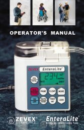
Number of Cycles<br />
1400<br />
1200<br />
1000<br />
800<br />
600<br />
400<br />
200<br />
0<br />
Page 24<br />
<strong>LP6</strong> <strong>Plus</strong> and <strong>LP10</strong> User’s Manual<br />
Testing the Batteries Make sure that the external or internal battery is powering the ventilator<br />
before testing the battery condition. To run the test, press and hold the<br />
Battery Test button. The needle on Patient Pressure Meter registers the<br />
battery status in the window below. A fully charged battery in good condition<br />
will register in the Normal/High range.<br />
20 40 60 80 100 120<br />
Depth of Discharge (%)<br />
Special Precautions for<br />
External Battery<br />
Note The Battery Test meter is only a relative indicator of the remaining battery<br />
charge. An older battery may register a high charge level, but discharge<br />
more rapidly. Carefully monitor battery power sources. Always have a<br />
back-up power source available.<br />
The total life expectancy of any battery is affected by the number of times<br />
it is deep cycled, i.e., nearly 100% discharged.<br />
The percentage of discharge relates directly to the number of cycles the<br />
battery can deliver. As a battery ages, its ability to power the ventilator<br />
decreases. Take this into account in all applications, but especially in portable<br />
applications where another power source may not be readily available.<br />
The graph displays the relative impact of deep discharge on battery life.<br />
Place the battery as far away as possible from the ventilator’s Inlet Filter<br />
(located on the rear panel).<br />
Warning NEVER place the battery above or on top of the ventilator.<br />
Using an external battery has nothing to do with the emergency internal<br />
battery. An external battery neither recharges nor maintains the charge of<br />
the internal battery.<br />
You may use some gel-cell, spill-proof batteries aboard commercial aircraft.<br />
Follow these regulations:<br />
• F.A.A.: Title 49 C.F.R., parts 100 - 199, paragraphs 173.250A and<br />
170.260D.<br />
• C.A.B.: Air Transport of Restricted Articles, Circular No. 6D, page<br />
57, Article # 1924.<br />
• I.A.T.A.: Restricted Articles Regulations, Article # 1924, Packaging<br />
Note 802, Section VI p. 149 and Section X p. 207.<br />
June 1999
<strong>LP6</strong> <strong>Plus</strong> and <strong>LP10</strong> User’s Manual<br />
June 1999<br />
Internal Battery<br />
12 Volt DC<br />
Power Sources<br />
The ventilator has an internal 12 volt DC battery. The ventilator automatically<br />
switches to the internal battery when the AC power and an attached<br />
external battery fail.<br />
A fully charged internal battery will power the ventilator approximately<br />
30 to 60 minutes. An audible tone sounds every five minutes. When about<br />
five minutes of power remains, a Low Power alarm sounds. Immediately<br />
switch to another power source.<br />
If the internal battery has not been used, exercise it every four to six weeks.<br />
That is, run the ventilator on its internal battery until the low power alarm<br />
sounds. Immediately switch to AC power and recharge the internal battery<br />
for at least three hours.<br />
Note An external battery cannot recharge the internal battery.<br />
Use the Internal 12 VDC battery for emergency use only. It requires no<br />
special connections. The ventilator switches to the internal battery when<br />
other power sources fail or drop below adequate levels. The Power<br />
Switchover alarm signals whenever the ventilator switches from AC or an<br />
external DC battery to its internal emergency battery.<br />
Warning If your health or safety would be jeopardized by a long-term<br />
power failure, a reliable backup power source is mandatory. Do<br />
not regard the internal battery as a long-term backup power<br />
source.<br />
To prevent shortened longevity, recharge the internal battery for at least<br />
three hours after each use. Always recharge the internal battery before<br />
turning off AC power to the ventilator.<br />
Keep the internal battery fully charged at all times. The ventilator charges<br />
the internal battery when it is connected to an AC power source and is in<br />
any operating mode including Standby.<br />
After using the ventilator on external battery for a long period, you must<br />
connect the ventilator to AC power. This will maintain the charge of the<br />
internal battery.<br />
Page 25
Operating Controls<br />
Operating Controls<br />
Page 26<br />
1<br />
2<br />
3<br />
7<br />
4 5<br />
<strong>LP6</strong> <strong>Plus</strong> and <strong>LP10</strong> User’s Manual<br />
These controls determine how your ventilator supports your breathing.<br />
They match the ventilator’s operation to your individual needs.<br />
Your doctor prescribes the settings for these controls. Keep a record of<br />
these settings. Verify all settings before connecting and using the ventilator.<br />
Warning Periodically check the control settings to be sure they are at the<br />
prescribed settings. Always verify that the controls are set correctly<br />
before connecting and using the ventilator. Do not change<br />
them without your doctor’s orders.<br />
1. Mode: This control selects the operating mode for the ventilator.<br />
2. <strong>Volume</strong>: This sets the amount of air you receive for each breath. To<br />
change the setting, push in the control and then turn it to the selected<br />
setting. Any change made during operation results in a maximum<br />
change of 100 milliliters from breath to breath until the new volume<br />
is reached.<br />
Note For more precise accuracy in setting the volume control (indicator), the use<br />
of an external volume measuring device is recommended.<br />
6<br />
3. Breath Rate: This setting controls the minimum number of breaths<br />
per minute (BPM) delivered by the ventilator.<br />
4. Inspiratory Time: This sets the time it takes for the ventilator to<br />
deliver a breath.<br />
8<br />
June 1999
<strong>LP6</strong> <strong>Plus</strong> and <strong>LP10</strong> User’s Manual<br />
June 1999<br />
Operating Controls<br />
5. Breathing Effort: This adjusts the ventilator’s sensitivity to your<br />
breathing effort. When your effort reaches the setting, the Breathing<br />
Effort light turns on and the ventilator delivers a breath. You must<br />
push in the control knob to change the setting.<br />
6. High Alarm/Limit: This sets the highest allowable pressure for a<br />
delivered breath. If a breath exceeds this limit, the High Pressure<br />
alarm sounds (except in the Pressure Cycle mode). Delivery of this<br />
breath stops after the pressure reaches this limit. The audible alarm is<br />
automatically silenced if the following breath does not exceed the setting.<br />
7. Low Alarm: This establishes the minimum acceptable pressure for<br />
each controlled or assisted breath. The alarm turns on only when two<br />
consecutive breaths do not reach the selected limit, or if the limit is<br />
reached but the pressure fails to return to a level below the limit. Normally,<br />
the setting is just below the pressure you need for proper ventilation.<br />
Note Some circuit components will prevent a Low Pressure alarm by keeping<br />
the pressure in the circuit above the alarm limit. Examples of these components<br />
include hydrated heat and moisture exchangers (HMEs) and tracheostomy<br />
tubes. If the patient circuit is disconnected from the patient, but<br />
still connected to these components, a Low Pressure alarm may not sound.<br />
Where such disconnections from a ventilator-dependent patient are possible,<br />
you must set the Low Pressure alarm to a level that permits an alarm<br />
to sound. To do this, simulate the disconnection; if a Low Pressure/Apnea<br />
alarm does not sound after two breath cycles, increase the alarm limit until<br />
an alarm sounds.<br />
8. Pressure Limit (<strong>LP10</strong> only): This limits the maximum pressure<br />
developed for each breath. For use with Assist/Control or SIMV modes<br />
only. See Operating Modes section for details.<br />
Page 27
Operating Modes<br />
Operating Modes<br />
Page 28<br />
<strong>LP6</strong> <strong>Plus</strong> and <strong>LP10</strong> User’s Manual<br />
The Mode control determines how your ventilator will deliver breaths.<br />
Your doctor prescribes the delivery mode (Assist/Control, SIMV, or Pressure<br />
Cycle) and tailors it to your special needs via the Operating Controls.<br />
Standby The ventilator will not deliver breaths in this mode. It will, however,<br />
charge the internal or connected external battery, but only when the AC<br />
Power Switch is ON. You may breathe through the patient circuit in this<br />
mode.<br />
Assist/Control In this mode, if your breathing effort is strong enough to trigger the<br />
Breathing Effort light, the ventilator assists your breathing. The ventilator<br />
delivers the selected volume of air. If you make no effort to breathe and,<br />
thus, fail to activate the Breathing Effort light, the ventilator takes control.<br />
It delivers breaths at the selected rate.<br />
Assist/Control with<br />
Pressure Limit (<strong>LP10</strong><br />
Only)<br />
SIMV (Synchronized<br />
Intermittent Mandatory<br />
Ventilation)<br />
Breath Rate set at 1 - 5 BPM<br />
If you do not start a breath on your own for 10 seconds, the Apnea alarm<br />
sounds and alerts your caregiver. Meanwhile, the ventilator delivers<br />
breaths at 10 BPM at the selected volume.<br />
Breath Rate set at 6 BPM or more<br />
No alarms sound if you fail to start a breath. Your ventilator continues to<br />
deliver breaths at the selected rate and volume.<br />
The ventilator functions as described under the Assist/Control mode. The<br />
only difference is that the ventilator will limit the pressure during a delivered<br />
breath. Since the pressure limit function bleeds off air to limit pressure,<br />
the volume of air delivered will be less than the set value.<br />
In this mode, you can breathe unassisted and on your own between ventilator<br />
delivered breaths. The ventilator monitors these spontaneous breaths.<br />
The ability to breathe unassisted and on your own is the hallmark of the<br />
SIMV mode. When you make an effort to breathe faster than the selected<br />
rate, you may do so.<br />
June 1999
<strong>LP6</strong> <strong>Plus</strong> and <strong>LP10</strong> User’s Manual<br />
SIMV with Pressure Limit<br />
(<strong>LP10</strong> Only)<br />
June 1999<br />
Operating Modes<br />
If your effort is not strong enough to turn on the Breathing Effort light or<br />
you make no effort, the ventilator delivers a controlled breath. All this<br />
depends on the breath rate setting:<br />
Breath Rate set at 1 - 5 BPM<br />
If you do not start a breath on your own for 20 seconds, the Apnea alarm<br />
sounds and alerts your caregiver. Meanwhile, the ventilator delivers<br />
breaths at 10 BPM at the selected volume.<br />
Breath Rate set at 6 BPM or more<br />
No alarms sound if you fail to start a breath. Your ventilator continues to<br />
deliver breaths at the selected rate and volume.<br />
The ventilator functions as described under the SIMV mode. The only difference<br />
is that the ventilator will limit the pressure during a delivered<br />
breath.<br />
Pressure Cycle In this mode, the ventilator assists or controls your breathing as it does in<br />
the Assist/Control mode. But, there’s a difference. If the air pressure<br />
exceeds the level set on the High Alarm/Limit, the high pressure alarm<br />
does not sound. The high pressure alarm sounds only if the air pressure<br />
happens to exceed the High Alarm/Limit by 10 cmH 2O/hPa. Expiration<br />
begins if and when the High Alarm/Limit is reached.<br />
Breath Rate set at 1 - 5 BPM<br />
If you do not start a breath on your own for 10 seconds, the Apnea alarm<br />
sounds and alerts your caregiver. Meanwhile, the ventilator delivers<br />
breaths at 10 BPM at the selected volume.<br />
Breath Rate set at 6 BPM or more<br />
No alarms sound if you fail to start a breath. Your ventilator continues to<br />
deliver breaths at the selected rate and volume.<br />
Page 29
Operating Modes<br />
Page 30<br />
Pressure Limit<br />
(<strong>LP10</strong> Only)<br />
<strong>LP6</strong> <strong>Plus</strong> and <strong>LP10</strong> User’s Manual<br />
The pressure limit valve is a mechanical pressure valve located behind the<br />
Patient Air tube. The ventilator’s microprocessor does not control this<br />
valve.<br />
Note Pressure limit control ventilation is intended for use with uncuffed<br />
tracheostomy tubes, or in other circuit configurations which ensure<br />
an intentional airway leak.<br />
The Pressure Limit control limits the pressure in the airway during inspiration.<br />
Inspiration continues after reaching the preset high pressure level<br />
and lasts until the Inspiratory Time expires.<br />
Use the following instructions to activate and adjust the Pressure Limit<br />
Control.<br />
To set the Pressure Limit level on the <strong>LP10</strong>:<br />
1. Disconnect the patient from the ventilator. Provide another means of<br />
ventilation.<br />
2. Turn the Pressure Limit Control counterclockwise until it stops.<br />
Note The outside ring of the knob must be pushed in before the center adjustment<br />
knob can be moved.<br />
3. Set all controls to the prescribed settings.<br />
4. Block the Exhalation manifold at the port that connects to the patient.<br />
Warning Wash hands thoroughly. Do not introduce germs or contaminants<br />
into the patient circuit while performing this task.<br />
5. Watch the needle on the Patient Pressure Meter. Note the highest<br />
pressure achieved during a machine-delivered breath. This should be a<br />
very low pressure reading.<br />
6. Turn the Pressure Limit Control clockwise in small increments until<br />
the meter needle reaches, but does not exceed, the pressure value prescribed<br />
by the physician.<br />
June 1999
<strong>LP6</strong> <strong>Plus</strong> and <strong>LP10</strong> User’s Manual<br />
June 1999<br />
Operating Modes<br />
7. When the prescribed Pressure Limit is reached, allow the machine to<br />
cycle for several breaths to verify stable operation.<br />
8. Reconnect the patient to the ventilator.<br />
9. When you first connect the patient to the ventilator, the value of the<br />
limited pressure may drop slightly. Watch the needle on the Patient<br />
Pressure Meter. Slight increases in the Pressure Limit setting may be<br />
required to increase the maximum pressure to the prescribed limit.<br />
Allow the machine to cycle for several breaths to verify stable operation.<br />
10. Check to ensure that all settings are in agreement with the physician’s<br />
prescription.<br />
11. Monitor the patient and the ventilator closely.<br />
Note Reset any alarms and monitor the ventilator and patient for a few minutes.<br />
If no pressure alarm sounds and if the needle continues to attain the prescribed<br />
Pressure Limit, then the Pressure Limit control is set correctly.<br />
Note Use a printer during setup and routine safety checks to confirm precise<br />
opening pressure of the Pressure Limit Control.<br />
Warning The normal operation of the Pressure Limit Control may not<br />
allow a High Pressure alarm to occur, even when the tracheostomy<br />
tube or the patient circuit is blocked.<br />
Page 31
Routine Safety Check<br />
Routine Safety Check<br />
Page 32<br />
<strong>LP6</strong> <strong>Plus</strong> and <strong>LP10</strong> User’s Manual<br />
Note Use this information along with instructions from the patient’s physician.<br />
The procedure takes about ten minutes to complete and can be performed<br />
by a trained caregiver.<br />
Warnings Disconnect the patient from the ventilator and provide another<br />
means of ventilation before starting these tests.<br />
ALWAYS complete a routine safety check BEFORE connecting the<br />
patient to the ventilator.<br />
1. Check the Low Pressure Alarm.<br />
• If the patient is not connected to the ventilator, connect a patient circuit<br />
and test lung to the ventilator. Then turn the ventilator on and<br />
switch it to an operating mode.<br />
• Disconnect the patient pressure tube from its port near the bacteria filter.<br />
Wait for two or three breaths.<br />
• The Low Pressure/Apnea light should start flashing and the audible<br />
alarm should sound.<br />
• Push the Alarm Silence/Reset button to silence the alarm.<br />
• Reconnect the pressure tube to the ventilator. The Low Pressure/Apnea<br />
light should stop flashing after a breath or two.<br />
2. Check all the settings.<br />
• Compare the current settings to your written record of the prescribed<br />
settings. Your equipment supplier may give you a checklist with these<br />
settings.<br />
• Make sure that all seven controls (located behind the front panel door)<br />
are set to the doctor’s prescription.<br />
3. Check the patient circuit.<br />
• Check every connection in the circuit you are using or plan to use.<br />
Make sure that the tubing is routed correctly, that all connections are<br />
tight, and that there are no leaks.<br />
• Check every part of the circuit for cracks and water. Each part must be<br />
in good condition. There should be no water in any part of the circuit.<br />
4. Check all the alarm signals.<br />
• Turn the Mode switch to Standby.<br />
• Wait one second and turn the Mode switch to Assist/Control.<br />
• All nine lights (on the top section of the front panel) should turn on<br />
and the audible alarm should sound for two seconds.<br />
June 1999
<strong>LP6</strong> <strong>Plus</strong> and <strong>LP10</strong> User’s Manual<br />
June 1999<br />
Routine Safety Check<br />
Note If the ventilator is not plugged in or if the AC power switch is off, only<br />
eight lights will turn on. (The AC Power/Battery Charge light will not<br />
turn on.)<br />
• Any connected accessories that signal an alarm (such as a remote<br />
alarm) will also test their alarms.<br />
• If the Power Switchover alarm is on, push the Alarm Silence/Reset<br />
button to turn it off.<br />
• Push the Alarm Silence/Reset button.<br />
• All nine (or eight) lights should turn on and the alarms should sound<br />
for one second. The accessories also signal their alarms for one second.<br />
5. Perform a battery test.<br />
Note If you do not have an external battery connected to the ventilator, ignore<br />
the part of this test printed in italics.<br />
• Make sure the ventilator is operating on AC power and the green AC<br />
Power/Battery Charge light is on.<br />
• Turn off the AC power by pushing the 0 on the AC power switch<br />
located on the back panel.<br />
• Make sure that the Power Switchover light starts flashing and the<br />
alarm begins to sound. Push the Alarm Silence/Reset button to turn it<br />
off.<br />
• The External Battery light should be on.<br />
• Press and hold the Battery Test button. The needle on the Patient Pressure<br />
Meter will point to low, medium, or high (within the lower window). If the<br />
needle points to low, recharge your external battery. See pages 23 through 24 for<br />
directions.<br />
• Disconnect the external battery.<br />
• Ensure the Power Switchover light starts flashing and the alarm sounds. Push<br />
the Alarm Silence/Reset button to turn them off.<br />
• The Internal Battery light should be flashing.<br />
• Press and hold the Battery Test button. The needle in the Patient Pressure<br />
Meter will point to low, medium, or high (within the lower window).<br />
If the needle points to low, recharge the internal battery<br />
immediately after completing the daily safety check. See page 24.<br />
Perform battery test after 3 hours of recharging.<br />
• Connect a fully charged external battery to the ventilator. Verify that the<br />
External Battery light on the front panel turns on.<br />
• Turn the AC power on. Make sure that the green AC Power/Battery<br />
Charge light (located on the front panel) turns on.<br />
Warning If the ventilator does not pass the daily safety check or you cannot<br />
complete this check, call your homecare dealer or an Nellcor Puritan<br />
Bennett Service Representative immediately.<br />
Page 33
Monthly Safety Check<br />
Monthly Safety Check<br />
Page 34<br />
<strong>LP6</strong> <strong>Plus</strong> and <strong>LP10</strong> User’s Manual<br />
Note Use this information along with instructions from the patient’s physician.<br />
The tests take about ten minutes to complete.<br />
Warning Disconnect the patient from the ventilator and provide another<br />
means of ventilation before starting these tests.<br />
1. <strong>With</strong> the ventilator turned off, confirm that the pressure meter is resting<br />
at -10 (±1.0) cmH 2O/hPa.<br />
2. Unplug the AC power cord. Visually inspect the plug and cord for<br />
damage or exposed wires which could cause a shock hazard.<br />
3. Check the High Pressure and Low Pressure alarms.<br />
• Plug the ventilator into AC power.<br />
• Connect the patient circuit to the ventilator.<br />
• Use your thumb to block the part of the Exhalation Manifold that connects<br />
to the patient. Make sure no air comes out.<br />
Warning Wash hands thoroughly. Do not introduce germs or contaminants<br />
into the circuit while performing this test<br />
Note If you are using the <strong>LP6</strong> <strong>Plus</strong>, ignore the steps marked with an asterisk.<br />
• Turn the ventilator on and set the mode to Assist/Control.<br />
• *Observe the Patient Pressure Meter. The maximum pressure displayed<br />
should be only a few cmH 2O/hPa above the pressure limit prescribed<br />
by your doctor.<br />
• *Change the High Alarm/Limit setting to 15 cmH 2O/hPa.<br />
• At the next attempt to deliver a breath, the High Pressure light should<br />
flash and the alarm should sound.<br />
• The Exhalation Manifold should make a soft popping noise. Air should<br />
also come out of the large opening at the top of the Exhalation Manifold.<br />
• *Change the High Alarm/Limit control back to the setting prescribed<br />
by your doctor.<br />
June 1999
<strong>LP6</strong> <strong>Plus</strong> and <strong>LP10</strong> User’s Manual<br />
June 1999<br />
Monthly Safety Check<br />
• Remove your thumb from the opening in the Exhalation Manifold.<br />
• Make sure the Low Pressure/Apnea light starts flashing after two or<br />
three breaths and that the alarm sounds.<br />
• Push the Alarm Silence/Reset button to silence the audible alarm.<br />
• Connect a test lung to the Exhalation Manifold. The Low Pressure/<br />
Apnea light should stop flashing after a breath or two.<br />
4. Use the built in Self Test.<br />
Note Self Test will not function properly with pressure limit in use.<br />
• Turn the Mode switch to Standby.<br />
• Connect a patient circuit to the ventilator.<br />
• Block the end of the circuit completely. Allow no air to escape.<br />
• Press and hold the Alarm Silence/Reset and Battery Test buttons<br />
simultaneously. While holding these buttons, switch to the Assist/<br />
Control mode. Release the two buttons.<br />
• The ventilator will test itself. Some lights will turn ON and OFF and<br />
the needle on the Patient Pressure Meter will move back and forth.<br />
• If the self test is satisfactory, no red alarm lights will be lit. To use the<br />
ventilator, turn the mode switch to Standby. Then, perform the Routine<br />
Safety Check.<br />
• If the ventilator fails the self test, one of the alarm lights will flash and<br />
an audible alarm will sound. Call your homecare dealer or an Nellcor<br />
Puritan Bennett Service Representative immediately.<br />
Warnings If the ventilator fails the monthly safety check or if you cannot<br />
complete this monthly check, refer to your Troubleshooting<br />
Guide on page 38 or page 39, and/or call your homecare dealer or<br />
an Nellcor Puritan Bennett Service Representative immediately.<br />
<strong>With</strong> the AC power cord unplugged, visually check the AC power<br />
cord for damage or exposed wires that could cause a shock hazard.<br />
Page 35
Responding To Alarms<br />
Responding To Alarms<br />
Page 36<br />
<strong>LP6</strong> <strong>Plus</strong> and <strong>LP10</strong> User’s Manual<br />
The ventilator has visual and audible alarms. The audible alarm is usually<br />
a pulsating tone. Both the ventilator and the remote alarm emit these<br />
tones. Flashing or steady light(s) on the ventilator indicate the source of<br />
the problem. These alarms alert you or your caregiver that the ventilator<br />
requires attention. These are the types of alarms.<br />
A Pulsating Audible Alarm and Flashing Light(s)<br />
The Low Pressure/Apnea, Low Power, High Pressure, Setting Error, and<br />
Power Switchover alarms all use this type of alert signal.<br />
A Steady Audible Alarm and Steady Lights<br />
This combination indicates a detected microprocessor error in the ventilator.<br />
Single Reminder Tone<br />
A single tone sounds every five minutes when the internal battery powers<br />
the ventilator.<br />
Warnings All alarms indicate a potential risk to patient safety. When an<br />
alarm sounds, provide immediate attention and support to the<br />
patient as dictated by the situation.<br />
Any device is subject to unpredictable failures. To ensure patient<br />
safety, an appropriately trained caregiver should monitor ventilation.<br />
If the patient’s condition warrants the use of a secondary,<br />
remote alarm, or another external monitoring device the physician<br />
should prescribe it. The physician should also determine to<br />
what level the patient may require an alternate means of ventilation.<br />
When any alarm sounds:<br />
First, attend to the patient immediately. Then, check the flashing or<br />
steady light(s) on the ventilator to identify the source of the problem.<br />
You may press the Alarm Silence/Reset button to silence the alarm. This<br />
silences the audible signal for one minute. If the alarm condition is corrected<br />
during that minute, the alarm light will turn off.<br />
A microprocessor error cannot be silenced. You cannot silence an alarm<br />
before it occurs.<br />
June 1999
<strong>LP6</strong> <strong>Plus</strong> and <strong>LP10</strong> User’s Manual<br />
June 1999<br />
Responding To Alarms<br />
Note If a High Pressure or Setting Error alarm condition is corrected before you<br />
press Alarm Silence/Reset, the audible alarm will stop but the light will<br />
continue to flash. Press Alarm Silence/Reset to turn off the light.<br />
If a Low Pressure/Apnea, Low Power, or Power Switchover alarm condition<br />
is corrected before you press Alarm Silence/Reset, both the audible and<br />
visual alarms will continue. You must press Alarm Silence/Reset to turn<br />
off the audible alarm and the light.<br />
Warning If alarms continue to sound, provide another means of ventilation<br />
and contact your homecare dealer.<br />
Page 37
Troubleshooting Guide<br />
Troubleshooting Guide<br />
Page 38<br />
<strong>LP6</strong> <strong>Plus</strong> and <strong>LP10</strong> User’s Manual<br />
Conditions Probable Cause Solution<br />
All lights turn on and Normal condition. Alarms test Alarms will stop in two seconds.<br />
audible alarm sounds when unit is turned on.<br />
Normal; manual alarm test. Alarms will stop in one second.<br />
Microprocessor error. Turn vent off and set mode to Standby. Wait a few<br />
seconds. Return switches to prescribed settings. If<br />
alarm persists, provide another means of ventilation.<br />
Low Pressure/Apnea The patient is not breathing. Check the patient for breathing effort and stimu-<br />
Alarm: Pulsating audible<br />
tone with flashing<br />
light<br />
late if necessary.<br />
Water in small-bore tubing. Inspect and remove water from small-bore tubing.<br />
Patient speech or other activities Low pressure alarm sounds whenever low pres-<br />
lower patient airway pressure. sure limit is not reached for two consecutive<br />
breaths. Review the section on alarms.<br />
Crimped small-bore tubing. Uncrimp the small-bore tubing.<br />
PEEP pressure set higher than the Set Low Alarm control setting higher than the PEEP<br />
Low Alarm control setting. pressure.<br />
Leaks or loose connections in the Check connection of the patient circuit to the venti-<br />
patient circuit.<br />
lator; check all connections for leaks and tightness,<br />
especially at the humidifier, trach tube, and<br />
exhalation valve.<br />
The patient’s breathing effort is Set Breathing Effort so the patient’s breathing<br />
less than the Breathing Effort control<br />
setting.<br />
effort turns on the Breathing Effort light.<br />
Low alarm setting is higher than<br />
Pressure limit setting (<strong>LP10</strong> only).<br />
Correct to the prescribed value.<br />
<strong>Volume</strong> set below patient’s tidal<br />
volume.<br />
Reset the <strong>Volume</strong> to the prescribed value.<br />
Pressure Limit level is set too low<br />
(<strong>LP10</strong> only)<br />
Correct to the prescribed value.<br />
Incorrect control settings. Reset all controls to the prescribed values.<br />
Leaks or obstructions in the<br />
patient circuit.<br />
Check for leaks or crimped tubing.<br />
Other causes. Notify your physician and your homecare dealer<br />
June 1999
<strong>LP6</strong> <strong>Plus</strong> and <strong>LP10</strong> User’s Manual<br />
Low Power Alarm:<br />
Pulsating audible tone<br />
with flashing light<br />
June 1999<br />
Conditions Probable Cause Solution<br />
Failure to recharge the Internal<br />
battery.<br />
Troubleshooting Guide<br />
Operate the ventilator on AC power for at least<br />
three hours.<br />
(or)<br />
Place ventilator in Standby Mode while on AC<br />
power<br />
High Pressure Alarm:<br />
Pulsating audible tone<br />
with flashing light<br />
Water in the tubing. Remove water from tubing.<br />
Crimped tubing. Straighten crimped tubing.<br />
Coughing or other high-flow expi- Treat patient’s cough. The alarm is appropriate for<br />
ratory efforts.<br />
these conditions.<br />
Patient inspiratory resistance or<br />
compliance changes.<br />
Have physician determine new ventilator settings.<br />
A sticky Pressure Limit control. Occlude the end of the patient circuit to free the<br />
valve.<br />
Airway obstruction Check for trach obstruction or for a condition in<br />
which the patient requires suctioning.<br />
Malfunction in the exhalation<br />
manifold.<br />
See the manifold manufacturer’s instructions.<br />
Pressure Limit setting is higher<br />
than the High Alarm setting (<strong>LP10</strong><br />
only).<br />
Reset both to the prescribed values.<br />
Setting Error Alarm Inappropriate setting or settings<br />
beyond the capabilities of the<br />
machine.<br />
Readjust settings to the physician’s prescription.<br />
Internal Battery light Unit has not switched to external Check for unconnected or misconnected battery<br />
flashes.<br />
battery.<br />
cable. Check for blown fuse in the battery cable.<br />
Use another external battery.<br />
DC circuit breaker is open. Reset by pushing in protruding rod. Use another<br />
external battery.<br />
Single tone Unit is operating on internal bat- Check for unconnected or misconnected battery<br />
tery.<br />
cable. Check for blown fuse in the battery cable.<br />
Green AC Power light AC circuit breaker is open.<br />
does not glow<br />
Turn it back ON.<br />
AC power cord is not connected. Plug in the cord.<br />
No power at the wall outlet., Use<br />
an active outlet.<br />
Use an active outlet.<br />
Warning If the problems continue, provide another means of ventilation<br />
and contact your homecare dealers.<br />
Page 39
Cleaning and Maintenance<br />
Cleaning and Maintenance<br />
Page 40<br />
<strong>LP6</strong> <strong>Plus</strong> and <strong>LP10</strong> User’s Manual<br />
This section contains instructions for maintaining and cleaning your ventilator.<br />
You must also consult such instructions for the various accessories<br />
used with the ventilator.<br />
Note Use the information in this and the accessories sections, as well as established<br />
procedure and your homecare dealer’s instructions, to clean your<br />
ventilator.<br />
Warnings A ventilator patient is highly susceptible to respiratory infections.<br />
Dirty or infected equipment may be a source of infection. Clean<br />
equipment is essential for successful ventilation. Be sure to wash<br />
your hands thoroughly before and after cleaning the ventilator or<br />
accessories.<br />
Patient Circuit<br />
and Humidifier<br />
Do not sterilize the ventilator with ethylene oxide (ETO) or steam.<br />
Caution Do not use MEK, trichloroethylene, or alcohol to clean the ventilator.<br />
Their use may damage the unit’s surface.<br />
Follow the cleaning instructions recommended by the humidifier manufacturer.<br />
Warnings After reassembling the patient circuit, check to see if the exhalation<br />
manifold is operating properly. Always follow the manufacturer’s<br />
instruction.<br />
Condensation forms in the Patient Circuit over time. Periodically<br />
check for moisture in the Patient Circuit. When present, remove<br />
the moisture. Before attempting to dry the circuit, disconnect it<br />
from the ventilator. Never subject the internal ventilator components<br />
to moisture or high pressure. Doing so may damage the ventilator<br />
and endanger the patient.<br />
June 1999
<strong>LP6</strong> <strong>Plus</strong> and <strong>LP10</strong> User’s Manual<br />
June 1999<br />
Cleaning and Maintenance<br />
Caution Do NOT use compressed gas to clear moisture from the pressure line<br />
when connected to the patient or the ventilator.<br />
Inlet Air Filter Frequency<br />
Check the filter weekly; daily when the ventilator is used during transport<br />
or outdoors. Replace the filter when it becomes dirty. A blocked inlet filter<br />
may cause a setting error alarm. Failure to change the filter may cause<br />
serious damage to the ventilator.<br />
A bacteria filter may be used in place of the Inlet Air Filter. The use of a<br />
bacteria filter further isolates you from bacteria in the environment. A bacteria<br />
filter may be mandatory when the caregiver or others in your home<br />
are ill.<br />
Warning Do not operate the ventilator without an inlet air filter. Using the<br />
ventilator without a filter may damage the ventilator and endanger<br />
the patient. Use only filters supplied by Nellcor Puritan Bennett.<br />
Procedure<br />
1. Twist off the plastic cover over the inlet filter.<br />
2. Remove the two particle screens that sandwich the air filter. Periodically<br />
wash the screens in a mild soap solution. Discard the old filter.<br />
3. Place the new filter between the particle screens. Position the new filter<br />
with the printed side toward the ventilator.<br />
4. Place the assembly into position. Twist the plastic cover into place over<br />
the filter assembly.<br />
Note Do NOT reuse filters. Discard them after removal.<br />
Page 41
Cleaning and Maintenance<br />
Page 42<br />
<strong>Ventilator</strong> Surface Frequency<br />
Clean as often as the surface becomes soiled.<br />
Supplies<br />
Use a mild soap solution and a damp cloth.<br />
Procedure<br />
<strong>LP6</strong> <strong>Plus</strong> and <strong>LP10</strong> User’s Manual<br />
1. Clean with a mild soap solution and a damp cloth. Squeeze the cloth<br />
thoroughly before applying it to the unit’s surface.<br />
2. DO NOT allow liquids to enter the ventilator.<br />
Warning Never allow liquids to contact internal ventilator components<br />
under any circumstances. Moisture will damage the ventilator.<br />
We recommend you use a ventilator cover to protect against liquids getting<br />
into your ventilator.<br />
Storage of the <strong>Ventilator</strong> When not in use, the ventilator may be stored away. Wrap the AC power<br />
cord around the Cord Wrap/Rear Feet. Begin the wrap by placing the cord<br />
in the lower left foot. Use the inner groove. Continue to the upper left,<br />
upper right, and lower right feet. Keep the first and second wraps in the<br />
inner groove. At the start of the third wrap, place the cord in the outer<br />
June 1999
<strong>LP6</strong> <strong>Plus</strong> and <strong>LP10</strong> User’s Manual<br />
Scheduled Maintenance<br />
June 1999<br />
Cleaning and Maintenance<br />
groove of the lower left foot. Place the plug in the holder located at the<br />
top of the rear panel.<br />
Your ventilator needs periodic maintenance, just like your car does. Follow<br />
the schedule below to ensure peak performance from your ventilator.<br />
Maintenance Interval Action Required<br />
Change the Inlet Air Filter As Needed See page 41<br />
Preventive Maintenance Every twelve (12) months, or 6000<br />
operating hours, whichever occurs<br />
first.<br />
Contact your dealer<br />
Battery Discharge/Recharge Monthly See pages 21 and 23<br />
You can check the total operating time on the Patient Pressure meter.<br />
To do so, press the Alarm Silence/Reset and Battery Test buttons simultaneously.<br />
When the needle points to 30 or more, contact your homecare dealer for<br />
service.<br />
Warning The ventilator must be serviced yearly by authorized personnel to<br />
ensure proper performance.<br />
Page 43
Cleaning and Maintenance<br />
Page 44<br />
<strong>LP6</strong> <strong>Plus</strong> and <strong>LP10</strong> User’s Manual<br />
June 1999
<strong>LP6</strong> <strong>Plus</strong> and <strong>LP10</strong> User’s Manual<br />
Specifications<br />
<strong>LP6</strong> <strong>Plus</strong> and <strong>LP10</strong> <strong>Volume</strong> <strong>Ventilator</strong>s<br />
June 1999<br />
Specifications<br />
Power Line 110 VAC range (100-127 VAC),1 Ampere or 220 VAC range (220-240 VAC), 1 Ampere,<br />
50/60 Hz., external voltage selector switch.<br />
Power Usage<br />
Maximum: 630 kw hours per year.<br />
Nominal: 315 kw hours per year.<br />
Extension Cord Gauge: Use 3-conductor harmonized cord only; up to 49’ use 18 gauge cord; up to 99’, use 16<br />
gauge cord; up to 200’, use 14 gauge cord.<br />
External Battery: 12 VDC, 6 Amperes. Approximately 20 hrs. operation with 75-80 Amp-hour 12 VDC<br />
deep-cycle, gel-cell battery. Approximately 10 hrs operation with 35-40 Amp-hour 12<br />
VDC deep-cycle, gel-cell battery.<br />
Internal Battery: Approximately 1 hour operation.<br />
Type: <strong>Volume</strong> ventilator.<br />
Motor: Brushless induction.<br />
Pump: Piston, 100 to 2200 ml tidal volume capability.<br />
Front Panel Controls:<br />
Alarm Silence/Reset: Push button to silence alarms during events or reset after events; used with Battery Test<br />
button to read machine operating hours on Patient Pressure meter.<br />
Battery Test: Push button to show battery charge level on the lower window of Patient Pressure meter.<br />
Mode: Rotary switch to set ventilator operating mode: Standby, Assist/Control, SIMV, or Pressure<br />
Cycle.<br />
Low Alarm: Rotary switch to set limit for Low Pressure alarm: 2 to 32 cmH2O/hPa in increments of 2<br />
cmH2O/hPa High Alarm Limit: Rotary switch to set limit for High Pressure alarm {Assist/Control, SIMV modes} or limit<br />
for Pressure Cycle mode: 15 to 90 cmH2O/hPa in increments of 5 cmH2O/hPa <strong>Volume</strong>: Push-to-turn knob to set volume: continuously adjustable from 100 to 2200 ml.<br />
Breath Rate: Rotary switch to set breathing rate: 120 BPM in increments of 1 BPM and 2238 BPM in<br />
increments of 2 BPM.<br />
Inspiratory Time: Rotary switch to set time for delivery of set volume: 0.5 to 1.0 sec. in increments of<br />
0.1 sec.; 1.2 sec.; and 1.5 to 5.5 sec. in increments of 0.5 sec.<br />
Breathing Effort: Push-to-turn knob to set pressure level for detecting breathing effort; continuously<br />
adjustable from -10 to +10 cmH2O/hPa Pressure Limit (<strong>LP10</strong> Only): Locking knob sets pressure limit level from 15 to 50 cmH 2 O/hPa or closes off the pressure<br />
limit feature.<br />
Input<br />
Patient Pressure: Port for connection to the proximal pressure line of the patient circuit.<br />
Page 45
Specifications<br />
<strong>LP6</strong> <strong>Plus</strong> and <strong>LP10</strong> User’s Manual<br />
Outputs<br />
Patient Air: 22 mm tube for connection to the bacteria filter.<br />
Exhalation Valve: Port for connection to the exhalation valve of the patient circuit.<br />
Indicators<br />
Normal Events<br />
Patient Pressure Meter: Displays patient pressure, -10 to +100 cmH 2 O/hPa; also displays battery charge and<br />
machine hours of operation when appropriate buttons are pressed.<br />
Breathing Effort: Green LED activated by adequate patient breathing effort.<br />
Power: LEDs indicate operating power source: green AC Pwr/Batt Charge, amber External Battery,<br />
flashing amber Internal Battery.<br />
Alarms: Flashing red LEDs: Low pressure /Apnea, Low Power, High Pressure, Setting Error,<br />
Power Switchover.<br />
Audible Alarms<br />
Pulsating Tone: Low Pressure/Apnea, Low Power, High Pressure, Setting Error, Power Switchover.<br />
Steady Tone: Loss of microprocessor control.<br />
Reminder Tone: Every five minutes when powered by Internal battery, each time accessory printer generates<br />
a report.<br />
Rear Panel Controls<br />
AC Circuit Breaker Internal to the AC Power Switch (1 for ON; 0 for OFF), 1 Ampere<br />
Inputs<br />
Inlet Filter: Intake for patient air. Screw off cap for filter change.<br />
External Battery: Connection for 12 VDC battery.<br />
Communications Port Calibration information during service procedure.<br />
Outputs<br />
Vent: Cooling vent for internal ventilator components<br />
Remote Alarm Connection for optional alarm accessories.<br />
Communications Port Connector for optional printer<br />
Environment: Do not use or store in the presence of strong electromagnetic fields.<br />
Operating: 5° C to 40°C (41°F to 104° F), 10% to 90% RH.<br />
Storage: -20°C to 50°C (5° F to 104°F), 10% to 90% RH; when moving the <strong>LP6</strong> <strong>Plus</strong> or <strong>LP10</strong><br />
<strong>Ventilator</strong> from a non-operating to an operating environment, allow a minimum of one<br />
hour temperature stabilization before use.<br />
Maintenance: Preventative maintenance must be performed by qualified personnel every twelve (12)<br />
months or 6000 operating hours, whichever occurs first.<br />
Dimensions: 9.75” X 14.5” X 13.25” (24.6 X 36.8 X 33.6 cm)<br />
Weight: Approximately 34 pounds (15.5 kg)<br />
Emergency Pressure Relief: 100 cmH 2O/hPa (approximately)<br />
Flow: 20-100 LPM<br />
Page 46<br />
June 1999
<strong>LP6</strong> <strong>Plus</strong> and <strong>LP10</strong> User’s Manual<br />
Service Policy<br />
June 1999<br />
Service Policy<br />
The <strong>LP6</strong> <strong>Plus</strong> and <strong>LP10</strong> <strong>Volume</strong> <strong>Ventilator</strong>s are warranted against defects<br />
in workmanship and materials. The full warranty on page 60 provides<br />
details. Do not make any service repairs on this equipment during the<br />
stated warranty period. Any unauthorized work immediately voids the<br />
warranty. If you need information or assistance, or if the information in<br />
this manual is insufficient, contact Nellcor Puritan Bennett, Inc., at:<br />
(800) 497-3787<br />
In Europe contact:<br />
Nellcor Puritan Bennett Europe BV<br />
Telephone: +31.73.648.5200<br />
Fax: +31.73.641.0915<br />
Nellcor Puritan Bennett, Inc. does not recognize the owner of a ventilator<br />
as an authorized service representative. Nellcor Puritan Bennett will not<br />
be liable for any repairs attempted by the owner. Any such attempted<br />
repairs other than specified non-warranty repairs voids the warranty. Parts<br />
and labor costs incurred by the owner will not be reimbursed by Nellcor<br />
Puritan Bennett, Inc.<br />
Nellcor Puritan Bennett will make available on request diagrams, component<br />
parts lists, descriptions, calibration procedures and instructions to<br />
assist in the repair of parts classified by Nellcor Puritan Bennett as repairable.<br />
Before returning any device to Nellcor Puritan Bennett, you must get a<br />
Return Authorization Number by calling Nellcor Puritan Bennett at one<br />
of the numbers given above.<br />
Page 47
Limited Warranty<br />
Limited Warranty<br />
Page 48<br />
<strong>LP6</strong> <strong>Plus</strong> and <strong>LP10</strong> User’s Manual<br />
Nellcor Puritan Bennett, Inc. warrants to the owner that the <strong>LP6</strong> <strong>Plus</strong> or<br />
<strong>LP10</strong> <strong>Volume</strong> <strong>Ventilator</strong>, exclusive of expendable parts and other accessories,<br />
shall be free from defects in material and workmanship for twentyfour<br />
(24) months from the original date of sale. Nellcor Puritan Bennett’s<br />
sole obligation, with respect to any such defect, is limited to the repair or,<br />
at Nellcor Puritan Bennett’s option, replacement of the ventilator. Purchaser<br />
pays return freight charges.<br />
This warranty is made on the condition that prompt notification of a<br />
defect is given to Nellcor Puritan Bennett within the warranty period, and<br />
that Nellcor Puritan Bennett has the sole right to determine whether a<br />
defect exists.<br />
This warranty is conditional on performance of Preventive Maintenance at<br />
a minimum of once every twelve (12) months by service personnel qualified<br />
by Nellcor Puritan Bennett. The warranty does not apply to ventilators<br />
that have been partially or completely disassembled; altered; subjected<br />
to misuse, negligence, or accident; or operated other than in accordance<br />
with the instructions provided by Nellcor Puritan Bennett. This includes<br />
repair by unauthorized personnel.<br />
This warranty represents the exclusive obligation of Nellcor Puritan Bennett<br />
and the exclusive remedy of the purchaser regarding defects in the<br />
ventilator.<br />
“THIS WARRANTY IS GIVEN IN LIEU OF ANY EXPRESS<br />
OR IMPLIED WARRANTIES, INCLUDING ANY WAR-<br />
RANTY OF MERCHANTABILITY OR FITNESS FOR A PAR-<br />
TICULAR PURPOSE.”<br />
No person is authorized to modify, in any manner, Nellcor Puritan Bennett’s<br />
obligation as described above.<br />
June 1999
<strong>LP6</strong> <strong>Plus</strong> and <strong>LP10</strong> User’s Manual<br />
June 1999<br />
Limited Warranty<br />
Page 49
Limited Warranty<br />
Page 50<br />
<strong>LP6</strong> <strong>Plus</strong> and <strong>LP10</strong> User’s Manual<br />
June 1999
<strong>LP6</strong> <strong>Plus</strong> and <strong>LP10</strong> User’s Manual<br />
Keyword Index<br />
June 1999<br />
AC power 16, 18, 20<br />
AC power switch 16, 21, 28, 46<br />
Air tube 14<br />
Alarm lights 12<br />
Alarm reference guide 13<br />
Alarm silence/reset 12–13, 32–33, 35–36, 43, 45<br />
Assist/control 28–29, 32, 34–35, 45<br />
Audible alarm 35–38, 46<br />
Bacteria filter 10, 41, 46<br />
Battery test 13, 24, 33, 43, 45<br />
Battery condition 24<br />
Breath rate 26, 28–29, 45<br />
Breathing effort 13, 27–29, 45–46<br />
Circuit breaker 16, 22, 39, 46<br />
Cleaning 40–42<br />
Exhalation manifold 9–10, 13, 39–40<br />
Exhalation tube 10<br />
External battery 13, 16, 19–25, 33, 45–46<br />
Filter 10, 16, 41, 46<br />
High alarm 27, 29, 34, 37, 39, 45<br />
High pressure 29, 34, 36–37, 45<br />
Humidifier 11, 17, 40<br />
Infection 40<br />
Inlet filter 16, 41, 43, 46<br />
Inspiratory time 26, 30, 45<br />
Internal battery 12, 19, 24–25, 39, 45–46<br />
Low alarm 27, 32, 35, 38, 45<br />
Maintenance 40–43, 46<br />
Microprocessor 6, 36, 38<br />
Mode 26, 28–31, 45<br />
Oxygen 7<br />
Patient circuit 8–9, 11, 14, 38, 40, 45<br />
Patient pressure meter 13, 24, 30–31, 33–35, 43, 45–46<br />
Patient tube 46<br />
Power source lights 12<br />
Pressure cycle 29, 45<br />
Pressure limit 14, 27–31, 38–39, 45<br />
Pressure limit control 14, 29–31<br />
Keyword Index<br />
Page 51
Keyword Index<br />
Page 52<br />
Pressure relief 16, 46<br />
Pressure tube 10, 14, 32<br />
Remote alarm 16, 36, 46<br />
Safety 32–35<br />
Serial number 16<br />
Setting error 41<br />
SIMV 28–29, 45<br />
Standby 25, 28, 32, 35, 45<br />
Sterilize 40<br />
Storage 42, 46<br />
Vent 16, 46<br />
Voltage select 17<br />
<strong>Volume</strong> 26, 38, 45<br />
Warranty 48<br />
<strong>LP6</strong> <strong>Plus</strong> and <strong>LP10</strong> User’s Manual<br />
June 1999
(Blank Page)
Nellcor Puritan Bennett Inc.<br />
2800 Northwest Blvd.<br />
Minneapolis, MN 55441-2625<br />
U.S.A.<br />
Tel. 612.694.3500<br />
Fax. 612.694.3600<br />
Central Office:<br />
Nellcor Puritan Bennett Inc.<br />
4280 Hacienda Drive<br />
Pleasanton, CA 94588 U.S.A.<br />
Tel. 510.463.4000<br />
Fax 510.463.4420<br />
European Office:<br />
Nellcor Puritan Bennett<br />
Europe BV<br />
Hambakenwetering I<br />
5231 DD 's-Hertogenbosch<br />
Holland<br />
Tel. +31.73.6485200<br />
Fax +31.73.6410915