Vicon MX Hardware System Reference
Vicon MX Hardware System Reference
Vicon MX Hardware System Reference

Create successful ePaper yourself
Turn your PDF publications into a flip-book with our unique Google optimized e-Paper software.
<strong>System</strong> <strong>Reference</strong><br />
<strong>Vicon</strong> <strong>MX</strong> <strong>System</strong><br />
Revision 1.4<br />
<strong>Vicon</strong> <strong>MX</strong> <strong>Hardware</strong><br />
Motion measurement and analysis system
© 2004-2006 <strong>Vicon</strong> Motion <strong>System</strong>s Limited. All rights reserved.<br />
For use with <strong>Vicon</strong> <strong>MX</strong> <strong>Hardware</strong> in <strong>Vicon</strong> <strong>MX</strong> systems.<br />
<strong>Vicon</strong> Motion <strong>System</strong>s Limited reserves the right to make changes to information in this document without notice.<br />
Companies, names, and data used in examples are fictitious unless otherwise noted. No part of this publication<br />
may be reproduced, stored in a retrieval system, or transmitted in any form or by any means, electronic or<br />
mechanical, by photocopying or recording, or otherwise without the prior written permission of <strong>Vicon</strong> Motion<br />
<strong>System</strong>s Limited.<br />
Information furnished by <strong>Vicon</strong> Motion <strong>System</strong>s Limited is believed to be accurate and reliable; however, no<br />
responsibility is assumed by <strong>Vicon</strong> Motion <strong>System</strong>s Limited for its use; nor for any infringements of patents or other<br />
rights of third parties which may result from its use. No license is granted by implication or otherwise under any<br />
patent rights of <strong>Vicon</strong> Motion <strong>System</strong>s Limited.<br />
<strong>Vicon</strong>®, BodyBuilder®, BODYLANGUAGE®, DYNACAL®, and OLGA® are registered trademarks of OMG Plc.<br />
<strong>Vicon</strong> <strong>MX</strong>, Polygon, <strong>Vicon</strong> iQ, <strong>Vicon</strong> Nexus, and Workstation are trademarks of OMG Plc.<br />
The contents herein includes software initially developed by Lucent Technologies Inc., and is subject to the terms<br />
of the Lucent Technologies Inc. MicroMonitor Software Public License Agreement. A copy of the MicroMonitor<br />
Software Public License Agreement is available at: www.bell-labs.com/topic/swdist/licenses or by contacting<br />
Lucent Technologies at licenses@research.bell-labs.com.<br />
All software distributed under such Agreement is distributed on an “AS IS” basis, WITHOUT WARRANTY OF ANY<br />
KIND, either express or implied. See the MicroMonitor Software Public License Agreement for the specific language<br />
governing all rights, obligations and limitations under such Agreement.<br />
Portions of the software developed by Lucent Technologies Inc. are Copyright © 1999-2000. All rights reserved.<br />
Contributor: <strong>Vicon</strong> Motion <strong>System</strong>s Ltd.<br />
Part of the software embedded in this product is eCos - Embedded Configurable Operating <strong>System</strong>, a trademark<br />
of Red Hat. Portions created by Red Hat are Copyright (C) 1998, 1999, 2000 Red Hat, Inc. (http://<br />
www.redhat.com). All Rights Reserved.<br />
THE SOFTWARE IN THIS PRODUCT WAS IN PART PROVIDED BY RED HAT AND ANY EXPRESS OR IMPLIED<br />
WARRANTIES, INCLUDING, BUT NOT LIMITED TO, THE IMPLIED WARRANTIES OF MERCHANTABILITY AND<br />
FITNESS FOR A PARTICULAR PURPOSE ARE DISCLAIMED. IN NO EVENT SHALL THE AUTHOR BE LIABLE FOR ANY<br />
DIRECT, INDIRECT, INCIDENTAL, SPECIAL, EXEMPLARY, OR CONSEQUENTIAL DAMAGES (INCLUDING, BUT NOT<br />
LIMITED TO, PROCUREMENT OF SUBSTITUTE GOODS OR SERVICES; LOSS OF USE, DATA, OR PROFITS; OR<br />
BUSINESS INTERRUPTION) HOWEVER CAUSED AND ON ANY THEORY OF LIABILITY, WHETHER IN CONTRACT,<br />
STRICT LIABILITY, OR TORT(INCLUDING NEGLIGENCE OR OTHERWISE) ARISING IN ANY WAY OUT OF THE USE<br />
OF THIS SOFTWARE, EVEN IF ADVISED OF THE POSSIBILITY OF SUCH DAMAGE.<br />
Other product and company names herein may be the trademarks of their respective owners.<br />
Oxford<br />
14 Minns Business Park, West Way<br />
Oxford OX2 0JB<br />
UK<br />
Tel: +44 (0)1865 261800<br />
Fax: +44 (0)1865 240527<br />
Denver<br />
7388 S. Revere Parkway, Suite 901<br />
Centennial, CO 80112<br />
USA<br />
Tel: +1 (303) 799 8686<br />
Fax: +1 (303) 799 8690<br />
Los Angeles<br />
5419 McConnell Avenue<br />
Los Angeles, CA 90066<br />
USA<br />
Tel: +1 310 306 6131<br />
Fax: +1 310 437 4299<br />
Lake Forest<br />
9 Spectrum Pointe Drive<br />
Lake Forest. CA 92630<br />
USA<br />
Tel: +1 (949) 472 9140<br />
Fax: +1 (949) 472 9136<br />
<strong>Vicon</strong> Motion <strong>System</strong>s is an OMG Plc company<br />
Email: info@vicon.com<br />
Web: http://www.vicon.com<br />
<strong>Vicon</strong> <strong>MX</strong> <strong>Hardware</strong> <strong>System</strong> <strong>Reference</strong>
Contents<br />
Preface.............................................................................................. ix<br />
Audience ........................................................................ix<br />
Structure .........................................................................x<br />
Conventions ................................................................... xii<br />
Related documentation ................................................... xiii<br />
<strong>System</strong> Information ..........................................................................xv<br />
<strong>System</strong> Contents ............................................................ xv<br />
<strong>MX</strong> <strong>Hardware</strong> ............................................................ xv<br />
<strong>MX</strong> Software ............................................................ xvi<br />
<strong>MX</strong> Peripherals ......................................................... xvi<br />
Third-Party Devices ................................................... xvi<br />
Radio and Television Interference .................................... xvii<br />
Environmental Regulations ............................................. xvii<br />
Safety Information ........................................................ xvii<br />
Warranty .....................................................................xviii<br />
CE Declaration of Conformity ........................................... xix<br />
ISO 9001:2000 Certificate of Approval ............................... xx<br />
Chapter 1 Introduction ................................................................ 1-1<br />
<strong>Vicon</strong> <strong>MX</strong> Architecture Elements ...................................... 1-1<br />
<strong>Vicon</strong> <strong>MX</strong> Architecture Models ......................................... 1-3<br />
Basic Motion Capture Architecture .............................. 1-3<br />
Large Camera-Count Architecture .............................. 1-4<br />
Integrated Third-party Application Architecture ............ 1-5<br />
Integrated V-series Cameras Architecture ................... 1-6<br />
Chapter 2 <strong>MX</strong> Bridge.................................................................... 2-1<br />
<strong>MX</strong> Bridge Front Panel ................................................... 2-1<br />
<strong>MX</strong> Bridge Rear Panel .................................................... 2-3<br />
Supported Camera Modes .............................................. 2-4<br />
MCam2 Cameras ...................................................... 2-5<br />
VCam/SVCam Cameras ............................................ 2-6<br />
MCam(PAL) Cameras ................................................ 2-7<br />
MCam(NTSC) Cameras ............................................. 2-7<br />
Chapter 3 <strong>MX</strong> Cameras ................................................................ 3-1<br />
Camera Types .............................................................. 3-1<br />
Camera Lenses............................................................. 3-4<br />
Field of View ........................................................... 3-4<br />
<strong>Vicon</strong> <strong>MX</strong> <strong>Hardware</strong> <strong>System</strong> <strong>Reference</strong> iii
Contents<br />
Aperture and Depth of Field ....................................... 3-8<br />
Camera Lens Filters .................................................. 3-9<br />
Camera Controls and Connectors .................................... 3-9<br />
<strong>MX</strong>+ and <strong>MX</strong> Camera Rear Panels .............................3-10<br />
Camera Lens Mount ................................................3-13<br />
Tripod Mount ..........................................................3-13<br />
Camera Strobe Units .................................................... 3-14<br />
Strobe Unit Connections ..........................................3-15<br />
Strobe Unit Status Indicators ....................................3-15<br />
Standard Functionality ........................................3-16<br />
<strong>Vicon</strong> Application Software Functionality ................3-16<br />
Strobe Unit Function Indicator (NIR and IR) ................3-18<br />
Chapter 4 <strong>MX</strong> Control................................................................... 4-1<br />
<strong>MX</strong> Control Front Panel .................................................. 4-1<br />
<strong>MX</strong> Control Rear Panel ................................................... 4-4<br />
Timecode and Genlock Option Connectors ................... 4-5<br />
Timecode and Genlock Option Functionality ................. 4-6<br />
Genlock ............................................................. 4-6<br />
Timecode ........................................................... 4-6<br />
Frame Count ...................................................... 4-8<br />
Video Burn-in Window ......................................... 4-8<br />
<strong>MX</strong> Control Standard Connectors ................................ 4-9<br />
Device 1 and Device 2 Option Connectors ...................4-11<br />
Chapter 5 <strong>MX</strong> Host PC.................................................................. 5-1<br />
General Host PC Specifications........................................ 5-1<br />
Ethernet Port on Host PC ............................................... 5-2<br />
<strong>Vicon</strong> Software on Host PC ............................................. 5-3<br />
Movie Capture Card on Host PC ...................................... 5-4<br />
Movie Capture Card on Remote PC .................................. 5-4<br />
Chapter 6 <strong>MX</strong> Link ....................................................................... 6-1<br />
<strong>MX</strong> Link Front Panel ...................................................... 6-1<br />
<strong>MX</strong> Link Rear Panel ....................................................... 6-2<br />
Chapter 7 <strong>MX</strong> Net ........................................................................ 7-1<br />
<strong>MX</strong> Net Front Panel ....................................................... 7-1<br />
<strong>MX</strong> Net Rear Panel ........................................................ 7-3<br />
Chapter 8 <strong>MX</strong> Sync....................................................................... 8-1<br />
<strong>MX</strong> Sync Front Panel .................................................... 8-1<br />
<strong>MX</strong> Sync Rear Panel ..................................................... 8-2<br />
iv <strong>Vicon</strong> <strong>MX</strong> <strong>Hardware</strong> <strong>System</strong> <strong>Reference</strong>
Contents<br />
Chapter 9 <strong>MX</strong> Ultranet ................................................................. 9-1<br />
<strong>MX</strong> Ultranet Front Panel ................................................. 9-2<br />
<strong>MX</strong> Ultranet Rear Panel.................................................. 9-3<br />
Chapter 10 <strong>MX</strong> Accessory Kit ....................................................... 10-1<br />
Accessory Kit Contents ................................................. 10-1<br />
Chapter 11 <strong>MX</strong> Cables.................................................................. 11-1<br />
Camera—Strobe Unit Connection Cable........................... 11-1<br />
<strong>MX</strong> Bridge—V-Series Camera......................................... 11-1<br />
<strong>MX</strong> Camera/<strong>MX</strong> Control/<strong>MX</strong> Bridge—<strong>MX</strong> Net Cable ............ 11-1<br />
<strong>MX</strong> Camera/<strong>MX</strong> Control/<strong>MX</strong> Bridge—<strong>MX</strong> Ultranet Cable...... 11-2<br />
<strong>MX</strong>+ Camera—<strong>MX</strong> Ultranet Cable ................................... 11-2<br />
<strong>MX</strong> Net—<strong>MX</strong> Link Cable................................................. 11-2<br />
<strong>MX</strong> Net/<strong>MX</strong> Link/<strong>MX</strong> Ultranet—<strong>MX</strong> Host PC Cable .............. 11-2<br />
<strong>MX</strong> Sync—<strong>MX</strong> Control Cable .......................................... 11-3<br />
<strong>MX</strong> Ultranet—<strong>MX</strong> Link/<strong>MX</strong> Net........................................ 11-3<br />
<strong>MX</strong> Ultranet—<strong>MX</strong> Sync Cable ......................................... 11-3<br />
<strong>MX</strong> Ultranet—<strong>MX</strong> Ultranet Cable ..................................... 11-3<br />
Up Link/Down Link Cable .............................................. 11-3<br />
Chapter 12 <strong>MX</strong> Calibration Kit...................................................... 12-1<br />
Calibration Process....................................................... 12-1<br />
Calibration Kit Contents ................................................ 12-2<br />
3-marker Calibration Wands .....................................12-4<br />
Static Calibration Object ..........................................12-5<br />
Calibration <strong>Reference</strong> Object file ...............................12-5<br />
Appendix A <strong>MX</strong> Control Card Configuration ....................................A-1<br />
<strong>MX</strong> Control Card Descriptions ......................................... A-1<br />
Timecode and Genlock Option .................................... A-2<br />
Ref Out .............................................................. A-2<br />
Plate In ............................................................. A-2<br />
Ref Loop ............................................................ A-2<br />
LTC In ............................................................... A-3<br />
LTC Out ............................................................. A-3<br />
<strong>MX</strong> Control Standard Card ......................................... A-3<br />
Net Connect ....................................................... A-3<br />
RS 422 .............................................................. A-4<br />
RS 232 .............................................................. A-4<br />
GPIO ................................................................. A-5<br />
Remote ............................................................. A-7<br />
<strong>Vicon</strong> <strong>MX</strong> <strong>Hardware</strong> <strong>System</strong> <strong>Reference</strong> v
Contents<br />
Device 1 and Device 2 Option Cards ..........................A-11<br />
Analog Option ....................................................A-11<br />
Audio Option .....................................................A-14<br />
Installing <strong>MX</strong> Option Cards ............................................ A-15<br />
General Cautions and Access Instructions ...................A-15<br />
Installing an <strong>MX</strong> Option Card ....................................A-16<br />
Connecting Analog ADC Devices via the Patch Panel ....A-17<br />
Appendix B GPIO and Remote Connections in <strong>MX</strong> Ultranet and<br />
<strong>MX</strong> Sync......................................................................B-1<br />
GPIO & Remote Connector ............................................. B-1<br />
Pin Allocations ......................................................... B-1<br />
Electrical Specifications ............................................. B-2<br />
GPIO Functionality ........................................................ B-4<br />
GPIO Output Status Events ....................................... B-4<br />
Remote Functionality..................................................... B-5<br />
Remote Control Operation ......................................... B-6<br />
Remote Output Status Events .................................... B-7<br />
Appendix C <strong>MX</strong> Camera Lens Focusing ........................................... C-1<br />
Adjusting Camera Lens Focus with Front Focus Ring .......... C-2<br />
Adjusting Camera Lens Focus through Back Focus ............. C-6<br />
Appendix D Technical Specifications ..............................................D-1<br />
<strong>MX</strong> Bridge Specifications ................................................ D-1<br />
<strong>MX</strong> Camera Specifications .............................................. D-2<br />
<strong>MX</strong>40+ and <strong>MX</strong>40 Camera Specifications ..................... D-2<br />
<strong>MX</strong>20+Camera Specifications .................................... D-3<br />
<strong>MX</strong>13+ and <strong>MX</strong>13 Camera Specifications ..................... D-4<br />
<strong>MX</strong>3+ and <strong>MX</strong>3 Camera Specifications ........................ D-5<br />
<strong>MX</strong> Cameras Lens Specifications ................................ D-6<br />
<strong>MX</strong>40+, <strong>MX</strong>40, <strong>MX</strong>13+, and <strong>MX</strong>13 Camera<br />
Lens Specifications ............................................ D-8<br />
<strong>MX</strong>20+ Camera Lens Specifications ....................... D-9<br />
<strong>MX</strong>3+ and <strong>MX</strong>3 Camera Lens Specifications .......... D-11<br />
<strong>MX</strong> Cameras Strobe Unit Specifications ..................... D-12<br />
Camera Strobe Durations ................................... D-12<br />
Visible Red Strobe Unit Specifications .................. D-13<br />
Near Infrared Strobe Specifications ..................... D-13<br />
Infrared Strobe Specifications ............................. D-14<br />
<strong>MX</strong> Control Specifications ............................................. D-15<br />
<strong>MX</strong> Link Specifications ................................................. D-16<br />
<strong>MX</strong> Net Specifications .................................................. D-17<br />
vi <strong>Vicon</strong> <strong>MX</strong> <strong>Hardware</strong> <strong>System</strong> <strong>Reference</strong>
Contents<br />
<strong>MX</strong> Sync Specifications ................................................ D-18<br />
<strong>MX</strong> Ultranet Specifications............................................ D-19<br />
Appendix E Regulatory Notices ...................................................... E-1<br />
Notice to Agents ........................................................... E-1<br />
Adverse Event Report (21 CFR 803.32)............................ E-2<br />
Section A. Patient Data ............................................. E-2<br />
Section B. Adverse Event or Product Problem ............... E-3<br />
Section C. Description of Event or Problem .................. E-4<br />
Section D. Device Information ................................... E-5<br />
Section E. Initial Reporter Information ........................ E-5<br />
Section F. <strong>Vicon</strong> Motion <strong>System</strong>s ................................ E-6<br />
Appendix F Troubleshooting .......................................................... F-1<br />
Troubleshooting ADC Problems ........................................ F-1<br />
Induced Noise and Correctly Shielded Cables ................F-1<br />
Ground Loop and Equipment Power Supplies ................F-2<br />
Troubleshooting Analog Data Capture ............................... F-2<br />
Appendix G Support Resources ......................................................G-1<br />
Technical Support ......................................................... G-1<br />
Telephone ............................................................... G-1<br />
Email ..................................................................... G-1<br />
World Wide Web ...................................................... G-1<br />
Useful <strong>Reference</strong>s ......................................................... G-2<br />
<strong>Vicon</strong> Online Support (VOS) ........................................... G-2<br />
Logging in to VOS .................................................... G-2<br />
Locating Topics in VOS ............................................. G-3<br />
Submitting Questions to VOS ..................................... G-4<br />
Viewing Cased in VOS .......................................... G-4<br />
Appendix H Documentation Feedback ............................................H-1<br />
Appendix I Customer Satisfaction Survey...................................... I-1<br />
Glossary ...............................................................................Glossary-1<br />
Index .......................................................................................Index-1<br />
<strong>Vicon</strong> <strong>MX</strong> <strong>Hardware</strong> <strong>System</strong> <strong>Reference</strong> vii
Contents<br />
viii <strong>Vicon</strong> <strong>MX</strong> <strong>Hardware</strong> <strong>System</strong> <strong>Reference</strong>
Audience<br />
Preface<br />
This book provides detailed information on the features and<br />
functionality of each hardware component of <strong>Vicon</strong> <strong>MX</strong>, an integrated<br />
system for motion measurement and analysis. It describes the<br />
specialized <strong>MX</strong> cameras, <strong>MX</strong> units, and <strong>MX</strong> network equipment and<br />
their controls, indicators, and connectors, as well as supplied<br />
accessories, calibration apparatus, and cables. It also describes the<br />
types of third-party devices you can integrate in the system.<br />
This book is intended for those who will be using <strong>Vicon</strong> <strong>MX</strong> to provide<br />
high-resolution motion capture data that can be applied to real-time<br />
and offline applications. Much of the information in this book is<br />
intended for technically qualified operators only; such material is<br />
explicitly indicated.<br />
<strong>Vicon</strong> <strong>MX</strong> motion capture data is typically used in the following types<br />
of applications:<br />
• Engineering, such as visualization simulation, virtual<br />
prototyping, and virtual reality.<br />
• Entertainment, such as computer game character animation,<br />
full motion video (FMV)/cut-scenes, advertising spots, and on-set<br />
character previews.<br />
• Life Sciences, such as sports performance, gait analysis,<br />
neuroscience, physical therapy and object tracking in medical<br />
environments.<br />
This book does not assume any previous experience with <strong>Vicon</strong><br />
products. If you have used a previous <strong>Vicon</strong> V-series system (such as<br />
<strong>Vicon</strong> V460, V6, V612, V624, or V8i), you will notice some differences<br />
in components and terminology between previous systems and<br />
<strong>Vicon</strong> <strong>MX</strong>. All <strong>Vicon</strong> <strong>MX</strong> concepts and hardware components are<br />
described fully in this book.<br />
<strong>Vicon</strong> <strong>MX</strong> <strong>Hardware</strong> <strong>System</strong> <strong>Reference</strong> ix
Preface<br />
Structure<br />
This section describes how the information in this book is organized.<br />
The first section provides general information that should be read<br />
before installing or using <strong>Vicon</strong> <strong>MX</strong>:<br />
<strong>System</strong> Information: A description of the system contents and<br />
consumer information.<br />
The first chapter provides an overview of <strong>Vicon</strong> <strong>MX</strong>:<br />
Chapter 1 Introduction provides an overview of the key<br />
components and use of <strong>Vicon</strong> <strong>MX</strong>.<br />
Each of the following chapters describe a single component of<br />
<strong>Vicon</strong> <strong>MX</strong>, including a brief description of the component and its<br />
function, its connections, controls, and indicators:<br />
Chapter 2 <strong>MX</strong> Bridge describes the <strong>MX</strong> Bridge, which (if present)<br />
integrates <strong>Vicon</strong> V-series cameras (MCam2, VCam,<br />
SVCam, MCam (PAL), and MCam (NTSC)) into a<br />
<strong>Vicon</strong> <strong>MX</strong> architecture.<br />
Chapter 3 <strong>MX</strong> Cameras describes the <strong>MX</strong> cameras, including<br />
associated illumination equipment, connectors, and<br />
cables.<br />
Chapter 4 <strong>MX</strong> Control describes the <strong>MX</strong> Control, which (if<br />
present) provides the master synchronization of the<br />
system and enables the interface between <strong>Vicon</strong> <strong>MX</strong><br />
and third-party capture devices.<br />
Chapter 5 <strong>MX</strong> Host PC describes the network configuration<br />
required for <strong>Vicon</strong> <strong>MX</strong>.<br />
Chapter 6 <strong>MX</strong> Link describes the <strong>MX</strong> Link, which (if present)<br />
connects two to four <strong>MX</strong> Nets. Gigabit Ethernet<br />
communication between the <strong>MX</strong> Net and the <strong>MX</strong> Links<br />
ensures adequate data flow for high marker counts in<br />
real time.<br />
Chapter 7 <strong>MX</strong> Net describes the <strong>MX</strong> Net, which supplies power<br />
and communications to up to eight <strong>MX</strong> cameras (or<br />
alternative devices), and then passes that data back to<br />
either the host computer or an <strong>MX</strong> Link.<br />
Chapter 8 <strong>MX</strong> Sync describes the <strong>MX</strong> Sync optional accessory to<br />
the <strong>MX</strong> Control, which (if present) provides an<br />
x <strong>Vicon</strong> <strong>MX</strong> <strong>Hardware</strong> <strong>System</strong> <strong>Reference</strong>
Preface<br />
interface between the <strong>MX</strong> Control or the <strong>MX</strong> Ultranet<br />
and external devices.<br />
Chapter 9 <strong>MX</strong> Ultranet describes the <strong>MX</strong> Ultranet, which<br />
replaces the independent <strong>MX</strong> Net and <strong>MX</strong> Link units<br />
present in earlier <strong>Vicon</strong> <strong>MX</strong> systems. The <strong>MX</strong> Ultranet<br />
supplies power, synchronization, and communications<br />
for up to eight connected <strong>MX</strong> cameras (or alternative<br />
devices such as <strong>MX</strong> Control or <strong>MX</strong> Bridge units) and the<br />
host PC.<br />
Each of the following chapters describe the additional equipment<br />
supplied with <strong>Vicon</strong> <strong>MX</strong>:<br />
Chapter 10 <strong>MX</strong> Accessory Kit describes the contents of the <strong>MX</strong><br />
Accessory Kit.<br />
Chapter 11 <strong>MX</strong> Cables describes the types of proprietary <strong>MX</strong><br />
cables for connecting the system components.<br />
Chapter 12 <strong>MX</strong> Calibration Kit describes the purpose and<br />
contents of the <strong>MX</strong> Calibration Kit.<br />
Each of the appendices provide additional information that can help<br />
you make the most of using <strong>Vicon</strong> <strong>MX</strong>:<br />
Appendix A <strong>MX</strong> Control Card Configuration provides<br />
procedures for installing and replacing add-on cards in<br />
the <strong>MX</strong> Control and connecting digital devices to it.<br />
Appendix B GPIO and Remote Connections in <strong>MX</strong> Ultranet<br />
and <strong>MX</strong> Sync provides procedures for using the GPIO<br />
and remote control functionality of these <strong>MX</strong> units.<br />
Appendix C <strong>MX</strong> Camera Lens Focusing provides procedures for<br />
focusing <strong>MX</strong> camera lenses.<br />
Appendix D Technical Specifications describes the technical<br />
specifications for <strong>Vicon</strong> <strong>MX</strong> hardware components.<br />
Appendix E Regulatory Notices gives details of regulatory<br />
notices regarding the supply and use of <strong>Vicon</strong> <strong>MX</strong>.<br />
Appendix F Troubleshooting provides tips on resolving possible<br />
problems with <strong>Vicon</strong> <strong>MX</strong> hardware components.<br />
Appendix G Support Resources describes the support resources<br />
available to <strong>Vicon</strong> <strong>MX</strong> users.<br />
<strong>Vicon</strong> <strong>MX</strong> <strong>Hardware</strong> <strong>System</strong> <strong>Reference</strong> xi
Preface<br />
Conventions<br />
Appendix H Documentation Feedback describes how to supply<br />
feedback on the <strong>Vicon</strong> <strong>MX</strong> documentation.<br />
Appendix I Customer Satisfaction Survey requests your<br />
feedback on our products and services to help us<br />
improve future offerings.<br />
<strong>Vicon</strong> Product Glossary defines acronyms, concepts, and terms as<br />
they are used in <strong>Vicon</strong> products<br />
This table illustrates the typographical conventions used in this book.<br />
Convention Description<br />
This type Menus, commands, buttons, and options<br />
displayed in the GUI.<br />
Terms in a definition list or emphasis for<br />
important introductory words in a paragraph.<br />
This type Text displayed by the system or extracts of<br />
program code.<br />
This type Path names, file names, and extensions.<br />
Commands or text you are to enter in files or<br />
dialog boxes.<br />
This type Cross-references to related information in<br />
another section or document.<br />
This type A URL for a site on the World Wide Web.<br />
Caution A caution alerting you to actions that could<br />
result in the loss of data.<br />
Important A note giving information that emphasizes or<br />
supplements important points in the text or<br />
information that may apply only in special<br />
cases.<br />
Tip A tip helping you to apply the techniques and<br />
procedures in the text to your specific use or to<br />
suggest an alternative method.<br />
Warning A warning advising you of actions that could<br />
result in physical harm to yourself or damage to<br />
the hardware.<br />
xii <strong>Vicon</strong> <strong>MX</strong> <strong>Hardware</strong> <strong>System</strong> <strong>Reference</strong>
Related documentation<br />
Preface<br />
This <strong>Vicon</strong> <strong>MX</strong> <strong>Hardware</strong> <strong>System</strong> <strong>Reference</strong> book is designed to be<br />
used in conjunction with the additional documentation providing<br />
information related to this release of <strong>Vicon</strong> <strong>MX</strong> shown in the following<br />
table.<br />
Document Description<br />
Release<br />
Documents<br />
Release Documents provide details on the<br />
current software release, including system<br />
requirements, new features and enhancements,<br />
issues addressed, and known problems as well as<br />
product feature and functionality changes from<br />
previous releases.<br />
To access them, from the Windows Start menu,<br />
point to Programs, then <strong>Vicon</strong>, then<br />
Documentation, then Release Documents,<br />
and select the desired release document.<br />
Books Product books are installed in PDF format<br />
(requires Adobe Acrobat version 5.0 or later). To<br />
access them, from the Windows Start menu,<br />
point to Programs, then <strong>Vicon</strong>, then<br />
Documentation, then Books, then the type of<br />
book, and select the desired book.<br />
The following types of books make up the <strong>Vicon</strong> product<br />
documentation set:<br />
<strong>System</strong><br />
<strong>Reference</strong><br />
<strong>System</strong><br />
Tutorial<br />
<strong>System</strong><br />
Option<br />
<strong>System</strong> <strong>Reference</strong> books describe the features<br />
and functionality of a component of <strong>Vicon</strong> <strong>MX</strong><br />
systems.<br />
<strong>System</strong> Tutorial books provide step-by-step<br />
instructions on the intended way of using <strong>Vicon</strong><br />
application software.<br />
<strong>System</strong> Option books describe the general<br />
features and operation of a system option or<br />
plug-in that can be used with the <strong>Vicon</strong><br />
application software.<br />
<strong>Vicon</strong> <strong>MX</strong> <strong>Hardware</strong> <strong>System</strong> <strong>Reference</strong> xiii
Preface<br />
Document Description<br />
Foundation<br />
Guide<br />
<strong>Vicon</strong> Online<br />
Support (VOS)<br />
Foundation Guide books, such as The <strong>Vicon</strong><br />
Manual, describe the general features and<br />
operation of the hardware and application<br />
software in <strong>Vicon</strong> V-series systems (V460, V6,<br />
V612, V624, and V8i).<br />
Those books may be supplemented by the<br />
<strong>System</strong> <strong>Reference</strong>, <strong>System</strong> Tutorial, and <strong>System</strong><br />
Option books, which describe more recent<br />
features and functionality.<br />
VOS (at http://www.vicon.com/support/<br />
online_Support.html) is a Web-accessible<br />
knowledge base that enables customers to view<br />
previously answered product queries, submit<br />
new questions, and download updates to <strong>Vicon</strong><br />
software and documentation.<br />
xiv <strong>Vicon</strong> <strong>MX</strong> <strong>Hardware</strong> <strong>System</strong> <strong>Reference</strong>
<strong>System</strong> Information<br />
This section lists the contents of <strong>Vicon</strong> <strong>MX</strong> and provides important and<br />
required consumer information.<br />
Warning<br />
Changes or modifications to the supplied system not expressly approved by<br />
the party responsible for FCC compliance could void the user’s authority to<br />
operate the equipment.<br />
<strong>System</strong> Contents<br />
<strong>MX</strong> <strong>Hardware</strong><br />
<strong>Vicon</strong> <strong>MX</strong> consists of hardware, peripheral, and software components,<br />
as well as optional third-party devices.<br />
<strong>Vicon</strong> <strong>MX</strong> includes the following hardware:<br />
• <strong>MX</strong> Cameras (including strobe units and connection cables):<br />
• <strong>MX</strong>40+, <strong>MX</strong>40<br />
• <strong>MX</strong>20+<br />
• <strong>MX</strong>13+, <strong>MX</strong>13<br />
• <strong>MX</strong>3+, <strong>MX</strong>3<br />
• <strong>MX</strong> Units (including connection cables):<br />
• <strong>MX</strong> Bridge<br />
• <strong>MX</strong> Control<br />
• <strong>MX</strong> Link<br />
• <strong>MX</strong> Net<br />
• <strong>MX</strong> Sync<br />
• <strong>MX</strong> Ultranet<br />
• Network equipment:<br />
• Network cables<br />
• Host PC with Ethernet ports (<strong>Vicon</strong> or user-supplied)<br />
<strong>Vicon</strong> <strong>MX</strong> <strong>Hardware</strong> <strong>System</strong> <strong>Reference</strong> xv
<strong>System</strong> Information<br />
<strong>MX</strong> Software<br />
<strong>MX</strong> Peripherals<br />
<strong>Vicon</strong> <strong>MX</strong> can be used with the following <strong>Vicon</strong> software:<br />
• BodyBuilder<br />
• Nexus 1.x<br />
• Polygon<br />
• <strong>Vicon</strong> iQ 2.x<br />
• Workstation 5.x<br />
<strong>Vicon</strong> <strong>MX</strong> is supplied with these peripherals:<br />
• <strong>MX</strong> accessory kit<br />
• <strong>MX</strong> calibration kit<br />
Third-Party Devices<br />
<strong>Vicon</strong> <strong>MX</strong> can be used with the following third-party devices:<br />
• External analog peripheral devices, such as force plates and<br />
electromyography (EMG) equipment<br />
• External audio peripheral devices, such as microphones<br />
• External digital peripheral devices, such as force plate amplifiers<br />
• Videotape recorders (through RS-422 connectivity)<br />
• Devices supporting PAL/NTSC video signals<br />
• Devices supporting RS-232 serial communications<br />
• Devices supporting RS-422 serial communications<br />
• Devices supporting RJ-45 connections<br />
• FireWire (IEEE 1394) digital video capture card<br />
• Video cameras that conform to the IEEE 1394 Digital Video (DV)<br />
or the IIDC 1394 Digital Camera (DCAM) standards.<br />
xvi <strong>Vicon</strong> <strong>MX</strong> <strong>Hardware</strong> <strong>System</strong> <strong>Reference</strong>
Radio and Television Interference<br />
<strong>System</strong> Information<br />
This equipment has been designed and tested to comply with the<br />
limits for a Class A digital device, pursuant to Part 15 of the FCC rules.<br />
These limits are designed to provide reasonable protection against<br />
harmful interference when the equipment is operated in a commercial<br />
environment. This equipment generates, uses, and can radiate radio<br />
frequency energy and, if not installed and used in accordance with the<br />
user documentation, may cause harmful interference to radio<br />
communications. Operation of this equipment in a residential area is<br />
likely to cause harmful interference, in which case users will be<br />
required to correct the interference at their own expense.<br />
Environmental Regulations<br />
<strong>Vicon</strong> <strong>MX</strong>+ hardware is RoHS compliant. The RoHS Directive provides<br />
that new electrical and electronic equipment put on the market for the<br />
first time from 1 July 2006 should not contain lead, cadmium,<br />
mercury, hexavalent chromium, polybrominated biphenyls (PBB) or<br />
polybrominated diphenyl ethers (PBDE). For details on the RoHS<br />
Directive, see the RoHS section of the European Commission Web site<br />
(http://ec.europa.eu/environment/waste/pdf/faq_weee.pdf) or of<br />
the UK Government Web site (http://www.rohs.gov.uk/). For details<br />
on which <strong>Vicon</strong> hardware is compliant, see Appendix D Technical<br />
Specifications.<br />
Safety Information<br />
To avoid introducing a safety hazard and possibly damaging the<br />
system, please ensure that an adequate and good-quality alternating<br />
current (AC) power source is available. Please refer to the ratings<br />
statement on the rear of the relevant <strong>MX</strong> unit for guidance. Also<br />
ensure that any computers and peripheral devices are set to be<br />
electrically rated to operate with the AC power available in your<br />
location.<br />
When working with <strong>Vicon</strong> <strong>MX</strong>, observe these safety precautions:<br />
• To prevent electric shock, plug all system components into<br />
properly grounded power sources. These cables must be equipped<br />
with three-prong plugs to ensure proper grounding. Do not use<br />
adapter plugs or remove the grounding prong from a cable.<br />
• Ensure nothing rests on the system cables and that cables are not<br />
located where they can be stepped on or tripped over.<br />
<strong>Vicon</strong> <strong>MX</strong> <strong>Hardware</strong> <strong>System</strong> <strong>Reference</strong> xvii
<strong>System</strong> Information<br />
Warranty<br />
• Do not spill food or liquids onto any electrical component of the<br />
system. If any component gets wet, immediately contact <strong>Vicon</strong><br />
Motion <strong>System</strong>s or your nearest agent or distributor for advice.<br />
• Do not push any objects into the slots of any unit of the system.<br />
Doing so can cause fire or electric shock by shorting out internal<br />
components.<br />
• Keep all system components away from radiators and heat<br />
sources, and do not block cooling vents. Avoid placing loose<br />
papers underneath any components. Do not place any<br />
components on closed-in units or on a bed, chair, etc.<br />
• Replace fuses with the same type and rating for continued fire<br />
protection.<br />
• Do not use outside, near water, in an environment exposed to<br />
anesthetic or other explosive gases, or in mobile applications.<br />
<strong>Vicon</strong> <strong>MX</strong> has a full 12-month warranty commencing immediately<br />
after installation. If any such product proves defective during this<br />
warranty period, <strong>Vicon</strong> Motion <strong>System</strong>s will repair the defective<br />
product without charge for parts or labor or will provide an exchange<br />
for the defective product or subassembly. This warranty shall not<br />
apply to any damage, defect, or failure caused by improper use or<br />
inadequate maintenance and use.<br />
xviii <strong>Vicon</strong> <strong>MX</strong> <strong>Hardware</strong> <strong>System</strong> <strong>Reference</strong>
CE Declaration of Conformity<br />
<strong>System</strong> Information<br />
Electromagnetic Compatibility as defined by<br />
the EMC Directive 89/336/EEC of the 1st of January, 1992<br />
We, <strong>Vicon</strong> Motion <strong>System</strong>s Limited<br />
Unit 14 Minns Estate<br />
Oxford OX2 0JB<br />
United Kingdom<br />
declare that to the best of our knowledge that the <strong>Vicon</strong> <strong>MX</strong> motion capture system<br />
manufactured by <strong>Vicon</strong> Motion <strong>System</strong>s Limited meets the intent of the Medical Devices<br />
Directive 93/42/EEC for Class 1 products in that it satisfies:<br />
• The intent of EC Directive 89/336/EEC for electromagnetic compatibility<br />
compliance as listed in the official journal of the European Communities.<br />
• The essential safety requirements as detailed in Directive 73/23/EEC, including<br />
Article 13 of the Official Journal of the European Communities L220 Volume 36<br />
dated 30 th August 1993 amending Directive 73/23/EEC.<br />
<strong>Vicon</strong> Motion <strong>System</strong>s Limited has tested and demonstrated that all products of its own<br />
manufacture meet:<br />
Emissions to:<br />
EN55022:1998 Conducted, Class A<br />
EN55022:1998 Radiated, Class B<br />
Immunity to:<br />
EN55024:1998 (EN61000-3-2: 2000 and (EN61000-3-3: 1995)<br />
Low Voltage Directive to:<br />
EN60950:2000<br />
The equipment has been designed to meet CEI IEC 601-1-1 where applicable for a Class<br />
1 device (Para 2.2.4). Not for use in an operating theater or anesthetic gas<br />
environment.<br />
T.M.L. Shannon, FIE Aust, CPEng (BIOMED), FRSA<br />
Director of Operations<br />
10 August 2006<br />
<strong>Vicon</strong> <strong>MX</strong> <strong>Hardware</strong> <strong>System</strong> <strong>Reference</strong> xix
<strong>System</strong> Information<br />
ISO 9001:2000 Certificate of Approval<br />
xx <strong>Vicon</strong> <strong>MX</strong> <strong>Hardware</strong> <strong>System</strong> <strong>Reference</strong>
1Introduction<br />
<strong>Vicon</strong> <strong>MX</strong> <strong>Hardware</strong> <strong>System</strong> <strong>Reference</strong> 1-1<br />
1<br />
<strong>Vicon</strong> <strong>MX</strong> is a suite of networked <strong>Vicon</strong> <strong>MX</strong> motion capture cameras<br />
and devices that provide real-time and offline digital-optical motion<br />
capture data. The data can be applied to engineering, entertainment,<br />
and life sciences applications. For details on the types of motion<br />
capture applications <strong>Vicon</strong> <strong>MX</strong> can be used with, visit the Applications<br />
page of our Web site.<br />
<strong>Vicon</strong> <strong>MX</strong> Architecture Elements<br />
The key elements of an <strong>Vicon</strong> <strong>MX</strong> architecture include:<br />
• <strong>MX</strong> Cameras<br />
The <strong>Vicon</strong> <strong>MX</strong>40+, <strong>MX</strong>40, <strong>MX</strong>20+, <strong>MX</strong>13+, <strong>MX</strong>13, <strong>MX</strong>3+, and <strong>MX</strong>3<br />
cameras feature multiple high-speed processors that perform<br />
real-time proprietary image processing.<br />
For full details on these, see Chapter 3 <strong>MX</strong> Cameras.<br />
• <strong>MX</strong> Units<br />
The <strong>MX</strong> Bridge, <strong>MX</strong> Control, <strong>MX</strong> Link, <strong>MX</strong> Net, <strong>MX</strong> Sync, and<br />
<strong>MX</strong> Ultranet units are used to create a distributed architecture,<br />
enabling you to customize the number of <strong>MX</strong> cameras and thirdparty<br />
devices. In this book, the terms socket and plug are used<br />
for female and male connectors respectively.<br />
For full details on these, see Chapter 2 <strong>MX</strong> Bridge,<br />
Chapter 4 <strong>MX</strong> Control, Chapter 6 <strong>MX</strong> Link, Chapter 7 <strong>MX</strong> Net,<br />
Chapter 8 <strong>MX</strong> Sync, and Chapter 9 <strong>MX</strong> Ultranet.<br />
• <strong>MX</strong> Software<br />
<strong>Vicon</strong> <strong>MX</strong> supports BodyBuilder, Nexus, Polygon, <strong>Vicon</strong> iQ, and<br />
Workstation application software for engineering, entertainment,<br />
and life sciences applications. Existing users will find familiar<br />
workflows as well as new features developed specifically for<br />
<strong>Vicon</strong> <strong>MX</strong>.<br />
For details on these, see Chapter 5 <strong>MX</strong> Host PC and the <strong>Vicon</strong><br />
software documentation.<br />
• Host PC<br />
<strong>Vicon</strong> <strong>MX</strong> requires a host PC with a dedicated Gigabit Ethernet port<br />
to enable system communications (this is in addition to any other
Introduction<br />
network ports on the PC). Any <strong>Vicon</strong> motion capture and analysis<br />
software to be used with <strong>Vicon</strong> <strong>MX</strong> is installed on this host PC.<br />
(Remote PCs may be used for other <strong>Vicon</strong> software or third-party<br />
applications.)<br />
For details on this, see Chapter 5 <strong>MX</strong> Host PC.<br />
• <strong>MX</strong> Cables<br />
Proprietary <strong>MX</strong> cables connect the system components, providing<br />
a combination of power, Ethernet communication,<br />
synchronization signals, video signals, and data.<br />
For details on these, see Chapter 11 <strong>MX</strong> Cables.<br />
• <strong>MX</strong> Peripherals<br />
<strong>Vicon</strong> <strong>MX</strong> is supplied with a Calibration Kit containing the tools<br />
required to accurately calibrate the system and an Accessory Kit<br />
containing supplies for initial system use.<br />
For details on these, see Chapter 12 <strong>MX</strong> Calibration Kit and<br />
Chapter 10 <strong>MX</strong> Accessory Kit.<br />
• Third-party Devices (optional)<br />
<strong>Vicon</strong> <strong>MX</strong> can be integrated with a range of third-party devices,<br />
including analog devices (such as force plates and EMG<br />
equipment), audio devices (such as microphones), external video<br />
sources (such as PAL or NTSC Video Tape Recorders), and<br />
external video cameras (such as DV and DCAM digital video<br />
cameras). Such devices can be integrated using the appropriate<br />
option card or connectors in the <strong>MX</strong> Control or the <strong>MX</strong> Ultranet.<br />
For details on these, see Appendix A <strong>MX</strong> Control Card<br />
Configuration or Appendix B GPIO and Remote Connections in<br />
<strong>MX</strong> Ultranet and <strong>MX</strong> Sync.<br />
1-2 <strong>Vicon</strong> <strong>MX</strong> <strong>Hardware</strong> <strong>System</strong> <strong>Reference</strong>
<strong>Vicon</strong> <strong>MX</strong> Architecture Models<br />
Introduction<br />
You can combine <strong>Vicon</strong> <strong>MX</strong> and third-party elements to create an<br />
architecture that meets your application requirements. This modular<br />
approach enables you to expand <strong>Vicon</strong> <strong>MX</strong> as needed.<br />
The following sections illustrate some common <strong>Vicon</strong> <strong>MX</strong> architecture<br />
models. If your particular application requires a more complex<br />
architecture than is illustrated in this book, <strong>Vicon</strong> Support can help<br />
you to consider the requirements for designing a suitable <strong>Vicon</strong> <strong>MX</strong><br />
architecture.<br />
Important<br />
<strong>Vicon</strong> <strong>MX</strong> runs on its own dedicated network, rather than being integrated<br />
into a general communications network. Routers are not supported for<br />
connecting elements in a <strong>Vicon</strong> <strong>MX</strong> architecture.<br />
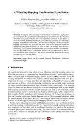
Basic Motion Capture Architecture<br />
The most basic <strong>Vicon</strong> <strong>MX</strong> architecture consists of from one-eight<br />
<strong>MX</strong> cameras, an <strong>MX</strong> Ultranet, and the host PC (for descriptions of<br />
these system elements, see <strong>Vicon</strong> <strong>MX</strong> Architecture Elements on<br />
page 1-1). This basic architecture is illustrated in Figure 1-1.<br />
Figure 1-1: Basic <strong>Vicon</strong> <strong>MX</strong> architecture<br />
<strong>Vicon</strong> <strong>MX</strong> <strong>Hardware</strong> <strong>System</strong> <strong>Reference</strong> 1-3
Introduction<br />
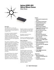
Large Camera-Count Architecture<br />
If your application requires more than eight <strong>MX</strong> cameras, you must<br />
include additional <strong>MX</strong> Ultranet units in the <strong>Vicon</strong> <strong>MX</strong> architecture. If<br />
your system has an <strong>MX</strong> Net unit, you must include additional <strong>MX</strong> Net<br />
units along with <strong>MX</strong> Link units to connect these together. For<br />
descriptions of these system elements, see <strong>Vicon</strong> <strong>MX</strong> Architecture<br />
Elements on page 1-1. This large camera-count architecture is<br />
illustrated in Figure 1-2.<br />
Figure 1-2: <strong>Vicon</strong> <strong>MX</strong> architecture with 40 cameras and 5 <strong>MX</strong> Ultranet units<br />
1-4 <strong>Vicon</strong> <strong>MX</strong> <strong>Hardware</strong> <strong>System</strong> <strong>Reference</strong>
Integrated Third-party Application Architecture<br />
Introduction<br />
If your application integrates third-party analog capture, genlock, and<br />
timecode devices, you must include an <strong>MX</strong> Control, with the<br />
appropriate option card installed, in the <strong>Vicon</strong> <strong>MX</strong> architecture. If you<br />
require an extended interface to the GPIO (general purpose input<br />
output) or remote control functionality available in the <strong>MX</strong> Control or<br />
<strong>MX</strong> Ultranet, you can include an <strong>MX</strong> Sync between that <strong>MX</strong> unit and<br />
the third-party device. For descriptions of these system elements, see<br />
<strong>Vicon</strong> <strong>MX</strong> Architecture Elements on page 1-1. This integrated thirdparty<br />
application architecture is illustrated in Figure 1-3.<br />
Figure 1-3: <strong>Vicon</strong> <strong>MX</strong> architecture with <strong>MX</strong> Control and third-party device<br />
<strong>Vicon</strong> <strong>MX</strong> <strong>Hardware</strong> <strong>System</strong> <strong>Reference</strong> 1-5
Introduction<br />
Integrated V-series Cameras Architecture<br />
If your application integrates <strong>Vicon</strong> MCam2, VCam, SVCam,<br />
MCam(PAL), or MCam(NTSC) cameras supported previously by <strong>Vicon</strong><br />
V-series systems, you must include an <strong>MX</strong> Bridge in the <strong>Vicon</strong> <strong>MX</strong><br />
architecture (for descriptions of these system elements, see <strong>Vicon</strong> <strong>MX</strong><br />
Architecture Elements on page 1-1). This integrated V-series<br />
cameras architecture is illustrated in Figure 1-4.<br />
Figure 1-4: <strong>Vicon</strong> <strong>MX</strong> architecture with <strong>MX</strong> Bridge and V-series cameras<br />
1-6 <strong>Vicon</strong> <strong>MX</strong> <strong>Hardware</strong> <strong>System</strong> <strong>Reference</strong>
2<strong>MX</strong> Bridge<br />
<strong>Vicon</strong> <strong>MX</strong> <strong>Hardware</strong> <strong>System</strong> <strong>Reference</strong> 2-1<br />
2<br />
This chapter describes the physical structure of the <strong>MX</strong> Bridge,<br />
including its connections to other <strong>Vicon</strong> <strong>MX</strong> components and to<br />
supported V-series cameras.<br />
The <strong>MX</strong> Bridge provides the interface between <strong>Vicon</strong> <strong>MX</strong> and any<br />
MCam2, VCam, SVCam, MCam(PAL), and MCam(NTSC) cameras<br />
supported previously by <strong>Vicon</strong> V-series systems. It acts like an <strong>MX</strong><br />
emulator and transforms the images sent by these cameras to the<br />
grayscale format used in <strong>Vicon</strong> <strong>MX</strong>.<br />
The <strong>MX</strong> Bridge is optional in <strong>Vicon</strong> <strong>MX</strong>. It connects to an <strong>MX</strong> Ultranet<br />
or an <strong>MX</strong> Net in the same way as an <strong>MX</strong> camera, with the same<br />
physical connector, cables, and signals. An <strong>MX</strong> Bridge can connect up<br />
to three V-series cameras of the same type to the <strong>Vicon</strong> <strong>MX</strong> system.<br />
You can add additional <strong>MX</strong> Bridges to your <strong>Vicon</strong> <strong>MX</strong> architecture to<br />
meet your needs.<br />
Important<br />
Apart from VCam and SVCam cameras, which are interchangeable, you<br />
cannot connect a combination of other camera types to a single <strong>MX</strong> Bridge.<br />
If you want to integrate multiple V-series camera types in your <strong>Vicon</strong> <strong>MX</strong><br />
system, you must use separate <strong>MX</strong> Bridge units for each camera type.<br />
The <strong>MX</strong> Bridge is a 1U unit that can be rack-, wall-, or floor-mounted<br />
and stacked either horizontally or vertically.<br />
<strong>MX</strong> Bridge Front Panel<br />
Figure 6-1 illustrates the front panel of the <strong>MX</strong> Bridge.<br />
Figure 2-1: <strong>MX</strong> Bridge front panel
<strong>MX</strong> Bridge<br />
A group of six LED status indicators on the front panel provide<br />
feedback on the status of each of the three camera channels (camera<br />
channels 1-3 from left to right of the front panel). Within this group<br />
of six LED status indicators are the following:<br />
• <strong>MX</strong> Ethernet Network Status Lights<br />
The vertically aligned status lights are green LEDs for standard<br />
Ethernet status indicators (from top to bottom):<br />
• Tx – Transmit<br />
LED is lit when the <strong>MX</strong> Ethernet network is capable of<br />
transmitting data.<br />
• Rx – Receive<br />
LED flashes when receiving data and communications from the<br />
<strong>MX</strong> Ethernet network. The frequency of the flashes varies with<br />
the amount of network traffic.<br />
• Col – Collision<br />
LED flashes if a network collision occurs on the <strong>MX</strong> Ethernet<br />
network.<br />
• Camera Status Indicators<br />
The horizontally aligned camera status lights provide feedback on<br />
the status of the camera and its state within the <strong>Vicon</strong> software<br />
on the host PC.<br />
After the camera is connected, the camera status lights provide<br />
the following information (from left to right):<br />
• Yellow<br />
LED indicating the camera’s enabled state in the <strong>Vicon</strong><br />
software:<br />
On: Disabled by the software (e.g. the RealTime<br />
Engine has been started, but this camera is not<br />
included in the current calibration).<br />
Off: Not disabled by the software.<br />
• Green<br />
LED indicating the camera’s connection state in the <strong>Vicon</strong><br />
software:<br />
On: Connected and sending data.<br />
2-2 <strong>Vicon</strong> <strong>MX</strong> <strong>Hardware</strong> <strong>System</strong> <strong>Reference</strong>
<strong>MX</strong> Bridge<br />
• Blue<br />
LED indicating the camera’s selection state in the <strong>Vicon</strong><br />
software:<br />
<strong>MX</strong> Bridge Rear Panel<br />
Flashing: Connected but not currently sending data.<br />
Off: Not connected.<br />
On: Selected.<br />
Flashing: Selected as primary.<br />
Off: Not selected.<br />
Figure 6-2 illustrates the rear panel of the <strong>MX</strong> Bridge.<br />
Figure 2-2: <strong>MX</strong> Bridge rear panel<br />
The rear panel contains the following controls and connection points<br />
(from left to right of the rear panel):<br />
• Camera Select<br />
Rotary dial to configure the <strong>MX</strong> Bridge for a particular <strong>Vicon</strong><br />
camera type:<br />
• 13: MCam2<br />
• 14: VCam/SVCam<br />
• 5: MCam(PAL)<br />
• 6: MCam(NTSC)<br />
For details on these V-series cameras, see Supported Camera<br />
Modes on page 2-4.<br />
<strong>Vicon</strong> <strong>MX</strong> <strong>Hardware</strong> <strong>System</strong> <strong>Reference</strong> 2-3
<strong>MX</strong> Bridge<br />
• Analog Camera<br />
Three sets of connectors for camera channels 1, 2, and 3:<br />
• 12-pin Lemo socket for connecting to an MCam2, VCam,<br />
SVCam, MCam(PAL), or MCam(NTSC) camera.<br />
• BNC socket located to the right of the 12-pin Lemo connector<br />
for connecting to an MCam camera.<br />
Warning<br />
Do not use the 12-pin Lemo socket to connect an <strong>MX</strong> Bridge unit to either an<br />
<strong>MX</strong> Net unit or an <strong>MX</strong> Link unit. Plugging one end of a 12-pin Lemo plug into<br />
an Analog Camera socket on the rear panel of an <strong>MX</strong>-Bridge and the other<br />
end of the plug into either the Link Connect socket on the rear panel of an<br />
<strong>MX</strong> Link or the Link socket on the rear panel of an <strong>MX</strong> Net will result in<br />
damage to the units.<br />
• Net Connect<br />
10-Pin Lemo socket located to the right of each set of Analog<br />
Camera connectors. This connects the <strong>MX</strong> Bridge to an<br />
<strong>MX</strong> Ultranet or an <strong>MX</strong> Net, which supplies power and<br />
synchronization to each connected camera and carries the signal<br />
to and from it. For details on these other <strong>MX</strong> units, see<br />
Chapter 7 <strong>MX</strong> Net and Chapter 9 <strong>MX</strong> Ultranet. For details on the<br />
<strong>MX</strong> Ultranet—<strong>MX</strong> Bridge cable and <strong>MX</strong> Net—<strong>MX</strong> Bridge cables,<br />
see Chapter 11 <strong>MX</strong> Cables.<br />
• External Interface<br />
9-pin D-type RS-232 serial socket. This provides an interface to<br />
the cameras connected to the <strong>MX</strong> Bridge and is typically used only<br />
for factory test purposes.<br />
Supported Camera Modes<br />
Camera-specific cabling connects the supported <strong>Vicon</strong> cameras to the<br />
<strong>MX</strong> Bridge camera channel inputs (for details, see Chapter 11 <strong>MX</strong><br />
Cables). The <strong>MX</strong> Bridge unit is configured to identify the connected<br />
camera type and pass this information to the <strong>Vicon</strong> application<br />
software on the host PC.<br />
The following sections give the performance details for the V-series<br />
cameras that can be connected to <strong>Vicon</strong> <strong>MX</strong> through an <strong>MX</strong> Bridge:<br />
• MCam2<br />
• VCam<br />
• SVCam<br />
2-4 <strong>Vicon</strong> <strong>MX</strong> <strong>Hardware</strong> <strong>System</strong> <strong>Reference</strong>
<strong>MX</strong> Bridge<br />
• MCam(PAL) for PAL video systems<br />
• MCam(NTSC) for NTSC video systems<br />
<strong>MX</strong> Bridge supports only the camera frame rates supported by the<br />
camera itself. All supported frame rates are progressive scan. In all<br />
cases the Camera Select dial on the rear panel of the <strong>MX</strong> Bridge<br />
must be set to the indicated setting for the camera type (for details<br />
on this control, see <strong>MX</strong> Bridge Rear Panel on page 2-3). You can<br />
specify the frame rates for each camera in the <strong>Vicon</strong> software. The<br />
actual frame rates you can specify depends on the <strong>Vicon</strong> software you<br />
are using. For details, see your software documentation.<br />
MCam2 Cameras<br />
Warning<br />
Before adjusting the Camera Select dial on the rear of the <strong>MX</strong> Bridge, you<br />
must first disconnect the <strong>MX</strong> Bridge unit from the <strong>Vicon</strong> <strong>MX</strong> system. Failure<br />
to do so could result in damage to the camera.<br />
For further details on these cameras, see the hardware user manual<br />
for your V-series system or <strong>Vicon</strong> Online Support (VOS). For details<br />
on obtaining information from VOS, see Appendix G Support<br />
Resources.<br />
Table 2-1 illustrates the performance of a <strong>Vicon</strong> MCam2 camera in a<br />
<strong>Vicon</strong> <strong>MX</strong> system. The Camera Select dial on the rear panel of the<br />
<strong>MX</strong> Bridge must be set to 13 for MCam2 cameras.<br />
Table 2-1: MCam2 camera performance<br />
Performance Frame Rate (fps)<br />
59.94 100 119.88<br />
Resolution (pixels) 1272 H x 1024 V 1266 H x 1024 V 1266 H x 940 V<br />
Aspect Ratio 5:4 5:4 4:3<br />
Usable sensor size (mm) 15.26 h x 15.19 h x 15.19 h x<br />
12.29 v<br />
12.29 v<br />
11.28 v<br />
Shuttered Yes Yes Yes<br />
Sensor Type CMOS CMOS CMOS<br />
250 500 1000<br />
Resolution (pixels) 816 H x 656 V 498 H x 480 V 498 H x 210 V<br />
Aspect Ratio 5:4 1:1 5:2<br />
Usable sensor size (mm) 9.79 h x 7.87 v 5.97 h x 5.76 v 5.97 h x 2.52 v<br />
<strong>Vicon</strong> <strong>MX</strong> <strong>Hardware</strong> <strong>System</strong> <strong>Reference</strong> 2-5
<strong>MX</strong> Bridge<br />
Performance Frame Rate (fps)<br />
59.94 100 119.88<br />
Shuttered Yes Yes Yes<br />
Sensor Type CMOS CMOS CMOS<br />
In <strong>Vicon</strong> <strong>MX</strong>, you can control the intensity of the image from a <strong>Vicon</strong><br />
camera using the Gain slider in the <strong>Vicon</strong> application software. The<br />
software Gain slider can be set to a factor of 1-4.<br />
When using an MCam2 camera connected through an <strong>MX</strong> Bridge, you<br />
can also use the Control dial on the rear panel of the camera to set<br />
the camera gain. The camera Control dial can be set to Low, Medium,<br />
or High gain settings, which are equivalent to factors 1, 2, and 3 on<br />
the software Gain slider.<br />
In <strong>Vicon</strong> <strong>MX</strong>, these settings work in series, so the camera gain setting<br />
is multiplied by the software gain factor. For example, if you set the<br />
camera gain setting to 2 and then set the software gain factor to 2,<br />
the total gain is 4. The maximum total gain must not exceed a value<br />
of 4.<br />
VCam/SVCam Cameras<br />
Table 2-1: MCam2 camera performance<br />
Table 2-2 illustrates the performance of a <strong>Vicon</strong> VCam/ SVCam<br />
camera in a <strong>Vicon</strong> <strong>MX</strong> system. The Camera Select dial on the rear<br />
panel of the <strong>MX</strong> Bridge must be set to 14 for VCam/SVCam cameras.<br />
Table 2-2: VCam/SVCam camera performance<br />
Performance Frame Rate (fps)<br />
Resolution (pixels) 648 H x<br />
493 V<br />
100 119.88 150 200<br />
648 H x<br />
493 V<br />
648 H x<br />
493 V<br />
Aspect Ratio 4:3 4:3 4:3 4:3<br />
Usable sensor size<br />
(mm)<br />
6.42 h x<br />
4.88 v<br />
6.42 h x<br />
4.88 v<br />
6.42 h x<br />
4.88 v<br />
648 H x<br />
493 V<br />
6.42 h x<br />
4.88 v<br />
Shuttered Yes Yes Yes Yes<br />
Sensor Type CMOS CMOS CMOS CMOS<br />
2-6 <strong>Vicon</strong> <strong>MX</strong> <strong>Hardware</strong> <strong>System</strong> <strong>Reference</strong>
MCam(PAL) Cameras<br />
<strong>MX</strong> Bridge<br />
Table 2-3 illustrates the performance of a <strong>Vicon</strong> MCam(PAL) camera<br />
for PAL video systems in a <strong>Vicon</strong> <strong>MX</strong> system. The Camera Select dial<br />
on the rear panel of the <strong>MX</strong> Bridge must be set to 5 for MCam(PAL)<br />
cameras.<br />
MCam(NTSC) Cameras<br />
Table 2-3: MCam(PAL) camera performance<br />
Performance Frame Rate (fps)<br />
50 100<br />
Resolution (pixels) 1011 H x 1024 V 1000 H x 972 V<br />
Aspect Ratio 1:1 1:1<br />
Usable sensor size (mm) 10.11 h x 10.24 v 10.00 h x 9.72 v<br />
Shuttered No No<br />
Sensor Type CMOS CMOS<br />
Table 2-4 illustrates the performance of a <strong>Vicon</strong> MCam(NTSC) camera<br />
for NTSC video systems in a <strong>Vicon</strong> <strong>MX</strong> system. The Camera Select<br />
dial on the rear panel of the <strong>MX</strong> Bridge must be set to 6 for<br />
MCam(NTSC) cameras.<br />
Table 2-4: MCam(NTSC) camera performance<br />
Performance Frame Rate (fps)<br />
59.94 119.88<br />
Resolution (pixels) 1012 H x 987 V 947 H x 881 V<br />
Aspect Ratio 1:1 1:1<br />
Usable sensor size (mm) 10.12 h x 9.87 v 9.47 h x 8.81 v<br />
Shuttered No No<br />
Sensor Type CMOS CMOS<br />
<strong>Vicon</strong> <strong>MX</strong> <strong>Hardware</strong> <strong>System</strong> <strong>Reference</strong> 2-7
<strong>MX</strong> Bridge<br />
2-8 <strong>Vicon</strong> <strong>MX</strong> <strong>Hardware</strong> <strong>System</strong> <strong>Reference</strong>
Camera Types<br />
3<strong>MX</strong> Cameras<br />
This chapter describes the <strong>MX</strong>+ and <strong>MX</strong> cameras, including<br />
associated strobe units, connectors, and cables.<br />
Warning<br />
There are no internal operator adjustments inside any components of the<br />
<strong>MX</strong> cameras. Refer servicing to qualified personnel.<br />
<strong>Vicon</strong> <strong>MX</strong> <strong>Hardware</strong> <strong>System</strong> <strong>Reference</strong> 3-1<br />
3<br />
<strong>Vicon</strong> <strong>MX</strong> has a single camera hardware design that consists of a<br />
distinct video camera, a strobe head unit, a suitable lens, optical filter,<br />
and cables as shown in Figure 3-1.<br />
Figure 3-1: <strong>Vicon</strong> <strong>MX</strong>+ camera and <strong>Vicon</strong> <strong>MX</strong> camera<br />
This single hardware design can be built with different types of sensor<br />
and strobe units to create a range of <strong>MX</strong>+ and <strong>MX</strong> cameras with<br />
different resolutions:<br />
• <strong>MX</strong>40+ and <strong>MX</strong>40 (4 Megapixels)<br />
• <strong>MX</strong>20+ (2 Megapixels)<br />
• <strong>MX</strong>13+ and <strong>MX</strong>13 (1.3 Megapixels)<br />
• <strong>MX</strong>3+ and <strong>MX</strong>3 (0.3 Megapixels)<br />
Important<br />
If you are integrating <strong>Vicon</strong> MCam2, VCam, SVCam, MCam(PAL), or<br />
MCam(NTSC) cameras supported previously by <strong>Vicon</strong> V-series systems, see<br />
Chapter 2 <strong>MX</strong> Bridge for details on those cameras.
<strong>MX</strong> Cameras<br />
All cameras are high-quality devices, fitted with sensitive solid-state<br />
sensors. <strong>Vicon</strong> Motion <strong>System</strong>s subjects its cameras to stringent<br />
checks for linearity, sensitivity, and absence of jitter.<br />
All <strong>MX</strong> cameras provide high-speed and low-latency motion capture.<br />
You can combine the different types of <strong>MX</strong> camera within a single<br />
<strong>Vicon</strong> <strong>MX</strong> system to meet your application requirements for resolution<br />
and/or coverage. The <strong>MX</strong>40+ and <strong>MX</strong>40 cameras offer the highest<br />
resolution of the <strong>MX</strong> cameras. The <strong>MX</strong>3+ and <strong>MX</strong>3 cameras can<br />
provide higher camera counts within a fixed budget, giving increased<br />
coverage.<br />
Each <strong>MX</strong> camera is programmed with firmware to control its operation<br />
and enable it to perform its own onboard grayscale processing. As all<br />
<strong>MX</strong> cameras use the same firmware, a mixture of cameras with<br />
different image sensors can be connected to and run on the same<br />
<strong>Vicon</strong> <strong>MX</strong> system. <strong>Vicon</strong> <strong>MX</strong> automatically recognizes cameras and<br />
their relevant characteristics when they are plugged in. <strong>Vicon</strong> <strong>MX</strong>’s<br />
distributed architecture enables the camera software to be updated<br />
across the system network.<br />
Table 3-1 illustrates the performance of each <strong>MX</strong> camera type.<br />
<strong>MX</strong>40+ /<br />
Performance<br />
<strong>MX</strong>40<br />
Resolution (pixels) 2352 H x<br />
1728 V<br />
Maximum Frame<br />
Rate (fps) at full<br />
resolution<br />
Table 3-1: <strong>MX</strong> camera performance<br />
<strong>MX</strong>20+<br />
1600 H x<br />
1280 V<br />
<strong>MX</strong>13+ /<br />
<strong>MX</strong>13<br />
1280 H x<br />
1024 V<br />
160 219 482 242<br />
<strong>MX</strong>3+ /<br />
<strong>MX</strong>3<br />
659 H x<br />
494 V<br />
Aspect Ratio 4:3 5:4 5:4 4:3<br />
Sensor Size<br />
(Megapixels)<br />
4 2 1.3 0.3<br />
Sensor size (mm) 16.5 h x 11.20 h x 15.4 h x 6.5 h x<br />
12.1 v 8.96 v 12.3 v 4.9 v<br />
Shuttered No No Yes Yes<br />
Sensor Type CMOS CMOS CMOS CMOS<br />
VGA Monitor Mode 85.1 kHz h x Not Available 60 kHz h x 60 kHz h x<br />
48 Hz v<br />
50 Hz v 100 Hz v<br />
3-2 <strong>Vicon</strong> <strong>MX</strong> <strong>Hardware</strong> <strong>System</strong> <strong>Reference</strong>
<strong>MX</strong> Cameras<br />
Performance Notes:<br />
• Shuttering: The image quality from a shuttered camera is<br />
constant across all frame rates. For an unshuttered camera, which<br />
is more susceptible to background light levels, narrow bandwidth<br />
interference filters are used to provide a signal to noise ratio<br />
performance comparable to the shuttered cameras. Factors such<br />
as strobe illumination, field of view, and depth of field also affect<br />
the image quality. For details of which cameras are shuttered or<br />
not, see Table 3-1 on page 3-2. For further details on how to work<br />
with these factors, see Camera Lenses on page 3-4.<br />
• Monitor Mode: The camera frame rate that monitor mode runs<br />
at is fixed. This mode enables you to use a VGA monitor as a view<br />
finder for the camera; motion capture is not performed in this<br />
mode. For details, see VGA Monitor (<strong>MX</strong>+ and <strong>MX</strong>) on page 3-12.<br />
• Increased Frame Rates: You can specify higher frame rates<br />
than those shown in Table 3-1 on page 3-2. However, at higher<br />
frequencies, the <strong>MX</strong> cameras automatically reduce the image size<br />
(vertical windowing). For details, see Field of View on page 3-4.<br />
You can specify the capture frame rate of each <strong>MX</strong> camera in the<br />
<strong>Vicon</strong> software. <strong>MX</strong> cameras are capable of capturing up to a<br />
maximum of 2,000 fps, but the actual frame rate you can specify<br />
depends on the <strong>Vicon</strong> application software you are using. For<br />
details, see your software documentation.<br />
• Grayscale Precision: <strong>MX</strong> cameras evaluate an entire image in<br />
grayscale, rather than applying a black and white threshold. This<br />
provides more information and increases motion measurement<br />
accuracy over an equivalent resolution black and white camera.<br />
The <strong>MX</strong> cameras perform the majority of data processing. They<br />
generate grayscale blobs for reflections from objects in the capture<br />
volume and then use centroid-fitting algorithms to determine<br />
which of these objects are likely to be markers. <strong>MX</strong> camera data<br />
is sent to <strong>Vicon</strong> application software for viewing and further processing.<br />
For details, see your software documentation.<br />
• Bandwidth: Even with the elimination of background grayscale<br />
through thresholding, <strong>MX</strong> performance will be limited in real time<br />
by the number of cameras, number of markers, and the frame<br />
rate. <strong>MX</strong> data capture to disk is limited by the time it takes to write<br />
the data to disk as no buffering outside the host PC is available.<br />
You can configure the buffering of <strong>MX</strong> data at the time of capture.<br />
You do this in the <strong>Vicon</strong> software on the host PC. For details, see<br />
<strong>Vicon</strong> <strong>MX</strong> <strong>Hardware</strong> <strong>System</strong> <strong>Reference</strong> 3-3
<strong>MX</strong> Cameras<br />
Camera Lenses<br />
Field of View<br />
the software documentation.<br />
• Synchronization: Cameras are automatically assigned master<br />
(controlling device) or subordinate (controlled device) status.<br />
Each <strong>Vicon</strong> <strong>MX</strong> system has only one master device, which provides<br />
the synchronization to the rest of the system and is established<br />
automatically during system booting. The master device is an<br />
<strong>MX</strong> Camera, or an <strong>MX</strong> Ultranet if present, or an <strong>MX</strong> Control if<br />
present. For details on system synchronization by the <strong>MX</strong> Control,<br />
see Chapter 4 <strong>MX</strong> Control.<br />
The function of the camera lens is to collect reflected light from a<br />
scene and form a focused image on the camera’s sensor plane. The<br />
type of lens that will provide optimum performance for a particular<br />
application depends on various factors, including the field of view<br />
(FOV), the aperture, and any lens filter fitted.<br />
Important<br />
<strong>Vicon</strong> Motion <strong>System</strong>s has a policy of only using the best quality lenses with<br />
its cameras. Should you need to change lenses, please refer to <strong>Vicon</strong> Motion<br />
<strong>System</strong>s or your nearest agent or distributor for advice.<br />
A variety of small and large format C-mount lenses as well as SLR<br />
(Nikon Bayonet) lenses are available for <strong>MX</strong> cameras. For details on<br />
<strong>MX</strong> camera specifications, see Appendix D Technical Specifications.<br />
The most important factor in determining the lens to use with a<br />
<strong>Vicon</strong> <strong>MX</strong> camera is the total area the camera can see using a given<br />
lens. This is called the Field of View (FOV).<br />
The scene that comprises the FOV has horizontal width (H) and<br />
vertical height (V). Knowing the distance (L) between the camera and<br />
a plane that defines the total FOV helps to select the type of lens to<br />
meet a particular application.<br />
Lenses are described in terms of their focal length (f), defined as the<br />
distance in millimeters that the center of the lens must be from the<br />
sensor plane surface to project a sharp image on the sensor. The focal<br />
length of a lens is often given on the body of the lens or around the<br />
surround of the glass element at the front of the lens as well as on<br />
the lens documentation and packaging.<br />
3-4 <strong>Vicon</strong> <strong>MX</strong> <strong>Hardware</strong> <strong>System</strong> <strong>Reference</strong>
<strong>MX</strong> Cameras<br />
The focal length determines the angle of view (AOV) through the lens,<br />
as shown in Figure 3-2.<br />
Figure 3-2: Angle of View calculation<br />
Normally, the AOV is calculated based on the known focal length and<br />
sensor size. This in turn determines the FOV, based on the distance<br />
(L) to the object being captured. Figure 3-3 illustrates how the FOV<br />
is calculated.<br />
Figure 3-3: Field of View calculation<br />
<strong>Vicon</strong> <strong>MX</strong> <strong>Hardware</strong> <strong>System</strong> <strong>Reference</strong> 3-5
<strong>MX</strong> Cameras<br />
The sensor area used for capturing data through each <strong>MX</strong> camera<br />
determines the maximum FOV available for a particular combination<br />
of camera and lens. The area of the sensor is determined by its<br />
horizontal width (h) and vertical height (v).<br />
The capture frame rate for each <strong>MX</strong> camera can be configured in the<br />
<strong>Vicon</strong> application software (for details, see the software<br />
documentation). The configured frame rate will also affect the field<br />
of view. Higher camera frame rates may make vertical windowing of<br />
the sensor necessary such that the sensor area used for capture is<br />
reduced in comparison to lower camera frame rates.<br />
Another characteristic of the camera sensor is the image circle. This<br />
is the sharp circular image that the camera lens casts onto the sensor,<br />
as shown in Figure 3-4.<br />
Figure 3-4: Image circle<br />
The diameter of this image circle is the maximum area of usable<br />
quality image that the lens can produce. Most lenses produce their<br />
best image at the center of the lens, dropping off in performance<br />
towards the outer extremes of the lens. This results in a gradual<br />
darkening of the image towards the corners of the image, known as<br />
vignetting. Theoretically, vignetting gets worse for wider angle lenses<br />
and for wider open apertures, but the area at which vignetting starts<br />
to occur depends on the lens.<br />
Thus for optimum performance, the image circle projected should be<br />
larger than the sensor area used by the camera. This ensures that the<br />
entire sensor is utilized and eliminates the fall-off of light that occurs<br />
towards the edge of the image circle. If the image circle of a lens is<br />
too small for the sensor size, then the camera image around the edges<br />
3-6 <strong>Vicon</strong> <strong>MX</strong> <strong>Hardware</strong> <strong>System</strong> <strong>Reference</strong>
<strong>MX</strong> Cameras<br />
and corners is lost. <strong>MX</strong> cameras are fitted with lenses that have an<br />
appropriately sized image circle for the sensor.<br />
If you wish to change the supplied lens, you must consider the sensor<br />
size of the new lens. Even if the focal length of the new lens is the<br />
same, a different sensor size will produce a different field of view. For<br />
example, the sensor sizes of C-Mount lenses are specified in formats<br />
of 1”, 2/3”, 1/2”, 1/3”, and 1/4”, which reflect a ratio of<br />
1:0.69:0.5:0.38:0.25. Thus, a 1/2” format is 50% of a 1" format, a<br />
1/3” format is 75% of a 1/2” format, and so on. For guidance on the<br />
necessary image circle diameter for a specific sensor format, see<br />
details on the <strong>MX</strong> camera lens specifications in Appendix D Technical<br />
Specifications.<br />
Table 3-2 gives the formulae used to calculate the angle of view (AOV)<br />
and field of view (FOV) for camera and lens combinations. These<br />
formulae require the dimensions of the sensor area used for each of<br />
the <strong>MX</strong> cameras at different frequencies.<br />
Horizontal<br />
AOV (°)<br />
Table 3-2: AOV and FOV formulae<br />
Vertical<br />
AOV (°)<br />
Horizontal<br />
FOV<br />
Width H (m)<br />
2 x Tan -1 (h/2f) 2 x Tan -1 (v/2f) h x L/f v x L/f<br />
Vertical<br />
FOV<br />
Height V (m)<br />
where:<br />
f = focal length of the lens (mm)<br />
h = horizontal width of sensor (mm) (see Sensor size entry in<br />
Table 3-1 on page 3-2)<br />
v = vertical height of sensor (mm) (see Sensor size entry in<br />
Table 3-1 on page 3-2)<br />
L = distance from the lens to the object (m)<br />
As an example, consider an <strong>MX</strong>40+ camera with a 20 mm lens<br />
operating at 160 Hz at a distance of 9 m from the target markers:<br />
• Horizontal AOV would be:<br />
2 x Tan-1 (16.5/40) = 44.8 °<br />
• Vertical AOV would be:<br />
2 x Tan -1 (12.1/40) = 33.7 °<br />
<strong>Vicon</strong> <strong>MX</strong> <strong>Hardware</strong> <strong>System</strong> <strong>Reference</strong> 3-7
<strong>MX</strong> Cameras<br />
• Horizontal FOV at 9m would be:<br />
16.5 x (9/20) = 7.43 m<br />
• Vertical FOV at 9m would be:<br />
12.1 x (9/20) = 5.44 m<br />
Important<br />
These formulae take into account only the optical components of the camera<br />
and lens, thus they calculate the maximum possible theoretical Field of View<br />
from this combination. Poor illumination of the volume by camera strobes,<br />
less than optimal aperture or gain settings, or poor marker surface quality<br />
might all reduce the FOV in which a camera can recognize a marker below<br />
this maximum theoretical level.<br />
Please note when using these formulae that frequencies above the fullresolution<br />
frequencies given in Table 3-1 on page 3-2, the sensor area is<br />
reduced due to vertical windowing, as described in Field of View on page 3-4.<br />
Aperture and Depth of Field<br />
Another significant factor in choosing a lens type is the aperture (also<br />
known as the f-stop value, f-number, and F#), which refers to the<br />
speed with which the lens can pass light in a given time.<br />
The aperture is the ratio of the focal length of the lens to the diameter<br />
of the lens opening, which determines the amount of light that can<br />
pass through the lens in a given time. Smaller f-stop values (e.g. f2,<br />
f2.8) represent wider apertures that allow more light to pass through,<br />
while larger f-stop values (e.g. f11, f16, f22) represent narrower<br />
apertures that allow less light to pass through. Typically, faster lenses<br />
have larger diameter optics that can pass more light.<br />
Each f-stop value changes the lens opening from the next f-stop by<br />
a factor of 2. For example, decreasing the aperture from f11 to f8<br />
allows twice as much light to pass through. Increasing the aperture<br />
from f11 to f16 allows half as much light to pass through.<br />
The aperture and magnification affect the depth of field, that is, the<br />
portion of the image that has sharp focus. Immediately surrounding<br />
this area, there is a region in which the image remains in focus.<br />
Outside of this area, moving towards or away from the lens, the focus<br />
becomes progressively less sharp and the image appears out of focus.<br />
Thus, as the aperture and focal length decrease, the depth of field<br />
increases. Conversely, as the aperture and focal length increase, the<br />
depth of field decreases.<br />
3-8 <strong>Vicon</strong> <strong>MX</strong> <strong>Hardware</strong> <strong>System</strong> <strong>Reference</strong>
Camera Lens Filters<br />
<strong>MX</strong> Cameras<br />
In order to optimize the performance of the <strong>MX</strong> cameras, each lens<br />
is fitted with an optical filter to attenuate wavelengths of light other<br />
than those emitted by the light emitting diodes (LEDs) in the <strong>MX</strong><br />
strobe unit and reflected back from the markers to the camera.<br />
Shuttered <strong>MX</strong> cameras (see Table 3-1 on page 3-2) are less<br />
susceptible to interference from background light levels. These<br />
cameras are fitted as standard with low-pass absorptive filters<br />
(allowing low-frequency light to pass) appropriate for each of the<br />
Visible Red (VR), Near Infrared (NIR), and Infrared (IR) strobe units<br />
available (for details, see Camera Strobe Units on page 3-14).<br />
Unshuttered <strong>MX</strong> cameras (see Table 3-1 on page 3-2) are potentially<br />
more susceptible to background light. Therefore, a more restrictive<br />
band-pass interference filter is fitted as standard to the these<br />
cameras, appropriate for each of the VR, NIR, and IR strobe units<br />
available. When using an unshuttered <strong>MX</strong> camera under wellcontrolled<br />
lighting conditions, it may be appropriate to replace this<br />
band-pass interference filter with a low-pass absorptive filter to<br />
maximize the amount of strobe light returned to the camera sensor.<br />
Camera Controls and Connectors<br />
This section describes the physical structure of <strong>Vicon</strong> <strong>MX</strong> cameras and<br />
the connections and cables that are used to connect them to other<br />
system components.<br />
<strong>Vicon</strong> <strong>MX</strong> cameras have been designed to consolidate all video and<br />
strobe functions in a single unit and to automatically set strobe<br />
durations and video frame rates directly from the <strong>Vicon</strong> software on<br />
the host PC.<br />
<strong>Vicon</strong> <strong>MX</strong> <strong>Hardware</strong> <strong>System</strong> <strong>Reference</strong> 3-9
<strong>MX</strong> Cameras<br />
<strong>MX</strong>+ and <strong>MX</strong> Camera Rear Panels<br />
Figure 3-5 shows the camera controls on the rear panel of an<br />
<strong>MX</strong>+ camera.<br />
Figure 3-5: <strong>MX</strong>+ Camera rear panel<br />
3-10 <strong>Vicon</strong> <strong>MX</strong> <strong>Hardware</strong> <strong>System</strong> <strong>Reference</strong>
Figure 3-6 shows the camera controls on the rear panel of an<br />
<strong>MX</strong> camera.<br />
Figure 3-6: <strong>MX</strong> Camera rear panel<br />
<strong>MX</strong> Cameras<br />
The rear panel contains the following controls and connection points<br />
(differences between <strong>MX</strong>+ and <strong>MX</strong> cameras are identified):<br />
• <strong>System</strong> (<strong>MX</strong>+)<br />
9-pin D-type RS-232 Serial Interface and power. This is reserved<br />
for <strong>Vicon</strong> production and testing; no customer connections are<br />
required.<br />
• External Interface (<strong>MX</strong>)<br />
4-Pin Lemo RS-232 Serial Interface and power. This is reserved<br />
for <strong>Vicon</strong> production and testing; no customer connections are<br />
required.<br />
<strong>Vicon</strong> <strong>MX</strong> <strong>Hardware</strong> <strong>System</strong> <strong>Reference</strong> 3-11
<strong>MX</strong> Cameras<br />
• VGA Monitor (<strong>MX</strong>+ and <strong>MX</strong>)<br />
15-pin VGA connector for fixed-frequency output to a VGA<br />
monitor. The VGA monitor must be able to display the range of<br />
frequencies listed in the entry for the VGA Monitor Mode entry in<br />
Table 3-1 on page 3-2.<br />
A VGA monitor was used in <strong>Vicon</strong> V-series systems primarily for<br />
focusing an individual camera on an object other than a marker.<br />
In <strong>Vicon</strong> <strong>MX</strong> systems, focusing is typically done while viewing<br />
grayscale data for markers in the <strong>Vicon</strong> application software: for<br />
example in a Live Monitor window (and optionally Preview mode)<br />
in Workstation, or in a Camera view pane or a Fullscreen Preview<br />
view pane in <strong>Vicon</strong> Nexus and <strong>Vicon</strong> iQ. You can zoom in on an<br />
image viewed through the Live Monitor or a Camera view pane,<br />
which you cannot do with a VGA monitor.<br />
The <strong>MX</strong> cameras automatically start in monitor mode during<br />
system boot up, but switch this mode off once connected to the<br />
<strong>Vicon</strong> application software. If you wish to use this VGA Monitor<br />
connector, you must either:<br />
• Ensure that the cameras are not connected to the <strong>Vicon</strong><br />
application software during system start up.<br />
• Manually switch on monitor mode from the <strong>Vicon</strong> application<br />
software.<br />
Once monitor mode is switched on, the <strong>MX</strong> camera automatically<br />
changes its frame rate to match that in Table 3-1 on page 3-2 and<br />
starts sending data to the connected VGA monitor. The camera<br />
remains in this mode until you either manually switch off monitor<br />
mode or reboot the camera from the <strong>Vicon</strong> application software.<br />
If you fail to switch off monitor mode, the frame rate of this<br />
camera may be out of synch with other <strong>MX</strong> cameras in the system.<br />
For details on switching monitor mode on and off and on viewing<br />
grayscale data, see the documentation for your <strong>Vicon</strong> application<br />
software. For details on focusing <strong>MX</strong> cameras, see<br />
Appendix C <strong>MX</strong> Camera Lens Focusing.<br />
• Net Connect (<strong>MX</strong>+)<br />
8-Pin female Lemo connector. This connects to the <strong>MX</strong> Ultranet,<br />
which supplies power and synchronization to the camera and<br />
carries the signal to and from it.<br />
3-12 <strong>Vicon</strong> <strong>MX</strong> <strong>Hardware</strong> <strong>System</strong> <strong>Reference</strong>
<strong>MX</strong> Cameras<br />
• Net Connect (<strong>MX</strong>)<br />
10-Pin female Lemo connector. This connects to the <strong>MX</strong> Net,<br />
which supplies power and synchronization to the camera and<br />
carries the signal to and from it.<br />
• <strong>MX</strong> Ethernet Network Status Lights<br />
Standard Ethernet status indicators:<br />
• Tx – Transmit (<strong>MX</strong>+ and <strong>MX</strong>)<br />
LED is lit when the <strong>MX</strong> Ethernet network is capable of<br />
transmitting data.<br />
• Rx – Receive (<strong>MX</strong>+ and <strong>MX</strong>)<br />
LED flashes when receiving data and communications from the<br />
<strong>MX</strong> Ethernet network. The frequency of the flashes varies with<br />
the amount of network traffic.<br />
• Col – Collision (<strong>MX</strong> only)<br />
LED flashes if a network collision occurs on the <strong>MX</strong> Ethernet<br />
network.<br />
• Control (<strong>MX</strong> only)<br />
10-position rotary control. This control is reserved for future use.<br />
Camera Lens Mount<br />
Tripod Mount<br />
All <strong>Vicon</strong> <strong>MX</strong> cameras have a C-Mount lens connection. The lens is<br />
secured in place by a locking ring that can be tightened and loosened<br />
using the lever rods protruding on either side. SLR lens types are<br />
attached to a <strong>Vicon</strong> <strong>MX</strong> camera using the supplied connection<br />
adaptor.<br />
The underside of the camera body contains a mounting plate, which<br />
has a ¼”–20UNC threaded hole in its center. This is designed to match<br />
the common thread found on most tripod and wall mount fixing<br />
screws. For safety and optimum performance, you are strongly<br />
recommended to use with <strong>Vicon</strong> <strong>MX</strong> only tripods and wall mounts that<br />
<strong>Vicon</strong> Motion <strong>System</strong>s has specified as suitable.<br />
<strong>Vicon</strong> <strong>MX</strong> <strong>Hardware</strong> <strong>System</strong> <strong>Reference</strong> 3-13
<strong>MX</strong> Cameras<br />
Camera Strobe Units<br />
The strobe unit attached to the front of an <strong>MX</strong> camera are configured<br />
with LEDs (Light Emitting Diodes), which illuminate the capture<br />
volume. The strobe unit generates a bright flash of light, which<br />
illuminates the markers (coated with a highly retroreflective material)<br />
attached to the subject, and which coincides with the time the<br />
camera’s shutter (if present) is open. The reflected strobe light passes<br />
through an optical filter with a spectral response such that only light<br />
with the same characteristics as the strobe passes into the lens. The<br />
lens collects the light and forms a focused image of the markers on<br />
the camera’s sensor plane. The camera electronically converts the<br />
pattern of light into data that represents the position and radius of<br />
each marker in the image. For details on the filters supplied with each<br />
strobe unit, see Camera Lens Filters on page 3-9.<br />
The <strong>MX</strong>+ camera strobe unit, shown in Figure 3-7, uses surfacemount<br />
LEDs. These have a wide illumination angle and are all aligned<br />
forwards, giving even illumination across the volume without the<br />
need to manually optimize the LEDs. These strobe units are available<br />
in Visible Red (VR) and Near Infrared (NIR) versions.<br />
Figure 3-7: Strobe unit (<strong>MX</strong>+)<br />
The <strong>MX</strong> camera strobe unit, shown in Figure 3-8, uses through-hole<br />
LEDs. These have a narrower illumination angle than the surfacemount<br />
LEDs and require manual bending of the LEDs to optimize the<br />
3-14 <strong>Vicon</strong> <strong>MX</strong> <strong>Hardware</strong> <strong>System</strong> <strong>Reference</strong>
<strong>MX</strong> Cameras<br />
illumination of the capture volume. These strobe units are available<br />
in Visible Red (VR), Near Infrared (NIR), and Infrared (IR) versions.<br />
Figure 3-8: Strobe unit (<strong>MX</strong>)<br />
Warning<br />
Do not look directly at the source when an NIR or IR strobe unit is in operation.<br />
Strobe Unit Connections<br />
Each strobe unit connects to the front of the <strong>MX</strong> Camera via a 6-pin<br />
Lemo connector (for details on this connection, see Chapter 11 <strong>MX</strong><br />
Cables). Each strobe unit is mounted on two rods that pass through<br />
the body of the camera. The rods are fixed in position in the camera<br />
body with a thumbscrew on either side.<br />
Strobe Unit Status Indicators<br />
The status lights on the lower right of the strobe unit front panel<br />
provide feedback on the status of that camera and its state within the<br />
<strong>Vicon</strong> software on the host PC.<br />
The following sections describe the standard functionality for all <strong>Vicon</strong><br />
application software and the functionality specific to particular<br />
applications.<br />
<strong>Vicon</strong> <strong>MX</strong> <strong>Hardware</strong> <strong>System</strong> <strong>Reference</strong> 3-15
<strong>MX</strong> Cameras<br />
Standard Functionality<br />
After the camera is connected, the strobe unit status lights provide<br />
the following information (from left to right):<br />
• Yellow<br />
LED indicating the camera’s enabled state in the <strong>Vicon</strong> application<br />
software:<br />
On: Disabled by the software (e.g. the RealTime Engine<br />
has been started, but this camera is not included in<br />
the current calibration).<br />
Off: Not disabled by the software.<br />
• Green<br />
LED indicating the camera’s connection state in the <strong>Vicon</strong><br />
application software:<br />
On: Connected and sending data.<br />
Flashing: Connected but not currently sending data.<br />
Off: Not connected.<br />
• Blue<br />
LED indicating the camera’s selection state in the <strong>Vicon</strong><br />
application software:<br />
On: Selected.<br />
Flashing: Selected as primary.<br />
Off: Not selected.<br />
For details on the status of the camera’s state within the software, see<br />
the documentation for your <strong>Vicon</strong> application software.<br />
<strong>Vicon</strong> Application Software Functionality<br />
In addition to the standard functionality described in the previous<br />
section, in some <strong>Vicon</strong> application software, such as Nexus and<br />
<strong>Vicon</strong> iQ, these strobe unit status lights provide process feedback. For<br />
further information, see the documentation for your <strong>Vicon</strong> application<br />
software.<br />
3-16 <strong>Vicon</strong> <strong>MX</strong> <strong>Hardware</strong> <strong>System</strong> <strong>Reference</strong>
<strong>MX</strong> Cameras<br />
Volume Calibration<br />
During the Calibrate Cameras process, the strobe unit status lights<br />
provide the following information when the Start Wand Wave button<br />
is pressed and when the Stop Wand Wave button is pressed:<br />
• Green<br />
On: During wand wave: Sufficient calibration wand data<br />
has been collected.<br />
After wand wave: Final calibration status of Good or<br />
Awesome<br />
Off: Calibration not complete.<br />
• Yellow<br />
On: After wand wave: Final calibration status of OK or<br />
Good.<br />
Flashing: During wand wave: Collecting calibration wand data.<br />
The flashing frequency increases until sufficient data<br />
has been collected.<br />
After wand wave: Final calibration status of Dropped<br />
or Bad.<br />
Off: Sufficient calibration wand data has been collected.<br />
• Blue<br />
LED continues to indicate the camera’s selection state in the <strong>Vicon</strong><br />
software:<br />
On: Selected.<br />
Flashing: Selected as primary.<br />
Off: Not selected.<br />
Calibration Health Check<br />
After the Calibration Health Check process, the strobe unit status<br />
lights reflect the results:<br />
• Green<br />
On: Both the RMS Distance status and the Prop<br />
Unassigned status are good.<br />
Off: Calibration Health Check is not complete, or if the<br />
status of one or more of is good.<br />
<strong>Vicon</strong> <strong>MX</strong> <strong>Hardware</strong> <strong>System</strong> <strong>Reference</strong> 3-17
<strong>MX</strong> Cameras<br />
• Yellow<br />
On: Either the RMS Distance status is poor or the Prop<br />
Unassigned status is high.<br />
Flashing: The RMS Distance status is poor and the Prop<br />
Unassigned status is high.<br />
Off: Calibration Health Check is not complete, or the<br />
status for both is good.<br />
• Blue<br />
LED continues to indicate the camera’s selection state in the <strong>Vicon</strong><br />
software:<br />
On: Selected.<br />
Flashing: Selected as primary.<br />
Off: Not selected.<br />
Camera Reordering<br />
During a Reorder Cameras process, this strobe unit status light<br />
indicates the camera selection:<br />
• Blue<br />
Flashing: Camera selected for reordering.<br />
Strobe Unit Function Indicator (NIR and IR)<br />
The strobe function indicator at the top of the ring of infrared diodes<br />
on NIR and IR <strong>MX</strong> strobe units with through-hole LEDs provides<br />
feedback on the status of the strobe lights. For <strong>MX</strong>+ strobe units with<br />
surface-mount LEDs, this status information is available through the<br />
<strong>Vicon</strong> application software.<br />
The strobe unit function light provides the following information:<br />
• Green<br />
Small, visible LED indicating all infrared diode segments are<br />
functioning normally.<br />
• Red<br />
Small, visible LED indicating the strobe or its drive feed from the<br />
camera is faulty.<br />
3-18 <strong>Vicon</strong> <strong>MX</strong> <strong>Hardware</strong> <strong>System</strong> <strong>Reference</strong>
4<strong>MX</strong> Control<br />
<strong>Vicon</strong> <strong>MX</strong> <strong>Hardware</strong> <strong>System</strong> <strong>Reference</strong> 4-1<br />
4<br />
This chapter describes the physical structure of the <strong>MX</strong> Control,<br />
including its connections to other <strong>Vicon</strong> <strong>MX</strong> components.<br />
The <strong>MX</strong> Control provides the interface between <strong>Vicon</strong> <strong>MX</strong> and<br />
third-party capture devices, such as force plates, electromyography<br />
(EMG) equipment, audio, and other digital devices. It can contain<br />
option cards to enhance the functionality of <strong>Vicon</strong> <strong>MX</strong>.<br />
The <strong>MX</strong> Control is optional in a <strong>Vicon</strong> <strong>MX</strong> architecture. It connects to<br />
an <strong>MX</strong> Ultranet or an <strong>MX</strong> Net in the same way as an <strong>MX</strong> camera, with<br />
the same physical connector, cables, and signals. The <strong>Vicon</strong> software<br />
on the host PC is able to determine that the <strong>MX</strong> Control is not a<br />
camera.<br />
Important<br />
You can include only a single <strong>MX</strong> Control within a <strong>Vicon</strong> <strong>MX</strong> architecture that<br />
contains <strong>Vicon</strong> Workstation application software.<br />
If included in the system, the <strong>MX</strong> Control provides the master<br />
synchronization of the system; if it is not present, an <strong>MX</strong> Ultranet or<br />
one of the <strong>MX</strong> cameras provides the master synchronization (for<br />
details, see Chapter 9 <strong>MX</strong> Ultranet or Chapter 3 <strong>MX</strong> Cameras).<br />
The <strong>MX</strong> Control is a 1U unit that can be rack-, wall-, or floor-mounted<br />
and stacked either horizontally or vertically.<br />
<strong>MX</strong> Control Front Panel<br />
Figure 4-1 illustrates the front panel of the <strong>MX</strong> Control.<br />
Figure 4-1: <strong>MX</strong> Control front panel
<strong>MX</strong> Control<br />
The front panel contains the following LED status indicators and<br />
controls (from left to right of the unit):<br />
• PWR<br />
Blue LED is lit when the <strong>MX</strong> Control is on and receiving power, or<br />
off if it is disconnected from the <strong>MX</strong> Net or if the <strong>MX</strong> Net is turned<br />
off.<br />
• <strong>MX</strong> Ethernet Network Status Lights<br />
Green LEDs for standard Ethernet status indicators:<br />
• Tx – Transmit<br />
LED is lit when the <strong>MX</strong> Ethernet network is capable of<br />
transmitting data.<br />
• Rx – Receive<br />
LED flashes when receiving data and communications from the<br />
<strong>MX</strong> Ethernet network. The frequency of the flashes varies with<br />
the amount of network traffic.<br />
• Col – Collision<br />
LED flashes if a network collision occurs on the <strong>MX</strong> Ethernet<br />
network.<br />
• <strong>MX</strong> Control menu system<br />
LCD display and controls to navigate a hierarchical menu system<br />
to view settings and monitor <strong>MX</strong> Control functions:<br />
• 2-line 24-character alphanumeric LCD display<br />
Displays selected menus, sub menus, and current values.<br />
• Select dial<br />
Turns to navigate the menu system. Pushes in to accept the<br />
selected menu or sub menu.<br />
• Menu button<br />
Cancels a selection or returns to the previous menu.<br />
4-2 <strong>Vicon</strong> <strong>MX</strong> <strong>Hardware</strong> <strong>System</strong> <strong>Reference</strong>
<strong>MX</strong> Control<br />
Figure 4-2 shows the full navigation path of the <strong>MX</strong> Control menu<br />
system.<br />
Figure 4-2: <strong>MX</strong> Control menu system navigation path<br />
Important<br />
You can view the IP address assigned to the <strong>MX</strong> Control under the <strong>System</strong><br />
menu. The <strong>MX</strong> Net assigns IP addresses to <strong>MX</strong> cameras and the <strong>MX</strong> Control<br />
in the range 192.168.10.10—192.168.10.254.<br />
<strong>Vicon</strong> <strong>MX</strong> <strong>Hardware</strong> <strong>System</strong> <strong>Reference</strong> 4-3
<strong>MX</strong> Control<br />
<strong>MX</strong> Control Rear Panel<br />
Figure 4-3 illustrates an example rear panel of an <strong>MX</strong> Control with the<br />
Timecode and Genlock option and two analog ADC option cards<br />
installed.<br />
Important<br />
The <strong>MX</strong> Control does not have a power cable inlet as it is powered by the<br />
<strong>MX</strong> Net.<br />
Figure 4-3: Example rear panel of <strong>MX</strong> Control<br />
The connectors available on the rear panel of your <strong>MX</strong> Control depend<br />
upon the specific <strong>Vicon</strong> <strong>MX</strong> system you have ordered. This section<br />
outlines all of the standard connectors as well as those that are<br />
available for the different <strong>MX</strong> Control options:<br />
• Timecode and Genlock Option Connectors on page 4-5<br />
• <strong>MX</strong> Control Standard Connectors on page 4-9<br />
• Device 1 and Device 2 Option Connectors on page 4-11<br />
In this book, the terms socket and plug are used for female and male<br />
connectors respectively.<br />
4-4 <strong>Vicon</strong> <strong>MX</strong> <strong>Hardware</strong> <strong>System</strong> <strong>Reference</strong>
Timecode and Genlock Option Connectors<br />
<strong>MX</strong> Control<br />
The rear panel of the <strong>MX</strong> Control contains the following connectors for<br />
the Timecode and Genlock option (from left to right of the unit):<br />
• Ref Out<br />
BNC socket for external broadcast video sources, such as a Video<br />
Tape Recorder (VTR) or other video equipment, to which the<br />
<strong>MX</strong> Control sends outgoing video signals that have been modified<br />
by the Timecode or Video Burn-in Window functions.<br />
• Plate In<br />
BNC socket for external video sources from which the <strong>MX</strong> Control<br />
receives incoming video signals—a background film scene that<br />
requires a specific movement of a computer-generated character<br />
to be accurately timed relative to that scene—that can be used by<br />
the Video Burn-in Window function. The external video source<br />
must also be plugged in to the Ref Loop socket, and the<br />
<strong>MX</strong> Control must be genlocked to this external source.<br />
• Ref Loop<br />
BNC socket for external video sources from which the <strong>MX</strong> Control<br />
receives a composite video signal—which may include VITC<br />
(Vertical Interval Timecode)—from the master video source,<br />
which it then can pass to other devices in a chain. The <strong>MX</strong> Control<br />
must be genlocked to this external video source.<br />
• LTC In<br />
Mini-XLR socket for external video sources with LTC (Longitudinal<br />
Timecode) from which the <strong>MX</strong> Control receives timecode data.<br />
• LTC Out<br />
Mini-XLR plug for transmitting timecode data to a third-party<br />
audio or video device. Associated video may be external video<br />
source, plate video, or internal video.<br />
<strong>Vicon</strong> <strong>MX</strong> <strong>Hardware</strong> <strong>System</strong> <strong>Reference</strong> 4-5
<strong>MX</strong> Control<br />
Timecode and Genlock Option Functionality<br />
Genlock<br />
Timecode<br />
The following sections describe the functionality that the Timecode<br />
and Genlock option for the <strong>MX</strong> Control supports for connecting to<br />
external video sources:<br />
• Genlock<br />
• Timecode<br />
• Frame Count on page 4-8<br />
• Video Burn-in Window on page 4-8<br />
From the <strong>Vicon</strong> software on the host PC, you can configure the<br />
<strong>MX</strong> Control to genlock to an external PAL, SECAM, or NTSC video<br />
source that is plugged in to a Ref Loop socket. Genlock synchronizes<br />
the <strong>MX</strong> cameras to the scan rate of the incoming video signal. This<br />
includes support for the automatic uplock from lower-speed<br />
broadcast cameras to <strong>Vicon</strong>’s higher-speed motion capture cameras.<br />
You can configure whether this Genlock functionality is enabled in<br />
your <strong>Vicon</strong> application software.<br />
If no external video sources are connected, <strong>MX</strong> Control assumes that<br />
it is to act as the synchronization master for the system.<br />
Important<br />
Video sourced from a non time-base corrected VCR may cause problems due<br />
to the wide jitter bandwidth necessary to reliably lock the <strong>MX</strong> Control.<br />
From the <strong>Vicon</strong> software on the host PC, you can configure the<br />
<strong>MX</strong> Control to trigger from or be time-stamped from VITC (Vertical<br />
Interval Timecode) or LTC (Longitudinal Timecode) that is plugged in<br />
to a Ref Loop socket. Timecode is a time signature that is present in<br />
video or audio signals to provide positional information (i.e. time and<br />
frame details) on magnetic videotape. Each frame has its own unique<br />
timecode number.<br />
<strong>Vicon</strong> <strong>MX</strong> supports forms of timecode that correspond with the<br />
different frame rate requirements around the world:<br />
• EBU (European Broadcasting Union): Based on cameras<br />
operating at a multiple of 25 Hz. In this <strong>Vicon</strong> <strong>MX</strong> <strong>Hardware</strong><br />
4-6 <strong>Vicon</strong> <strong>MX</strong> <strong>Hardware</strong> <strong>System</strong> <strong>Reference</strong>
<strong>MX</strong> Control<br />
<strong>System</strong> <strong>Reference</strong> book, the term EBU is used interchangeably<br />
with the following terms:<br />
• PAL (Phase Alternating Line), which is the color standard used<br />
in Europe, except France.<br />
• SECAM (Sequential Couleur avec Mémoire), which is the color<br />
standard used in France, the Middle East, and most of Eastern<br />
Europe.<br />
• CCIR (Consultative Committee for International Radio), which<br />
is the black and white standard<br />
• SMPTE (Society of Motion Picture & Television Engineers):<br />
Based on cameras operating at a multiple of 29.97 Hz. In this<br />
<strong>Vicon</strong> <strong>MX</strong> <strong>Hardware</strong> <strong>System</strong> <strong>Reference</strong> book, the term SMPTE is<br />
used interchangeably with the following terms:<br />
• NTSC (National Television <strong>System</strong> Committee), which is the<br />
color standard used in the United States.<br />
• EIA (Electronic Industry Association), which is the black and<br />
white standard.<br />
For each of the EBU and SMPTE formats, <strong>MX</strong> Control supports the use<br />
of both LTC and VITC forms of timecode:<br />
• LTC signal characteristics are compatible with standard audio<br />
channels so that they can be recorded onto audio tape tracks or<br />
to an audio track on video tape.<br />
• VITC is encoded directly into the video tracks, picked up by the<br />
helical scan heads on a Video Cassette Recorder (VCR), and then<br />
output on the video signal. This means that even if the VCR is in<br />
a pause or slow mode, the VITC can still be read.<br />
The <strong>MX</strong> Control can synchronize timecode with LTC devices plugged<br />
in to the LTC In socket or for VITC devices plugged in to a Ref Loop<br />
socket. The <strong>MX</strong> Control also can act as a master timecode generator<br />
for LTC devices connected to the LTC Out plug or to VITC devices<br />
plugged in to the Ref Out socket.<br />
For each video frame, timecode is encoded into the video signal as a<br />
unique 8-digit code number based on a 24-hour clock in hours,<br />
minutes, and seconds along with a frame number.<br />
Standard timecode format is:<br />
hh:mm:ss:ff<br />
<strong>Vicon</strong> <strong>MX</strong> <strong>Hardware</strong> <strong>System</strong> <strong>Reference</strong> 4-7
<strong>MX</strong> Control<br />
where:<br />
hh =hours (00-23)<br />
mm =minutes (00-59)<br />
ss =seconds (00-59)<br />
ff =frames (00-24 for PAL/SECAM, 00-29 for NTSC)<br />
For NTSC, the separator character changes between a colon (:) for<br />
non-drop frames and a semicolon (;) for drop frames.<br />
<strong>Vicon</strong> <strong>MX</strong> reads the sequential timecode along with video, audio, and<br />
<strong>Vicon</strong> raw (X2D) data, which you can use to locate a precise reference<br />
point for editing your data. This timecode information also can be<br />
used to synchronize <strong>Vicon</strong> <strong>MX</strong> with external recording equipment.<br />
Timecode Triggering<br />
From the <strong>Vicon</strong> software on the host PC, you can configure Timecode<br />
triggering to automatically have the <strong>MX</strong> Control start and/or stop data<br />
capture based on the timecode.<br />
This is useful, for example, if your application uses a background plate<br />
(film scene) that requires a specific movement of a computergenerated<br />
character to be accurately timed relative to that plate. You<br />
can set the data capture start time to the same timecode as the plate’s<br />
Action time and trigger the capture process. The <strong>MX</strong> Control then<br />
starts the capture when the specified timecode is reached.<br />
Frame Count<br />
The <strong>MX</strong> Control generates a frame count for each frame of data<br />
<strong>Vicon</strong> <strong>MX</strong> captures during a trial. You can use this frame count to<br />
locate a precise reference point in your captured data. The <strong>MX</strong> Control<br />
resets its internal frame counter to zero at the start of each trial<br />
capture and increments the count for each captured frame.<br />
Video Burn-in Window<br />
From the <strong>Vicon</strong> software on the host PC, you can configure the Video<br />
Burn-in Window to embed a display of either the current timecode or<br />
frame count into the video output signal. The <strong>MX</strong> Control reads the<br />
timecode from an incoming video signal, or if it is acting as the master<br />
timecode generator for <strong>Vicon</strong> <strong>MX</strong> and other devices, it generates LTC<br />
or VITC timecode (you can set the current timecode in the <strong>Vicon</strong><br />
software). In either case, it can generate its own frame count.<br />
4-8 <strong>Vicon</strong> <strong>MX</strong> <strong>Hardware</strong> <strong>System</strong> <strong>Reference</strong>
<strong>MX</strong> Control<br />
The Video Burn-in Window embeds timecode or frame count<br />
information in standard hh:mm:ss:ff format. For frame count, ignore<br />
the colon separators. You can specify the position, size, and<br />
appearance of the display created by the Video Burn-in Window to suit<br />
your output source.<br />
The Video Burn-in Window embeds the timecode or frame count in the<br />
video output signal as follows:<br />
• If the <strong>MX</strong> Control is genlocked to an external video source plugged<br />
in to a Ref Loop socket, the <strong>MX</strong> Control applies the burn-in window<br />
(timecode or frame count) to the composite video signal or plate<br />
video and then sends the modified signal to other video devices<br />
via the Ref Out plug.<br />
• If the <strong>MX</strong> Control is not genlocked to an external video source, the<br />
<strong>MX</strong> Control generates its own black video image with the burn-in<br />
window (frame count) and sends it to other video devices via the<br />
Ref Out plug.<br />
• If the <strong>MX</strong> Control is acting as the master timecode generator for<br />
the <strong>MX</strong> system and other devices, the <strong>MX</strong> Control can overlay its<br />
internally generated VITC timecode onto an input video or<br />
internally generated black video image and sends it out via the Ref<br />
Out plug.<br />
For information on connecting third-party devices to this card, see<br />
Appendix A <strong>MX</strong> Control Card Configuration. For information on<br />
configuring <strong>Vicon</strong> software on the host PC to use Genlock, Timecode,<br />
and Burn-in Window functionality, see the software documentation.<br />
<strong>MX</strong> Control Standard Connectors<br />
The following sections describe the standard connectors on the rear<br />
panel of the <strong>MX</strong> Control (from left to right of the unit):<br />
• Net Connect<br />
10-Pin Lemo socket for connecting the <strong>MX</strong> Control to an<br />
<strong>MX</strong> Ultranet or <strong>MX</strong> Net. For details, see Chapter 7 <strong>MX</strong> Net and<br />
Chapter 9 <strong>MX</strong> Ultranet.<br />
• RS 422<br />
RS-422 serial socket for general-purpose communications with<br />
video tape recorders (VTR).<br />
<strong>Vicon</strong> <strong>MX</strong> <strong>Hardware</strong> <strong>System</strong> <strong>Reference</strong> 4-9
<strong>MX</strong> Control<br />
To use a VTR, you must either create your own plug or use an<br />
adaptor to plug into the RS 422 serial port. For details, see<br />
Appendix A <strong>MX</strong> Control Card Configuration.<br />
• RS 232<br />
RS-232 serial socket for general-purpose communications with<br />
third-party external devices.<br />
To use such a device, you must either create your own plug or use<br />
an adaptor to plug into the RS 232 serial port. For details, see<br />
Appendix A <strong>MX</strong> Control Card Configuration.<br />
• GPIO<br />
8-pin Lemo socket for additional general purpose input and output<br />
with third-party external devices. This enables third-party devices<br />
to interact with <strong>Vicon</strong> <strong>MX</strong>, and <strong>Vicon</strong> <strong>MX</strong> to trigger external<br />
devices.<br />
To use such a device, you must either:<br />
• Create your own interface with the GPIO port and use it to<br />
connect the <strong>MX</strong> Control directly to the device. For details, see<br />
Appendix A <strong>MX</strong> Control Card Configuration<br />
• Connect the <strong>MX</strong> Control to an <strong>MX</strong> Sync and then connect the<br />
<strong>MX</strong> Sync to the device. For details, see Chapter 8 <strong>MX</strong> Sync.<br />
• Remote<br />
7-pin Lemo socket for external remote-control devices used to<br />
remotely trigger data capture on the <strong>Vicon</strong> <strong>MX</strong> system or to send<br />
synchronization signals.<br />
To use a remote-control device, you must either:<br />
• Create your own external switch or photoelectric sensor to<br />
trigger the remote capture. Create your own interface with the<br />
Remote port and use it to connect the <strong>MX</strong> Control directly to<br />
the device. For details, see Appendix A <strong>MX</strong> Control Card<br />
Configuration.<br />
• Connect the <strong>MX</strong> Control to an <strong>MX</strong> Sync and then connect the<br />
<strong>MX</strong> Sync to the device. For details, see Chapter 8 <strong>MX</strong> Sync.<br />
4-10 <strong>Vicon</strong> <strong>MX</strong> <strong>Hardware</strong> <strong>System</strong> <strong>Reference</strong>
Device 1 and Device 2 Option Connectors<br />
<strong>MX</strong> Control<br />
The following sections describe the connectors which can be<br />
contained in the two device slots on the rear panel of the <strong>MX</strong> Control:<br />
• Analog<br />
100-way socket for third-party devices for capturing analog data<br />
such as force plates, electromyography (EMG) equipment, and<br />
potentiometers. There can be up to two analog ADC (Analog-to-<br />
Digital Converter) cards installed in an <strong>MX</strong> Control.<br />
To use an analog device, you must connect the analog ADC card<br />
in the <strong>MX</strong> Control to the analog device via the <strong>Vicon</strong> patch panel<br />
using the supplied 100-way cable. You may need to create your<br />
own connector to plug your device into the <strong>Vicon</strong> patch panel. For<br />
details, see Appendix A <strong>MX</strong> Control Card Configuration.<br />
For information on configuring your system for analog data<br />
capture, see the documentation for your <strong>Vicon</strong> software.<br />
• Audio<br />
Four RCA sockets for third-party devices for capturing audio data.<br />
There can be only one audio ADC card installed in an <strong>MX</strong> Control<br />
within a <strong>Vicon</strong> <strong>MX</strong> architecture that contains <strong>Vicon</strong> Workstation<br />
application software.<br />
Caution<br />
For audio input from a microphone, the audio signal must be amplified before<br />
being sent to the audio ADC card.<br />
For information on configuring your system for audio data<br />
capture, see the documentation for your <strong>Vicon</strong> software.<br />
Important<br />
The Analog and Audio ADC option cards are the same size. They can be<br />
plugged into the Device 1 or Device 2 option slots. The connectors available<br />
in your <strong>MX</strong> Control depend upon the options you ordered for your <strong>Vicon</strong> <strong>MX</strong><br />
system. If you want to use an option that was not factory installed in your<br />
<strong>MX</strong> Control, you can order and install additional or replacement <strong>MX</strong> option<br />
cards later. For further details on the different combinations of these cards<br />
that you can install in the <strong>MX</strong> Control to suit your application requirements<br />
and instructions on installing them, see Appendix A <strong>MX</strong> Control Card<br />
Configuration.<br />
<strong>Vicon</strong> <strong>MX</strong> <strong>Hardware</strong> <strong>System</strong> <strong>Reference</strong> 4-11
<strong>MX</strong> Control<br />
4-12 <strong>Vicon</strong> <strong>MX</strong> <strong>Hardware</strong> <strong>System</strong> <strong>Reference</strong>
5<strong>MX</strong> Host PC<br />
<strong>Vicon</strong> <strong>MX</strong> <strong>Hardware</strong> <strong>System</strong> <strong>Reference</strong> 5-1<br />
5<br />
This chapter describes the host PC used in a <strong>Vicon</strong> <strong>MX</strong> architecture.<br />
The host PC contains one or more Ethernet ports to enable<br />
communications between the <strong>Vicon</strong> software installed on this host PC<br />
and other <strong>Vicon</strong> <strong>MX</strong> components.<br />
The host PC is linked to one of an <strong>MX</strong> Ultranet, an <strong>MX</strong> Net, or an<br />
<strong>MX</strong> Link. For details on these <strong>MX</strong> units, see Chapter 9 <strong>MX</strong> Ultranet,<br />
Chapter 7 <strong>MX</strong> Net, and Chapter 6 <strong>MX</strong> Link.<br />
General Host PC Specifications<br />
The host PC in your <strong>Vicon</strong> <strong>MX</strong> architecture may be supplied by <strong>Vicon</strong><br />
Motion <strong>System</strong>s, or it may be one that you provided yourself. If you<br />
are providing your own host PC, the actual equipment specification<br />
depends upon your <strong>Vicon</strong> <strong>MX</strong> architecture and your application<br />
requirements. This section offers some general guidance on PC<br />
requirements. Additional details on PC specifications may also be<br />
provided in the release documents supplied with your <strong>Vicon</strong><br />
application software.<br />
Important<br />
The actual specification of the PCs you use in your <strong>Vicon</strong> system architecture<br />
depends on your application requirements.<br />
In all cases, <strong>Vicon</strong> application software requires a PC with an Intel processor.<br />
Since Intel processors are used in <strong>Vicon</strong> development and testing, <strong>Vicon</strong><br />
applications are optimized for this processor type.<br />
For further initial guidance, see the answer entitled PC Specifications and<br />
Recommendations for <strong>Vicon</strong> Software on <strong>Vicon</strong> Online Support (VOS). For<br />
details on using VOS, see Appendix G Support Resources. Your <strong>Vicon</strong> Sales<br />
representative or your nearest agent or distributor can help you to identify<br />
the requirements for your specific needs.<br />
Processor speed and memory are the most important factors for<br />
system performance. For performance and stability, a fast hard drive<br />
and a minimum of 1 GB of RAM is strongly recommended. Hard drive<br />
speed and RAM requirements are greater for high camera-count or<br />
high marker-count applications.<br />
A high-quality graphics card is required for any PC on which you have<br />
installed visualization software that makes high graphics demands,<br />
such as output from the <strong>Vicon</strong> RealTime Engine.
<strong>MX</strong> Host PC<br />
<strong>Vicon</strong> <strong>MX</strong> uses Gigabit Ethernet communications, so the host PC<br />
requires appropriate cards for local network connection and for the<br />
<strong>MX</strong> system (for details on these requirements, see Ethernet Port on<br />
Host PC on page 5-2).<br />
A DVD with RW/R capability, or a similar storage device or system,<br />
is recommended for backing up data.<br />
Depending on your architecture model, you may install <strong>Vicon</strong><br />
application software and third-party applications on the same PC or<br />
on different PCs in a distributed architecture. If you install multiple<br />
software applications on the host PC, you will obtain better<br />
performance from a dual processor PC.<br />
Ethernet Port on Host PC<br />
A separate, dedicated Ethernet port is required for each <strong>MX</strong> Ultranet,<br />
<strong>MX</strong> Net, or <strong>MX</strong> Link connected (this is in addition to any other network<br />
ports on the PC). <strong>Vicon</strong> <strong>MX</strong> transfers Ethernet data at a minimum of<br />
100 Mbps, so you must use at least a 100Base-T Ethernet card.<br />
However, you are recommended to use a Gigabit Ethernet card,<br />
supporting data transfer rates up to 1000 Mbps.<br />
Disable all protocols other than TCP/IP (Transmission Control<br />
Protocol/ Internet Protocol) for this network adapter card.<br />
The IP address for the card on the host PC must be set to 192.168.10.1<br />
using the default IP address range. After setting the IP address, you<br />
must reboot the host PC for the change to take effect. When the<br />
system is booted, an IP address in the range 192.168.10.10—<br />
192.168.10.254 is assigned to each camera and the <strong>MX</strong> Control (if<br />
present) from the host PC via DHCP (Dynamic Host Configuration<br />
Protocol), which centrally manages the assignment of IP addresses.<br />
<strong>Vicon</strong> DHCP will not interact with the DHCP on the local network. This<br />
IP address range does not go through routers, so <strong>MX</strong> data and<br />
communications traffic does not affect Internet or other network<br />
communications. <strong>Vicon</strong> <strong>MX</strong> maintains an internal connection map,<br />
which uniquely identifies each IP address with a particular camera.<br />
This makes it possible for you to plug active cameras into different<br />
<strong>MX</strong> Ultranet or <strong>MX</strong> Net ports without having to recalibrate the<br />
cameras.<br />
Data is streamed from the camera to the host PC as User Datagram<br />
Protocol (UDP) packets. Commands are sent via Telnet to individual<br />
cameras and the <strong>MX</strong> Control (if present), or broadcast using a<br />
proprietary protocol to all cameras and the <strong>MX</strong> Control (if present).<br />
5-2 <strong>Vicon</strong> <strong>MX</strong> <strong>Hardware</strong> <strong>System</strong> <strong>Reference</strong>
<strong>Vicon</strong> Software on Host PC<br />
<strong>MX</strong> Host PC<br />
<strong>Vicon</strong> <strong>MX</strong> supports the following versions of <strong>Vicon</strong> application<br />
software for engineering, entertainment, and life sciences<br />
applications:<br />
• BodyBuilder<br />
Processing software for kinematic and kinetic modeling, which<br />
reduces complex 3D vector algebra into a simple scripting<br />
language, called BodyLanguage. This script and Plug-in Modeler<br />
are used in the Workstation pipeline to create and process custom<br />
models.<br />
• Nexus 1.x<br />
Optical motion capture, processing, and analysis with <strong>Vicon</strong> <strong>MX</strong><br />
systems. Nexus replaces Workstation as the core motion capture<br />
and processing software for life sciences applications.<br />
• Polygon<br />
Processing software for biomechanics visualization and reporting,<br />
which models muscles and ligaments as well as bones.<br />
• <strong>Vicon</strong> iQ 2.x<br />
Integrated motion capture and processing software used for<br />
tracking and automatically processing complex multiplecharacter<br />
capture scenarios.<br />
• Workstation 5.x<br />
Motion capture and processing software, with automated<br />
processing facilities to enable experiment results to be produced<br />
in a single step.<br />
For further details on these applications, including the specific<br />
versions providing support for specific <strong>MX</strong> hardware elements, see the<br />
<strong>Vicon</strong> Web site. For details on configuring <strong>Vicon</strong> <strong>MX</strong> cameras and data<br />
capture and processing through these <strong>Vicon</strong> software applications,<br />
see the software documentation.<br />
<strong>Vicon</strong> <strong>MX</strong> <strong>Hardware</strong> <strong>System</strong> <strong>Reference</strong> 5-3
<strong>MX</strong> Host PC<br />
Movie Capture Card on Host PC<br />
<strong>Vicon</strong> <strong>MX</strong> supports synchronous movie image capture on the host PC<br />
on which the primary <strong>Vicon</strong> application software is installed. This<br />
requires a FireWire digital video capture card to be installed on the<br />
host PC.<br />
If you PC does not have a FireWire port included on the motherboard,<br />
you will need to install an IEEE 1394 FireWire serial interface add on<br />
PCI cards. The FireWire card must be Open Host Controller Interface<br />
(OHCI) compliant. Cards that include the Texas Instruments chip set<br />
are OHCI compliant. Microsoft Windows 2000 and Windows XP<br />
automatically recognize the FireWire interface; if you are using<br />
another operating system, you may need to install additional drivers.<br />
Movie capture requires a lot of bandwidth and storage space. A<br />
stream of DV data is compressed (in the hardware onboard your<br />
camcorder) to give a data rate of 3.6 MB per second at 720 x 576<br />
(PAL) (or 480 for NTSC). That means over 4.3 GB of data for every<br />
20 minutes of video captured in raw DV format.<br />
Your hard drive must be fast enough to handle this amount of data<br />
at a sustained rate in addition to the <strong>Vicon</strong> motion capture data. If the<br />
hard drive cannot sustain this rate, you will drop movie frames on<br />
capture which will result in gaps in your movie on playback.<br />
For information on capturing movie images on the host PC, see the<br />
documentation for your <strong>Vicon</strong> application software.<br />
Movie Capture Card on Remote PC<br />
<strong>Vicon</strong> <strong>MX</strong> supports digital video capture on a remote computer<br />
incorporated in a <strong>Vicon</strong> <strong>MX</strong> system architecture. This requires the<br />
<strong>Vicon</strong> <strong>Reference</strong> Video <strong>System</strong> option for the Nexus, <strong>Vicon</strong> iQ, or<br />
Workstation application software installed on the host PC.<br />
The <strong>Vicon</strong> <strong>Reference</strong> Video <strong>System</strong> supports devices that conform to<br />
the IEEE 1394 Digital Video (DV) or the IIDC 1394 Digital Camera<br />
(DCAM) standards. It enables you to simultaneously trigger DCAM<br />
and DVcam capture on a host PC that can stream data from multiple<br />
live cameras along with optical motion capture from <strong>Vicon</strong> cameras<br />
through <strong>Vicon</strong> <strong>MX</strong>. <strong>Vicon</strong> <strong>Reference</strong> Video generates standard .avi<br />
(Audio Video Interleaved) files that can be viewed in Nexus, <strong>Vicon</strong> iQ,<br />
Workstation, Polygon, or third-party visualization software.<br />
The <strong>Vicon</strong> <strong>Reference</strong> Video system is a client-server application. The<br />
client application is installed on the <strong>Vicon</strong> host PC on which the<br />
5-4 <strong>Vicon</strong> <strong>MX</strong> <strong>Hardware</strong> <strong>System</strong> <strong>Reference</strong>
<strong>MX</strong> Host PC<br />
primary <strong>Vicon</strong> application software is installed. The server application<br />
is typically installed on a separate computer, which is responsible for<br />
capturing the digital video data and generating the .avi files.<br />
The <strong>Vicon</strong> <strong>Reference</strong> Video system in <strong>Vicon</strong> <strong>MX</strong> enables you to<br />
integrate DCAMs into a <strong>Vicon</strong> <strong>MX</strong> system, providing frame-accurate<br />
and time-aligned video and optical data. You can trigger <strong>Vicon</strong> <strong>MX</strong> to<br />
synchronously capture and play back captured video files alongside<br />
2D and 3D <strong>Vicon</strong> motion capture data.<br />
For information on capturing movie images on remote PCs, see the<br />
documentation for your <strong>Vicon</strong> application software.<br />
<strong>Vicon</strong> <strong>MX</strong> <strong>Hardware</strong> <strong>System</strong> <strong>Reference</strong> 5-5
<strong>MX</strong> Host PC<br />
5-6 <strong>Vicon</strong> <strong>MX</strong> <strong>Hardware</strong> <strong>System</strong> <strong>Reference</strong>
6<strong>MX</strong> Link<br />
<strong>Vicon</strong> <strong>MX</strong> <strong>Hardware</strong> <strong>System</strong> <strong>Reference</strong> 6-1<br />
6<br />
This chapter describes the physical structure of the <strong>MX</strong> Link, including<br />
its connections to other <strong>Vicon</strong> <strong>MX</strong> components.<br />
Important<br />
This chapter applies only to <strong>MX</strong> systems containing an <strong>MX</strong> Link (generally,<br />
those supplied before August 2006). Later systems use the <strong>MX</strong> Ultranet,<br />
which is made of lead-free components to comply with environmental<br />
regulations. For details of that replacement <strong>MX</strong> unit, see<br />
Chapter 9 <strong>MX</strong> Ultranet.<br />
The <strong>MX</strong> Link is optional in <strong>Vicon</strong> <strong>MX</strong> prior to the introduction of the<br />
<strong>MX</strong> Ultranet. It connects two to four <strong>MX</strong> Nets. Gigabit Ethernet<br />
communication between the <strong>MX</strong> Net and <strong>MX</strong> Link ensures adequate<br />
data flow for high marker counts in real time. If included in the<br />
system, the <strong>MX</strong> Link routes all communication to and from the host<br />
PC and timing/synchronization signals to all <strong>MX</strong> Nets (which connect<br />
all cameras and devices to the system) and any other <strong>MX</strong> Links. For<br />
further details, see Chapter 7 <strong>MX</strong> Net and Chapter 5 <strong>MX</strong> Host PC.<br />
Using a fully populated <strong>MX</strong> Link in conjunction with four fully<br />
populated <strong>MX</strong> Nets enables a total of 32 cameras and alternative<br />
devices to be connected. You can add additional <strong>MX</strong> Links to your<br />
<strong>Vicon</strong> <strong>MX</strong> architecture to meet your needs.<br />
The <strong>MX</strong> Link is a 1U unit that can be rack-, wall-, or floor-mounted<br />
and stacked either horizontally or vertically.<br />
<strong>MX</strong> Link Front Panel<br />
Figure 6-1 illustrates the front panel of the <strong>MX</strong> Link.<br />
Figure 6-1: <strong>MX</strong> Link front panel
<strong>MX</strong> Link<br />
The front panel contains a single LED indicator:<br />
• PWR<br />
Blue LED indicating whether or not the unit is on.<br />
<strong>MX</strong> Link Rear Panel<br />
Figure 6-2 illustrates the rear panel of the <strong>MX</strong> Link.<br />
Figure 6-2: <strong>MX</strong> Link rear panel<br />
The rear panel contains the following connectors and green LED<br />
status indicators (from left to right of the unit):<br />
• PC<br />
RJ-45 socket for connecting to the Ethernet port on the host PC.<br />
• Up Link and Down Link<br />
4-pin Lemo sockets for connecting to and synchronizing additional<br />
<strong>MX</strong> Links.<br />
Use these sockets for connecting multiple <strong>MX</strong> Link units in<br />
<strong>Vicon</strong> <strong>MX</strong> architectures where the number of cameras plus<br />
alternative devices is greater than 32. Two to four <strong>MX</strong> Nets can<br />
be connected to each <strong>MX</strong> Link. Each <strong>MX</strong> Link then connects to a<br />
separate PC, and all PCs are networked together. For details on<br />
the <strong>MX</strong> Net, see Chapter 7 <strong>MX</strong> Net. For details on the <strong>MX</strong> Link—<br />
<strong>MX</strong> Net cable, see Chapter 11 <strong>MX</strong> Cables.<br />
Important<br />
The Up Link and Down Link functionality is not currently supported in<br />
<strong>Vicon</strong> <strong>MX</strong> systems. If you require this functionality, please contact <strong>Vicon</strong><br />
Motion <strong>System</strong>s or your nearest agent or distributor, who can help you to<br />
identify suitable options.<br />
6-2 <strong>Vicon</strong> <strong>MX</strong> <strong>Hardware</strong> <strong>System</strong> <strong>Reference</strong>
<strong>MX</strong> Link<br />
• Power On: LED indicating whether or not the <strong>MX</strong> Link is on and<br />
receiving power:<br />
On: The unit is on and receiving power.<br />
Off: The unit is turned off, or the power cord is not properly<br />
connected.<br />
• Four numbered device sockets and corresponding green LED<br />
status indicators (located to the left of the sockets), including:<br />
• Link Connect: 12-pin Lemo sockets for connecting to<br />
<strong>MX</strong> Nets.<br />
Use this connection for systems whose number of cameras<br />
plus alternative devices is greater than eight. Multiple <strong>MX</strong> Nets<br />
can be connected to an <strong>MX</strong> Link. For details on <strong>MX</strong> Nets, see<br />
Chapter 7 <strong>MX</strong> Net. For details on the <strong>MX</strong> Net—<strong>MX</strong> Link cable,<br />
see Chapter 11 <strong>MX</strong> Cables.<br />
• Master: LEDs indicating which of the attached devices is<br />
providing the master synchronization signal to the system.<br />
• On/Off Switch<br />
Switch for turning the unit on and off.<br />
• Power Connector<br />
Power cable inlet. Fuses are located in a panel between this<br />
connector and the on/off switch.<br />
Warning<br />
For full protection against electrical shock hazards, the unit must be<br />
connected to a grounded electrical supply.<br />
<strong>Vicon</strong> <strong>MX</strong> <strong>Hardware</strong> <strong>System</strong> <strong>Reference</strong> 6-3
<strong>MX</strong> Link<br />
6-4 <strong>Vicon</strong> <strong>MX</strong> <strong>Hardware</strong> <strong>System</strong> <strong>Reference</strong>
7<strong>MX</strong> Net<br />
This chapter describes the physical structure of the <strong>MX</strong> Net, including<br />
its connections to other <strong>Vicon</strong> <strong>MX</strong> components.<br />
Important<br />
This chapter applies only to <strong>MX</strong> systems containing an <strong>MX</strong> Net (generally,<br />
those supplied before August 2006). Later systems use the <strong>MX</strong> Ultranet,<br />
which is made of lead-free components to comply with environmental<br />
regulations. For details of that replacement <strong>MX</strong> unit, see<br />
Chapter 9 <strong>MX</strong> Ultranet.<br />
<strong>Vicon</strong> <strong>MX</strong> <strong>Hardware</strong> <strong>System</strong> <strong>Reference</strong> 7-1<br />
7<br />
The <strong>MX</strong> Net is always present in <strong>Vicon</strong> <strong>MX</strong> systems prior to the<br />
introduction of the <strong>MX</strong> Ultranet. The <strong>MX</strong> Net, supplies power and<br />
communications for up to eight connected <strong>MX</strong> cameras (or alternative<br />
devices such as <strong>MX</strong> Control or <strong>MX</strong> Bridge units), and then passes that<br />
data back to either the host PC or an <strong>MX</strong> Link, which enables larger<br />
numbers of cameras to be used (for details, see Chapter 6 <strong>MX</strong> Link).<br />
The <strong>MX</strong> Net routes all communication to and from the host PC, and<br />
timing/synchronization signals to and from the <strong>MX</strong> cameras.<br />
The <strong>MX</strong> Net is a 1U unit that can be rack-, wall-, or floor-mounted and<br />
stacked either horizontally or vertically.<br />
<strong>MX</strong> Net Front Panel<br />
Figure 7-1 illustrates the front panel of the <strong>MX</strong> Net.<br />
Figure 7-1: <strong>MX</strong> Net front panel<br />
The front panel contains a display window with the following green<br />
LED status indicators for the Ethernet connections to cameras, the
<strong>MX</strong> Net<br />
host PC or <strong>MX</strong> Links (from left to right and top to bottom of display<br />
window):<br />
• Net Connect<br />
LED is lit when the port for the corresponding <strong>MX</strong> camera or<br />
alternative device attached to the <strong>MX</strong> Net is connected to the<br />
<strong>MX</strong> Ethernet network.<br />
• Rx/Tx<br />
LED flashes when the port for the corresponding <strong>MX</strong> camera or<br />
alternative device attached to the <strong>MX</strong> Net is receiving (Rx) or<br />
transmitting (Tx) data or communications over the <strong>MX</strong> Ethernet<br />
network. The frequency of the flashes varies with the amount of<br />
network traffic.<br />
• Power On<br />
LED is lit when the <strong>MX</strong> Net is on and receiving power, or off if the<br />
unit is turned off or if the power cord is not properly connected.<br />
• 1000<br />
LED is lit when the <strong>MX</strong> Net has a good connection to the host PC<br />
or an <strong>MX</strong> Link over a Gigabit <strong>MX</strong> Ethernet network.<br />
• 100<br />
LED is lit when the <strong>MX</strong> Net has a good connection to the host PC<br />
or an <strong>MX</strong> Link over a 100 Mbps <strong>MX</strong> Ethernet network. This rate is<br />
generally too slow for <strong>MX</strong> Ethernet network traffic.<br />
• Link I/O<br />
LED flashes when the port for the host PC or an <strong>MX</strong> Link attached<br />
to the <strong>MX</strong> Net is receiving (Rx) or transmitting (Tx) data or<br />
communications over the <strong>MX</strong> Ethernet network. The frequency of<br />
the flashes varies with the amount of network traffic.<br />
7-2 <strong>Vicon</strong> <strong>MX</strong> <strong>Hardware</strong> <strong>System</strong> <strong>Reference</strong>
<strong>MX</strong> Net Rear Panel<br />
Figure 7-2 illustrates the rear panel of the <strong>MX</strong> Net.<br />
Figure 7-2: <strong>MX</strong> Net rear panel<br />
<strong>MX</strong> Net<br />
The rear panel contains the following connectors and green LED<br />
status indicators (from left to right of the unit):<br />
• PC<br />
RJ-45 socket for connecting to the Ethernet port on the host PC.<br />
Use this connection for systems whose number of cameras plus<br />
alternative devices is eight or less. Only a single <strong>MX</strong> Net can be<br />
connected to an Ethernet port on the host PC. For details on the<br />
<strong>MX</strong> Net—Host PC cable, see Chapter 11 <strong>MX</strong> Cables.<br />
• Link<br />
12-pin Lemo socket for connecting to an <strong>MX</strong> Link.<br />
Use this connection for systems whose number of cameras plus<br />
alternative devices is greater than eight. Multiple <strong>MX</strong> Nets can be<br />
connected to an <strong>MX</strong> Link. For details on the <strong>MX</strong> Link, see<br />
Chapter 6 <strong>MX</strong> Link. For details on the <strong>MX</strong> Net—<strong>MX</strong> Link cable, see<br />
Chapter 11 <strong>MX</strong> Cables.<br />
• Link Master<br />
LED indicating whether or not one of the connected cameras is the<br />
one providing the master synchronization signal to the system:<br />
On: The master camera is not connected to this <strong>MX</strong> Net.<br />
Off: The master camera is connected to this <strong>MX</strong> Net.<br />
<strong>Vicon</strong> <strong>MX</strong> <strong>Hardware</strong> <strong>System</strong> <strong>Reference</strong> 7-3
<strong>MX</strong> Net<br />
• Power On<br />
LED indicating whether or not the unit is on and receiving power:<br />
On: The unit is on and receiving power.<br />
Off: The unit is turned off, or the power cord is not properly<br />
connected.<br />
• Eight numbered device sockets and corresponding green LED<br />
status indicators (located to the left of the device sockets),<br />
including:<br />
• Net Connect: 10-pin Lemo sockets for connecting cameras<br />
(or alternative devices such as the <strong>MX</strong> Control). For details on<br />
the <strong>MX</strong> Net—Camera cable, see Chapter 11 <strong>MX</strong> Cables.<br />
• Master: LEDs indicating which (if any) of the devices attached<br />
to the <strong>MX</strong> Net is providing the master synchronization signal<br />
to the system:<br />
On: The connected device is providing the master<br />
synchronization signal.<br />
Off: The connected device is not providing the master<br />
synchronization signal or is a slave device.<br />
• Enable<br />
LEDs indicating whether or not the device is connected correctly:<br />
On: The device is correctly connected.<br />
Flashing: The device is drawing too much current (may indicate<br />
a short circuit).<br />
Off: The device is not correctly connected.<br />
• On/Off Switch<br />
Switch for turning the unit on and off.<br />
• Power Connector<br />
Power cable inlet. Fuses are located in a panel between this<br />
connector and the on/off switch.<br />
Warning<br />
For full protection against electrical shock hazards, the unit must be<br />
connected to a grounded electrical supply.<br />
7-4 <strong>Vicon</strong> <strong>MX</strong> <strong>Hardware</strong> <strong>System</strong> <strong>Reference</strong>
8<strong>MX</strong> Sync<br />
<strong>Vicon</strong> <strong>MX</strong> <strong>Hardware</strong> <strong>System</strong> <strong>Reference</strong> 8-1<br />
8<br />
This chapter describes the physical structure of the <strong>MX</strong> Sync,<br />
including its connections to other <strong>Vicon</strong> <strong>MX</strong> components.<br />
The <strong>MX</strong> Sync is an optional accessory to the <strong>MX</strong> Control or the<br />
<strong>MX</strong> Ultranet in a <strong>Vicon</strong> <strong>MX</strong> system architecture. If included in the<br />
system, the <strong>MX</strong> Sync provides an extended interface to the<br />
<strong>MX</strong> Control or <strong>MX</strong> Ultranet functionality for connecting <strong>Vicon</strong> <strong>MX</strong> to<br />
third-party external devices that either <strong>Vicon</strong> <strong>MX</strong> can trigger or that<br />
can remotely trigger data capture on the <strong>Vicon</strong> <strong>MX</strong> system or send<br />
synchronization signals.<br />
The <strong>MX</strong> Sync connects to external devices via its input and output<br />
connectors. The <strong>MX</strong> Sync then connects to the GPIO and Remote<br />
sockets of the <strong>MX</strong> Control or the single GPIO & Remote socket of the<br />
<strong>MX</strong> Ultranet. For details on the specific GPIO and Remote functionality<br />
accessible through the <strong>MX</strong> Sync, see Appendix A <strong>MX</strong> Control Card<br />
Configuration and Appendix B GPIO and Remote Connections in<br />
<strong>MX</strong> Ultranet and <strong>MX</strong> Sync.<br />
The <strong>MX</strong> Sync is a 1U unit that can be rack-, wall-, or floor-mounted<br />
and stacked either horizontally or vertically.<br />
<strong>MX</strong> Sync Front Panel<br />
The front panel of the <strong>MX</strong> Sync contains two buttons for triggering<br />
remote data capture through <strong>Vicon</strong> <strong>MX</strong>:<br />
• Remote Start<br />
Activates the remote start functionality of the <strong>MX</strong> Control or<br />
<strong>MX</strong> Ultranet.<br />
• Remote Stop<br />
Activates the remote stop functionality of the <strong>MX</strong> Control or<br />
<strong>MX</strong> Ultranet.<br />
These buttons on the front panel of the <strong>MX</strong> Sync do not preclude the<br />
use of any other start or stop switches that may be connected to the<br />
sockets on the rear panel of the <strong>MX</strong> Sync.<br />
For details on the remote functionality for triggering data capture in<br />
<strong>Vicon</strong> <strong>MX</strong>, see Appendix A <strong>MX</strong> Control Card Configuration and<br />
Appendix B GPIO and Remote Connections in <strong>MX</strong> Ultranet and<br />
<strong>MX</strong> Sync.
<strong>MX</strong> Sync<br />
<strong>MX</strong> Sync Rear Panel<br />
The rear panel of the <strong>MX</strong> Sync contains the following connection<br />
points (from left to right of the unit):<br />
• Remote Start<br />
Standard RCA socket for an external device used to activate the<br />
remote start functionality available through the 7-pin Lemo<br />
Remote socket on the rear of the <strong>MX</strong> Control or the 15-pin D-type<br />
GPIO & Remote connector on the rear of the <strong>MX</strong> Ultranet.<br />
• Remote Stop<br />
Standard RCA socket for an external device used to activate the<br />
remote stop functionality available through the 7-pin Lemo<br />
Remote socket on the rear of the <strong>MX</strong> Control or the 15-pin D-type<br />
GPIO & Remote connector on the rear of the <strong>MX</strong> Ultranet.<br />
• GP IN<br />
One set of four standard RCA phono sockets for connecting<br />
external devices to the corresponding general purpose inputs<br />
available through the 8-pin Lemo GPIO socket on the rear of the<br />
<strong>MX</strong> Control or the 15-pin D-type GPIO & Remote connector on<br />
the rear of the <strong>MX</strong> Ultranet.<br />
• GP OUT<br />
Four sets of four standard RCA phono sockets for connecting<br />
external devices to the corresponding general purpose outputs<br />
available through the 8-pin Lemo GPIO socket on the rear of the<br />
<strong>MX</strong> Control or the 15-pin D-type GPIO & Remote connector on<br />
the rear of the <strong>MX</strong> Ultranet. Identical signals are passed out<br />
through all four connectors in each numbered set.<br />
Important<br />
The actual number of devices that can be driven from <strong>Vicon</strong> <strong>MX</strong> through the<br />
GPO OUT connection depends on the characteristics of the devices to be<br />
attached. For example, if the <strong>MX</strong> Sync must provide the current to drive a GPI<br />
Opto coupler in a connected device, then only two such devices can be driven.<br />
• <strong>MX</strong> Control GPIO & Remote<br />
15-pin D-type connector for connecting the <strong>MX</strong> Sync to either:<br />
• the 8-way Lemo GPIO socket and the 7-way Lemo Remote<br />
socket on the rear of the <strong>MX</strong> Control.<br />
OR<br />
• the 15-pin D-type GPIO & Remote connector on the rear of<br />
the <strong>MX</strong> Ultranet.<br />
8-2 <strong>Vicon</strong> <strong>MX</strong> <strong>Hardware</strong> <strong>System</strong> <strong>Reference</strong>
<strong>MX</strong> Sync<br />
• Ext Clock<br />
BNC socket for connecting an external device to the external clock<br />
functionality available through the Remote socket on the rear of<br />
the <strong>MX</strong> Control or the 15-pin D-type GPIO & Remote connector<br />
on the rear of the <strong>MX</strong> Ultranet.<br />
• Gated Ref<br />
BNC socket for connecting an external device to the Gated Ref<br />
functionality available through the Remote connector on the rear<br />
of the <strong>MX</strong> Control or the 15-pin D-type GPIO & Remote<br />
connector on the rear of the <strong>MX</strong> Ultranet.<br />
For details on the GPIO and Remote sockets on the rear of the<br />
<strong>MX</strong> Control unit, see the section on <strong>MX</strong> Control Standard Connectors<br />
in Chapter 4 <strong>MX</strong> Control. For the GPIO & Remote connector on the<br />
rear of the <strong>MX</strong> Ultranet, see the section on the rear panel in<br />
Chapter 9 <strong>MX</strong> Ultranet.<br />
<strong>Vicon</strong> <strong>MX</strong> <strong>Hardware</strong> <strong>System</strong> <strong>Reference</strong> 8-3
<strong>MX</strong> Sync<br />
8-4 <strong>Vicon</strong> <strong>MX</strong> <strong>Hardware</strong> <strong>System</strong> <strong>Reference</strong>
9<strong>MX</strong> Ultranet<br />
<strong>Vicon</strong> <strong>MX</strong> <strong>Hardware</strong> <strong>System</strong> <strong>Reference</strong> 9-1<br />
9<br />
This chapter describes the physical structure of the <strong>MX</strong> Ultranet,<br />
including its connections to other <strong>Vicon</strong> <strong>MX</strong> components.<br />
The <strong>MX</strong> Ultranet supplies power, synchronization, and<br />
communications for up to eight connected <strong>MX</strong> cameras (or alternative<br />
devices such as <strong>MX</strong> Control or <strong>MX</strong> Bridge units). The <strong>MX</strong> Ultranet is<br />
the single box replacement for the independent <strong>MX</strong> Net and <strong>MX</strong> Link<br />
units present in earlier <strong>Vicon</strong> <strong>MX</strong> systems (for further details on the<br />
earlier <strong>MX</strong> units, see Chapter 6 <strong>MX</strong> Link and Chapter 7 <strong>MX</strong> Net).<br />
The <strong>MX</strong> Ultranet offers a greater system scalability, allowing you to<br />
add additional <strong>MX</strong> Ultranet units to your <strong>Vicon</strong> <strong>MX</strong> architecture to<br />
meet your needs. Only one <strong>MX</strong> Ultranet in any system will be<br />
connected to the Host PC. In this book, this unit is referred to as the<br />
primary <strong>MX</strong> Ultranet. Additional <strong>MX</strong> Ultranet units connected to this<br />
primary <strong>MX</strong> Ultranet are referred to as secondary <strong>MX</strong> Ultranet units.<br />
In a system incorporating multiple <strong>MX</strong> Ultranet units, the primary<br />
<strong>MX</strong> Ultranet can also connect to up to four additional secondary<br />
<strong>MX</strong> Ultranet units which enables larger numbers of cameras to be<br />
used. Gigabit Ethernet communication between the <strong>MX</strong> Ultranet units<br />
in such a system ensures adequate data flow for high marker counts<br />
in real time. The primary <strong>MX</strong> Ultranet routes all communication to and<br />
from the host PC, and timing/synchronization signals to and from the<br />
<strong>MX</strong> cameras connected to it, as well as any secondary <strong>MX</strong> Ultranet<br />
units on the system and their connected cameras. Using a fully<br />
populated primary <strong>MX</strong> Ultranet in conjunction with four fully<br />
populated secondary <strong>MX</strong> Ultranet units enables a total of 40 cameras<br />
and alternative devices to be connected.<br />
The <strong>MX</strong> Ultranet also provides GPIO functionality without the need for<br />
an <strong>MX</strong> Control, and offers access to this through integration with<br />
<strong>MX</strong> Sync. For further details on these <strong>MX</strong> units, see<br />
Chapter 4 <strong>MX</strong> Control and Chapter 8 <strong>MX</strong> Sync.<br />
An <strong>MX</strong> Ultranet acts as the synchronization master if an <strong>MX</strong> Control<br />
is not included in the <strong>Vicon</strong> <strong>MX</strong> system architecture.<br />
The <strong>MX</strong> Ultranet is a 1U unit that can be rack-, wall-, or floor-mounted<br />
and stacked either horizontally or vertically.
<strong>MX</strong> Ultranet<br />
<strong>MX</strong> Ultranet Front Panel<br />
Figure 9-1illustrates the front panel of the <strong>MX</strong> Ultranet.<br />
Figure 9-1: <strong>MX</strong> Ultranet front panel<br />
The front panel contains the following LED status indicators for power<br />
and the Ethernet connections to cameras, the host PC or other<br />
<strong>MX</strong> Ultranet units (from left to right and top to bottom of LED panel):<br />
• Power<br />
Green LED indicating whether or not the <strong>MX</strong> Ultranet is on and<br />
receiving power:<br />
On: The unit is on and receiving power.<br />
Off: The unit is in standby, power to the unit is turned off,<br />
or the power cord is not properly connected.<br />
• Cameras<br />
Eight numbered LED status indicators:<br />
• Lit when the port for the corresponding <strong>MX</strong> camera or<br />
alternative device attached to the <strong>MX</strong> Ultranet has a good<br />
connection to the <strong>MX</strong> Ultranet over a 100 Mbps <strong>MX</strong> Ethernet<br />
network.<br />
• Links<br />
Four LED status indicators:<br />
• Lit when the port for the corresponding connected <strong>MX</strong> Ultranet<br />
has a good connection over a Gigabit <strong>MX</strong> Ethernet network.<br />
9-2 <strong>Vicon</strong> <strong>MX</strong> <strong>Hardware</strong> <strong>System</strong> <strong>Reference</strong>
<strong>MX</strong> Ultranet<br />
• Active<br />
LED status indicator:<br />
• Lit when the <strong>MX</strong> Ultranet communicates internally over a 100<br />
Mbps <strong>MX</strong> Ethernet network.<br />
• PC<br />
A pair of LED status indicators:<br />
• Upper LED is lit when the <strong>MX</strong> Ultranet has a good connection<br />
to the host PC over a Gigabit <strong>MX</strong> Ethernet network. This rate<br />
is expected for a Host PC correctly configured with a Gigabit<br />
network card as recommended in <strong>Vicon</strong> <strong>MX</strong>.<br />
• Lower LED is lit when the <strong>MX</strong> Ultranet has a good connection<br />
to the host PC over a 100 Mbps <strong>MX</strong> Ethernet network. It is not<br />
advised to connect <strong>Vicon</strong> <strong>MX</strong> to the Host PC over such a<br />
network, Gigabit communication is recommended.<br />
<strong>MX</strong> Ultranet Rear Panel<br />
Figure 9-2 illustrates the rear panel of the <strong>MX</strong> Ultranet.<br />
Figure 9-2: <strong>MX</strong> Ultranet rear panel<br />
<strong>Vicon</strong> <strong>MX</strong> <strong>Hardware</strong> <strong>System</strong> <strong>Reference</strong> 9-3
<strong>MX</strong> Ultranet<br />
The rear panel contains the following connectors and LED status<br />
indicators (from left to right of the unit):<br />
• Cameras and Controls<br />
Eight numbered device sockets and corresponding pairs of LED<br />
status indicators (located to the left of the device sockets),<br />
including:<br />
• 8-pin Lemo sockets for connecting cameras (or alternative<br />
devices such as the <strong>MX</strong> Control). For details on the <strong>MX</strong><br />
Ultranet—Camera cable, see Chapter 11 <strong>MX</strong> Cables.<br />
• Enable: Upper LEDs indicating whether or not the device is<br />
connected correctly:<br />
On: The device is correctly connected.<br />
Flashing: The device is drawing too much current (may<br />
indicate a short circuit).<br />
Off: The device is not correctly connected.<br />
• Master: Lower LEDs indicating which (if any) of the cameras<br />
or alternative devices attached to this <strong>MX</strong> Ultranet is providing<br />
the master synchronization signal to the system:<br />
On: The connected device is providing the master<br />
synchronization signal.<br />
Off: The connected device is not providing the master<br />
synchronization signal or is a subordinate device.<br />
• Links<br />
Four numbered device sockets and corresponding pairs of LED<br />
status indicators (located to the upper left and right of the<br />
sockets), including:<br />
• Connect: 10-pin RJ-45 sockets for connecting to other<br />
<strong>MX</strong> Ultranet units.<br />
Use this connection for systems whose number of cameras<br />
plus alternative devices is greater than eight. Multiple<br />
secondary <strong>MX</strong> Ultranet units can be connected to a primary<br />
<strong>MX</strong> Ultranet. For compatibility with earlier <strong>Vicon</strong> <strong>MX</strong> systems,<br />
you also can use this connection to connect the <strong>MX</strong> Ultranet<br />
as a child to an <strong>MX</strong> Link or as a parent to an <strong>MX</strong> Net. For details<br />
on the <strong>MX</strong> Net, see Chapter 7 <strong>MX</strong> Net. For details on the<br />
<strong>MX</strong> Ultranet—<strong>MX</strong> Ultranet and the <strong>MX</strong> Ultranet—<strong>MX</strong> Link/<br />
<strong>MX</strong> Net cables, see Chapter 11 <strong>MX</strong> Cables.<br />
9-4 <strong>Vicon</strong> <strong>MX</strong> <strong>Hardware</strong> <strong>System</strong> <strong>Reference</strong>
<strong>MX</strong> Ultranet<br />
• M: Green LED on upper right indicating which (if any) of the<br />
attached secondary <strong>MX</strong> Ultranet units is providing the master<br />
synchronization signal to the system.<br />
• Yellow LED on upper left: Unused.<br />
• PC<br />
8-pin RJ-45 socket for connecting the primary <strong>MX</strong> Ultranet to the<br />
Ethernet port on the host PC.<br />
Only a single primary <strong>MX</strong> Ultranet can be connected to an Ethernet<br />
port on the host PC. For details on the <strong>MX</strong> Ultranet—Host PC cable,<br />
see Chapter 11 <strong>MX</strong> Cables.<br />
• Multi <strong>System</strong> Sync<br />
Two sockets and corresponding LED status indicator:<br />
• Link: 3.5mm Stereo Jacks for connecting to and synchronizing<br />
additional primary <strong>MX</strong> Ultranet units. Use these sockets for<br />
connecting multiple primary <strong>MX</strong> Ultranet units in <strong>Vicon</strong> <strong>MX</strong><br />
architectures where the number of cameras plus alternative<br />
devices is greater than 40. Up to four secondary <strong>MX</strong> Ultranet<br />
units can be connected to each primary <strong>MX</strong> Ultranet. Each<br />
primary <strong>MX</strong> Ultranet then connects to a separate PC, and all<br />
PCs are networked together.<br />
For details on the <strong>MX</strong> Ultranet—<strong>MX</strong> Ultranet cable, see<br />
Chapter 11 <strong>MX</strong> Cables.<br />
• M: Green LEDs indicating which (if any) of the connected<br />
<strong>MX</strong> Ultranet units is providing the master synchronization<br />
signal to the system.<br />
Important<br />
The Multi <strong>System</strong> Sync functionality is not currently supported in <strong>Vicon</strong> <strong>MX</strong><br />
systems. If you require this functionality, please contact <strong>Vicon</strong> Motion<br />
<strong>System</strong>s or your nearest agent or distributor, who can help you to identify<br />
suitable options.<br />
• Power<br />
Switch for turning the unit on and off. The Off position of this<br />
switch places the unit in standby only. In this mode, power to the<br />
cooling fans and the device are switched off, but the power supply<br />
unit remains active. To completely power down the unit, switch<br />
off the power supply at the wall or disconnect the power cable.<br />
<strong>Vicon</strong> <strong>MX</strong> <strong>Hardware</strong> <strong>System</strong> <strong>Reference</strong> 9-5
<strong>MX</strong> Ultranet<br />
• GPIO & Remote<br />
15-pin D-type connector for general purpose input and output<br />
with third-party external devices and also for external devices<br />
used to remotely trigger data capture through <strong>Vicon</strong> <strong>MX</strong> or to send<br />
synchronization signals. This enables third-party devices to<br />
interact with <strong>Vicon</strong> <strong>MX</strong>, and <strong>Vicon</strong> <strong>MX</strong> to trigger external devices.<br />
To use GPIO and remote control functionality you must either:<br />
• Create your own interface to the GPIO & Remote socket and<br />
use it to connect the <strong>MX</strong> Ultranet directly to the device or<br />
external switch. For details, see Appendix B GPIO and Remote<br />
Connections in <strong>MX</strong> Ultranet and <strong>MX</strong> Sync.<br />
OR<br />
• Connect the <strong>MX</strong> Ultranet to an <strong>MX</strong> Sync and then connect the<br />
<strong>MX</strong> Sync to the device. For details, see Chapter 8 <strong>MX</strong> Sync.<br />
• Master<br />
A pair of LED status indicators:<br />
• Upper LED: Indicates when this <strong>MX</strong> Ultranet unit is selected in<br />
the controlling <strong>Vicon</strong> application software.<br />
• Lower LED indicates whether this <strong>MX</strong> Ultranet is providing the<br />
master synchronization signal to the system.<br />
• Power Connector<br />
Power cable inlet. Fuses are integral to the power supply unit and<br />
are, therefore, not accessible from the exterior of the unit.<br />
Warning<br />
Warning: For full protection against electrical shock hazards, the unit must<br />
be connected to a grounded electrical supply.<br />
9-6 <strong>Vicon</strong> <strong>MX</strong> <strong>Hardware</strong> <strong>System</strong> <strong>Reference</strong>
10<br />
10<strong>MX</strong> Accessory Kit<br />
This chapter describes the type of contents that can be included in an<br />
accessory kit supplied with <strong>Vicon</strong> <strong>MX</strong>. The number and type of<br />
contents depend upon the specific <strong>Vicon</strong> application you have<br />
ordered.<br />
Important<br />
For details on the type and number of items actually supplied with your<br />
<strong>Vicon</strong> <strong>MX</strong> system, see the bill of materials accompanying your product<br />
shipment. If any items are missing on receipt, or if you require additional<br />
accessories later, please contact <strong>Vicon</strong> Motion <strong>System</strong>s or your nearest agent<br />
or distributor.<br />
Accessory Kit Contents<br />
A <strong>Vicon</strong> <strong>MX</strong> accessory kit may typically include:<br />
• Tape:<br />
• Marker-fixing tape specially designed to adhere well to human<br />
skin without creating an allergic reaction.<br />
It can only be used once. The tape does not perform well if the<br />
skin becomes very wet with sweat. Under these<br />
circumstances, <strong>Vicon</strong> Motion <strong>System</strong>s recommends the use of<br />
medical grade elastic strips.<br />
• Micropore tape<br />
• Gaffer tape<br />
• HASP licensing dongle<br />
• Velcro roll<br />
• <strong>Vicon</strong> Lycra suit<br />
• <strong>Vicon</strong> retroreflective markers:<br />
• 3 mm markers<br />
• 9.5 mm markers<br />
• 14 mm markers<br />
• 25 mm markers<br />
<strong>Vicon</strong> <strong>MX</strong> <strong>Hardware</strong> <strong>System</strong> <strong>Reference</strong> 10-1
<strong>MX</strong> Accessory Kit<br />
10-2 <strong>Vicon</strong> <strong>MX</strong> <strong>Hardware</strong> <strong>System</strong> <strong>Reference</strong>
11<br />
11<strong>MX</strong> Cables<br />
This chapter describes the types of proprietary cables supplied with<br />
<strong>Vicon</strong> <strong>MX</strong> to connect the system components. <strong>Vicon</strong> cables are used<br />
to supply power to the system and to carry communications and<br />
signals between the components.<br />
Camera—Strobe Unit Connection Cable<br />
A fixed cable terminated with a 6-pin Lemo plug carries power and<br />
control from the camera to the strobe unit.<br />
Caution<br />
You are advised not to disconnect the camera-strobe connection cable while<br />
the camera is active automatically. Doing so may cause the <strong>MX</strong> camera to<br />
reset.<br />
<strong>MX</strong> Bridge—V-Series Camera<br />
A cable terminated on both ends with BNC plugs. This cable is used<br />
to connect an <strong>MX</strong> Bridge to a <strong>Vicon</strong> MCam camera supported<br />
previously by <strong>Vicon</strong> V-series systems.<br />
A cable terminated on both ends with 12-pin Lemo plugs. This cable<br />
is used to connect an <strong>MX</strong> Bridge to a <strong>Vicon</strong> MCam2, VCam, SVCam,<br />
MCam(PAL) or MCam(NTSC) cameras supported previously by <strong>Vicon</strong><br />
V-series systems.<br />
Warning<br />
Do not use this 12-pin Lemo cable to connect an <strong>MX</strong> Bridge unit to either an<br />
<strong>MX</strong> Net unit or an <strong>MX</strong> Link unit. Plugging one end of this 12-pin Lemo plug<br />
into an Analog Camera socket on the rear panel of an <strong>MX</strong>-Bridge and the<br />
other end of the plug into either the Link Connect socket on the rear panel<br />
of an <strong>MX</strong> Link or the Link socket on the rear panel of an <strong>MX</strong> Net will result<br />
in damage to the units.<br />
<strong>MX</strong> Camera/<strong>MX</strong> Control/<strong>MX</strong> Bridge—<strong>MX</strong> Net Cable<br />
A distribution cable terminated on both ends with 10-pin Lemo plugs.<br />
This cable supplies power and synchronization signals from the<br />
<strong>MX</strong> Net to an <strong>MX</strong> camera (or other connected device). The cable also<br />
passes video signals (in Preview mode only) and data from the<br />
<strong>MX</strong> camera back to the host PC via the <strong>MX</strong> Net and the <strong>MX</strong> Link (if<br />
present).<br />
<strong>Vicon</strong> <strong>MX</strong> <strong>Hardware</strong> <strong>System</strong> <strong>Reference</strong> 11-1
<strong>MX</strong> Cables<br />
The <strong>MX</strong> Control and <strong>MX</strong> Bridge use the same physical connector,<br />
cables, and signals as an <strong>MX</strong> camera: Straight-Through 100Base-T<br />
Ethernet Network Cable with Category 5e twisted pair wiring.<br />
One <strong>MX</strong> Bridge—<strong>MX</strong> Net cable is required for each V-series camera to<br />
be connected to the <strong>MX</strong> system.<br />
<strong>MX</strong> Camera/<strong>MX</strong> Control/<strong>MX</strong> Bridge—<strong>MX</strong> Ultranet Cable<br />
A distribution cable terminated with a 10-pin Lemo plug on one end<br />
(for the <strong>MX</strong> camera, <strong>MX</strong> Control, or <strong>MX</strong> Bridge) and an 8-pin Lemo<br />
plug on one end (for the <strong>MX</strong> Ultranet). This cable supplies power and<br />
synchronization signals from the <strong>MX</strong> Ultranet to an <strong>MX</strong> camera (or<br />
other connected device). The cable also passes video signals (in<br />
Preview mode only) and data from the <strong>MX</strong> camera back to the host<br />
PC via the <strong>MX</strong> Ultranet.<br />
<strong>MX</strong>+ Camera—<strong>MX</strong> Ultranet Cable<br />
A cable terminated on both ends with 8-pin Lemo plugs. This cable<br />
is used to connect an <strong>MX</strong>+ camera to an <strong>MX</strong> Ultranet.<br />
<strong>MX</strong> Net—<strong>MX</strong> Link Cable<br />
A cable terminated on both ends with 12-pin Lemo plugs. This cable<br />
is used to connect an <strong>MX</strong> Net to an <strong>MX</strong> Link.<br />
Warning<br />
Do not use this 12-pin Lemo cable to connect either an <strong>MX</strong> Net unit or an<br />
<strong>MX</strong> Link unit to an <strong>MX</strong> Bridge unit. Plugging one end of this 12-pin Lemo plug<br />
into either the Link Connect socket on the rear panel of an <strong>MX</strong> Link or the<br />
Link socket on the rear panel of an <strong>MX</strong> Net and the other end of the plug into<br />
an Analog Camera socket on the rear panel of an <strong>MX</strong>-Bridge will result in<br />
damage to the units.<br />
<strong>MX</strong> Net/<strong>MX</strong> Link/<strong>MX</strong> Ultranet—<strong>MX</strong> Host PC Cable<br />
A 1000Base-T Ethernet Network cable terminated on both ends with<br />
RJ-45 plugs. This cable is used to connect an <strong>MX</strong> Ultranet, <strong>MX</strong> Net, or<br />
an <strong>MX</strong> Link to the Ethernet port on the host PC.<br />
Important<br />
Only a single primary <strong>MX</strong> Ultranet, or a single <strong>MX</strong> Net or <strong>MX</strong> Link, can be<br />
connected to an individual Ethernet port on the host PC. Each additional<br />
primary <strong>MX</strong> Ultranet or <strong>MX</strong> Link requires an additional Ethernet port in either<br />
11-2 <strong>Vicon</strong> <strong>MX</strong> <strong>Hardware</strong> <strong>System</strong> <strong>Reference</strong>
<strong>MX</strong> Cables<br />
the same host PC or a second computer, depending on CPU consumption and<br />
hard disk performance.<br />
<strong>MX</strong> Sync—<strong>MX</strong> Control Cable<br />
A cable terminated with a 15-pin D-type plug at one end (for the<br />
<strong>MX</strong> Sync) and splitting to terminate in 8-pin and 7-pin Lemo plugs at<br />
the other end (for the <strong>MX</strong> Control). This cable is used to connect an<br />
<strong>MX</strong> Sync to an <strong>MX</strong> Control.<br />
<strong>MX</strong> Ultranet—<strong>MX</strong> Link/<strong>MX</strong> Net<br />
A cable terminated on one end with a 10-pin RJ-45 plug and on the<br />
other end with a 12-pin Lemo plug. This cable is used to connect an<br />
<strong>MX</strong> Ultranet to either an <strong>MX</strong> Link or an <strong>MX</strong> Net.<br />
<strong>MX</strong> Ultranet—<strong>MX</strong> Sync Cable<br />
A cable terminated on both ends with 15-pin D-type plugs. This cable<br />
is used to connect an <strong>MX</strong> Ultranet to an <strong>MX</strong> Sync.<br />
<strong>MX</strong> Ultranet—<strong>MX</strong> Ultranet Cable<br />
A cable terminated on both ends with 10-pin RJ-45 plugs. This cable<br />
is used to connect a primary <strong>MX</strong> Ultranet to any secondary<br />
<strong>MX</strong> Ultranet units included in the <strong>Vicon</strong> <strong>MX</strong> system.<br />
Up Link/Down Link Cable<br />
A cable terminated on both ends with 4-pin Lemo plugs when used<br />
to connect an <strong>MX</strong> Link to another <strong>MX</strong> Link, or terminated on both ends<br />
with a 3.5mm Stereo Jack when used to connect a primary<br />
<strong>MX</strong> Ultranet to another primary <strong>MX</strong> Ultranet.<br />
<strong>Vicon</strong> <strong>MX</strong> <strong>Hardware</strong> <strong>System</strong> <strong>Reference</strong> 11-3
<strong>MX</strong> Cables<br />
11-4 <strong>Vicon</strong> <strong>MX</strong> <strong>Hardware</strong> <strong>System</strong> <strong>Reference</strong>
12<br />
12<strong>MX</strong> Calibration Kit<br />
This chapter describes the purpose and contents of the <strong>MX</strong> Calibration<br />
Kit supplied with <strong>Vicon</strong> <strong>MX</strong>.<br />
Calibration Process<br />
The performance of the <strong>Vicon</strong> <strong>MX</strong> depends crucially on the accuracy<br />
with which the system is calibrated. The calibration process involves<br />
identifying both internal (focal length and image distortion) and<br />
external (camera position and orientation) camera parameters.<br />
<strong>Vicon</strong> <strong>MX</strong> uses a single Dynamic Calibration (DynaCal) process to<br />
calculate all of these parameters through two simultaneous phases:<br />
• Linearization<br />
The optical distortion of the camera lenses and any other nonlinearity<br />
in the system is measured, and a correction matrix is<br />
calculated. The corrections are applied to every frame of data<br />
subsequently acquired by each camera.<br />
• Photogrammetric Calibration<br />
The physical locations and orientations of the cameras are<br />
calculated, referring to a user-defined set of coordinates.<br />
This DynaCal calibration process requires the accurate use of the<br />
specialized equipment supplied in the <strong>MX</strong> Calibration Kit.<br />
The kit contents are described in this chapter. For details on using the<br />
calibration apparatus with the current version of <strong>Vicon</strong> software on<br />
the host PC, see the software documentation.<br />
<strong>Vicon</strong> <strong>MX</strong> <strong>Hardware</strong> <strong>System</strong> <strong>Reference</strong> 12-1
<strong>MX</strong> Calibration Kit<br />
Calibration Kit Contents<br />
The <strong>Vicon</strong> <strong>MX</strong> Calibration Kit is illustrated in Figure 12-1 and described<br />
in Table 12-1 on page 12-3.<br />
Figure 12-1: Example calibration kit<br />
The kit contains pieces for constructing the two types of required<br />
calibration objects to meet your specific requirements:<br />
• 3-marker calibration wands<br />
These are used to calibrate the cameras. For further details, see<br />
3-marker Calibration Wands on page 12-4.<br />
• Static calibration object<br />
This is used to set the global coordinate system in the capture<br />
volume. For further details, see Static Calibration Object on<br />
page 12-5.<br />
12-2 <strong>Vicon</strong> <strong>MX</strong> <strong>Hardware</strong> <strong>System</strong> <strong>Reference</strong>
Table 12-1: Calibration kit contents<br />
<strong>MX</strong> Calibration Kit<br />
Key Calibration Apparatus Description<br />
1 240 mm Wand Spacer Bar For a 3-marker wand with<br />
14 mm markers.<br />
2 Wand Handle For use with 240 mm (1) or<br />
390 mm (5) wand spacer bar.<br />
3 120 mm Wand Spacer Bar A 3-marker wand with 9 mm<br />
markers and handle.<br />
4 Handle Extension For use with Wand Handle (2).<br />
5 (6) 390 mm Wand Spacer Bar A 3-marker wand with 25 mm<br />
markers. Marker (6) can be<br />
removed to attach this bar to<br />
Wand Spacer Bar Extension (7).<br />
7 Wand Spacer Bar Extension For extending 390 mm Wand<br />
Spacer Bar (5) to create<br />
780 mm Wand Spacer Bar.<br />
8 Ergo calibration frame Static calibration object with<br />
four 9.5 mm markers. These<br />
can be exchanged for the<br />
14 mm or 25 mm markers in<br />
the Calibration Marker Pack<br />
(11). All four markers must be<br />
the same size.<br />
9 Alignment plates For attachment to Ergocal<br />
L-Frame (8) when placed on<br />
force plates. The edge of the<br />
alignment plates will accurately<br />
align with the edge of the force<br />
plate, ensuring a consistent<br />
location.<br />
<strong>Vicon</strong> <strong>MX</strong> <strong>Hardware</strong> <strong>System</strong> <strong>Reference</strong> 12-3
<strong>MX</strong> Calibration Kit<br />
3-marker Calibration Wands<br />
Table 12-1: Calibration kit contents<br />
Key Calibration Apparatus Description<br />
10 <strong>Vicon</strong> CD “CRO Cal Files” Contains the Ergocal.cro<br />
Calibration <strong>Reference</strong> Object<br />
file, which defines the<br />
dimensions of the supplied<br />
calibration objects, for use with<br />
Workstation software on the<br />
host PC. This file is installed with<br />
the Workstation 5.x application<br />
software. Keep this CD as a<br />
backup in case the file gets<br />
damaged or deleted and needs<br />
to be recovered.<br />
11 Calibration Marker Pack Contains 9.5 mm, 14 mm, and<br />
25 mm marker sets to be<br />
attached to the ergo calibration<br />
frame (8).<br />
3-marker calibration wands are used to calibrate the <strong>MX</strong> cameras. You<br />
can create wands of different lengths with <strong>Vicon</strong> retroreflective<br />
markers of different sizes.<br />
The same handle section must be used for both the 240 mm (item 1<br />
in Figure 12-1 on page 12-2) and 390 mm Wand Spacer Bars (item<br />
5 in Figure 12-1). This handle section can be lengthened using the<br />
Handle Extension (item 4 in Figure 12-1).<br />
The 390 mm Wand Spacer Bar (item 5 in Figure 12-1) can be<br />
extended to 780 mm for large volume calibration. To do this, remove<br />
the marker (item 6 in Figure 12-1), attach the Wand Spacer Bar<br />
Extension (item 7 in Figure 12-1), and then replace the marker at the<br />
end of the extension.<br />
12-4 <strong>Vicon</strong> <strong>MX</strong> <strong>Hardware</strong> <strong>System</strong> <strong>Reference</strong>
Static Calibration Object<br />
<strong>MX</strong> Calibration Kit<br />
The ergo calibration frame is a static calibration object used to set the<br />
global coordinate system in the capture volume. Using the handle<br />
provided by the large rectangular hole in the plate, place the object<br />
in the field of view of at least three cameras in your capture volume.<br />
Turn the adjuster screws until the bubbles in the two spirit levels are<br />
in the center. Once the frame is level, you can slide the attached<br />
covers to conceal the spirit levels. When not in use, you can hang the<br />
frame on a wall hook using the notched circular hole in the frame.<br />
The frame comes with four 9.5 mm markers attached. You can<br />
replace these with the 14 mm or 25 mm markers in the Calibration<br />
Marker Pack. All four markers on the calibration frame must be the<br />
same size.<br />
Calibration <strong>Reference</strong> Object file<br />
The Calibration <strong>Reference</strong> Object file (Ergocal.cro) ensures that<br />
Workstation software contains configuration entries corresponding to<br />
the calibration objects supplied in the Calibration Kit. Once you have<br />
constructed the desired calibration objects, you must specify the<br />
appropriate entry when configuring the calibration process in the<br />
Workstation software (for details, see the Workstation <strong>System</strong><br />
<strong>Reference</strong> book).<br />
For example, if you construct a 3-marker wand using the 240 mm<br />
Wand Spacer Bar with 14 mm markers (item 1 in Figure 12-1 on<br />
page 12-2) and you attach the 25 mm markers to the Ergocal<br />
L-Frame (item 8 in Figure 12-1), select the following entry in the<br />
Calibrate Cameras dialog box in the Workstation software:<br />
1C) Ergocal 25mm mkr – 240mm Wand 14mm mkr<br />
<strong>Vicon</strong> <strong>MX</strong> <strong>Hardware</strong> <strong>System</strong> <strong>Reference</strong> 12-5
<strong>MX</strong> Calibration Kit<br />
12-6 <strong>Vicon</strong> <strong>MX</strong> <strong>Hardware</strong> <strong>System</strong> <strong>Reference</strong>
A<strong>MX</strong> Control Card Configuration<br />
A<br />
This appendix provides additional information on using the cards<br />
available in the <strong>MX</strong> Control to integrate third-party devices with your<br />
<strong>Vicon</strong> <strong>MX</strong> system. It provides instructions on installing userinstallable<br />
options.<br />
Warning<br />
<strong>MX</strong> option cards must be fitted into the designated area inside the<br />
<strong>MX</strong> Control. This must be done only by technically qualified operators.<br />
Technical operators, before attempting to add or replace an option card in the<br />
<strong>MX</strong> Control, read General Cautions and Access Instructions on page A-15. Do<br />
not attempt to disassemble or replace any other components of the<br />
<strong>MX</strong> Control. If your unit requires any other repair or modification, please<br />
contact <strong>Vicon</strong> Motion <strong>System</strong>s.<br />
<strong>MX</strong> Control Card Descriptions<br />
The following sections describe how to use the connectors available<br />
on the standard and optional cards that may be installed in the<br />
<strong>MX</strong> Control:<br />
• Timecode and Genlock Option on page A-2<br />
• <strong>MX</strong> Control Standard Card on page A-3<br />
• Device 1 and Device 2 Option Cards on page A-11<br />
For further details on the functions of these cards, see<br />
Chapter 4 <strong>MX</strong> Control.<br />
Important<br />
The <strong>MX</strong> options factory installed in your <strong>MX</strong> Control depend upon the specific<br />
<strong>Vicon</strong> <strong>MX</strong> system you have ordered. You can order additional or replacement<br />
<strong>MX</strong> option cards later and install them in your <strong>MX</strong> Control, as appropriate.<br />
Your <strong>Vicon</strong> Sales representative or your nearest agent or distributor can help<br />
you to identify the options suitable for your application requirements. For<br />
details on installing additional cards, see Installing <strong>MX</strong> Option Cards on<br />
page A-15.<br />
<strong>Vicon</strong> <strong>MX</strong> <strong>Hardware</strong> <strong>System</strong> <strong>Reference</strong> A-1
<strong>MX</strong> Control Card Configuration<br />
Timecode and Genlock Option<br />
Ref Out<br />
Plate In<br />
Ref Loop<br />
The following sections describe how to use the connectors available<br />
on the Timecode and Genlock option on the <strong>MX</strong> Control card to<br />
provide genlock, frame count, and video burn-in window<br />
functionality:<br />
• Ref Out<br />
• Plate In<br />
• Ref Loop on page A-2<br />
• LTC In on page A-3<br />
• LTC Out on page A-3<br />
Important<br />
This option must be factory installed. If it was not originally ordered, the slot<br />
is covered with a blank panel.<br />
In this book, the terms socket and plug are used for female and male<br />
connectors respectively. For details on the functionality that the<br />
Timecode and Genlock option for the <strong>MX</strong> Control supports for<br />
connecting to external video sources, see Chapter 4 <strong>MX</strong> Control.<br />
To connect an external broadcast video device (such as a Video Tape<br />
Recorder) to the <strong>MX</strong> Control, you must plug it into the Ref Out socket<br />
on the rear panel of the <strong>MX</strong> Control using a BNC plug.<br />
To connect a plate video source to the <strong>MX</strong> Control, you must plug it<br />
into the Plate In socket on the rear panel of the <strong>MX</strong> Control using a<br />
BNC plug.<br />
To connect an external video source to the <strong>MX</strong> Control, you must plug<br />
it into the Ref Loop socket on the rear panel of the <strong>MX</strong> Control using<br />
a BNC plug.<br />
Important<br />
If the <strong>MX</strong> Control is the last device in the chain, the Ref Loop connection that<br />
is not being used for signal output must be terminated using a 75 Ω (ohms)<br />
terminator.<br />
A-2 <strong>Vicon</strong> <strong>MX</strong> <strong>Hardware</strong> <strong>System</strong> <strong>Reference</strong>
LTC In<br />
LTC Out<br />
<strong>MX</strong> Control Card Configuration<br />
To connect an external LTC timecode audio or video source to the<br />
<strong>MX</strong> Control, you must plug it into the LTC In socket on the rear panel<br />
of the <strong>MX</strong> Control using a mini-XLR plug.<br />
To connect an external LTC timecode receiving audio or video device<br />
to the <strong>MX</strong> Control, you must connect it to the LTC Out plug on the rear<br />
panel of the <strong>MX</strong> Control using a mini-XLR socket.<br />
<strong>MX</strong> Control Standard Card<br />
Net Connect<br />
The following sections describe how to use the standard connectors<br />
that are always available on the <strong>MX</strong> Control card:<br />
• Net Connect on page A-3<br />
• RS 422 on page A-4<br />
• RS 232 on page A-4<br />
• GPIO on page A-5<br />
• Remote on page A-7<br />
Important<br />
This card is factory installed in all <strong>MX</strong> Control units.<br />
For details on the functionality that the standard <strong>MX</strong> Control supports<br />
for connecting to external devices, see Chapter 4 <strong>MX</strong> Control.<br />
To connect the <strong>MX</strong> Control to an <strong>MX</strong> Ultranet or an <strong>MX</strong> Net, you must<br />
plug one end of the supplied <strong>MX</strong> cable into this Net Connect 10-pin<br />
female Lemo socket on the rear panel of the <strong>MX</strong> Control and the other<br />
end of the cable into one of the following:<br />
• the Cameras and Controls 8-pin Lemo socket on the rear of the<br />
<strong>MX</strong> Ultranet<br />
• the Net Connect 10-pin Lemo socket on the rear panel of the<br />
<strong>MX</strong> Net.<br />
For details on these <strong>MX</strong> units, see Chapter 7 <strong>MX</strong> Net,<br />
Chapter 4 <strong>MX</strong> Control, and Chapter 9 <strong>MX</strong> Ultranet. For details on the<br />
connecting cables, see Chapter 11 <strong>MX</strong> Cables.<br />
<strong>Vicon</strong> <strong>MX</strong> <strong>Hardware</strong> <strong>System</strong> <strong>Reference</strong> A-3
<strong>MX</strong> Control Card Configuration<br />
RS 422<br />
RS 232<br />
To connect the <strong>MX</strong> Control to selected third-party video tape<br />
recorders (VTRs), you must either create your own plug or use an<br />
adaptor to plug into the RS 422 serial socket on the rear panel of the<br />
<strong>MX</strong> Control. Table A-2 lists the RS 422 serial port pin allocations.<br />
Table A-1: RS 422 serial port pin allocation<br />
Pin Function<br />
1 GND<br />
2 TX -<br />
3 RX +<br />
4 GND<br />
5 Not Connected<br />
6 GND<br />
7 TX +<br />
8 RX -<br />
9 GND<br />
To connect the <strong>MX</strong> Control to devices that support RS-232 serial<br />
communications, you must either create your own plug or use an<br />
adaptor to plug into the RS 232 serial socket on the rear panel of the<br />
<strong>MX</strong> Control. Table A-2 lists the RS 232 serial port pin allocations..<br />
Table A-2: RS 232 serial port pin allocation<br />
Pin Function<br />
1 Not Connected<br />
2 TX<br />
3 RX<br />
4 Not Connected<br />
5 GND<br />
6 Not Connected<br />
7 CTS<br />
8 RTS<br />
9 Not Connected<br />
A-4 <strong>Vicon</strong> <strong>MX</strong> <strong>Hardware</strong> <strong>System</strong> <strong>Reference</strong>
GPIO<br />
<strong>MX</strong> Control Card Configuration<br />
To connect the <strong>MX</strong> Control to third-party external devices that<br />
interact with <strong>Vicon</strong> <strong>MX</strong> or enable <strong>Vicon</strong> <strong>MX</strong> to trigger external devices,<br />
you must either:<br />
• Create your own interface with the GPIO (General Purpose Input<br />
Output) socket in the rear panel of the <strong>MX</strong> Control.<br />
• Connect the <strong>MX</strong> Control to an <strong>MX</strong> Sync and then connect the<br />
<strong>MX</strong> Sync to the device. For details, see Chapter 8 <strong>MX</strong> Sync.<br />
If you create your own interface for connecting your third-party<br />
device that supports general purpose input/output, you must use a<br />
Lemo FGG.1B.308.CLAD52 8W connector. This section describes the<br />
circuitry involved and the electrical specifications.<br />
GPIO Pin Allocations<br />
Table A-3 shows the allocations for the 8 pins in the GPIO socket<br />
(GPI=General Purpose Input, GPO=General Purpose Output).<br />
Pin Function<br />
1 GPO 1<br />
2 GPO 2<br />
3 GPO 3<br />
4 GP0 4<br />
5 GPI 4<br />
6 GPI 3<br />
7 GPI 2<br />
8 GPI 1<br />
Table A-3: GPIO socket pin allocation<br />
The outer casing of the 8-way Lemo socket is GND (0V).<br />
Important<br />
GPO 1 and GPO 2 are duplicated on both the GPIO and Remote sockets. This<br />
is not intended to enable users to connect multiple devices by using both<br />
sockets, rather it makes GPO available to the majority of users who are likely<br />
to use only the Remote socket. For details, see Remote on page A-7.<br />
<strong>Vicon</strong> <strong>MX</strong> <strong>Hardware</strong> <strong>System</strong> <strong>Reference</strong> A-5
<strong>MX</strong> Control Card Configuration<br />
GPIO Output Status Events<br />
The GPIO outputs status events after the remote action has been<br />
triggered. You can configure other devices in your system to read<br />
these events and respond accordingly, as illustrated in the following<br />
examples.<br />
The example in Table A-4 shows the status events output by the GPIO<br />
after the remote action has been triggered by a third-party treadmill<br />
(where High=5V and Low=0V).<br />
Table A-4: GPIO control output status—third party treadmill<br />
Output Status <strong>Vicon</strong> <strong>System</strong> Event<br />
GPO 1 GPO 2 GPO 3 GPO 4<br />
Low Low — — Idle (no capture in progress)<br />
High Low — — Armed (prepared for capture)<br />
Low High — — Paused<br />
High High — — Capturing<br />
The example in Table A-5 shows the status events output by the GPIO<br />
after the remote action has been triggered by a Kyowa-Dengyo Force<br />
Plate (where High=5V and Low=0V).<br />
Table A-5: GPIO control output status—Kyowa-Dengyo Force Plates<br />
Output Status <strong>Vicon</strong> <strong>System</strong> Event<br />
GPO 1 GPO 2 GPO 3 GPO 4<br />
High — — — Capturing<br />
Low — — — Idle (no capture in progress)<br />
— Zero<br />
Balance<br />
+CAL -CAL Reserved for use by Kyowa-<br />
Dengyo Force Plates. For<br />
details, contact your local<br />
representative.<br />
A-6 <strong>Vicon</strong> <strong>MX</strong> <strong>Hardware</strong> <strong>System</strong> <strong>Reference</strong>
<strong>MX</strong> Control Card Configuration<br />
GPIO Electrical Specifications<br />
Table A-6 provides electrical specifications for the GPIO socket<br />
(GPI=General Purpose Input, GPO=General Purpose Output).<br />
Remote<br />
Table A-6: GPIO Socket Electrical Specifications<br />
Component Specification<br />
GPO Optically isolated<br />
Maximum External Voltage 18 V when controlling devices<br />
Load<br />
connected to an external voltage<br />
source.<br />
All GPOs are driven from a single channel of the output optocoupler.<br />
Each open collector output is connected internally to the +5 V supply<br />
via a 270 Ω resistor and a diode. This output behaves in a similar<br />
manner to a TTL signal. When connected to a high impedance load,<br />
the output swing is between 0 V-4.3 V.<br />
GPI Optically isolated<br />
All GPIs are connected directly to one channel of the high CMR<br />
optocoupler. Connecting any one of these inputs to 0 V activates the<br />
required function.<br />
To remotely trigger data capture on the <strong>Vicon</strong> <strong>MX</strong> system or to send<br />
synchronization signals, you must do one of the following:<br />
• Create your own external switch or photoelectric sensor to trigger<br />
the remote capture, and connect it to the Remote port on the<br />
<strong>MX</strong> Control.<br />
• Create your own synchronization interface, and connect it<br />
between the Remote port on the <strong>MX</strong> Control and your external<br />
device.<br />
• Connect the <strong>MX</strong> Control to an <strong>MX</strong> Sync, which provides an<br />
interface to both remote triggering and synchronization<br />
functionality, and then connect the <strong>MX</strong> Sync to the external<br />
device. For details, see Chapter 8 <strong>MX</strong> Sync.<br />
If you create your own interface, you must use a Lemo<br />
FGG.1B.307.CLAD52 mating plug. This section describes the circuitry<br />
involved and the electrical specifications.<br />
<strong>Vicon</strong> <strong>MX</strong> <strong>Hardware</strong> <strong>System</strong> <strong>Reference</strong> A-7
<strong>MX</strong> Control Card Configuration<br />
Remote Pin Allocations<br />
Table A-7 shows the allocations for the 7 pins in the Remote socket<br />
(GPO=General Purpose Output).<br />
Table A-7: Remote control interface cable wiring<br />
Pin Function<br />
1 Gated Ref<br />
2 GPO 1<br />
3 Remote Start Switch<br />
4 GPO 2<br />
5 Remote Stop Switch<br />
6 External clock<br />
7 GND<br />
Of these seven pins, your external switch is concerned with the two<br />
control input pins (3 and 5) and the ground pin (7). In order to start<br />
a remote capture, your external switch must force pin 3 to GND (that<br />
is, short circuit it). In order to stop a remote capture, your external<br />
switch must force pin 5 to GND. Figure A-1 illustrates the external<br />
switch between control input pin 3 and ground pin 7 closed to start<br />
a remote capture.<br />
Figure A-1: Example of Remote Switch<br />
A-8 <strong>Vicon</strong> <strong>MX</strong> <strong>Hardware</strong> <strong>System</strong> <strong>Reference</strong>
<strong>MX</strong> Control Card Configuration<br />
Table A-8 shows the TTL settings to which your external switch must<br />
pull the Remote input pins in order to trigger the remote capture.<br />
Input Control Action<br />
Pin 3 Pin 5<br />
Table A-8: Remote input controls<br />
High High Idle (normal system setting)<br />
Low High Start capture at next video frame<br />
High Low Stop capture at next video frame<br />
Low Low Undefined (do not use)<br />
Remote Output Status Events<br />
Table A-9 shows the status events output by the Remote control after<br />
the remote capture has been triggered (where High=5V and<br />
Low=0V). You can configure other devices in your system to read<br />
these events and respond accordingly.<br />
Table A-9: Remote output status<br />
Output Status <strong>Vicon</strong> <strong>System</strong> Event<br />
Pin 2 Pin 4<br />
High High Capturing<br />
Low High Paused<br />
High Low Armed (prepared for capture)<br />
Low Low Idle (no capture in progress)<br />
Important<br />
GPO 1 and GPO 2 are duplicated on both the GPIO and Remote sockets. This<br />
is not intended to enable users to connect multiple devices by using both<br />
sockets, rather it makes GPO available to the majority of users who are likely<br />
to use only this Remote socket.<br />
<strong>Vicon</strong> <strong>MX</strong> <strong>Hardware</strong> <strong>System</strong> <strong>Reference</strong> A-9
<strong>MX</strong> Control Card Configuration<br />
Remote Electrical Specifications<br />
Table A-10 provides electrical specifications for the Remote socket<br />
(GPO=General Purpose Output).<br />
Table A-10:Remote Socket Electrical Specifications<br />
Component Specification<br />
GPO Optically isolated<br />
Maximum External Voltage 18 V when controlling devices con-<br />
Load<br />
nected to an external voltage source.<br />
The GPOs are driven from a single channel of the output optocoupler.<br />
Each open collector output is connected internally to the +5V supply<br />
via a 270 Ω resistor and a diode. This output behaves in a similar<br />
manner to a TTL signal. When connected to a high impedance load,<br />
the output swing is between 0V-4.3V.<br />
Remote Start Optically isolated<br />
Remote Start is connected to one channel of the high CMR<br />
optocoupler. Connecting any one of these inputs to 0 V activates the<br />
required function.<br />
Remote Stop Optically isolated<br />
Remote Stop is connected to one channel of the high CMR<br />
optocoupler. Connecting any one of these inputs to 0 V activates the<br />
required function.<br />
Gated <strong>Reference</strong><br />
Amplitude 2V peak to peak when terminated in<br />
75 Ω<br />
Pulse Direction Negative going<br />
Pulse Duration 80 µS<br />
Pulse Frequency Once per <strong>Vicon</strong> video frame (only<br />
enabled during capture)<br />
This signal goes low for 80 µS when the system is either armed or<br />
capturing. At all other times it stays high.<br />
External Clock<br />
Amplitude 2V peak to peak when terminated in<br />
75 Ω<br />
Pulse Direction Positive going<br />
A-10 <strong>Vicon</strong> <strong>MX</strong> <strong>Hardware</strong> <strong>System</strong> <strong>Reference</strong>
Device 1 and Device 2 Option Cards<br />
Analog Option<br />
<strong>MX</strong> Control Card Configuration<br />
Table A-10:Remote Socket Electrical Specifications<br />
Component Specification<br />
Pulse Duration 3.7 µS<br />
Pulse Frequency Multiple of the video frame rate<br />
specified for <strong>MX</strong> cameras<br />
(synchronous to video). For details,<br />
see your <strong>Vicon</strong> software<br />
documentation.<br />
This section describes how to use the connectors that are available<br />
on the <strong>MX</strong> option cards that can be installed and accessed from the<br />
Device 1 and Device 2 slots in the rear panel of the <strong>MX</strong> Control:<br />
• Analog Option<br />
• Audio Option on page A-14<br />
Important<br />
These option cards may be factory installed. If they were not originally<br />
ordered, the slot is covered with a blank panel. You can install one or more<br />
of these cards, as appropriate, later.<br />
For details on the functionality that these options for the <strong>MX</strong> Control<br />
supports for connecting to external analog and audio sources, see<br />
Chapter 4 <strong>MX</strong> Control.<br />
To connect an analog ADC card in the <strong>MX</strong> Control to third-party<br />
devices for capturing analog data, you must plug one end of the<br />
supplied 100-way cable into the Analog socket on the rear of the<br />
<strong>MX</strong> Control and the other end into the <strong>Vicon</strong> patch panel. You may<br />
need to create your own plug to connect the <strong>Vicon</strong> patch panel to your<br />
analog devices, such as force plates, electromyography (EMG)<br />
equipment, and potentiometers.<br />
Important<br />
There can be two analog ADC cards installed in an <strong>MX</strong> Control. Depending<br />
upon the options you ordered for your <strong>Vicon</strong> <strong>MX</strong> system, your <strong>MX</strong> Control may<br />
not have an analog ADC card installed. For details of how to integrate one<br />
later, see Installing an <strong>MX</strong> Option Card on page A-16.<br />
<strong>Vicon</strong> <strong>MX</strong> <strong>Hardware</strong> <strong>System</strong> <strong>Reference</strong> A-11
<strong>MX</strong> Control Card Configuration<br />
The analog ADC card is a 64-channel device for generating 16-bit<br />
offset binary conversions from analog sources. The impedance is<br />
1 MΩ. The data sampling frequency is common to all channels; it is<br />
dependent on the <strong>MX</strong> camera frame rate specified in the <strong>Vicon</strong><br />
application software. The higher the sampling frequency, the fewer<br />
analog channels there are available. Each channel has a<br />
programmable gain, which can be set to +/- 10 volts, +/- 5 volts,<br />
+/- 2.5 volts, or +/- 1.25 volts. For details on specifying these<br />
settings, see your <strong>Vicon</strong> software documentation.<br />
This section describes the connector, pins, and cables involved in an<br />
Analog ADC socket, shown in Figure A-2.<br />
Figure A-2: Analog ADC card in <strong>MX</strong> Control<br />
On both the ADC 100-way edge socket and the corresponding 100way<br />
interface plug, Pin 1 is indicated with a triangular symbol () and<br />
Pin 51 is indicated with a circular symbol ().<br />
A-12 <strong>Vicon</strong> <strong>MX</strong> <strong>Hardware</strong> <strong>System</strong> <strong>Reference</strong>
<strong>MX</strong> Control Card Configuration<br />
Analog Pin Allocations<br />
Table A-11 shows the pin allocations for the 100 pins in the Analog<br />
ADC socket.<br />
Table A-11: Analog ADC 100-way socket pin allocation<br />
Pin Channel Pin Channel Pin Channel Pin Channel<br />
1 Ground 26 17 51 Ground 76 49<br />
2 1 27 Ground 52 33 77 Ground<br />
3 Ground 28 18 53 Ground 78 50<br />
4 2 29 19 54 34 79 51<br />
5 3 30 Ground 55 35 80 Ground<br />
6 Ground 31 20 56 Ground 81 52<br />
7 4 32 21 57 36 82 53<br />
8 5 33 Ground 58 37 83 Ground<br />
9 Ground 34 22 59 Ground 84 54<br />
10 6 35 23 60 38 85 55<br />
11 7 36 Ground 61 39 86 Ground<br />
12 Ground 37 24 62 Ground 87 56<br />
13 8 38 25 63 40 88 57<br />
14 9 39 Ground 64 41 89 Ground<br />
15 Ground 40 26 65 Ground 90 58<br />
16 10 41 27 66 42 91 59<br />
17 11 42 Ground 67 43 92 Ground<br />
18 Ground 43 28 68 Ground 93 60<br />
19 12 44 29 69 44 94 61<br />
20 13 45 Ground 70 45 95 Ground<br />
21 Ground 46 30 71 Ground 96 62<br />
22 14 47 31 72 46 97 63<br />
23 15 48 Ground 73 47 98 Ground<br />
24 Ground 49 32 74 Ground 99 64<br />
25 16 50 Ground 75 48 100 Ground<br />
<strong>Vicon</strong> <strong>MX</strong> <strong>Hardware</strong> <strong>System</strong> <strong>Reference</strong> A-13
<strong>MX</strong> Control Card Configuration<br />
Audio Option<br />
To connect an audio ADC card in the <strong>MX</strong> Control to third-party devices<br />
for capturing audio data, you must plug the device into the Audio<br />
socket on the rear of the <strong>MX</strong> Control using a standard RCA plug.<br />
Important<br />
There can be only one audio ADC card installed in an <strong>MX</strong> Control within a<br />
<strong>Vicon</strong> <strong>MX</strong> architecture that contains <strong>Vicon</strong> Workstation application software.<br />
Depending upon the options you ordered for your <strong>Vicon</strong> <strong>MX</strong> system, your<br />
<strong>MX</strong> Control may not have an audio ADC card installed. For details of how to<br />
integrate one later, see Installing an <strong>MX</strong> Option Card on page A-16.<br />
The audio ADC card is a 4-channel device for capturing audio data.<br />
The impedance is 600 Ω. This card supports fixed analog sample<br />
rates, which are dependent on the <strong>MX</strong> camera frame rate specified in<br />
the <strong>Vicon</strong> application software. The higher the sampling frequency,<br />
the fewer analog channels there are available. Each channel has a<br />
programmable gain, which can be set to +/- 10 volts, +/- 5 volts, +/<br />
- 2.5 volts, or +/- 1.25 volts. For details on specifying these settings,<br />
see your <strong>Vicon</strong> software documentation.<br />
Caution<br />
For audio input from a microphone, the audio signal must be amplified before<br />
being sent to the audio ADC card.<br />
A-14 <strong>Vicon</strong> <strong>MX</strong> <strong>Hardware</strong> <strong>System</strong> <strong>Reference</strong>
Installing <strong>MX</strong> Option Cards<br />
<strong>MX</strong> Control Card Configuration<br />
The following sections describe how to install available <strong>MX</strong> option<br />
cards in the Device 1 or Device 2 slot in the rear of the <strong>MX</strong> Control:<br />
• analog ADC add-on card<br />
• audio ADC add-on card<br />
Caution<br />
Before opening the <strong>MX</strong> Control, see General Cautions and Access<br />
Instructions. When installing cards in the <strong>MX</strong> Control, be careful not to touch<br />
any tracks on the cards.<br />
General Cautions and Access Instructions<br />
Before touching anything inside the <strong>MX</strong> Control, use an earth strap<br />
or touch a properly grounded point to dissipate static electricity.<br />
Continue to wear an earth strap or periodically touch the earth point<br />
whenever handling the PCBs inside the <strong>MX</strong> Control.<br />
When you disconnect a cable, pull on its connector or on its strainrelief<br />
loop, not on the cable itself. As you pull connectors apart, keep<br />
them evenly aligned to avoid bending any pins. Also, before you<br />
connect a cable, make sure both connectors are correctly aligned and<br />
oriented.<br />
Handle internal cards with care. Do not touch components or contacts<br />
on a card. Hold a card by its edges or by its metal mounting bracket.<br />
To gain access to the internal circuits of the <strong>MX</strong> Control:<br />
1. Switch off the <strong>MX</strong> Control through the <strong>MX</strong> Ultranet or <strong>MX</strong> Net, or<br />
remove the Lemo plug from the Net Connect socket on the rear<br />
panel of the <strong>MX</strong> Control.<br />
2. With an M3 Pozidrive screwdriver, undo and remove the screws:<br />
six on the top and eight on each side of the cover.<br />
3. Gently lift the top panel upwards and set it aside.<br />
You can now replace the relevant <strong>MX</strong> option cards, as described in the<br />
following sections.<br />
<strong>Vicon</strong> <strong>MX</strong> <strong>Hardware</strong> <strong>System</strong> <strong>Reference</strong> A-15
<strong>MX</strong> Control Card Configuration<br />
Installing an <strong>MX</strong> Option Card<br />
This section describes how to install an analog or audio ADC option<br />
card in the Device 1 or Device 2 slot in the rear of the <strong>MX</strong> Control. If<br />
you have installed an analog ADC option card, also see section<br />
Connecting Analog ADC Devices via the Patch Panel on page A-17.<br />
To install an <strong>MX</strong> option card in the <strong>MX</strong> Control board:<br />
1. Remove blank panel covering the slot if the option card was not<br />
factory installed, or remove an existing option card if you are<br />
replacing it.<br />
2. Locate the female mating sockets on the new <strong>MX</strong> option card. For<br />
example, the analog ADC option card shown in Figure A-3 has 60pin<br />
and 80-pin female mating sockets underneath the card.<br />
Figure A-3: Analog ADC card with female mating sockets<br />
3. Gently but firmly push these female sockets on the <strong>MX</strong> option<br />
card into the corresponding male plugs on the designated area of<br />
the <strong>MX</strong> Control board so that the ADC card edge socket is the only<br />
part of the card exposed outside of the <strong>MX</strong> Control in the Device 1<br />
and/or Device 2 slots:<br />
• You can install up to two analog ADC cards in the Device 1 and/<br />
or Device 2 slots.<br />
• You can install one audio ADC card either in the Device 1 or<br />
Device 2 slot. The other device slot cannot be used, so is<br />
covered by a blank panel.<br />
A-16 <strong>Vicon</strong> <strong>MX</strong> <strong>Hardware</strong> <strong>System</strong> <strong>Reference</strong>
Connecting Analog ADC Devices via the Patch Panel<br />
<strong>MX</strong> Control Card Configuration<br />
You use the <strong>Vicon</strong> patch panel to connect analog ADC cards in the<br />
<strong>MX</strong> Control to an external third-party analog devices.<br />
The <strong>Vicon</strong> ADC screw terminal patch panel is contained in a gray<br />
plastic case measuring 259 mm x 157 mm x 61mm. The 100-way<br />
cable used to connect an analog ADC card in the <strong>MX</strong> Control to the<br />
patch panel is 2.1 m long. You may need to create a suitable plug to<br />
connect your third-party device to the patch panel (for details, see<br />
Analog Option on page A-11). You must open the patch panel case<br />
to connect new signal cables for your device to the patch panel.<br />
To connect ADC devices to the <strong>MX</strong> Control via the patch<br />
panel:<br />
1. Ensure all equipment is switched off and the power cables are<br />
removed.<br />
2. Remove the four dark plastic screw covers on the top of the plastic<br />
box using the flat screwdriver blade.<br />
3. Remove the four M3 Pozidrive screws on the lid of the box to<br />
expose the patch panel, shown in Figure A-4.<br />
Figure A-4: <strong>Vicon</strong> patch panel<br />
<strong>Vicon</strong> <strong>MX</strong> <strong>Hardware</strong> <strong>System</strong> <strong>Reference</strong> A-17
<strong>MX</strong> Control Card Configuration<br />
4. Pass the cables through the inlet on the side of the box with the<br />
cable grip flanges.<br />
5. Install the signal cables into the screw terminal marked<br />
CH1-CH64.<br />
6. Install the braided and ground cables into any screw terminals<br />
marked SGND (Signal Ground).<br />
7. When complete, clamp the cables using the grip flanges.<br />
8. Align the lid and box grooves and rims, and then replace the lid,<br />
screws, and screw covers.<br />
9. Plug one end of a 100-way cable, shown in Figure A-5, into the<br />
<strong>Vicon</strong> patch panel, ensuring that it clicks firmly into place.<br />
Figure A-5: 100-way cable<br />
10. Plug the other end of the 100-way cable into the ADC card edge<br />
socket on the rear panel of the <strong>MX</strong> Control, shown in Figure A-6,<br />
ensuring that it clicks firmly into place.<br />
Figure A-6: ADC edge socket<br />
11. Wire the plug you created for your third-party device into the<br />
patch panel.<br />
A-18 <strong>Vicon</strong> <strong>MX</strong> <strong>Hardware</strong> <strong>System</strong> <strong>Reference</strong>
BGPIO and Remote Connections<br />
in <strong>MX</strong> Ultranet and <strong>MX</strong> Sync<br />
B<br />
This appendix provides additional information on using the GPIO<br />
(General Purpose Input Output) and remote control functionality<br />
available in the <strong>MX</strong> Ultranet units to connect and synchronize<br />
third-party devices with your <strong>Vicon</strong> <strong>MX</strong> system. If required, an<br />
<strong>MX</strong> Sync can be connected to an <strong>MX</strong> Ultranet in order to provide an<br />
external interface to its GPIO & Remote functions. For further details<br />
on these <strong>MX</strong> units, see Chapter 8 <strong>MX</strong> Sync and<br />
Chapter 9 <strong>MX</strong> Ultranet.<br />
The sections in this appendix describe how to use the GPIO and<br />
remote control functionality available from the <strong>MX</strong> Ultranet and<br />
<strong>MX</strong> Sync:<br />
• GPIO & Remote Connector<br />
• GPIO Functionality on page B-4<br />
• Remote Functionality on page B-5<br />
GPIO & Remote Connector<br />
Pin Allocations<br />
The GPIO & Remote socket in the rear panel of an <strong>MX</strong> Ultranet<br />
enables general purpose input and output with third-party external<br />
devices and enables external devices to remotely trigger data capture<br />
through <strong>Vicon</strong> <strong>MX</strong> or to send synchronization signals. This section<br />
describes the circuitry involved and the electrical specifications for the<br />
connector.<br />
Table B-1 shows the allocations for the 15 pins in the GPIO &<br />
Remote D-type socket in the rear panel of an <strong>MX</strong> Ultranet<br />
(GPI=General Purpose Input, GPO=General Purpose Output,<br />
GND=Ground). The GPIO & Remote socket in the rear panel of an<br />
<strong>Vicon</strong> <strong>MX</strong> <strong>Hardware</strong> <strong>System</strong> <strong>Reference</strong> B-1
GPIO and Remote Connections in <strong>MX</strong> Ultranet and <strong>MX</strong> Sync<br />
<strong>MX</strong> Ultranet allows connection to an <strong>MX</strong> Sync in order to provide an<br />
external interface to the GPIO & Remote functionality.<br />
For details on pin arrangements, see the documentation supplied with<br />
your D-type socket.<br />
Electrical Specifications<br />
Table B-1: GPIO socket pin allocation<br />
Pin Function<br />
1 Gated Ref<br />
2 Not connected (<strong>MX</strong> Ultranet) / GND (<strong>MX</strong> Sync)<br />
3 Not connected (<strong>MX</strong> Ultranet) / GND (<strong>MX</strong> Sync)<br />
4 Remote Start Switch<br />
5 GPI 1<br />
6 GPI 3<br />
7 GPO 1<br />
8 GPO 3<br />
9 External clock<br />
10 GND<br />
11 Remote Stop Switch<br />
12 GPI 2<br />
13 GPI 4<br />
14 GPO 2<br />
15 GPO 4<br />
Table B-2 provides electrical specifications for the <strong>MX</strong> Ultranet GPIO<br />
& Remote socket.<br />
Table B-2:GPIO & Remote Socket Electrical Specifications<br />
Component Specification<br />
GPO Optically isolated<br />
Maximum External Voltage 18 V when controlling devices con-<br />
Load<br />
nected to an external voltage source.<br />
B-2 <strong>Vicon</strong> <strong>MX</strong> <strong>Hardware</strong> <strong>System</strong> <strong>Reference</strong>
GPIO and Remote Connections in <strong>MX</strong> Ultranet and <strong>MX</strong> Sync<br />
Table B-2:GPIO & Remote Socket Electrical Specifications<br />
Component Specification<br />
The GPOs are driven from a single channel of the output optocoupler.<br />
Each open collector output is connected internally to the +5V supply<br />
via a 270 Ω resistor and a diode. This output behaves in a similar<br />
manner to a TTL signal. When connected to a high impedance load,<br />
the output swing is between 0V-4.3V.<br />
GPI Optically isolated<br />
All GPIs, including Remote Start and Remote Stop, are connected to<br />
one channel of the high CMR optocoupler. Connecting any one of<br />
these inputs to 0 V activates the required function.<br />
Gated <strong>Reference</strong><br />
Amplitude 2V peak to peak when terminated in<br />
75 Ω<br />
Pulse Direction Negative going<br />
Pulse Duration 80 µS<br />
Pulse Frequency Once per <strong>Vicon</strong> video frame (only<br />
enabled during capture)<br />
This signal goes low for 80 µS when the system is either armed or<br />
capturing. At all other times it stays high.<br />
External Clock<br />
Amplitude 2V peak to peak when terminated in<br />
75 Ω<br />
Pulse Direction Positive going<br />
Pulse Duration 3.7 µS<br />
Pulse Frequency Multiple of the video frame rate<br />
specified for <strong>MX</strong> cameras<br />
(synchronous to video). For details,<br />
see your <strong>Vicon</strong> software<br />
documentation.<br />
<strong>Vicon</strong> <strong>MX</strong> <strong>Hardware</strong> <strong>System</strong> <strong>Reference</strong> B-3
GPIO and Remote Connections in <strong>MX</strong> Ultranet and <strong>MX</strong> Sync<br />
GPIO Functionality<br />
To connect the <strong>MX</strong> Ultranet to third-party external devices that<br />
interact with <strong>Vicon</strong> <strong>MX</strong> or enable <strong>Vicon</strong> <strong>MX</strong> to trigger external devices,<br />
you must either:<br />
• Create your own interface with the GPIO & Remote socket in the<br />
rear panel of the <strong>MX</strong> Ultranet.<br />
• Connect the <strong>MX</strong> Ultranet to an <strong>MX</strong> Sync and then connect the<br />
<strong>MX</strong> Sync to the device. For details, see Chapter 8 <strong>MX</strong> Sync.<br />
If you create your own interface for connecting your third-party<br />
device that supports general purpose input/output, you must use a<br />
15-pin D-type connector. For details on the circuitry involved and<br />
electrical specifications for the connector, see GPIO & Remote<br />
Connector on page B-1. This section describes the output status<br />
events for GPIO functionality.<br />
GPIO Output Status Events<br />
The GPIO outputs status events after the remote action has been<br />
triggered. You can configure other devices in your system to read<br />
these events and respond accordingly, as illustrated in the following<br />
examples.<br />
The example in Table B-3 shows the status events output by the GPIO<br />
after the remote action has been triggered by a third-party treadmill<br />
(where High=5V and Low=0V).<br />
Table B-3: GPIO control output status—third party treadmill<br />
Output Status <strong>Vicon</strong> <strong>System</strong> Event<br />
GPO 1 GPO 2 GPO 3 GPO 4<br />
Low Low — — Idle (no capture in progress)<br />
High Low — — Armed (prepared for capture)<br />
Low High — — Paused<br />
High High — — Capturing<br />
B-4 <strong>Vicon</strong> <strong>MX</strong> <strong>Hardware</strong> <strong>System</strong> <strong>Reference</strong>
GPIO and Remote Connections in <strong>MX</strong> Ultranet and <strong>MX</strong> Sync<br />
The example in Table B-4 shows the status events output by the GPIO<br />
after the remote action has been triggered by a Kyowa-Dengyo Force<br />
Plate (where High=5V and Low=0V).<br />
Table B-4: GPIO control output status—Kyowa-Dengyo Force Plates<br />
Remote Functionality<br />
Output Status <strong>Vicon</strong> <strong>System</strong> Event<br />
GPO 1 GPO 2 GPO 3 GPO 4<br />
High — — — Capturing<br />
Low — — — Idle (no capture in progress)<br />
— Zero<br />
Balance<br />
+CAL -CAL Reserved for use by Kyowa-<br />
Dengyo Force Plates. For<br />
details, contact your local<br />
representative.<br />
To remotely trigger data capture on the <strong>Vicon</strong> <strong>MX</strong> system or to send<br />
synchronization signals, you must either:<br />
• Create your own external switch or photoelectric sensor to trigger<br />
the remote capture, and connect it to the GPIO & Remote socket<br />
on the <strong>MX</strong> Ultranet.<br />
• Create your own synchronization interface, and connect it<br />
between the GPIO & Remote socket on the <strong>MX</strong> Ultranet and your<br />
external device.<br />
• Connect the <strong>MX</strong> Ultranet to an <strong>MX</strong> Sync, which provides an<br />
interface to both remote triggering and synchronization<br />
functionality, and then connect the <strong>MX</strong> Sync to the external<br />
device. For details, see Chapter 8 <strong>MX</strong> Sync.<br />
If you create your own interface for connecting your third-party<br />
device that supports general purpose input/output, you must use a<br />
15-pin D-type connector. For details on the circuitry involved and<br />
electrical specifications for the connector, see GPIO & Remote<br />
Connector on page B-1. This section describes the operation and<br />
output status events for remote control functionality.<br />
<strong>Vicon</strong> <strong>MX</strong> <strong>Hardware</strong> <strong>System</strong> <strong>Reference</strong> B-5
GPIO and Remote Connections in <strong>MX</strong> Ultranet and <strong>MX</strong> Sync<br />
Remote Control Operation<br />
For remote control functions, your external switch is concerned with<br />
the two control input pins (4 and 11) and the ground pin (10) in the<br />
GPIO and Remote connector. In order to start a remote capture,<br />
your external switch must force pin 4 to GND (that is, short circuit it).<br />
In order to stop a remote capture, your external switch must force<br />
pin 11 to GND. Figure B-1 illustrates the external switch between<br />
control input pin 4 and ground pin 10 closed to start a remote capture.<br />
Figure B-1: Example of Remote Switch<br />
Table B-5 shows the TTL settings to which your external switch must<br />
pull the Remote input pins in order to trigger the remote capture.<br />
Input Control Action<br />
Table B-5: Remote input controls<br />
Pin 3 Pin 5<br />
High High Idle (normal system setting)<br />
Low High Start capture at next video frame<br />
High Low Stop capture at next video frame<br />
Low Low Undefined (do not use)<br />
B-6 <strong>Vicon</strong> <strong>MX</strong> <strong>Hardware</strong> <strong>System</strong> <strong>Reference</strong>
Remote Output Status Events<br />
GPIO and Remote Connections in <strong>MX</strong> Ultranet and <strong>MX</strong> Sync<br />
Table B-6 shows the status events output by the Remote control after<br />
the remote capture has been triggered (where High=5V and<br />
Low=0V). You can configure other devices in your system to read<br />
these events and respond accordingly.<br />
Table B-6: Remote output status<br />
Output Status <strong>Vicon</strong> <strong>System</strong> Event<br />
Pin 7 Pin 14<br />
Low Low Idle (no capture in progress)<br />
High Low Armed (prepared for capture)<br />
Low High Paused<br />
High High Capturing<br />
<strong>Vicon</strong> <strong>MX</strong> <strong>Hardware</strong> <strong>System</strong> <strong>Reference</strong> B-7
GPIO and Remote Connections in <strong>MX</strong> Ultranet and <strong>MX</strong> Sync<br />
B-8 <strong>Vicon</strong> <strong>MX</strong> <strong>Hardware</strong> <strong>System</strong> <strong>Reference</strong>
C<strong>MX</strong> Camera Lens Focusing<br />
C<br />
<strong>MX</strong> and <strong>MX</strong>+ cameras are in focus when the images of markers seen<br />
by the camera at a distance representative of the capture distance<br />
(i.e. the distance between subject and camera) are clear and sharp.<br />
The degree of focus of the lens on an <strong>MX</strong> camera can be controlled<br />
by altering two characteristics of the lens:<br />
• Front (or forward) focus<br />
This is set by adjusting the focus ring at the front of the lens. This<br />
procedure is described in section Adjusting Camera Lens Focus<br />
with Front Focus Ring on page C-2.<br />
• Back focus<br />
This is set by adjusting the position of the entire lens closer to or<br />
further away from the camera sensor along the axis of the lens.<br />
This procedure is described in section Adjusting Camera Lens<br />
Focus through Back Focus on page C-6.<br />
All cameras supplied by <strong>Vicon</strong> Motion <strong>System</strong>s are back focused as<br />
part of system testing in the factory; this should not normally need<br />
to be repeated in the field. If small adjustments (trimming) of focus<br />
are necessary in the field, generally you should use the lens front<br />
focus method. However, if a supplied camera lens has been loosened,<br />
removed, or swapped for another lens, it may be necessary to<br />
perform a back focus adjustment for maximum performance.<br />
In <strong>Vicon</strong> <strong>MX</strong> systems, focusing is typically done while viewing<br />
grayscale data for markers in the <strong>Vicon</strong> application software. If<br />
desired, you can connect a VGA monitor to the VGA Monitor output<br />
on the back of the <strong>MX</strong> camera and switch it to monitor mode to<br />
provide a secondary visualization of the image seen by the camera.<br />
For details on using a VGA Monitor, see Chapter 3 <strong>MX</strong> Cameras.<br />
<strong>Vicon</strong> <strong>MX</strong> <strong>Hardware</strong> <strong>System</strong> <strong>Reference</strong> C-1
<strong>MX</strong> Camera Lens Focusing<br />
Adjusting Camera Lens Focus with Front Focus Ring<br />
You can sharpen the camera lens focus by adjusting the focus ring at<br />
the front of the lens. The procedure in this section applies to both<br />
fixed-focus and zoom lenses.<br />
You can see the results while you are focusing the camera by viewing<br />
the markers in your <strong>Vicon</strong> application software. For example, in<br />
Nexus, you can view the camera data in a Camera view pane. In<br />
<strong>Vicon</strong> iQ, you can view the camera data in a Camera view pane or a<br />
Fullscreen Preview view pane. In Workstation you can view the<br />
camera data in a Live Monitor window, and optionally in Preview<br />
mode.<br />
The following procedure contains examples outlining how to view the<br />
live camera data in Nexus, in <strong>Vicon</strong> iQ, and in Workstation. For full<br />
details on the software steps, see the documentation for your <strong>Vicon</strong><br />
application software.<br />
To adjust camera lens focus with the front focus ring:<br />
1. Mount the camera on a tripod within reach of the host PC on which<br />
the <strong>Vicon</strong> application software is installed.<br />
2. Ensure that you can view the camera data from the <strong>Vicon</strong><br />
application software on the host PC. For details on doing this, see<br />
the documentation for your <strong>Vicon</strong> application software.<br />
3. Place a pair of 25 mm retroreflective markers with centers 50 mm<br />
apart central to the camera Field of View and at a distance from<br />
the camera representative of the capture distance.<br />
4. If focusing a zoom lens, set the zoom to the desired level.<br />
5. Ensure that the lens aperture is at its most open setting, that is,<br />
it is set to the lowest numerical value on the aperture ring (shown<br />
in Figure C-1). This lets more light into the camera and minimizes<br />
C-2 <strong>Vicon</strong> <strong>MX</strong> <strong>Hardware</strong> <strong>System</strong> <strong>Reference</strong>
the depth of field (for details on depth of field, see<br />
Chapter 3 <strong>MX</strong> Cameras).<br />
Figure C-1: Camera aperture ring<br />
<strong>MX</strong> Camera Lens Focusing<br />
6. In the <strong>Vicon</strong> software, check the image of the markers from this<br />
camera:<br />
In Nexus<br />
a. In the View pane, click the Camera view type.<br />
b. In the Browser pane, ensure Nexus is in Live mode.<br />
c. In the <strong>System</strong> browser pane, expand the <strong>MX</strong> Cameras node<br />
in the data tree and select the desired <strong>MX</strong> camera entry.<br />
d. In the Properties section at the bottom of the <strong>System</strong><br />
browser pane, set Grayscale mode to All.<br />
e. In the Camera view pane, zoom in on the target marker pair.<br />
f. If the image of the markers is not bright enough to allow<br />
confidence in the level of focus achieved, increase the intensity<br />
of the grayscale from the camera: in the Properties section,<br />
increase the value for Gain to a level above x1.<br />
<strong>Vicon</strong> <strong>MX</strong> <strong>Hardware</strong> <strong>System</strong> <strong>Reference</strong> C-3
<strong>MX</strong> Camera Lens Focusing<br />
In <strong>Vicon</strong> iQ<br />
a. In the Setup operating mode, click the Cameras activity bar.<br />
b. Raise the Strobe Intensity slider to the maximum intensity<br />
level.<br />
c. From the Grayscale Mode, select All.<br />
d. In the Camera view pane, zoom in on the target marker pair.<br />
e. If the image of the markers is not bright enough to allow<br />
confidence in the level of focus achieved, increase the intensity<br />
of the grayscale from the camera: raise the Gain slider to a<br />
level above 1.<br />
In Workstation<br />
a. Open a Live Monitor window.<br />
b. In the Camera Settings Bar, raise the Strobe slider to the<br />
maximum intensity level.<br />
c. From the View menu, point to Greyscale and select All.<br />
d. From the View menu, select Diagnostic Mode, and zoom in on<br />
the target marker pair.<br />
e. If the image of the markers is not bright enough to allow<br />
confidence in the level of focus achieved, increase the intensity<br />
of the grayscale from the camera: in the Camera Settings Bar,<br />
raise the Gain slider to a level above 1.<br />
C-4 <strong>Vicon</strong> <strong>MX</strong> <strong>Hardware</strong> <strong>System</strong> <strong>Reference</strong>
<strong>MX</strong> Camera Lens Focusing<br />
7. If your lens has a mechanism for engaging and disengaging the<br />
front focus ring, ensure that it is set to M (manual mode), as<br />
shown in Figure C-2.<br />
Figure C-2: Camera manual focus ring<br />
8. In the <strong>Vicon</strong> software, observe the sharpness of the image of the<br />
two 25 mm markers; slowly adjust the front focus ring of the<br />
camera lens until the two markers appear in sharp focus in the<br />
software, as shown in Figure C-2.<br />
Figure C-3: Marker view in <strong>Vicon</strong> software<br />
9. In the <strong>Vicon</strong> software, zoom out and check that other markers<br />
distributed around the volume of interest are also in focus.<br />
10. If your lens has a mechanism for engaging and disengaging the<br />
front focus ring, disengage it to ensure the focus stays at the<br />
desired level.<br />
<strong>Vicon</strong> <strong>MX</strong> <strong>Hardware</strong> <strong>System</strong> <strong>Reference</strong> C-5
<strong>MX</strong> Camera Lens Focusing<br />
11. Return the <strong>Vicon</strong> software to the default capture settings:<br />
In Nexus<br />
• In the Properties section at the bottom of the <strong>System</strong><br />
browser pane, set Grayscale mode to Auto.<br />
In <strong>Vicon</strong> iQ<br />
• In the Cameras activity bar under the Setup operating mode,<br />
from the Grayscale Mode, select Normal.<br />
In Workstation<br />
• From the Workstation View menu, point to Greyscale and<br />
select Merged Markers.<br />
Adjusting Camera Lens Focus through Back Focus<br />
You can sharpen the camera lens focus by adjusting the position of<br />
the entire lens closer to or further away from the camera sensor along<br />
the axis of the lens. The latter is achieved by screwing the lens mount<br />
into or out of the front of the camera.<br />
The way you do this depends upon whether you are using a fixedfocus<br />
or zoom lens. Any differences are described in the following<br />
procedure.<br />
You can see the results while you are focusing the camera by viewing<br />
the markers in your <strong>Vicon</strong> application software. For example, in<br />
Nexus, you can view the camera data in a Camera view pane. In<br />
<strong>Vicon</strong> iQ, you can view the camera data in a Camera view pane or a<br />
Fullscreen Preview view pane. In Workstation you can view the<br />
camera data in a Live Monitor window, and optionally in Preview<br />
mode.<br />
The procedure in this section contains examples outlining how to view<br />
the live camera data in Nexus, in <strong>Vicon</strong> iQ, and in Workstation. For<br />
full details on the software steps, see the documentation for your<br />
<strong>Vicon</strong> application software.<br />
Warning<br />
Back focusing is a delicate operation that must be performed only by qualified<br />
and experienced persons. Irreparable damage can be caused to the camera<br />
if this operation is not properly carried out.<br />
C-6 <strong>Vicon</strong> <strong>MX</strong> <strong>Hardware</strong> <strong>System</strong> <strong>Reference</strong>
<strong>MX</strong> Camera Lens Focusing<br />
To adjust camera lens focus through back focus:<br />
1. Mount the camera on a tripod within reach of the host PC on which<br />
the <strong>Vicon</strong> software is installed.<br />
2. Ensure that you can view the camera data from the <strong>Vicon</strong> software<br />
on the host PC. For details on doing this, see the documentation<br />
for your <strong>Vicon</strong> application software.<br />
3. Place a pair of 25 mm retroreflective markers with centers 50 mm<br />
apart central to the camera Field of View and at as great a distance<br />
as possible (up to a maximum of 25 m) from the camera.<br />
4. Ensure that the aperture lock (if there is one) is released and that<br />
the lens aperture is open to its most open setting, that is the<br />
lowest numerical value on the lens aperture ring (shown in Figure<br />
C-1). This lets more light into the camera and minimizes the depth<br />
of field (for details on depth of field, see Chapter 3 <strong>MX</strong> Cameras).<br />
Figure C-4: Camera manual aperture ring<br />
5. In the <strong>Vicon</strong> application software, check the image of the markers<br />
from this camera:<br />
In Nexus<br />
a. In the View pane, click the Camera view type.<br />
b. In the Browser pane, ensure Nexus is in Live mode.<br />
<strong>Vicon</strong> <strong>MX</strong> <strong>Hardware</strong> <strong>System</strong> <strong>Reference</strong> C-7
<strong>MX</strong> Camera Lens Focusing<br />
c. In the <strong>System</strong> browser pane, expand the <strong>MX</strong> Cameras node<br />
in the data tree and select the desired <strong>MX</strong> camera entry.<br />
d. In the Properties section at the bottom of the <strong>System</strong><br />
browser pane, set Grayscale mode to All.<br />
e. In the Camera view pane, zoom in on the target marker pair.<br />
f. If the image of the markers is not bright enough to allow<br />
confidence in the level of focus achieved, increase the intensity<br />
of the grayscale from the camera: in the Properties section,<br />
increase the value for Gain to a level above x1.<br />
In <strong>Vicon</strong> iQ<br />
a. In the Setup operating mode, click the Cameras activity bar.<br />
b. Raise the Strobe Intensity slider to the maximum intensity<br />
level.<br />
c. From the Grayscale Mode, select All.<br />
d. In the Camera view pane, zoom in on the target marker pair.<br />
e. If the image of the markers is not bright enough to allow<br />
confidence in the level of focus achieved, increase the intensity<br />
of the grayscale from the camera: raise the Gain slider to a<br />
level above 1.<br />
In Workstation<br />
a. Open a Live Monitor window.<br />
b. In the Camera Settings Bar, raise the Strobe slider to the<br />
maximum intensity level.<br />
c. From the View menu, point to Greyscale and select All.<br />
d. From the View menu, select Diagnostic Mode, and zoom in on<br />
the target marker pair.<br />
e. If the image of the markers is not bright enough to allow<br />
confidence in the level of focus achieved, increase the intensity<br />
of the grayscale from the camera: in the Camera Settings Bar,<br />
raise the Gain slider to a level above 1.<br />
6. Adjust the front focus until the infinity setting (∞) aligns with the<br />
appropriate mark for the type of strobe unit on your <strong>MX</strong> camera:<br />
• Visible Red: the white mark, as shown in Figure C-5.<br />
C-8 <strong>Vicon</strong> <strong>MX</strong> <strong>Hardware</strong> <strong>System</strong> <strong>Reference</strong>
<strong>MX</strong> Camera Lens Focusing<br />
• Near Infrared or Infrared: the R label, if the lens has an<br />
infrared focus compensation setting; otherwise, the white<br />
mark as above.<br />
Figure C-5: Camera focus ring<br />
7. In the <strong>Vicon</strong> software, observe the sharpness of the image of the<br />
two 25 mm markers.<br />
If you are using a fixed-focus lens:<br />
• Slowly loosen the back focus locking ring using the lever rods<br />
protruding on either side, as shown in Figure C-6, and rotate<br />
<strong>Vicon</strong> <strong>MX</strong> <strong>Hardware</strong> <strong>System</strong> <strong>Reference</strong> C-9
<strong>MX</strong> Camera Lens Focusing<br />
the lens and adapter assembly until the two markers appear<br />
in sharp focus.<br />
Figure C-6: Camera back focus lock<br />
If you are using a zoom lens, focus the zoom setting using the<br />
zoom control as follows:<br />
a. Zoom IN fully (lens focal length at its maximum) on the<br />
markers and adjust the front focus to obtain a sharp image of<br />
the markers.<br />
b. Zoom OUT fully and slowly loosen the back focus locking ring<br />
using the lever rods protruding on either side, as shown in<br />
Figure C-6, and rotate the lens and adapter assembly until the<br />
two markers appear in sharp focus.<br />
c. Repeat steps a and b until the focus stays sharp throughout<br />
the zoom range and no adjustment is necessary at either<br />
extreme of the zoom range.<br />
8. Gently retighten the back focus locking ring in a clockwise motion<br />
and recheck the focus of the marker pair in the <strong>Vicon</strong> software.<br />
9. If necessary, trim the focus using the front focus ring (for details,<br />
see Adjusting Camera Lens Focus with Front Focus Ring on<br />
page C-2).<br />
C-10 <strong>Vicon</strong> <strong>MX</strong> <strong>Hardware</strong> <strong>System</strong> <strong>Reference</strong>
<strong>MX</strong> Camera Lens Focusing<br />
10. Return the <strong>Vicon</strong> software to the default capture settings:<br />
In Nexus<br />
• In the Properties section at the bottom of the <strong>System</strong><br />
browser pane, set Grayscale mode to Auto.<br />
In <strong>Vicon</strong> iQ<br />
• In the Cameras activity bar under the Setup operating mode,<br />
from the Grayscale Mode, select Normal.<br />
In Workstation<br />
• From the Workstation View menu, point to Greyscale and<br />
select Merged Markers.<br />
<strong>Vicon</strong> <strong>MX</strong> <strong>Hardware</strong> <strong>System</strong> <strong>Reference</strong> C-11
<strong>MX</strong> Camera Lens Focusing<br />
C-12 <strong>Vicon</strong> <strong>MX</strong> <strong>Hardware</strong> <strong>System</strong> <strong>Reference</strong>
DTechnical Specifications<br />
This appendix provides technical specifications for the following<br />
hardware components of <strong>Vicon</strong> <strong>MX</strong>:<br />
• <strong>MX</strong> Bridge Specifications<br />
• <strong>MX</strong> Camera Specifications on page D-2<br />
• <strong>MX</strong> Control Specifications on page D-15<br />
• <strong>MX</strong> Link Specifications on page D-16<br />
• <strong>MX</strong> Net Specifications on page D-17<br />
• <strong>MX</strong> Sync Specifications on page D-18<br />
• <strong>MX</strong> Ultranet Specifications on page D-19<br />
<strong>MX</strong> Bridge Specifications<br />
This table provides technical specifications for the <strong>MX</strong> Bridge.<br />
Table D-1: <strong>MX</strong> Bridge specifications<br />
Component<br />
<strong>MX</strong> 1U Dimensions<br />
Specification<br />
Height 43.6 mm<br />
Width 443.4 mm<br />
482.4 mm (with Rack Mount Bracket)<br />
Depth 348.2 mm<br />
Weight<br />
Power Supply Ratings<br />
2.5 kg<br />
Power Rating 15-20 W per unit maximum<br />
Environmental Regulations<br />
RoHS Compliant No<br />
D<br />
For further details on the use of this <strong>MX</strong> unit in a <strong>Vicon</strong> <strong>MX</strong> system,<br />
see Chapter 2 <strong>MX</strong> Bridge.<br />
<strong>Vicon</strong> <strong>MX</strong> <strong>Hardware</strong> <strong>System</strong> <strong>Reference</strong> D-1
Technical Specifications<br />
<strong>MX</strong> Camera Specifications<br />
The following sections provide technical specifications for the<br />
different types of <strong>Vicon</strong> <strong>MX</strong> cameras (<strong>MX</strong>40+, <strong>MX</strong>40, <strong>MX</strong>20+, <strong>MX</strong>13+,<br />
<strong>MX</strong>13, <strong>MX</strong>3+,and <strong>MX</strong>3) and their associated strobe units (Visible,<br />
Infrared, and Near Infrared), lenses, and cables. For further details<br />
on the use of these <strong>MX</strong> cameras in a <strong>Vicon</strong> <strong>MX</strong> system, see<br />
Chapter 3 <strong>MX</strong> Cameras.<br />
If you are integrating <strong>Vicon</strong> MCam2, VCam, SVCam, MCam(PAL), or<br />
MCam(NTSC) cameras supported previously by <strong>Vicon</strong> V-series<br />
systems, see Chapter 2 <strong>MX</strong> Bridge for details on those cameras. For<br />
further details on these cameras, see the hardware user manual for<br />
your V-series system or <strong>Vicon</strong> Online Support (VOS). For details on<br />
obtaining information from VOS, see Appendix G Support Resources.<br />
<strong>MX</strong>40+ and <strong>MX</strong>40 Camera Specifications<br />
Table D-2: <strong>MX</strong>40+ and <strong>MX</strong>40 camera specifications<br />
Component Specification<br />
Imager CMOS<br />
Aspect Ratio 4:3<br />
Pixel Size 7 microns x 7 microns<br />
Photosensitive Pixels 2352 H x 1728 V<br />
Sensor Size 16.46 mm (H) x 12.10 mm (V),<br />
20.43 mm (Diagonal)<br />
Sensor Dynamic Range 59 dB<br />
Digital Responsivity Monochrome 2500 bits per luxsecond<br />
@ 550nm ADC ref @ 1V<br />
Lens Mounts C- and SLR-mount options<br />
Size (with 20 mm SLR lens) 215 mm (H) x 138 mm (W) x<br />
255 mm (D)<br />
Weight (with 20 mm SLR<br />
lens)<br />
2.6 kg<br />
RoHS compliant Yes (<strong>MX</strong>40+ camera)<br />
D-2 <strong>Vicon</strong> <strong>MX</strong> <strong>Hardware</strong> <strong>System</strong> <strong>Reference</strong>
<strong>MX</strong>20+Camera Specifications<br />
Table D-3: <strong>MX</strong>20+ camera specifications<br />
Technical Specifications<br />
Component Specification<br />
Imager CMOS<br />
Aspect Ratio 5:4<br />
Pixel Size 7 microns x 7 microns<br />
Photosensitive Pixels 1600 H x 1280 V<br />
Sensor Size 11.2 mm (H) x 8.96 mm (V),<br />
14.34 mm (Diagonal)<br />
Sensor Dynamic Range 59 dB<br />
Digital Responsivity Monochrome 2500 bits per luxsecond<br />
@ 550nm ADC ref @ 1V<br />
Lens Mounts C-mount<br />
Size (with 16 mm C Mount 215 mm (H) x 138 mm (W) x<br />
lens)<br />
215 mm (D)<br />
Weight (with 16 mm C Mount<br />
lens)<br />
2.15 kg<br />
RoHS compliant Yes<br />
<strong>Vicon</strong> <strong>MX</strong> <strong>Hardware</strong> <strong>System</strong> <strong>Reference</strong> D-3
Technical Specifications<br />
<strong>MX</strong>13+ and <strong>MX</strong>13 Camera Specifications<br />
Table D-4: <strong>MX</strong>13+ and <strong>MX</strong>13 camera specifications<br />
Component Specification<br />
Imager CMOS<br />
Aspect Ratio 5:4<br />
Pixel Size 12 microns x 12 microns<br />
Photosensitive Pixels 1280 H x 1024 V<br />
Sensor Size 15.36 mm (H) x 12.29 mm (V),<br />
19.67 mm (Diagonal)<br />
Sensor Dynamic Range 59 dB<br />
Digital Responsivity Monochrome 1600 bits per luxsecond<br />
@ 550nm ADC ref @1V<br />
Shutter Efficiency >99.9%<br />
Lens Mounts C- and SLR-mount options<br />
Size (with 20 mm SLR lens) 215 mm (H) x 138 mm (W) x<br />
255 mm (D)<br />
Weight (with 20 mm SLR<br />
lens)<br />
2.6 kg<br />
RoHS compliant Yes (<strong>MX</strong>13+ camera)<br />
D-4 <strong>Vicon</strong> <strong>MX</strong> <strong>Hardware</strong> <strong>System</strong> <strong>Reference</strong>
<strong>MX</strong>3+ and <strong>MX</strong>3 Camera Specifications<br />
Technical Specifications<br />
Table D-5: <strong>MX</strong>3+ and <strong>MX</strong>3 camera specifications<br />
Component Specification<br />
Imager CMOS<br />
Aspect Ratio 4:3<br />
Pixel Size 9.9 microns x 9.9 microns<br />
Photosensitive Pixels 659 H x 494 V<br />
Sensor Size 6.52 mm (H) x 4.89 mm (V),<br />
8.15 mm (Diagonal)<br />
Sensor Dynamic Range 60 dB<br />
Digital Responsivity Monochrome 1800 bits per luxsecond<br />
@ 550nm ADC ref @1V<br />
Shutter Efficiency >98.5%<br />
Lens Mounts C-mount<br />
Size (with 8.5 mm lens) 215 mm (H) x 138 mm (W) x<br />
182 mm (D)<br />
Weight (with 8.5 mm lens) 2.1 kg<br />
RoHS compliant Yes (<strong>MX</strong>3+ camera)<br />
<strong>Vicon</strong> <strong>MX</strong> <strong>Hardware</strong> <strong>System</strong> <strong>Reference</strong> D-5
Technical Specifications<br />
<strong>MX</strong> Cameras Lens Specifications<br />
The following sections provide technical specifications for the<br />
different types of lenses available for <strong>Vicon</strong> <strong>MX</strong> cameras. For details<br />
of specific lenses, contact <strong>Vicon</strong> Motion <strong>System</strong>s or your nearest agent<br />
or distributor.<br />
<strong>MX</strong> cameras are fitted with lenses suitable for the type of application<br />
you specified that the system is intended to be used for. If you wish<br />
to change the supplied lens, you must consider various factors,<br />
including the Field of View (FOV), the aperture, and any lens filter<br />
fitted. A significant factor in the field of view is the image circle that<br />
the camera lens casts onto the sensor size of the new lens. For<br />
optimum performance, the image circle projected should be larger<br />
than the sensor area used by the camera. For details on these factors<br />
influencing the choice of camera lens, see Chapter 3 <strong>MX</strong> Cameras.<br />
Table D-6 lists the image circle diameter produced by the C-mount<br />
lens formats (1", 2/3", and 1/2") and the 35 mm SLR format lens<br />
appropriate for use with <strong>Vicon</strong> cameras.<br />
Table D-6: Image circle diameter produced by sensor formats<br />
Sensor Format<br />
Horizontal<br />
Dimension<br />
Vertical<br />
Dimension<br />
Table D-7 lists the necessary image circle diameter for each<br />
<strong>MX</strong> camera at maximum resolution.<br />
Image Circle<br />
Diameter<br />
1" C-mount 12.8 mm 9.6 mm 16 mm<br />
2/3" C-mount 8.8 mm 6.6 mm 11 mm<br />
1/2" C-mount 6.4 mm 4.8 mm 8 mm<br />
35 mm SLR 36 mm 24 mm 43.3 mm<br />
Table D-7: Image circle diameter required by <strong>MX</strong> cameras<br />
<strong>MX</strong> Camera<br />
Horizontal<br />
Dimension<br />
Vertical<br />
Dimension<br />
Required<br />
Image Circle<br />
Diameter<br />
<strong>MX</strong> 40+ / Mx40 16.46 mm 12.10 mm 20.42 mm<br />
<strong>MX</strong> 20+ 11.2 mm 8.96 mm 14.34 mm<br />
<strong>MX</strong> 13+ / <strong>MX</strong>13 15.36 mm 12.29 mm 19.67 mm<br />
<strong>MX</strong> 3+ / <strong>MX</strong>3 6.52 mm 4.89 mm 8.15 mm<br />
D-6 <strong>Vicon</strong> <strong>MX</strong> <strong>Hardware</strong> <strong>System</strong> <strong>Reference</strong>
Technical Specifications<br />
By comparing the image circle details in these two tables, you can use<br />
the information in the following sections to select a lens capable of<br />
producing the image circle diameter required for the specified type of<br />
<strong>MX</strong> camera.<br />
For example, you can see from the tables above that no C-mount lens<br />
format projects an image circle large enough to fully use the sensor<br />
in an <strong>MX</strong>40+, <strong>MX</strong>40, <strong>MX</strong>13+, or <strong>MX</strong>13 camera. A 1" C-mount sensor<br />
format is appropriate for an <strong>MX</strong>20+ camera, and 2/3" and 1" C-mount<br />
sensor formats are appropriate for an <strong>MX</strong>3+ or <strong>MX</strong>3 camera.<br />
For the larger format <strong>MX</strong>40+, <strong>MX</strong>40, <strong>MX</strong>13+, or <strong>MX</strong>13 cameras, SLR<br />
format lenses are more suitable than C-mount lenses. SLR lenses are<br />
designed for use with 35 mm film, or equivalent digital sensors. This<br />
format projects a larger image circle than C-mount lenses. As you can<br />
see from the tables above, lenses designed for these formats project<br />
an image circle large enough for the <strong>MX</strong>40+, <strong>MX</strong>40, <strong>MX</strong>13+, and<br />
<strong>MX</strong>13 cameras.<br />
In some applications, a large field of view may be the overriding<br />
requirement. In such cases, it may be appropriate to use a wide angle<br />
C-mount lens on a larger format <strong>MX</strong>40+, <strong>MX</strong>40, <strong>MX</strong>13+, or <strong>MX</strong>13<br />
camera. However, be aware that such lenses project an image circle<br />
too small for the sensor. Therefore, you must determine whether the<br />
benefits of the wide angle lens outweigh the inability to use the full<br />
sensor area.<br />
<strong>Vicon</strong> <strong>MX</strong> <strong>Hardware</strong> <strong>System</strong> <strong>Reference</strong> D-7
Technical Specifications<br />
<strong>MX</strong>40+, <strong>MX</strong>40, <strong>MX</strong>13+, and <strong>MX</strong>13 Camera Lens Specifications<br />
The following tables provide technical specifications for the types of<br />
SLR format lenses available for <strong>MX</strong>40+, <strong>MX</strong>40, <strong>MX</strong>13+, and <strong>MX</strong>13<br />
cameras.<br />
Important<br />
The Angle of View examples in each of the tables are specific to the referenced<br />
camera type. The angle of view will change if the lens is attached to another<br />
camera type.<br />
17-35 mm Zoom Lens<br />
Table D-8: 17-35 mm zoom lens specifications<br />
Component Specification<br />
Format SLR<br />
Aperture Range 17 mm: 2.8-22<br />
35 mm: 4.0-22<br />
Angle of View (at full <strong>MX</strong>40+ / <strong>MX</strong>40<br />
resolution)<br />
17 mm:<br />
51.68 deg (H) x 39.17 deg (V)<br />
35 mm:<br />
26.47 deg (H) x 19.61 deg (V)<br />
<strong>MX</strong>13+ / <strong>MX</strong>13<br />
17 mm:<br />
48.62 deg (H) x 39.74 deg (V)<br />
35 mm:<br />
24.75 deg (H) x 19.91 deg (V)<br />
Dimensions 83.2 mm (diameter) x<br />
86.5 mm (length)<br />
Weight 0.44 kg<br />
D-8 <strong>Vicon</strong> <strong>MX</strong> <strong>Hardware</strong> <strong>System</strong> <strong>Reference</strong>
20 mm Lens<br />
<strong>MX</strong>20+ Camera Lens Specifications<br />
Technical Specifications<br />
The following tables provide technical specifications for the types of<br />
C-mount format lenses available for <strong>MX</strong>20+ cameras. These are in<br />
addition to the lenses described in <strong>MX</strong>40+ and <strong>MX</strong>40 Camera<br />
Specifications on page D-2, which also can be used for <strong>MX</strong>20+<br />
cameras.<br />
Important<br />
The Angle of View examples in each of the tables are specific to the referenced<br />
camera type. The angle of view will change if the lens is attached to another<br />
camera type.<br />
12.5 mm C-mount Lens<br />
Table D-9: 20 mm lens specifications<br />
Component Specification<br />
Format SLR<br />
Aperture Range 1.8 - 22<br />
Angle of View (at full <strong>MX</strong>40+ / <strong>MX</strong>40<br />
resolution)<br />
44.74 deg (H) x 33.65 deg (V)<br />
<strong>MX</strong>13+ / <strong>MX</strong>13<br />
42.01 deg (H) x 34.15 deg (V)<br />
Dimensions 88.6 mm (diameter) x<br />
87 mm (length)<br />
Weight 0.52 kg<br />
Table D-10: 12.5 mm lens specifications<br />
Component Specification<br />
Format 1"<br />
Aperture Range 1.4 - Closed<br />
Angle of View (at full<br />
resolution)<br />
48.26 deg (H) x39.44 deg (V)<br />
Dimensions 42 mm (diameter) x 58 mm (length)<br />
Weight 0.135 Kg<br />
<strong>Vicon</strong> <strong>MX</strong> <strong>Hardware</strong> <strong>System</strong> <strong>Reference</strong> D-9
Technical Specifications<br />
16 mm C-mount Lens<br />
25 mm C-mount Lens<br />
Table D-11: 16 mm lens specifications<br />
Component Specification<br />
Format 1"<br />
Aperture Range 1.4 - 22<br />
Angle of View (at full<br />
resolution)<br />
38.58 deg (H) x31.28 deg (V)<br />
Dimensions 51 mm (diameter) x 75 mm (length)<br />
Weight 0.28 Kg<br />
Table D-12: 25 mm lens specifications<br />
Component Specification<br />
Format 1"<br />
Aperture Range 1.4 - 16<br />
Angle of View (at full<br />
resolution)<br />
25.25 deg (H) x 20.32 deg (V)<br />
Dimensions 43 mm (diameter) x<br />
46.6 mm (length)<br />
Weight 0.135 kg<br />
D-10 <strong>Vicon</strong> <strong>MX</strong> <strong>Hardware</strong> <strong>System</strong> <strong>Reference</strong>
<strong>MX</strong>3+ and <strong>MX</strong>3 Camera Lens Specifications<br />
Technical Specifications<br />
The following tables provide technical specifications for the types of<br />
C-mount format lenses available for <strong>MX</strong>3+ and <strong>MX</strong>3 cameras. These<br />
are in addition to the lenses described in <strong>MX</strong>40+ and <strong>MX</strong>40 Camera<br />
Specifications on page D-2 and <strong>MX</strong>20+Camera Specifications on<br />
page D-3, which also can be used for <strong>MX</strong>3+ and <strong>MX</strong>3 cameras.<br />
Important<br />
The Angle of View examples in each of the tables are specific to the referenced<br />
camera type. The angle of view will change if the lens is attached to another<br />
camera type.<br />
4.5 mm Small-format C-mount Lens<br />
6 mm C-mount Lens<br />
Table D-13: 4.5 mm lens specifications<br />
Component Specification<br />
Format 1/2"<br />
Aperture Range 1.4 - Closed<br />
Angle of View (at full<br />
resolution)<br />
71.88 deg (H) x 57.04 deg (V)<br />
Dimensions 30 mm (diameter) x 30 mm (length)<br />
Weight 0.055 Kg<br />
Table D-14: 6 mm lens specifications<br />
Component Specification<br />
Format 1/2"<br />
Aperture Range 1.2 - Closed<br />
Angle of View (at full<br />
resolution)<br />
57.06 deg (H) x 44.35 deg (V)<br />
Dimensions 42 mm (diameter) x 46 mm (length)<br />
Weight 0.125 Kg<br />
<strong>Vicon</strong> <strong>MX</strong> <strong>Hardware</strong> <strong>System</strong> <strong>Reference</strong> D-11
Technical Specifications<br />
8.5 mm C-mount Lens<br />
<strong>MX</strong> Cameras Strobe Unit Specifications<br />
The following sections provide technical specifications for the<br />
available types of strobe units (Visible Red, Near Infrared, and<br />
Infrared). Each type of strobe unit can be used with any of the types<br />
of <strong>Vicon</strong> <strong>MX</strong> cameras (<strong>MX</strong>40+, <strong>MX</strong>40, <strong>MX</strong>20+, <strong>MX</strong>13+, <strong>MX</strong>13, <strong>MX</strong>3+,<br />
and <strong>MX</strong>3). Any differences between the surface-mount LED strobes<br />
in <strong>MX</strong>+ cameras and the through-hole LED strobes in <strong>MX</strong> cameras are<br />
noted.<br />
Camera Strobe Durations<br />
Table D-15: 8.5 mm lens specifications<br />
Component Specification<br />
Format 2/3"<br />
Aperture Range 1.5 - Closed<br />
Angle of View (at full<br />
resolution)<br />
41.99 deg (H) x 32.10 deg (V)<br />
Dimensions 42 mm (diameter) x 58 mm (length)<br />
Weight 0.120 kg<br />
Table D-16: Camera strobe durations<br />
Duration Specification<br />
1 ms up to 120z progressive<br />
0.5 ms up to 250 Hz progressive<br />
0.25 ms up to 500 Hz progressive<br />
0.125 ms up to 1000 Hz progressive<br />
D-12 <strong>Vicon</strong> <strong>MX</strong> <strong>Hardware</strong> <strong>System</strong> <strong>Reference</strong>
Visible Red Strobe Unit Specifications<br />
Technical Specifications<br />
Visible Red strobe units are available for <strong>MX</strong>+ cameras with surface<br />
mount LEDs and <strong>MX</strong> cameras with through-hole LEDs.<br />
Near Infrared Strobe Specifications<br />
Table D-17: Visible Red strobe unit specifications<br />
Component Specification<br />
Strobe Active Source<br />
(AlInGaP II LEDs)<br />
Surface Mount Through Hole<br />
192 120<br />
Wavelength (Red-Orange) 617 nm 623 nm<br />
Diode Viewing Angle (to half<br />
luminous intensity)<br />
60 deg 30 deg<br />
Time Averaged Radiance (in<br />
Wm-2sr-1 per array)<br />
30 360<br />
Max Lens Diameter 56 mm 56 mm<br />
Power Consumption (per<br />
camera)<br />
16.9 W 11.25 W<br />
RoHS compliant Yes No<br />
Near Infrared strobe units are available for <strong>MX</strong>+ cameras with surface<br />
mount LEDs and <strong>MX</strong> cameras with through-hole LEDs<br />
Table D-18: Near Infrared strobe unit specifications<br />
Component Specification<br />
Surface Mount Through Hole<br />
Strobe Active Source (AlGaAs<br />
LEDs)<br />
126 120<br />
Wavelength 780 nm 780 nm<br />
Diode Viewing Angle (to half<br />
luminous intensity)<br />
56 deg 30 deg<br />
Time Averaged Radiance (in<br />
Wm-2sr-1 per array)<br />
40 407<br />
Max Lens Diameter 56 mm 56 mm<br />
<strong>Vicon</strong> <strong>MX</strong> <strong>Hardware</strong> <strong>System</strong> <strong>Reference</strong> D-13
Technical Specifications<br />
Power Consumption (per<br />
camera)<br />
14.74-19 W 11.25-14.5 W<br />
RoHS compliant Yes No<br />
Infrared Strobe Specifications<br />
Table D-18: Near Infrared strobe unit specifications<br />
Component Specification<br />
Surface Mount Through Hole<br />
Infrared strobe units are available for <strong>MX</strong> cameras with through-hole<br />
LEDs.<br />
Table D-19: Infrared strobe unit specifications<br />
Component Specification<br />
Strobe Active Source (AlGaAs<br />
LEDs)<br />
Surface Mount Through Hole<br />
Not Available 120<br />
Wavelength Not Available 875 nm<br />
Diode Viewing Angle (to half<br />
luminous intensity)<br />
Not Available 30 deg<br />
Time Averaged Radiance (in<br />
Wm-2sr-1 per array)<br />
Not Available 552<br />
Max Lens Diameter Not Available 56 mm<br />
Power Consumption (per<br />
camera)<br />
Not Available 14.5 W<br />
RoHS compliant Not Available No<br />
D-14 <strong>Vicon</strong> <strong>MX</strong> <strong>Hardware</strong> <strong>System</strong> <strong>Reference</strong>
<strong>MX</strong> Control Specifications<br />
Technical Specifications<br />
This table provides technical specifications for the <strong>MX</strong> Control. For<br />
further details on the use of this <strong>MX</strong> unit in a <strong>Vicon</strong> <strong>MX</strong> system, see<br />
Chapter 4 <strong>MX</strong> Control. For details on connecting third party devices,<br />
including any plugs you may need to create yourself, see<br />
Appendix A <strong>MX</strong> Control Card Configuration.<br />
Table D-20: <strong>MX</strong> Control specifications<br />
Component Specification<br />
<strong>MX</strong> 1U Dimensions<br />
Height 43.6 mm<br />
Width 443.4 mm<br />
482.4 mm (with Rack Mount Bracket)<br />
Depth 348.2 mm<br />
Weight 2.5 kg (with the Timecode and Genlock<br />
option card and one ADC option card)<br />
Power Supply Ratings<br />
Power Rating 15-20 W per unit maximum<br />
Environmental Regulations<br />
RoHS Compliant Yes<br />
<strong>Vicon</strong> <strong>MX</strong> <strong>Hardware</strong> <strong>System</strong> <strong>Reference</strong> D-15
Technical Specifications<br />
<strong>MX</strong> Link Specifications<br />
This table provides technical specifications for the <strong>MX</strong> Link. For<br />
further details on the use of this <strong>MX</strong> unit in a <strong>Vicon</strong> <strong>MX</strong> system, see<br />
Chapter 6 <strong>MX</strong> Link.<br />
Table D-21: <strong>MX</strong> Link specifications<br />
Component<br />
<strong>MX</strong> 1U Dimensions<br />
Specification<br />
Height 43.6 mm<br />
Width 443.4 mm<br />
482.4 mm (with Rack Mount Bracket)<br />
Depth 348.2 mm<br />
Weight<br />
Power Supply Ratings<br />
3.18 kg<br />
Input Voltage 85-132/170-265 v AC<br />
Input Frequency 50-60 Hz (auto selectable)<br />
Maximum Input Current 4 Amps<br />
Input Connector IEC (International Electro-Technical<br />
Commission), Switched, Fused and<br />
Filtered<br />
Output Voltage 5.0 v DC<br />
Output Current 10 Amps<br />
Output Connection Molex connectors<br />
Case Size 260 mm x 129 mm x 39.7 mm (2 part<br />
case)<br />
Fuse 3.15 Amps (for both High and Low line<br />
input voltages)<br />
Power Rating 10 W per unit<br />
Environmental Regulations<br />
RoHS Compliant No<br />
D-16 <strong>Vicon</strong> <strong>MX</strong> <strong>Hardware</strong> <strong>System</strong> <strong>Reference</strong>
<strong>MX</strong> Net Specifications<br />
Technical Specifications<br />
This table provides technical specifications for the <strong>MX</strong> Net. For further<br />
details on the use of this <strong>MX</strong> unit in a <strong>Vicon</strong> <strong>MX</strong> system, see<br />
Chapter 7 <strong>MX</strong> Net.<br />
Table D-22: <strong>MX</strong> Net specifications<br />
Component Specification<br />
<strong>MX</strong> 1U Dimensions<br />
Height 43.6 mm<br />
Width 443.4 mm<br />
482.4 mm (with Rack Mount Bracket)<br />
Depth 348.2 mm<br />
Weight 3.85 kg<br />
Power Supply Ratings<br />
Input Voltage 85-132/170-265 v AC<br />
Input Frequency 47-63 Hz (auto selectable)<br />
Maximum Input Current 5 Amps<br />
Input Connector IEC (International Electro-Technical<br />
Commission), Switched, Fused, and<br />
Filtered.<br />
Output Voltage 52.8 v DC<br />
Output Current 3.78 Amps<br />
Output Connection Molex connectors<br />
Cooling 40 mm Fan<br />
Case Size 260 mm x 129 mmx 39.7 mm (2 part<br />
case)<br />
Fuse 3.15 Amps (for both High and Low line<br />
input voltages)<br />
Power Rating (standby 10 W per unit<br />
power with no cameras<br />
connected)<br />
Environmental Regulations<br />
RoHS Compliant No<br />
<strong>Vicon</strong> <strong>MX</strong> <strong>Hardware</strong> <strong>System</strong> <strong>Reference</strong> D-17
Technical Specifications<br />
<strong>MX</strong> Sync Specifications<br />
This table provides technical specifications for the <strong>MX</strong> Sync. For<br />
further details on the use of this <strong>MX</strong> unit in a <strong>Vicon</strong> <strong>MX</strong> system, see<br />
Chapter 8 <strong>MX</strong> Sync.<br />
Table D-23: <strong>MX</strong> Sync specifications<br />
Component<br />
<strong>MX</strong> 1U Dimensions<br />
Specification<br />
Height 43.6 mm<br />
Width 443.4 mm<br />
482.4 mm (with Rack Mount Bracket)<br />
Depth 348.2 mm<br />
Weight<br />
Power Supply Ratings<br />
2.2 kg<br />
Power Rating 0 W per unit<br />
Environmental Regulations<br />
RoHS Compliant Yes<br />
D-18 <strong>Vicon</strong> <strong>MX</strong> <strong>Hardware</strong> <strong>System</strong> <strong>Reference</strong>
<strong>MX</strong> Ultranet Specifications<br />
Technical Specifications<br />
This table provides technical specifications for the <strong>MX</strong> Ultranet. For<br />
further details on the use of this <strong>MX</strong> unit in a <strong>Vicon</strong> <strong>MX</strong> system, see<br />
Chapter 9 <strong>MX</strong> Ultranet. For details on connecting third party devices,<br />
including any plugs you may need to create yourself, see<br />
Appendix B GPIO and Remote Connections in <strong>MX</strong> Ultranet and<br />
<strong>MX</strong> Sync.<br />
Table D-24: <strong>MX</strong> Ultranet specifications<br />
Component<br />
<strong>MX</strong> 1U Dimensions<br />
Specification<br />
Height 43.6 mm<br />
Width 443.4 mm<br />
482.4 mm (with Rack Mount Bracket)<br />
Depth 348.2 mm<br />
Weight<br />
Power Supply Ratings<br />
3.85 kg<br />
Input Voltage 100-240 v AC<br />
Input Frequency 47-63 Hz (auto selectable)<br />
Maximum Input Current 3.5 Amps<br />
Input Connector IEC (International Electro-Technical<br />
Commission), Switched, Fused, and<br />
Filtered<br />
Output Voltage 54 v DC and 5 v DC<br />
Output Current 4 Amps and 3 Amps<br />
Output Connection Molex connectors<br />
Cooling 40 mm Fan<br />
Case Size 260 mm x 129 mmx 39.7 mm (2 part<br />
case)<br />
Fuse No externally accessed fuses<br />
Power Rating 20 W per unit (with no cameras connected)<br />
5 W per unit (in standby mode)<br />
Environmental Regulations<br />
RoHS Compliant Yes<br />
<strong>Vicon</strong> <strong>MX</strong> <strong>Hardware</strong> <strong>System</strong> <strong>Reference</strong> D-19
Technical Specifications<br />
D-20 <strong>Vicon</strong> <strong>MX</strong> <strong>Hardware</strong> <strong>System</strong> <strong>Reference</strong>
ERegulatory Notices<br />
This appendix provides required regulatory notices regarding the<br />
supply and use of <strong>Vicon</strong> <strong>MX</strong>.<br />
Notice to Agents<br />
E<br />
For inclusion in all <strong>Vicon</strong> systems supplied to the United States of<br />
America. The master Medical Device Reporting (MDR) file is located<br />
at <strong>Vicon</strong> Motion <strong>System</strong>s Limited. Should an adverse event occur, the<br />
following completed form (fdamdr.doc) is to be forwarded within one<br />
working day to <strong>Vicon</strong> Motion <strong>System</strong>s Limited.<br />
Department of Health & Human Services, Food and Drug<br />
Administration<br />
Medical Device Reporting <strong>System</strong> - Reportable Events<br />
Effective from 3rd September 1996<br />
<strong>Reference</strong>: A. 21 Code of Federal Regulations Part 803<br />
Under 803.1(a) device user facilities and manufacturers must report<br />
deaths and serious injuries to which a device has or may have caused<br />
or contributed. Should such an event occur, please complete the<br />
following details and forward the document in accordance with the<br />
applicable regulations and time limits to one of the following<br />
addresses:<br />
Oxford<br />
14 Minns Business Park, West Way<br />
Oxford OX2 0JB<br />
UK<br />
Tel: +44 (0)1865 261800<br />
Fax: +44 (0)1865 240527<br />
Denver<br />
7388 S. Revere Parkway, Suite 901<br />
Centennial, CO 80112<br />
USA<br />
Tel: +1 (303) 799 8686<br />
Fax: +1 (303) 799 8690<br />
Los Angeles<br />
5419 McConnell Avenue<br />
Los Angeles, CA 90066<br />
USA<br />
Tel: +1 310 306 6131<br />
Fax: +1 310 437 4299<br />
Lake Forest<br />
9 Spectrum Pointe Drive<br />
Lake Forest. CA 92630<br />
USA<br />
Tel: +1 (949) 472 9140<br />
Fax: +1 (949) 472 9136<br />
<strong>Vicon</strong> <strong>MX</strong> <strong>Hardware</strong> <strong>System</strong> <strong>Reference</strong> E-1
Regulatory Notices<br />
Adverse Event Report (21 CFR 803.32)<br />
Note for Completion: Use blank pages if required<br />
Section A. Patient Data<br />
Important<br />
Patient confidentiality to be maintained unless authorized otherwise in writing<br />
by User Facility.<br />
Parameter Function<br />
Patient Years, Months<br />
Patient Gender Male/Female (delete not<br />
applicable)<br />
Patient Weight Kg<br />
E-2 <strong>Vicon</strong> <strong>MX</strong> <strong>Hardware</strong> <strong>System</strong> <strong>Reference</strong>
Section B. Adverse Event or Product Problem<br />
Parameter Date<br />
Identification of adverse event or<br />
product problem<br />
Outcome attributed to the<br />
adverse event (delete not<br />
applicable)<br />
Regulatory Notices<br />
a. Life threatening injury or<br />
illness<br />
b. Disability resulting in<br />
permanent impairment of a<br />
body function<br />
c. Permanent damage to a body<br />
structure<br />
d. Injury or illness that requires<br />
intervention to prevent<br />
impairment of a body<br />
structure or function<br />
<strong>Vicon</strong> <strong>MX</strong> <strong>Hardware</strong> <strong>System</strong> <strong>Reference</strong> E-3
Regulatory Notices<br />
Section C. Description of Event or Problem<br />
Parameter Date<br />
Date of Event MM/DD/YYYY<br />
Date of report by initial reporter MM/DD/YYYY<br />
Description of event or problem, including a<br />
discussion of how the device was involved, nature<br />
of the problem, patient follow-up or required<br />
treatment and any environmental conditions that<br />
may have influenced the event<br />
Description of relevant tests including dates and<br />
laboratory data<br />
Description of the relevant history including<br />
pre-existing medical conditions<br />
E-4 <strong>Vicon</strong> <strong>MX</strong> <strong>Hardware</strong> <strong>System</strong> <strong>Reference</strong>
Section D. Device Information<br />
Section E. Initial Reporter Information<br />
Regulatory Notices<br />
Parameter Function<br />
Brand Name<br />
Model Number<br />
Serial Number<br />
<strong>System</strong> Installation Date<br />
Operator of the device health professional, patient,<br />
lay user,<br />
other (specify) .......................<br />
(delete not applicable)<br />
Date equipment returned to<br />
<strong>Vicon</strong> Motion <strong>System</strong>s Limited or<br />
its agents (if applicable)<br />
Parameter Function<br />
Name<br />
Address<br />
Telephone Number<br />
Initial reporter is a Health Yes/No (delete not applicable)<br />
Professional<br />
Occupation<br />
Report Sent to FDS Yes/No (delete not applicable)<br />
<strong>Vicon</strong> <strong>MX</strong> <strong>Hardware</strong> <strong>System</strong> <strong>Reference</strong> E-5
Regulatory Notices<br />
Section F. <strong>Vicon</strong> Motion <strong>System</strong>s<br />
Parameter Date<br />
Report Source (additional data)<br />
Date received by Agent<br />
Date received by <strong>Vicon</strong> Motion <strong>System</strong>s Limited/<br />
<strong>Vicon</strong> Motion <strong>System</strong>s Inc.<br />
Date Reports sent to FDA<br />
Type of Report Issued to FDA<br />
Other pertinent information for report compilation<br />
E-6 <strong>Vicon</strong> <strong>MX</strong> <strong>Hardware</strong> <strong>System</strong> <strong>Reference</strong>
FTroubleshooting<br />
F<br />
This appendix provides information on resolving problems that you<br />
may encounter when configuring or using <strong>Vicon</strong> <strong>MX</strong> hardware<br />
components:<br />
• Troubleshooting ADC Problems<br />
• Troubleshooting Analog Data Capture<br />
Important<br />
If you have additional questions or require further assistance, log on to our<br />
Web-accessible knowledge base, <strong>Vicon</strong> Online Support (VOS), at<br />
http://www.vicon.com/support/online_Support.htm) or contact <strong>Vicon</strong><br />
Support at support@vicon.com. For details, see Appendix G Support<br />
Resources.<br />
Troubleshooting ADC Problems<br />
Analog systems are prone to the injection of extraneous noise, which<br />
can de-rate the specified signal to noise performance of the supplied<br />
equipment. Noise in the frequency spectra that could be<br />
superimposed and detected on an analog signal can be introduced by<br />
induction through unshielded or incorrectly shielded interface cables<br />
or via the equipment power supplies and their respective safety<br />
grounds. When installing analog equipment, care must be taken to<br />
ensure that correct shielding and power supply connection rules are<br />
followed.<br />
Induced Noise and Correctly Shielded Cables<br />
Induced noise will tend to be stochastic in nature and high frequency.<br />
Please ensure that the 100-way cable connecting the 64-channel ADC<br />
card in the <strong>MX</strong> Control to the <strong>Vicon</strong> patch panel is properly connected.<br />
A click should be sensed at both ends of each connector when contact<br />
has been correctly made. Please ensure that the shielding braid of any<br />
peripheral analog equipment interface cables is firmly connected to<br />
a SGND input on the patch panel and that the connector applied to<br />
the peripheral equipment is correctly installed.<br />
Avoid taking multiple taps of the analog output signal from a given<br />
piece of peripheral equipment to several patch panels and ADC<br />
systems as increased cable lengths and differing signal to noise<br />
specifications can de-rate <strong>MX</strong> Control performance.<br />
<strong>Vicon</strong> <strong>MX</strong> <strong>Hardware</strong> <strong>System</strong> <strong>Reference</strong> F-1
Troubleshooting<br />
Ground Loop and Equipment Power Supplies<br />
Ground loop occurs if two pieces of equipment do not share a common<br />
power supply ground or if there is a significant potential difference (or<br />
resistance) between their respective grounds. Should a lower<br />
resistance path be present, such as a common signal ground, then<br />
this will become the preferred power supply ground return path.<br />
Induced currents in the signal grounds will overlay the ADC data,<br />
creating an unwanted sinusoidal-shaped noise, which may or may not<br />
be at the same frequency as the mains power.<br />
To avoid ground loop, ensure that the <strong>MX</strong> Control and associated<br />
analog peripheral equipment power supplies are connected to a<br />
common mains supply ground. Wherever possible and within the<br />
bounds of safe electrical installation practice, ensure that there are<br />
no alternative power return paths.<br />
Ensure that all analog peripheral equipment share a common signal<br />
ground by correctly installing the interface cables such that the<br />
shields are connected to a SGND screw terminal on the <strong>Vicon</strong> patch<br />
panel.<br />
Troubleshooting Analog Data Capture<br />
Try these suggestions for troubleshooting analog data capture:<br />
• Ensure that all analog data generating and capture devices (e.g.<br />
EMG equipment, force plates, <strong>MX</strong> Control) are connected to the<br />
same, earthed electrical output to ensure a good ground.<br />
• Eliminate other devices on the same electrical circuit that may<br />
introduce noise or generate switching surges, such as electrical<br />
fan coils, lighting, and heating systems.<br />
• Ensure that force plates are mounted stably and in such a way as<br />
to avoid vibrations from any source such as AC power equipment<br />
in an adjoining room or movement of the surrounding floor.<br />
• Ensure that no power cables lie near the electrode cables for EMG<br />
equipment.<br />
Try these suggestions for investigating noise problems that occur<br />
during analog data capture:<br />
• Check the earthing in the laboratory to eliminate a poor ground<br />
as the source and also for reasons of safety.<br />
F-2 <strong>Vicon</strong> <strong>MX</strong> <strong>Hardware</strong> <strong>System</strong> <strong>Reference</strong>
Troubleshooting<br />
• Check the electrical continuity of the shielding between the analog<br />
data generating device output and the <strong>Vicon</strong> patch panel with a<br />
multimeter.<br />
• Test the <strong>Vicon</strong> capture system by injecting a known signal into it<br />
via the patch panel (e.g. connect a 9V battery—one of the small<br />
rectangular ones—or known voltage across an input channel and<br />
ground).<br />
• Check the continuity of the connecting cables (100-way cable<br />
between <strong>Vicon</strong> patch panel and <strong>MX</strong> Control, interface cables from<br />
force plates and EMG equipment) with a multimeter to ensure no<br />
breakages are present.<br />
• Use an oscilloscope to measure the signal present at the analog<br />
data generating device output connector.<br />
• Ensure that all analog data generating devices (force plate<br />
amplifier, EMG equipment, etc.) share a common signal ground<br />
by correctly installing the interface cables such that the shields are<br />
connected to a SGND screw terminal on the <strong>Vicon</strong> patch panel.<br />
<strong>Vicon</strong> <strong>MX</strong> <strong>Hardware</strong> <strong>System</strong> <strong>Reference</strong> F-3
Troubleshooting<br />
F-4 <strong>Vicon</strong> <strong>MX</strong> <strong>Hardware</strong> <strong>System</strong> <strong>Reference</strong>
GSupport Resources<br />
G<br />
This appendix describes the resources available to you to obtain<br />
support for your use of <strong>Vicon</strong> <strong>MX</strong> in <strong>Vicon</strong> <strong>MX</strong> systems. It also provides<br />
instructions on obtaining information from <strong>Vicon</strong> Online Support<br />
(VOS) on the Web.<br />
Technical Support<br />
Telephone<br />
Email<br />
World Wide Web<br />
<strong>Vicon</strong> Peak offers telephone, email, and online technical support.<br />
You can speak with Support Engineers in the US and UK offices:<br />
Oxford<br />
+44 (0)1865 261 800<br />
09:00 to 17:00 Greenwich Mean Time<br />
Denver<br />
+1 (303) 799 8686<br />
09:00 to 17:00 Mountain Time<br />
Los Angeles<br />
+1 310 306 6131<br />
9:00 to 17:00 Pacific Time<br />
Lake Forest<br />
+1 (949) 472 9140<br />
9:00 to 17:00 Pacific Time<br />
You can raise feature requests, bugs, and support issues via email:<br />
support@vicon.com<br />
You can access support areas and FAQs on our Web-accessible<br />
knowledge base, <strong>Vicon</strong> Online Support (VOS):<br />
http://www.vicon.com/support/online_Support.htm<br />
For further details on using this online Technical Support service, see<br />
<strong>Vicon</strong> Online Support (VOS) on page C-1.<br />
<strong>Vicon</strong> <strong>MX</strong> <strong>Hardware</strong> <strong>System</strong> <strong>Reference</strong> G-1
Support Resources<br />
Useful <strong>Reference</strong>s<br />
<strong>Vicon</strong> 3D motion capture and analysis systems have been applied to<br />
technologies in the fields of human movement sciences, clinical<br />
analysis, computer animation, and engineering around the world.<br />
You can use these resources to keep up-to-date with <strong>Vicon</strong><br />
developments:<br />
• <strong>Vicon</strong> Newsletters<br />
You can register to receive <strong>Vicon</strong> newsletters via email for your<br />
field of interest by:<br />
• Completing the form on the Contact page of our Web site:<br />
http://www.vicon.com/contact/<br />
• Sending an email request to:<br />
moveme@vicon.com<br />
• The Standard<br />
You can view the latest issue of The Standard online or subscribe<br />
to receive a printed copy from the Web site:<br />
http://www.viconstandard.org/<br />
This publication contains articles on motion analysis in science and<br />
engineering research and application projects. Articles are<br />
contributed by practicing experts and leading authorities in<br />
laboratories throughout the world.<br />
<strong>Vicon</strong> Online Support (VOS)<br />
This section explains how to locate answers and solutions to product<br />
queries in the <strong>Vicon</strong> Online Support (VOS) knowledge base on the<br />
Web. VOS enables you to quickly locate topics providing answers to<br />
previous questions, submit new questions, and maintain details of<br />
interest to you.<br />
Logging in to VOS<br />
To access VOS on the Web, you must have a VOS User ID and<br />
password. If you do not have these details or need assistance with<br />
G-2 <strong>Vicon</strong> <strong>MX</strong> <strong>Hardware</strong> <strong>System</strong> <strong>Reference</strong>
Support Resources<br />
logging in to VOS, contact <strong>Vicon</strong> Support, as described in Technical<br />
Support on page C-1.<br />
To log in to VOS:<br />
1. From a Web browser, enter the URL for VOS:<br />
http://support.vicon.com/online_Support.html<br />
2. Enter your VOS Username and Password and then click Login.<br />
Tabs for Home, Find Answer, Log a Case, View Cases, and<br />
Logout are displayed along the top of the page. Your logged in<br />
information is displayed on the right side of the page beneath<br />
these tabs.<br />
Lists of the Top Answers and any Open Cases you have raised<br />
are displayed on the Home page.<br />
3. When you are ready to exit VOS, click the Logout tab.<br />
Locating Topics in VOS<br />
You can locate existing topics in VOS, such as answers to frequently<br />
asked questions in the Find Answer tab.<br />
To locate topics in VOS:<br />
1. Log in to VOS, as described in Logging in to VOS on page G-2.<br />
2. Click the Find Answer tab.<br />
3. In the Search for fields under the Find Answer section, type in<br />
the search text, select a search category from the drop-down list,<br />
and click Find Answer.<br />
VOS searches its the selected area of its knowledge base for the<br />
specified text and returns a list of matching topics in the Search<br />
Answers section.<br />
4. Under the All Answers section, click a link for either:<br />
• A general category. A list of topics within that category is<br />
displayed, from which you can click a specific topic to view.<br />
• A specific topic.<br />
The selected topic is displayed.<br />
<strong>Vicon</strong> <strong>MX</strong> <strong>Hardware</strong> <strong>System</strong> <strong>Reference</strong> G-3
Support Resources<br />
Submitting Questions to VOS<br />
If you cannot locate the information you need in VOS, you can submit<br />
your own question in the Log a Case tab. VOS creates a new case,<br />
which you can use to track the response to your query.<br />
To submit a new question to VOS:<br />
1. Log in to VOS, as described in Logging in to VOS on page G-2.<br />
2. Click the Log a Case tab.<br />
3. Complete all the required (*) fields, and any optional fields you<br />
wish to, and click Submit.<br />
4. A confirmation page with the unique Case Number, Subject, and<br />
Date/Time Opened details for your new case is displayed.<br />
A list of related answers currently in the VOS knowledge base is<br />
displayed in the Suggested Answers section, from which you<br />
can click a specific topic to view.<br />
An VOS incident confirmation message with the details of the<br />
noted is automatically sent to the email account registered with<br />
<strong>Vicon</strong> Support.<br />
Viewing Cased in VOS<br />
You can view cases that have been raised for questions you submitted<br />
to VOS in the View Cases tab.<br />
To view cases in VOS:<br />
1. Log in to VOS, as described in Logging in to VOS on page G-2.<br />
2. Click the View Cases tab.<br />
A list of the cases you have raised that have not yet been resolved<br />
is displayed in the My Open Cases section.<br />
3. In the My Open Cases section, click the desired button to review<br />
other answers:<br />
• View All Cases. Displays the All Open Cases section<br />
containing a list of all cases, including those raised by other<br />
users, that have not yet been resolved.<br />
• View Closed Cases. Displays the All Closed Cases section<br />
containing a list of all cases, including those raised by other<br />
users, that have been resolved.<br />
G-4 <strong>Vicon</strong> <strong>MX</strong> <strong>Hardware</strong> <strong>System</strong> <strong>Reference</strong>
Support Resources<br />
• View My Cases. Displays the My Open Cases section<br />
containing a list of cases you have raised that have not yet<br />
been resolved.<br />
• View My Closed Cases. Displays the My Closed Cases<br />
section containing a list of cases you have raised that have<br />
been resolved.<br />
<strong>Vicon</strong> <strong>MX</strong> <strong>Hardware</strong> <strong>System</strong> <strong>Reference</strong> G-5
Support Resources<br />
G-6 <strong>Vicon</strong> <strong>MX</strong> <strong>Hardware</strong> <strong>System</strong> <strong>Reference</strong>
HDocumentation Feedback<br />
H<br />
At <strong>Vicon</strong>, we are working to develop comprehensive and easy-to-use<br />
documentation to support your use of our products. We welcome your<br />
comments or suggestions on how we can continue to improve our<br />
product documentation.<br />
Please provide your documentation feedback using <strong>Vicon</strong> Online<br />
Support (VOS) at http://www.vicon.com/support/<br />
online_Support.html. For details on VOS, see Appendix G Support<br />
Resources.<br />
Please include “Documentation Feedback” in the Summary line and<br />
provide the following details in the body of your message:<br />
• Product details<br />
• Product name, version number, and build number<br />
• Document details<br />
• Document title and revision number or copyright date<br />
• Document type and content location:<br />
Book Chapter title, section title, and page number<br />
Help Topic title and section title<br />
Release<br />
document<br />
Document title and section title<br />
• Problem description<br />
• Brief description of current content, identifying your concerns<br />
(e.g. specify any factual inaccuracies, errors, or omissions;<br />
grammatical errors; navigation or information location<br />
problems)<br />
• Feedback details<br />
• Your suggestions for correcting or improving the<br />
documentation<br />
<strong>Vicon</strong> <strong>MX</strong> <strong>Hardware</strong> <strong>System</strong> <strong>Reference</strong> H-1
Documentation Feedback<br />
H-2 <strong>Vicon</strong> <strong>MX</strong> <strong>Hardware</strong> <strong>System</strong> <strong>Reference</strong>
ICustomer Satisfaction Survey<br />
Please help us to improve our services by printing this page and<br />
sending your completed survey by fax or post to your nearest <strong>Vicon</strong><br />
office. See the inside cover of this book for our contact details.<br />
We value your honest opinion on the service you have received so far.<br />
We take your feedback into consideration when providing products<br />
and services in the future. If you have any questions or comments<br />
about this survey, please contact our Sales and Support Manager in<br />
our Oxford office.<br />
Contact Name Title<br />
Organization Date<br />
For each question, check the box that most closely describes your<br />
opinion. Leave any that are not applicable blank.<br />
How satisfied are you with the quality of your <strong>Vicon</strong> system? (1=Very,<br />
5=Not at all)<br />
1 2 3 4 5<br />
How satisfied are you with the purchase experience of your <strong>Vicon</strong><br />
system? (1=Very, 5=Not at all)<br />
1 2 3 4 5<br />
How satisfied are you with the value of your <strong>Vicon</strong> system? (1=Very,<br />
5=Not at all)<br />
1 2 3 4 5<br />
How satisfied are you with the installation or your first usage of your<br />
<strong>Vicon</strong> system? (1=Very, 5=Not at all)<br />
1 2 3 4 5<br />
How often do you use your <strong>Vicon</strong> system? (1=Every day, 2= Every week,<br />
3=Every 2-3 weeks, 4=Every month, 5=Every 2-3 months)<br />
1 2 3 4 5<br />
<strong>Vicon</strong> <strong>MX</strong> <strong>Hardware</strong> <strong>System</strong> <strong>Reference</strong> I-1<br />
I
Customer Satisfaction Survey<br />
How satisfied are you with your continuing usage of your <strong>Vicon</strong><br />
system? (1=Very, 5=Not at all)<br />
1 2 3 4 5<br />
How satisfied are you with the after-purchase service (e.g. warranty,<br />
repair, customer service) of your <strong>Vicon</strong> system? (1=Very, 5=Not at all)<br />
1 2 3 4 5<br />
How satisfied are you overall with your <strong>Vicon</strong> system? (1=Very, 5=Not<br />
at all)<br />
1 2 3 4 5<br />
How likely are you to buy another <strong>Vicon</strong> product in the future?<br />
(1=Very, 5=Not at all)<br />
1 2 3 4 5<br />
How likely are you to recommend <strong>Vicon</strong> to others? (1=Very, 5=Not at<br />
all)<br />
1 2 3 4 5<br />
How completely were any problems you contacted <strong>Vicon</strong> customer<br />
services about resolved? (1=Fully, 5=Not at all)<br />
1 2 3 4 5<br />
Please provide any additional information or comments<br />
I-2 <strong>Vicon</strong> <strong>MX</strong> <strong>Hardware</strong> <strong>System</strong> <strong>Reference</strong>
Numerics<br />
3D Workspace A type of view pane in<br />
a <strong>Vicon</strong> application software window in<br />
which reconstructed data from all active<br />
cameras is displayed in 3D (threedimensional)<br />
perspective, that is length,<br />
width, and depth. Also see View pane.<br />
A<br />
Accessory kit A collection of<br />
specialized <strong>Vicon</strong> accessories for use with<br />
its motion capture systems. The kit<br />
typically contains items such as marker<br />
fixing tape, licensing dongles, Velcro,<br />
Lycra suit, and retroreflective markers.<br />
Activity bar A tabbed pane on the right<br />
side of an operating mode in a <strong>Vicon</strong> iQ or<br />
Tracker application software window. An<br />
activity bar provides the tools and<br />
functions relating to the current operating<br />
mode. Also see Control bar and Operating<br />
mode.<br />
ADC option card An Analog-to-Digital<br />
Converter (ADC) device for converting<br />
voltage to a digital value that represents<br />
the signal at the instant at which it was<br />
sampled. Analog or audio ADC option<br />
cards are used to integrate a third-party<br />
device for capturing analog or audio data<br />
into a <strong>Vicon</strong> system.<br />
Algorithm A well-defined procedure<br />
that transforms one or more given input<br />
variables into one or more output<br />
variables in a finite number of steps.<br />
Alias An association between a virtual<br />
point and one or more markers whose<br />
gaps are to be filled using a virtual points<br />
fill operation in some <strong>Vicon</strong> application<br />
software. Also see Marker and Virtual<br />
point.<br />
Glossary<br />
Analog A voltage that is limited to a<br />
maximum range of ±10 v and can optionally<br />
be captured by <strong>Vicon</strong> systems, such<br />
as force plates, EMG measurements, or<br />
audio data. Also see ADC option card,<br />
Datastation, EMG, Force plate,<br />
<strong>MX</strong> Control, Scale factor (analog), and<br />
.vad file.<br />
Analog sampling frequency The rate<br />
(in Hertz) at which samples of analog<br />
data are taken. The higher the sampling<br />
frequency (that is, the more samples<br />
taken per second), the more closely the<br />
digitized data resembles the original<br />
data. Also see Analog.<br />
Analog sensor An electronic device<br />
that produces a voltage proportional to<br />
the measured quantity, which must then<br />
be converted to a digital format by an<br />
ADC device before a computer can<br />
process it. Also see ADC option card,<br />
Force plate, <strong>Reference</strong> video, and Sensor.<br />
Angle of view The total area,<br />
expressed as an angle, that the camera<br />
lens can reproduce as a sharp, focused<br />
image. Also see Field of view.<br />
Aperture The diameter of the camera<br />
lens opening, which determines the<br />
amount of light that can pass through the<br />
lens in a given time. The size of the lens<br />
opening is controlled by an iris and is<br />
expressed in f-stop values (f1.4, f2, f2.8,<br />
f4, f5.6, f8, f11, f16, f22).<br />
Typically, each f-stop value represents a<br />
50 percent change in the amount of light.<br />
Smaller f-stop values represent wider<br />
apertures that allow more light to pass<br />
through. Larger f-stop values represent<br />
narrower apertures that allow less light to<br />
pass through. Also see Depth of field and<br />
Field of view.<br />
<strong>Vicon</strong> <strong>MX</strong> <strong>Hardware</strong> <strong>System</strong> <strong>Reference</strong> Glossary-1
Aspect ratio The proportional width<br />
and height of a picture, expressed in the<br />
format w:h.<br />
Autolabel A process by which <strong>Vicon</strong><br />
application software applies a previously<br />
generated autolabel calibration to a saved<br />
trial, identifies individual marker trajectories,<br />
and labels them automatically.<br />
During this offline processing, the <strong>Vicon</strong><br />
application software compares the<br />
reconstructed 3D markers in the<br />
3D Workspace to the marker locations<br />
that the autolabel calibration process<br />
stored in the .sp or .vsk file for the<br />
subject. Also see Autolabel calibration,<br />
Marker, .sp file, Subject calibration, and<br />
.vsk file.<br />
Autolabel calibration A process by<br />
which some <strong>Vicon</strong> application software<br />
identifies the relationship between the<br />
labels defined in the marker (.mkr) or<br />
<strong>Vicon</strong> skeleton template (.vst) file<br />
associated with a subject and the<br />
reconstructed 3D markers captured in a<br />
trial.<br />
During this offline processing, the <strong>Vicon</strong><br />
application software stores the marker<br />
locations in the subject parameters (.sp)<br />
or <strong>Vicon</strong> skeleton (.vsk) file. The <strong>Vicon</strong><br />
application software can then apply this<br />
autolabel calibration to that subject in<br />
subsequent trials.<br />
Some <strong>Vicon</strong> application software uses the<br />
subject calibration process instead. Also<br />
see Autolabel, .mkr file, Pipeline, .sp file,<br />
Subject calibration, .vsk file, .vst file, and<br />
Workstation.<br />
.avi file Audio Video Interleaved file. A<br />
Microsoft Windows binary file with<br />
extension .avi, which combines<br />
multimedia sound and moving picture<br />
data in a single stream in the Microsoft<br />
RIFF (Resource Interchange File Format)<br />
format. <strong>Vicon</strong> application software can<br />
play—and optionally generate—.avi files.<br />
Additional compressor/decompressor<br />
(codec) software may be required for<br />
certain .avi files. Also see <strong>Reference</strong><br />
video.<br />
Glossary-2 <strong>Vicon</strong> <strong>MX</strong> <strong>Hardware</strong> <strong>System</strong> <strong>Reference</strong><br />
B<br />
Band-pass filter A filter that permits<br />
only signals within a specified range of<br />
frequencies to be passed through. Some<br />
<strong>Vicon</strong> cameras are fitted with band-pass<br />
interference optical filters that allow the<br />
specific wavelengths of light emitted by<br />
the <strong>Vicon</strong> strobe units to pass. Also see<br />
Low-pass filter, <strong>MX</strong> Camera, and Strobe<br />
unit.<br />
Blob In <strong>Vicon</strong> V-series systems, a<br />
continuous area of above-threshold data<br />
from the camera. Blobs are submitted as<br />
candidates to <strong>Vicon</strong> circle-fitting<br />
algorithms to determine which are likely<br />
to be markers. Also see Grayscale blob.<br />
Blooming The defocusing of a picture<br />
due to excessive brightness. This can<br />
occur when a <strong>Vicon</strong> marker is close to a<br />
camera with high sensitivity or whose<br />
aperture is too wide. This can be resolved<br />
by altering sensitivity and/or the aperture<br />
or possibly by moving the camera. Also<br />
see Aperture and Marker.<br />
BNC connector British Naval<br />
Connector (BNC). A durable cable<br />
connector that transfers signals between<br />
devices. It connects with a push and a<br />
twist. Also see LEMO® connector.<br />
BOB Break Out Box. A hardware unit in<br />
<strong>Vicon</strong> V-series systems used to connect<br />
one to three cameras to a single port on<br />
the Datastation. Also referred to as a<br />
Camera Interface Unit. Also see<br />
Datastation.<br />
BodyBuilder <strong>Vicon</strong> application software<br />
for kinematic and kinetic modeling, which<br />
reduces complex 3D vector algebra into a
simple scripting language, called<br />
BodyLanguage. Also see BodyLanguage,<br />
Pipeline, Plug-in Modeler, and<br />
Workstation.<br />
BodyLanguage A scripting language<br />
used in BodyBuilder to create<br />
biomechanical models. Also see<br />
BodyBuilder.<br />
Bones See Segment.<br />
Bounding box A semitransparent 3D<br />
box drawn around each segment defined<br />
in the kinematic model for a subject (as<br />
specified in the .vsk or .vst file). This<br />
display is optional and is used for<br />
visualization purposes only. Also see<br />
Subject, .vsk file, and .vst file.<br />
Burn-in window See Video Burn-in<br />
window.<br />
C<br />
.c3d file A binary file with extension<br />
.c3d, which contains among other details,<br />
the 3D reconstructions of video data,<br />
unlabeled trajectory data, analog data,<br />
and parameters. <strong>Vicon</strong> application<br />
software creates .c3d files when it<br />
reconstructs and saves video data<br />
captured by the <strong>Vicon</strong> system. By default,<br />
.c3d files are saved to the active Session<br />
folder of the open database. This is a<br />
public domain file format that also can be<br />
read and written by third-party<br />
applications (for further details, visit<br />
http://www.c3d.org/). Also see Analog,<br />
Eclipse database, Label, Reconstruction,<br />
and Trajectory.<br />
Cadence A temporal parameter used in<br />
gait analysis for the number of strides the<br />
subject takes per minute. Also see Gait<br />
analysis.<br />
Calibration See Autolabel calibration,<br />
Camera calibration, Floor plane<br />
calibration, and Subject calibration.<br />
Calibration health check The process<br />
by which some <strong>Vicon</strong> application software<br />
determines the state of each camera,<br />
provides information about possible<br />
reflections in a camera’s view, and<br />
identifies any cameras whose calibration<br />
may need to be repaired. Also see<br />
Camera calibration and Camera<br />
calibration repair.<br />
Calibration kit A collection of<br />
specialized <strong>Vicon</strong> calibration objects for<br />
use in the Dynamic Calibration (DynaCal)<br />
process for calibrating <strong>Vicon</strong> systems and<br />
cameras. Also see Calibration object and<br />
Camera calibration.<br />
Calibration object A specialized piece<br />
of equipment used to calibrate the<br />
capture volume and <strong>Vicon</strong> cameras.<br />
There are two basic types of calibration<br />
object: a frame and a wand. Both types<br />
are typically made of metal and have<br />
retroreflective markers attached.<br />
The <strong>Vicon</strong> application software uses the<br />
known physical dimensions and distance<br />
between the markers on a calibration<br />
object to calculate calibration<br />
parameters. Also see Calibration kit,<br />
Calibration wand, Camera calibration,<br />
and Static calibration object.<br />
Calibration reference object file See<br />
.cro file.<br />
Calibration volume The threedimensional<br />
area of the capture space<br />
(length, width, and depth) calculated by<br />
the camera calibration process. This<br />
volume can be visualized in the<br />
3D Workspace in <strong>Vicon</strong> application<br />
software. Also see 3D Workspace,<br />
Capture volume, and Reconstruction<br />
volume.<br />
Calibration wand A calibration object<br />
used in the camera calibration process.<br />
Pieces for constructing different types of<br />
calibration wand are supplied in the <strong>Vicon</strong><br />
<strong>Vicon</strong> <strong>MX</strong> <strong>Hardware</strong> <strong>System</strong> <strong>Reference</strong> Glossary-3
calibration kit. Also see Calibration kit,<br />
Calibration object, and Camera<br />
calibration.<br />
Camera calibration Also known as<br />
system calibration and dynamic<br />
calibration (DynaCal). The two- stage<br />
process by which <strong>Vicon</strong> application<br />
software calibrates the system.<br />
During the dynamic stage, a calibration<br />
wand is used to measure the physical<br />
position and orientation of each <strong>Vicon</strong><br />
camera in the system and determine any<br />
lens linearization correction required.<br />
During the static stage, a static<br />
calibration object is used to set the global<br />
coordinate system for the capture or<br />
tracking volume.<br />
The camera calibration is used in<br />
reconstructing the 3D motion from all the<br />
cameras. Also see Calibration wand,<br />
Capture volume, Global coordinate<br />
system, Static calibration object, and<br />
Tracking volume.<br />
Camera calibration repair The<br />
process by which <strong>Vicon</strong> application<br />
software repairs the calibration for one or<br />
more specified cameras. This might be<br />
required if a camera has been moved<br />
from its original position or has been<br />
identified as requiring repair. Also see<br />
Camera calibration and Calibration health<br />
check.<br />
Camera interface unit See BOB.<br />
Camera mask In <strong>Vicon</strong> V-series<br />
systems, a simple shape that is used to<br />
obscure raw 2D camera data, such as<br />
unwanted reflections, opposing camera<br />
strobe units, and direct light sources that<br />
are seen by a camera. You can have<br />
<strong>Vicon</strong> application software automatically<br />
create camera masks, or you can create<br />
them yourself. The equivalent<br />
functionality for <strong>Vicon</strong> <strong>MX</strong> systems is<br />
provided by threshold grids. Also see<br />
.msk file, <strong>Vicon</strong> V-series system, and<br />
Threshold grid.<br />
Camera ray A line displayed in the<br />
3D Workspace identifying the <strong>Vicon</strong><br />
camera that contributed to the<br />
reconstruction of a marker. Also see<br />
3D Workspace, Marker, and<br />
Reconstruction.<br />
Camera resection See Camera<br />
calibration repair.<br />
Camera video sensor A device that<br />
measures illumination and converts it to a<br />
digital signal. Also see <strong>MX</strong> Camera,<br />
Sensor, and <strong>Vicon</strong> V-series system.<br />
Camera view pane A type of view<br />
pane in a <strong>Vicon</strong> application software<br />
window in which raw, 2D camera data for<br />
an individual camera is displayed. Also<br />
see View pane.<br />
Capture See Motion capture.<br />
Capture data A single, contiguous<br />
period of motion capture data acquired by<br />
a <strong>Vicon</strong> system. This can include video<br />
data from <strong>Vicon</strong> cameras; analog data<br />
from third-party analog devices; or movie<br />
or reference data from external video or<br />
audio recording devices.<br />
Capture space The full dimensions<br />
(length, width, and depth) of the room<br />
being used as a <strong>Vicon</strong> motion capture<br />
studio (for entertainment applications) or<br />
laboratory (for life sciences applications).<br />
Capture volume The area of the<br />
capture space in which <strong>Vicon</strong> cameras are<br />
able to capture the motion of trial<br />
subjects. Also see Capture space,<br />
Calibration volume, Reconstruction<br />
volume, and Subject.<br />
.car file Capture Analog Reconstruction<br />
file. A text file with extension .car, which<br />
contains all the parameters required for<br />
capture and reconstruction in Workstation<br />
application software. This file is created<br />
Glossary-4 <strong>Vicon</strong> <strong>MX</strong> <strong>Hardware</strong> <strong>System</strong> <strong>Reference</strong>
when a system or session configuration is<br />
specified in Workstation and initially<br />
contains the default parameters for the<br />
system. Also see Motion capture and<br />
Reconstruction.<br />
CCD Charge Coupled Device. An image<br />
sensor consisting of a grid of pixels made<br />
up of capacitors sensitive to light. An<br />
image is projected through a lens onto<br />
the capacitor array, causing each capacitor<br />
to accumulate an electric charge proportional<br />
to the light intensity at that<br />
location. This charge is subsequently converted<br />
into a voltage, and the voltage for<br />
each pixel is read out from the sensor.<br />
Also see CMOS and Sensor.<br />
CCIR Consultative Committee for<br />
International Radio (the predecessor of<br />
the International Telecommunication<br />
Union–Telecommunication<br />
Standardization Bureau, ITU–T). A format<br />
defined for analog black and white<br />
television, with a vertical resolution of<br />
625 lines and a base frame rate of 25 Hz.<br />
This is the format used in Europe. CCIR<br />
uses the EBU timecode standard. Also see<br />
EBU timecode, EIA, LTC, PAL, SECAM,<br />
Timecode, and VITC.<br />
Center of Mass The theoretical point of<br />
a segment or body at which the whole<br />
mass may be considered as concentrated.<br />
Also see Segment.<br />
Centroid In <strong>Vicon</strong> <strong>MX</strong>, a 2D circle with<br />
cross-hairs for the horizontal and vertical<br />
radii fitted around the center of intensity<br />
calculated for a grayscale blob viewed by<br />
an <strong>MX</strong> camera. The equivalent for <strong>Vicon</strong><br />
V-series systems is a circle. Also see<br />
Circle, Centroid fitting, and Grayscale<br />
blob.<br />
Centroid fitting In <strong>Vicon</strong> <strong>MX</strong>, the<br />
process by which algorithms in<br />
<strong>MX</strong> cameras or in <strong>Vicon</strong> application<br />
software calculate the center of intensity<br />
for a grayscale blob and fit a centroid<br />
around it. The equivalent functionality for<br />
<strong>Vicon</strong> V-series systems is provided by<br />
circle fitting. Also see Centroid, Circle<br />
fitting, and Grayscale blob.<br />
Centroids data In <strong>Vicon</strong> <strong>MX</strong>, the x,y<br />
coordinates and the radius of the centroid<br />
calculated for a grayscale blob. Also see<br />
Centroid and Grayscale blob.<br />
CG plug-in Computer Graphics plug-in.<br />
A software module that facilitates the<br />
import of <strong>Vicon</strong> data into a third-party<br />
animation package. Also see Plug-in.<br />
Child segment A segment in a<br />
kinematic model whose attributes are<br />
controlled by a parent segment. A child<br />
segment also can be the parent of other<br />
child segments. Also see Parent segment.<br />
Circle In <strong>Vicon</strong> V-series systems, a 2D<br />
circular shape fitted to a series of<br />
horizontal video lines for a blob. Also see<br />
Blob and Circle fitting. For <strong>Vicon</strong> <strong>MX</strong><br />
systems, see Centroid.<br />
Circle fitting In <strong>Vicon</strong> V-series<br />
systems, the process by which algorithms<br />
in <strong>Vicon</strong> application software calculate a<br />
central coordinate for a marker based on<br />
three or more horizontal video lines. The<br />
equivalent functionality for <strong>Vicon</strong> <strong>MX</strong><br />
systems is provided by centroid fitting.<br />
Also see Algorithm, Centroid fitting, and<br />
Circle.<br />
CMOS Complementary Metal-Oxide-<br />
Semiconductor. An approach to the<br />
design and implementation of digital<br />
circuits on silicon chips. Image sensors<br />
produced by the CMOS process are an<br />
alternative to CCD sensors and offer the<br />
advantage of requiring less power. CMOS<br />
sensors consist of a grid of pixels each<br />
made up of a photodetector and several<br />
transistors. An image is projected<br />
through a lens onto the sensor, and a<br />
voltage is read from each pixel<br />
proportional to the light intensity at that<br />
<strong>Vicon</strong> <strong>MX</strong> <strong>Hardware</strong> <strong>System</strong> <strong>Reference</strong> Glossary-5
location. Also see CCD and Sensor.<br />
Composite video signal A video signal<br />
containing all the necessary chrominance<br />
(color), luminance (black and white), and<br />
synchronization pulses combined using a<br />
standard such as PAL or NTSC. Also see<br />
NTSC, PAL, Progressive video,<br />
Synchronization, and Synchronization.<br />
.conf file An XML file with extension<br />
.conf which contains <strong>Vicon</strong> Nexus<br />
configuration settings. This file is created<br />
by Nexus. Also see Nexus.<br />
Constraint The mathematical<br />
relationship between one element in a<br />
kinematic model and another element<br />
whose behavior it controls. For example,<br />
a segment may be constrained by a<br />
marker, the path a muscle takes over a<br />
segment may be constrained by a wrap<br />
object, or the position of a segment or<br />
model marker may be constrained in the<br />
local coordinate system. Also see Local<br />
coordinate system, Marker, and<br />
Segment.<br />
Context The condition or circumstance<br />
that relates data in an event (e.g. left and<br />
right foot events in gait analysis). Also<br />
see Event.<br />
Context bar The area below the Time<br />
Bar ruler in which events contained in<br />
context that are currently in use are<br />
displayed in some <strong>Vicon</strong> application<br />
software. Also see Context, Event, and<br />
Time bar.<br />
Control bar A tabbed pane on the left<br />
side of an operating mode in a <strong>Vicon</strong> iQ or<br />
Tracker application software window. A<br />
control bar may contain either options for<br />
determining the way data is displayed in<br />
the workspace or help on using the<br />
application. Also see Activity bar and<br />
Operating mode.<br />
Coordinates data In <strong>Vicon</strong> <strong>MX</strong>, the x<br />
and y location of the start and end points<br />
of a line of illuminated pixels in a<br />
grayscale blob; it is the grayscale data<br />
without the pixel values. Coordinates<br />
data can be displayed as just the start<br />
and end edges of each line of grayscale,<br />
or with connecting lines between the start<br />
and end edges. The latter looks similar to<br />
edge data from <strong>Vicon</strong> V-series cameras.<br />
Also see Edges and Grayscale blob.<br />
.cp file Calibration Parameters file. A<br />
text file with extension .cp, which<br />
contains the calibration parameters<br />
specified for a set of <strong>Vicon</strong> cameras. This<br />
file is created during the camera<br />
calibration process and used when data<br />
from these cameras is processed. A copy<br />
of the .cp file is saved to the active<br />
Session folder of the open database.<br />
Similar functionality is provided by the<br />
.xcp file in <strong>Vicon</strong> Nexus application<br />
software. Also see Camera calibration,<br />
Nexus and .xcp file.<br />
.cro file Calibration <strong>Reference</strong> Object<br />
file. A text file with extension .cro, which<br />
contains for one or more calibration<br />
objects the coordinates of its markers in<br />
relation to each other. This file also<br />
contains configuration entries for each of<br />
the calibration objects supplied in the<br />
<strong>Vicon</strong> calibration kit, so they can be<br />
selected in Workstation application<br />
software. These .cro files are installed in<br />
the <strong>Vicon</strong> Calibration Objects folder (by<br />
default, C:\Program Files\<strong>Vicon</strong>\<strong>System</strong><br />
\CalibrationObjects). Also see Marker,<br />
Calibration kit, and Calibration object.<br />
.csm file Character Studio Motion<br />
capture file. A text file with extension<br />
.csm, which contains capture data from a<br />
<strong>Vicon</strong> system in a format that can be<br />
used by 3D Studio Max. This file is<br />
created by a pipeline operation in some<br />
<strong>Vicon</strong> application software and saved in<br />
the active Session folder of the open<br />
database. Also see Capture data and<br />
Pipeline.<br />
Glossary-6 <strong>Vicon</strong> <strong>MX</strong> <strong>Hardware</strong> <strong>System</strong> <strong>Reference</strong>
D<br />
Data acquisition The process by which<br />
<strong>Vicon</strong> motion capture and analysis<br />
systems convert information from realworld<br />
sources to digital form in which it<br />
may be stored, manipulated, analyzed,<br />
and displayed. Also see Data streaming<br />
and Motion capture.<br />
Data capture See Motion capture and<br />
Movie capture.<br />
Data file Related pieces of data<br />
organized in a specific manner. Data files<br />
contain information but not instructions<br />
or programs.<br />
Data streaming The passing of realtime<br />
motion data from some <strong>Vicon</strong><br />
application software to <strong>Vicon</strong> or thirdparty<br />
visualization software. Also see<br />
Data acquisition, Motion capture, and<br />
Visualization software.<br />
Datastation In <strong>Vicon</strong> V-series systems,<br />
a <strong>Vicon</strong> hardware unit that captures and<br />
synchronizes all <strong>Vicon</strong> camera and analog<br />
data. This unit provides the link between<br />
the <strong>Vicon</strong> cameras, the host PC running<br />
the <strong>Vicon</strong> application software, and any<br />
third-party analog devices. Also see<br />
Analog, Host PC, and <strong>Vicon</strong> V-series<br />
system.<br />
DCAM Instrumentation and Industrial<br />
Control Working Group (IIDC) 1394based<br />
Digital Camera Specification. A<br />
standard for digital cameras that output<br />
uncompressed image data without audio<br />
and are to be connected to a computer<br />
using an IEEE 1394 connector. The <strong>Vicon</strong><br />
<strong>Reference</strong> Video option supports the<br />
Basler range of DCAM cameras. Also see<br />
IIDC 1394 and <strong>Reference</strong> video.<br />
Degree of freedom (DOF) An<br />
indication of how freely a joint is able to<br />
move (translate or rotate) in respect to<br />
its parent segment. This is expressed as<br />
the minimum number of coordinates<br />
required to completely specify the<br />
rotational (Rx, Ry, and Rz) and/or<br />
translational (Tx, Ty, Tz) movement of the<br />
joint.<br />
0 DOF indicates a fixed joint with no<br />
rotational or translation freedom. 1 DOF<br />
indicates a hinge joint with rotational<br />
freedom around a single axis. 2 DOF<br />
indicates a universal joint with two<br />
rotational degrees of freedom around two<br />
orthogonal axes. 3 DOF indicates a balland-socket<br />
joint with full rotational (but<br />
not translational) freedom. 6 DOF<br />
indicates a free joint with full<br />
translational as well as rotational<br />
freedom. Also see Rotation and<br />
Translation.<br />
Depth of field The distance between<br />
the nearest object in focus and the<br />
furthest object in focus within a scene as<br />
viewed by a particular camera lens.<br />
Outside this area, moving towards or<br />
away from the lens, the focus becomes<br />
progressively less sharp and the image<br />
appears out of focus. Depth of field varies<br />
with subject-to-camera distance, lens<br />
focal length, and lens aperture. Also see<br />
Aperture and Focal length.<br />
DOF See Degree of freedom (DOF).<br />
Dolly The moving of a camera along a<br />
horizontal axis closer to (dolly in) or<br />
further from (dolly out) the subject. Also<br />
see Pan, Tilt, and Truck.<br />
Dongle A hardware security device<br />
connected to an input/output port on a<br />
computer to permit the use of licensed<br />
software on that computer. <strong>Vicon</strong><br />
application software is licensed using a<br />
HASP dongle, which must be plugged into<br />
the appropriate port (parallel or USB) on<br />
the computer while the software is in use.<br />
Double support A temporal parameter<br />
used in gait analysis for the period of<br />
time, or the percentage of the gait cycle,<br />
<strong>Vicon</strong> <strong>MX</strong> <strong>Hardware</strong> <strong>System</strong> <strong>Reference</strong> Glossary-7
where both feet are on the ground. Also<br />
see Gait analysis and Single support.<br />
Driver A hardware device or software<br />
program that controls a specific hardware<br />
device, such as a video driver.<br />
Drop frame See SMPTE drop-frame<br />
timecode.<br />
DV Digital Video. A video-recording<br />
format that stores compressed video<br />
image and sound data in digital format<br />
based on the IEEE 1394 standard. Also<br />
see IEEE 1394 and <strong>Reference</strong> video.<br />
DV video See <strong>Reference</strong> video.<br />
DynaCal Dynamic Calibration. See<br />
Camera calibration.<br />
Dynamic trial A data capture during<br />
which the target of the trial moves. Also<br />
see Object, Range of Motion (RoM) trial,<br />
Static trial, and Subject.<br />
E<br />
Earth See Ground.<br />
EBU timecode The standard of<br />
timecode defined by the European<br />
Broadcasting Union, which is based on<br />
video cameras operating at multiples of<br />
25 Hz. During videotaping, frame<br />
numbers corresponding to a particular<br />
video frame are encoded in either LTC or<br />
VITC. Also see CCIR, LTC, PAL, SECAM,<br />
SMPTE timecode, Timecode, and VITC.<br />
Eclipse data directory browser A<br />
window in which new Eclipse databases<br />
can be created or the contents of existing<br />
databases can be viewed and managed in<br />
<strong>Vicon</strong> application software (similar<br />
functionality is provided by the Data<br />
Management window in <strong>Vicon</strong> Nexus).<br />
Also see Eclipse database.<br />
Eclipse database The <strong>Vicon</strong> integrated<br />
data management tool, which <strong>Vicon</strong><br />
application software uses to store and<br />
manage all data associated with <strong>Vicon</strong><br />
motion capture trials. Data is organized in<br />
a hierarchical structure, with specific data<br />
and information stored in relevant nodes.<br />
Also see Eclipse data directory browser,<br />
.enf file, .eni file, Motion capture, and<br />
Trial.<br />
Edges In <strong>Vicon</strong> V-series systems, the<br />
start and end points of horizontal lines of<br />
video data for a blob. This looks similar to<br />
the display of <strong>Vicon</strong> <strong>MX</strong> coordinates data<br />
with connecting lines. Also see Blob and<br />
Coordinates data.<br />
Edit options A dialog box in which<br />
users can configure parameters to control<br />
the behavior of a specific feature or<br />
function in <strong>Vicon</strong> application software.<br />
EIA Electronic Industries Alliance<br />
(formerly Electronic Industry<br />
Association). A format defined for analog<br />
black and white television, with a vertical<br />
resolution of 525 lines and a base frame<br />
rate of 29.97 Hz. This format is used in<br />
Canada, Japan, Korea, Mexico, USA, and<br />
parts of Central and South America. EIA<br />
uses the SMPTE timecode standard. Also<br />
see CCIR, LTC, NTSC, SMPTE timecode,<br />
Timecode, and VITC.<br />
EMG Electromyography. A test for<br />
detecting the electrical activity of muscles<br />
and the nerves controlling them to assess<br />
their health. <strong>Vicon</strong> application software<br />
can record and analyze the analog signals<br />
from third-party EMG devices integrated<br />
into a <strong>Vicon</strong> system. Also see Analog,<br />
Datastation, and <strong>MX</strong> Control.<br />
.enf file Eclipse Node File. A text file<br />
with extension .enf, which contains all the<br />
information about a specific node level in<br />
an Eclipse database. This file contains the<br />
default fields defined in the .eni file on<br />
which it was based. An .enf file is<br />
generated for each node in an Eclipse<br />
database. Also see Eclipse database and<br />
.eni file.<br />
Glossary-8 <strong>Vicon</strong> <strong>MX</strong> <strong>Hardware</strong> <strong>System</strong> <strong>Reference</strong>
.eni file Eclipse Node Initialization file.<br />
A text file with extension .eni, which<br />
contains a definition of the default<br />
hierarchy of Eclipse database nodes for a<br />
specific application area, such as<br />
animation, clinical, and generic. This file<br />
is used as a template for creating specific<br />
.enf files. The root .eni files are contained<br />
in the <strong>Vicon</strong> Eclipse folder (by default,<br />
C:\Program Files\<strong>Vicon</strong>\Eclipse). Also see<br />
Eclipse database and .enf file.<br />
Ergo calibration frame A type of<br />
static calibration object. This object is a<br />
triangular metal frame with a rectangular<br />
hole, four markers positioned on its upper<br />
side, adjuster screws, and two spirit<br />
levels. Also see Static calibration object.<br />
Ethernet network A local area<br />
network (LAN) architecture based on the<br />
IEEE 802.3 standard for contention<br />
networks. Standard Ethernet supports<br />
data transfer rates of 10 Mbps.<br />
100Base-T (or Fast Ethernet) supports<br />
data transfer rates of 100 Mbps. Gigabit<br />
Ethernet supports data transfer rates of<br />
1 Gigabit. A <strong>Vicon</strong> system runs over its<br />
own dedicated Ethernet network;<br />
<strong>Vicon</strong> <strong>MX</strong> uses Gigabit Ethernet<br />
communications. Also see LAN.<br />
Euler angles The three angles defining<br />
the three rotation matrices of an object<br />
about an axis. These angles are used to<br />
relate two orthogonal coordinate systems<br />
in a kinematic model for a motion capture<br />
subject. Also see Kinematic model and<br />
Rotation.<br />
Event A single action in the time span<br />
of a trial. For example, a foot contacting<br />
the floor during a walking trial is an<br />
event. Each event must have an<br />
associated context. Events are indicated<br />
on the context bar in some <strong>Vicon</strong><br />
application software. Also see Context,<br />
Context bar, and Normalization scheme.<br />
<strong>Vicon</strong> <strong>MX</strong> <strong>Hardware</strong> <strong>System</strong> <strong>Reference</strong> Glossary-9<br />
F<br />
F-stop See Aperture.<br />
Field An assembly of alternate lines of<br />
video information. For interlaced video,<br />
an interlaced frame is composed of two<br />
fields (odd and even scanning lines of the<br />
picture). Also see Frame and Frame rate.<br />
Field of view The total area that can<br />
be seen through the camera lens. Also<br />
see Aperture and Depth of field.<br />
FireWire A proprietary implementation<br />
of the IEEE 1394 standard by Apple<br />
Computer Inc. Also see IEEE 1394.<br />
Firmware A set of software routines<br />
stored in the read-only memory (ROM) of<br />
<strong>MX</strong> cameras and of some <strong>MX</strong> hardware<br />
units to control their operation and<br />
enable them to perform their own<br />
processing. Also see <strong>MX</strong> Bridge,<br />
<strong>MX</strong> Camera, and <strong>MX</strong> Control.<br />
Floor plane calibration The process<br />
by which <strong>Vicon</strong> application software<br />
refines the initial calibration of the floor<br />
plane of the capture volume determined<br />
during the system calibration. This is<br />
done to account for uneven areas that<br />
otherwise would cause the X and Y axes<br />
to be on a plane higher or lower than the<br />
Z origin. Also see Capture volume and<br />
<strong>System</strong> calibration.<br />
FMV Full Motion Video. Prerecorded<br />
television-quality movie or computergenerated<br />
(CG) animation included in a<br />
video game. FMV is typically used to<br />
provide more complex effects than can be<br />
produced in the game engine itself. FMV<br />
may be incorporated in entertainment<br />
applications.<br />
Focal length The distance from the<br />
center of the camera lens to a focused<br />
image with the lens focused on infinity.<br />
Short focal lengths offer a broad field of<br />
view, while long focal lengths offer a
narrow field of view. Zoom lenses have<br />
variable focal lengths.<br />
Foot contact A temporal parameter<br />
used in gait analysis for the point in time,<br />
or the percentage of the gait cycle, where<br />
the foot hits the ground. Also see Foot off<br />
and Gait analysis.<br />
Foot off A temporal parameter used in<br />
gait analysis for the point in time, or the<br />
percentage of the gait cycle, where the<br />
foot leaves the ground. Also see Foot<br />
contact and Gait analysis.<br />
Force A vector quantity that tends to<br />
produce an acceleration of a body in the<br />
direction of its application. Force is used<br />
to describe the action of one body on<br />
another, which may be direct, such as the<br />
foot pressing on the floor, or indirect,<br />
such as the gravitational attraction<br />
between the body and the earth. Also see<br />
Force plate, Moment, and Vector.<br />
Force plate Also referred to as a force<br />
platform. An electromechanical device for<br />
measuring kinetic data as a subject<br />
makes contact with or applies force to the<br />
platform. The force plate gives electrical<br />
signals proportional to the component 3D<br />
forces and moments. <strong>Vicon</strong> application<br />
software can record and analyze the<br />
analog signals from supported third-party<br />
force plates integrated into a <strong>Vicon</strong><br />
system. Also see Analog, Datastation,<br />
Force, Kinetics, and <strong>MX</strong> Control.<br />
Forward dynamics (kinetics) The<br />
process of calculating the position,<br />
orientation, velocity, acceleration,<br />
angular velocity, and angular acceleration<br />
of the elements of an articulated<br />
structure, given the force and moment<br />
(torque) applied to those elements and<br />
their mass and inertia. Also see Forward<br />
kinematics, Inverse dynamics (kinetics),<br />
Inverse kinematics, and Kinetics.<br />
Forward kinematics The process of<br />
calculating the position and orientation of<br />
the elements of an articulated structure,<br />
given the angles at all the joints<br />
connecting those elements. This is a fully<br />
determined problem with a unique<br />
solution. Also see Forward dynamics<br />
(kinetics), Inverse dynamics (kinetics),<br />
Inverse kinematics, and Kinematics.<br />
Frame A complete video picture<br />
composed of two scanned fields at a<br />
specific period of time in a continuous<br />
video signal. For example PAL video<br />
contains 25 frames per second, and each<br />
of these frames is made up of two fields<br />
that together contain 625 horizontal lines<br />
of video information. For non-interlaced<br />
data, a frame is synonymous with a field.<br />
For interlaced data, a frame is composed<br />
of two fields: one even and one odd. Also<br />
see Field, Frame number, Frame rate,<br />
NTSC, PAL and Progressive video.<br />
Frame number The sequential number<br />
assigned to each frame of a video. Also<br />
see Frame and Timecode.<br />
Frame rate The number of times a<br />
second the picture is updated to provide<br />
the illusion of continuous movement. Also<br />
thought of as the speed at which video<br />
cameras capture data, frame rate is<br />
measured in either frames per second<br />
(fps) or camera frequency in Hertz. The<br />
camera frame rate can be configured in<br />
<strong>Vicon</strong> application software. In .avi files,<br />
the frame rate refers to the rate at which<br />
the video will be played back. Also see<br />
.avi file, Frame, and Frame rate view<br />
pane.<br />
Frame rate view pane A type of view<br />
pane in a <strong>Vicon</strong> iQ application software<br />
window in which a range of diagnostic<br />
real-time graphing views for all active<br />
cameras can be displayed: frame rate,<br />
mean residual, marker residual, marker<br />
Glossary-10 <strong>Vicon</strong> <strong>MX</strong> <strong>Hardware</strong> <strong>System</strong> <strong>Reference</strong>
separation. Also see Frame rate and View<br />
pane.<br />
Fullscreen preview A type of view<br />
pane in some <strong>Vicon</strong> application software<br />
in which the unthresholded, full grayscale<br />
image from the entire CMOS sensor in an<br />
<strong>MX</strong> camera is displayed. Also see CMOS<br />
and Grayscale blob.<br />
G<br />
Gain A multiplicative increase (or<br />
decrease) in a voltage or digital signal by<br />
a specified magnitude. Adjusting the gain<br />
in a <strong>Vicon</strong> camera increases or decreases<br />
the intensity of a marker displayed in the<br />
workspace. Also see Marker and<br />
Workspace.<br />
Gait analysis The study of human<br />
movement for medical purposes. <strong>Vicon</strong><br />
application software can record and<br />
analyze such data to generate kinematic<br />
and kinetic data. Also see Force plate,<br />
Kinematics and Kinetics.<br />
Gap An absence of one or more<br />
reconstructions for a marker trajectory. A<br />
gap can occur when a marker is fully<br />
occluded (or blocked) from the camera’s<br />
view during motion capture, thus<br />
resulting in missing data for that marker<br />
during that period of time. Gaps can be<br />
filled using editing tools in <strong>Vicon</strong><br />
application software. Also see<br />
Reconstruction, Tail, and Trajectory.<br />
Genlock The process of sync generator<br />
locking. A genlock device enables a<br />
composite video signal from a master<br />
source to be introduced to the subject<br />
sync generator. The generator to be<br />
locked has circuits to isolate vertical<br />
drive, horizontal drive, and subcarrier.<br />
<strong>Vicon</strong> systems provide genlock<br />
functionality to synchronize <strong>Vicon</strong><br />
cameras to the scan rate of incoming<br />
video signals from an external PAL,<br />
SECAM, or NTSC video source integrated<br />
in the <strong>Vicon</strong> system. A <strong>Vicon</strong> <strong>MX</strong> system<br />
also can act as the synchronization<br />
master. Also see Datastation, <strong>MX</strong> Control,<br />
NTSC, PAL, and SECAM.<br />
Ghost marker Also known as ghost<br />
trajectory. A spurious marker trajectory<br />
produced by the reconstruction process.<br />
A ghost marker is a false reconstruction<br />
that appears as an additional trajectory<br />
very close to an existing one over a short<br />
duration. Also see Reconstruction and<br />
Trajectory.<br />
Global coordinate system The<br />
coordinates defining the origin (0,0,0)<br />
and the axes (x,y,z) of the world in the<br />
context of the <strong>Vicon</strong> capture volume. Also<br />
see Capture volume, Volume origin and<br />
Workspace axes.<br />
.gpo file General Purpose Output file.<br />
An XML file with extension .gpo, which<br />
specifies the characteristics of a<br />
synchronization signal through the GPO<br />
ports of an <strong>MX</strong> Control or <strong>MX</strong> Ultranet<br />
unit. For example, .gpo files supplied with<br />
the <strong>Vicon</strong> <strong>Reference</strong> Video system option<br />
specify the relationship of the frame rate<br />
of a connected reference video camera<br />
with that of the <strong>MX</strong> cameras. Also see<br />
Frame rate, <strong>MX</strong> Camera, <strong>MX</strong> Control,<br />
<strong>MX</strong> Ultranet, and <strong>Reference</strong> video.<br />
Grayscale blob In <strong>Vicon</strong> <strong>MX</strong> systems,<br />
the raw, 2D grayscale data <strong>MX</strong> cameras<br />
generate for reflections from objects in<br />
the capture volume. Such data is<br />
submitted as candidates to <strong>MX</strong> centroidfitting<br />
algorithms to determine which are<br />
likely to be markers. Also see Blob and<br />
Centroid fitting.<br />
Grayscale data In <strong>Vicon</strong> <strong>MX</strong>, the<br />
complete pixel and line information for a<br />
grayscale blob. Also see Grayscale blob.<br />
<strong>Vicon</strong> <strong>MX</strong> <strong>Hardware</strong> <strong>System</strong> <strong>Reference</strong> Glossary-11
Ground Also known as earth. A point<br />
that is assumed to be at a zero voltage<br />
potential.<br />
H<br />
Host PC The computer in a <strong>Vicon</strong><br />
system architecture that contains a<br />
dedicated Ethernet port for <strong>Vicon</strong> system<br />
communications and on which the core<br />
<strong>Vicon</strong> application software is installed.<br />
The host PC enables communications<br />
between the <strong>Vicon</strong> application software<br />
and other <strong>Vicon</strong> system components.<br />
Additional network ports and <strong>Vicon</strong><br />
application or third-party software may<br />
be installed on the host PC, depending<br />
upon the computer specification. Also see<br />
<strong>Vicon</strong> application software.<br />
.hsf file <strong>Hardware</strong> Settings File. An XML<br />
file with extension .hsf, which contains<br />
hardware, system, and synchronization<br />
settings that affect <strong>Vicon</strong> <strong>MX</strong> cameras.<br />
You can specify settings that are added to<br />
the default <strong>Hardware</strong>Settings.hsf file<br />
supplied with <strong>Vicon</strong> iQ (by default, under<br />
C:\Program Files\<strong>Vicon</strong>\<strong>Vicon</strong>iQ 2.5<br />
\Config) Alternatively, you can save<br />
settings to your own .hsf files to suit your<br />
particular needs; these are saved to the<br />
active Session folder of the open<br />
database. Also see <strong>MX</strong> Camera and<br />
<strong>Vicon</strong> <strong>MX</strong>.<br />
I<br />
i.LINK A proprietary implementation of<br />
the IEEE 1394 standard by Sony<br />
Corporation. Also see IEEE 1394.<br />
IEEE 1394 A standard for connecting<br />
digital devices without requiring analogto-digital<br />
conversion. It is typically used<br />
for transferring digital video to and from<br />
video equipment and computers and for<br />
connecting storage devices. <strong>Vicon</strong> <strong>MX</strong><br />
supports synchronous movie image<br />
capture using an IEEE 1394 digital video<br />
capture card installed on the host PC.<br />
Also see FireWire, i.LINK, and <strong>Reference</strong><br />
video.<br />
IIDC 1394 See DCAM.<br />
Image circle The diameter of the<br />
sharp, circular image that the camera<br />
lens casts onto the sensor. This indicates<br />
the maximum area of usable quality<br />
image that the lens can produce.<br />
Impedance The total opposition to the<br />
flow of alternating or direct current<br />
specified for signal input/output<br />
connections.<br />
Interpolation The process by which<br />
<strong>Vicon</strong> application software fills a gap in a<br />
trajectory by calculating a smooth curve<br />
between the broken ends. Also see<br />
Trajectory.<br />
Inverse dynamics (kinetics) The<br />
process of calculating the force and<br />
moment (torque) acting on the elements<br />
of an articulated structure, given the<br />
mass, inertia, position, orientation,<br />
velocity, acceleration, angular velocity,<br />
and angular acceleration of those<br />
elements. Inverse dynamics approaches<br />
are used in <strong>Vicon</strong> application software for<br />
biomechanical modeling applications.<br />
Also see Forward dynamics (kinetics),<br />
Forward kinematics, Inverse kinematics,<br />
and Kinetics.<br />
Inverse kinematics The process of<br />
calculating the angles at all the joints<br />
connecting the elements of an articulated<br />
structure, given the position and<br />
orientation of those elements. Inverse<br />
kinematics approaches are used in <strong>Vicon</strong><br />
application software for biomechanical<br />
modeling applications and skeleton<br />
editing.<br />
In animation applications, inverse<br />
kinematics ’solvers’ attempt to deduce<br />
the motion of segments based on a<br />
Glossary-12 <strong>Vicon</strong> <strong>MX</strong> <strong>Hardware</strong> <strong>System</strong> <strong>Reference</strong>
desired result, commonly the position of<br />
the end element (or effector) in an<br />
articulated structures. Examples are the<br />
positioning of legs by moving the feet, or<br />
of arms by moving the hands. This is an<br />
inverse problem without a unique<br />
solution. Also see Forward dynamics<br />
(kinetics), Forward kinematics, Inverse<br />
dynamics (kinetics), Kinematics, and<br />
Segment.<br />
Iris The device inside the camera lens<br />
that controls the aperture size. Also see<br />
Aperture.<br />
K<br />
Kinematic fitting The process by<br />
which <strong>Vicon</strong> application software<br />
positions the segments in the kinematic<br />
model so that segments on the model fit<br />
to the labeled trajectories. Also see<br />
3D Workspace, Kinematic model,<br />
Segment, Trajectory, and .vsk file.<br />
Kinematic model A mathematical<br />
description of a moving object. Kinematic<br />
models for subjects or objects whose<br />
motion is being captured or analyzed in a<br />
<strong>Vicon</strong> system are contained in <strong>Vicon</strong><br />
Skeleton Template (.vst) and <strong>Vicon</strong><br />
Skeleton (.vsk) files. A representation of<br />
the kinematic model for a subject can be<br />
displayed in the 3D Workspace. Also see<br />
Kinematics, Kinematic fitting, .vsk file,<br />
and .vst file.<br />
Kinematics The study of motion<br />
without reference to its cause or its mass.<br />
<strong>Vicon</strong> application software is concerned<br />
with angular and linear displacements,<br />
velocity, and acceleration. Also see<br />
Forward kinematics and Inverse<br />
kinematics.<br />
Kinetics The study of the changes in<br />
motion as a result of external factors,<br />
including internal forces (muscle activity,<br />
ligaments or friction in muscles and<br />
joints) and external forces (ground or<br />
external loads). <strong>Vicon</strong> application<br />
software is concerned with kinetic forces,<br />
moments (torque), and power. Also see<br />
Force, Forward dynamics (kinetics),<br />
Inverse dynamics (kinetics), and<br />
Moment.<br />
<strong>Vicon</strong> <strong>MX</strong> <strong>Hardware</strong> <strong>System</strong> <strong>Reference</strong> Glossary-13<br />
L<br />
L-frame A type of static calibration<br />
object. Also referred to as an ergo<br />
calibration frame. Also see Static<br />
calibration object and Ergo calibration<br />
frame.<br />
Label A name by which a point or the<br />
trajectory of a marker is identified in<br />
<strong>Vicon</strong> application software. The labels to<br />
be used to identify the reconstructed<br />
3D markers are defined in kinematic<br />
model (.vst or .vsk file) for the subject or<br />
in the associated marker (.mkr) file. Also<br />
see Marker, .mkr file, Trajectory, .vsk<br />
file, and .vst file.<br />
LAN Local Area Network. A shortdistance<br />
data communications network—<br />
typically within a single building or group<br />
of buildings—used to connect computers<br />
in order to share data and peripheral<br />
devices (such as printers, CD-ROM<br />
drives, and modems). Each device on a<br />
LAN is known as a node; nodes are<br />
connected by cables through which<br />
messages are transmitted. Also see<br />
Ethernet network.<br />
LEMO® connector An electronic<br />
connector for attaching electro-optic<br />
devices. Connects with a push-pull selflatching<br />
mechanism. Also see BNC<br />
connector.<br />
Limp index A temporal parameter used<br />
in gait analysis for the total support<br />
(single + double) for the current foot<br />
divided by the total support for the<br />
opposite foot. For a symmetric walk, the
limp index is exactly one. Also see Double<br />
support, Gait analysis, and Single<br />
support.<br />
Live 3D Workspace See<br />
3D Workspace.<br />
Local coordinate system A coordinate<br />
system whose origin (0,0,0) and axes<br />
(x,y,z) are fixed with respect to a<br />
particular segment or element in a<br />
kinematic model, as opposed to the<br />
global origin and axes directions. Also see<br />
Capture volume, Global coordinate<br />
system, Kinematic model, Volume origin,<br />
and Workspace axes.<br />
Low-pass filter A filter that permits<br />
only signal components below a specified<br />
frequency to be passed through. Some<br />
<strong>Vicon</strong> cameras are fitted with low-pass<br />
absorptive optical filters that allow lowfrequency<br />
light from <strong>Vicon</strong> strobe units to<br />
pass. Also see Band-pass filter,<br />
<strong>MX</strong> Camera, and Strobe unit.<br />
LTC Longitudinal Timecode. A form of<br />
timecode compatible with standard audio<br />
channels so that they can be recorded<br />
onto an audio tape track or an audio track<br />
on video tape. Also see EBU timecode,<br />
SMPTE timecode, Timecode, and VITC.<br />
M<br />
Marker 1) A sphere, hemisphere, or<br />
disk coated with a highly retroreflective<br />
material which is attached to a subject or<br />
object whose motion is being captured or<br />
analyzed in a <strong>Vicon</strong> system. The <strong>Vicon</strong><br />
cameras are designed to capture the<br />
pattern of light reflected from such a<br />
marker and convert it into an image that<br />
represents the position and radius of the<br />
marker. Also see Subject and Object.<br />
2) The 3D representation of a<br />
retroreflective marker generated by <strong>Vicon</strong><br />
application software (also referred to as a<br />
model marker). The expected location of<br />
all markers attached to a subject whose<br />
motion is being captured or analyzed in a<br />
<strong>Vicon</strong> system is defined in the kinematic<br />
model (.vst or .vsk file) for the subject or<br />
in the associated marker (.mkr) file.<br />
These can be visualized as elements of<br />
the 3D representation of the subject. Also<br />
see Kinematic model, .mkr file, Subject,<br />
.vsk file, and .vst file.<br />
Marker covariance A 3D representation<br />
in <strong>Vicon</strong> application software of how<br />
much a marker is allowed to move in<br />
relation to its associated segment or<br />
joint, based on the subject’s RoM trial.<br />
Also see Marker, Range of Motion (RoM)<br />
trial, and Segment.<br />
Mask See Camera mask.<br />
MCam A high-resolution, high-speed<br />
digital CMOS sensor camera used in a<br />
<strong>Vicon</strong> V-series system. There are Mcam<br />
cameras that lock to PAL or NTSC video<br />
systems and run in synchronous<br />
multiples of their base frame rate. MCam<br />
cameras can be integrated into a<br />
<strong>Vicon</strong> <strong>MX</strong> system using the <strong>MX</strong> Bridge<br />
unit. Also see CMOS, <strong>MX</strong> Bridge, NTSC,<br />
PAL, <strong>Vicon</strong> <strong>MX</strong>, and <strong>Vicon</strong> V-series<br />
system.<br />
MCam2 A high-resolution, high-speed<br />
digital CMOS sensor camera used in a<br />
<strong>Vicon</strong> V-series system. MCam2 cameras<br />
can be integrated into a <strong>Vicon</strong> <strong>MX</strong> system<br />
using the <strong>MX</strong> Bridge unit. Also see CMOS,<br />
<strong>MX</strong> Bridge, and <strong>Vicon</strong> V-series system.<br />
.mkr file Marker file. A text file with<br />
extension .mkr, which specifies the labels<br />
to be used on the markers displayed in<br />
the 3D Workspace in <strong>Vicon</strong> application<br />
software and indicates the placement of<br />
the physical markers on the subject or<br />
object whose motion is being captured or<br />
analyzed in a <strong>Vicon</strong> system. The file also<br />
can include information about body<br />
segments, modeled data, and how the<br />
subject will be displayed in the<br />
Glossary-14 <strong>Vicon</strong> <strong>MX</strong> <strong>Hardware</strong> <strong>System</strong> <strong>Reference</strong>
3D Workspace. You can use any of the<br />
default .mkr files supplied with your <strong>Vicon</strong><br />
application software or create your own<br />
to suit your particular needs. <strong>Vicon</strong>supplied<br />
.mkr files are installed under the<br />
<strong>Vicon</strong> Models directory (by default,<br />
C:\Program Files\<strong>Vicon</strong>\Models). Also see<br />
Kinematic model, Label, Marker, Object,<br />
Segment, and Subject.<br />
Model marker See Marker definition 2.<br />
Moment A vector quantity representing<br />
the turning effect produced by a force.<br />
This is calculated as the product of the<br />
force and the perpendicular distance<br />
between the point of application of the<br />
force and the axis of rotation. Also see<br />
Force and Vector.<br />
.monitors file An XML file with<br />
extension .monitors, which contains<br />
configuration settings for event monitors<br />
and alarms created in the Monitors status<br />
pane in <strong>Vicon</strong> Nexus. Also see Nexus.<br />
Motion capture The recording of<br />
motion data with a <strong>Vicon</strong> system from<br />
retroreflective markers attached to a<br />
subject or object. Also Marker, Object,<br />
and Subject.<br />
Motorcycle pose A form of the neutral<br />
pose typically used when capturing a RoM<br />
trial in <strong>Vicon</strong> iQ. In this pose, the subject<br />
stands in the basic neutral pose with the<br />
knees slightly flexed, the arms out<br />
straight to the sides, elbows bent<br />
forward, and hands in front with palms<br />
facing down (in a position similar to<br />
holding the handlebars of a motorcycle).<br />
Also see Neutral pose, T-pose, and Range<br />
of Motion (RoM) trial.<br />
Movie capture A <strong>Vicon</strong> system option<br />
for Workstation application software that<br />
enables movie data from analog video<br />
cameras or digital video cameras to be<br />
captured simultaneously with optical<br />
motion data from <strong>Vicon</strong> systems. This<br />
functionality has been augmented by the<br />
<strong>Reference</strong> Video option available for<br />
<strong>Vicon</strong> <strong>MX</strong> systems.<br />
For analog camera capture, a Broadway<br />
option card must be installed in the<br />
host PC, and the captured data is stored<br />
in .mpeg files. For DV camera capture, an<br />
IEEE 1394 option card is required, and<br />
the captured data is stored in .avi files.<br />
Also see .avi file, DV, IEEE 1394, .mpeg<br />
file, Polygon, <strong>Reference</strong> video, <strong>Vicon</strong> iQ,<br />
<strong>Vicon</strong> <strong>MX</strong>, and Workstation.<br />
.mpeg file A binary file with extension<br />
.mpeg or .mpg, which contains video and<br />
audio information in the MPEG (Moving<br />
Picture Experts Group) standard format.<br />
<strong>Vicon</strong> application software can play and<br />
generate .mpeg files. Also see <strong>Reference</strong><br />
video.<br />
.msk file Mask file. A binary file with<br />
extension .msk, which contains a set of<br />
user-defined camera masks to obscure<br />
raw, 2D data viewed by <strong>Vicon</strong> cameras in<br />
a <strong>Vicon</strong> V-series system. By default, .msk<br />
files are saved to the active Session<br />
folder of the open database. Also see<br />
Camera mask and <strong>Vicon</strong> V-series system.<br />
<strong>MX</strong> Bridge An optional <strong>MX</strong> hardware<br />
unit that provides the interface between<br />
<strong>Vicon</strong> <strong>MX</strong> and any MCam, MCam2, VCam,<br />
and SV Cam cameras supported<br />
previously by <strong>Vicon</strong> V-series systems.<br />
The <strong>MX</strong> Bridge acts like an <strong>MX</strong> emulator<br />
and transforms the images sent by these<br />
V-series cameras to the grayscale data<br />
format used in <strong>Vicon</strong> <strong>MX</strong>. Also see<br />
Grayscale data, <strong>Vicon</strong> <strong>MX</strong>, and <strong>Vicon</strong><br />
V-series system.<br />
<strong>MX</strong> Camera A high-resolution, digital,<br />
CMOS sensor camera used in <strong>Vicon</strong> <strong>MX</strong><br />
systems supplied before July 2006; later<br />
systems use <strong>MX</strong>+ cameras.<br />
Three types of <strong>MX</strong> camera are available:<br />
<strong>MX</strong>40, <strong>MX</strong>13, and <strong>MX</strong>3. <strong>MX</strong> cameras<br />
<strong>Vicon</strong> <strong>MX</strong> <strong>Hardware</strong> <strong>System</strong> <strong>Reference</strong> Glossary-15
provide high-speed and low-latency<br />
motion capture. Each <strong>MX</strong> camera is<br />
programmed with <strong>Vicon</strong> application<br />
firmware to control its operation and<br />
enable it to perform its own onboard<br />
processing. Also see CMOS, <strong>MX</strong>+<br />
Camera, <strong>MX</strong>3/<strong>MX</strong>3+, <strong>MX</strong>13/<strong>MX</strong>13+,<br />
<strong>MX</strong>40/<strong>MX</strong>40+, <strong>Vicon</strong> application software,<br />
and Firmware.<br />
<strong>MX</strong>+ Camera A high-resolution, digital,<br />
CMOS sensor camera used in <strong>Vicon</strong> <strong>MX</strong><br />
systems. The <strong>MX</strong>+ cameras, made of<br />
lead-free components to comply with<br />
environmental regulations, replaced the<br />
<strong>MX</strong> cameras available in <strong>Vicon</strong> <strong>MX</strong><br />
systems before July 2006.<br />
Four types of <strong>MX</strong>+ camera are available:<br />
<strong>MX</strong>40+, <strong>MX</strong>20+, <strong>MX</strong>13+, and <strong>MX</strong>3+.<br />
<strong>MX</strong>+ cameras use surface-mount LEDs on<br />
the strobe units and provide high-speed,<br />
low-latency motion capture. Each<br />
<strong>MX</strong>+ camera is programmed with <strong>Vicon</strong><br />
application firmware to control its<br />
operation and enable it to perform its<br />
own onboard processing. Also see CMOS,<br />
<strong>MX</strong> Camera, <strong>MX</strong>3/<strong>MX</strong>3+, <strong>MX</strong>13/<strong>MX</strong>13+,<br />
<strong>MX</strong>20+, <strong>MX</strong>40/<strong>MX</strong>40+, <strong>Vicon</strong> application<br />
software, and Firmware.<br />
<strong>MX</strong> Control An optional <strong>MX</strong> hardware<br />
unit that provides the interface between<br />
<strong>Vicon</strong> <strong>MX</strong> and third-party capture devices,<br />
such as force plates, electromyography<br />
(EMG), audio, and other digital devices.<br />
Also see <strong>Vicon</strong> <strong>MX</strong>, Genlock, and<br />
Timecode.<br />
<strong>MX</strong> Link An optional <strong>MX</strong> hardware unit<br />
that connects multiple <strong>MX</strong> Net units in a<br />
<strong>Vicon</strong> <strong>MX</strong> system supplied before July<br />
2006; later systems use the <strong>MX</strong> Ultranet.<br />
Also see <strong>MX</strong> Ultranet and <strong>Vicon</strong> <strong>MX</strong>.<br />
<strong>MX</strong> Net An <strong>MX</strong> hardware unit that<br />
supplies power and communications for<br />
up to eight connected <strong>MX</strong> cameras (or<br />
certain other <strong>MX</strong> hardware units) and<br />
either the host PC or an <strong>MX</strong> Link in a<br />
<strong>Vicon</strong> <strong>MX</strong> system supplied before July<br />
2006; later systems use the <strong>MX</strong> Ultranet.<br />
The <strong>MX</strong> Net routes all communication to<br />
and from the host PC, and timing/<br />
synchronization signals to and from the<br />
<strong>MX</strong> cameras. Also see Host PC,<br />
<strong>MX</strong> Bridge, <strong>MX</strong> Camera, <strong>MX</strong> Control,<br />
<strong>MX</strong> Link, <strong>MX</strong> Ultranet, and <strong>Vicon</strong> <strong>MX</strong>.<br />
<strong>MX</strong> Sync An optional <strong>MX</strong> hardware unit<br />
that provides an extended interface to<br />
the <strong>MX</strong> Control functionality for<br />
connecting third-party external devices<br />
that <strong>Vicon</strong> <strong>MX</strong> can trigger, that can<br />
remotely trigger data capture on the<br />
<strong>Vicon</strong> <strong>MX</strong> system, or that can send<br />
synchronization signals. Also see<br />
<strong>MX</strong> Control and <strong>Vicon</strong> <strong>MX</strong>.<br />
<strong>MX</strong> Ultranet An <strong>MX</strong> hardware unit that<br />
supplies power, synchronization, and<br />
communications for up to eight<br />
connected <strong>MX</strong>+ cameras (or alternative<br />
devices such as <strong>MX</strong> Control or <strong>MX</strong> Bridge<br />
units) and the host PC. The <strong>MX</strong> Ultranet,<br />
made of lead-free components to comply<br />
with environmental regulations, replaced<br />
the <strong>MX</strong> Net and <strong>MX</strong> Link units available in<br />
<strong>Vicon</strong> <strong>MX</strong> systems before July 2006.<br />
When integrated with an <strong>MX</strong> Sync, an<br />
<strong>MX</strong> Ultranet also provides GPIO<br />
functionality without the need for an <strong>MX</strong><br />
Control. Multiple <strong>MX</strong> Ultranet units can be<br />
connected in a single <strong>Vicon</strong> <strong>MX</strong> system.<br />
Also see <strong>MX</strong> Bridge, <strong>MX</strong> Control, <strong>MX</strong> Link,<br />
<strong>MX</strong> Net, <strong>MX</strong> Sync, and <strong>Vicon</strong> <strong>MX</strong>.<br />
<strong>MX</strong>13/<strong>MX</strong>13+ An <strong>MX</strong> camera<br />
providing 1.3 mega-pixel resolution used<br />
in <strong>Vicon</strong> <strong>MX</strong> systems. Also see<br />
<strong>MX</strong> Camera, <strong>MX</strong>+ Camera, and <strong>Vicon</strong> <strong>MX</strong>.<br />
<strong>MX</strong>3/<strong>MX</strong>3+ An <strong>MX</strong> camera providing<br />
0.3 mega-pixel resolution used in<br />
<strong>Vicon</strong> <strong>MX</strong> systems. Also see <strong>MX</strong> Camera,<br />
<strong>MX</strong>+ Camera, and <strong>Vicon</strong> <strong>MX</strong>.<br />
<strong>MX</strong>20+ An <strong>MX</strong> camera providing 2mega-pixel<br />
resolution used in <strong>Vicon</strong> <strong>MX</strong><br />
Glossary-16 <strong>Vicon</strong> <strong>MX</strong> <strong>Hardware</strong> <strong>System</strong> <strong>Reference</strong>
systems. Also see Also see <strong>MX</strong> Camera,<br />
<strong>MX</strong>+ Camera, and <strong>Vicon</strong> <strong>MX</strong>.<br />
<strong>MX</strong>40/<strong>MX</strong>40+ An <strong>MX</strong> camera<br />
providing 4 mega-pixel resolution used in<br />
<strong>Vicon</strong> <strong>MX</strong> systems. Also see <strong>MX</strong> Camera,<br />
<strong>MX</strong>+ Camera, and <strong>Vicon</strong> <strong>MX</strong>.<br />
.mxe file A file with extension .mxe,<br />
which contains updates to the <strong>Vicon</strong> <strong>MX</strong><br />
firmware in <strong>MX</strong> cameras and certain<br />
<strong>MX</strong> hardware units. Also see Firmware,<br />
<strong>MX</strong> Bridge, <strong>MX</strong> Camera, <strong>MX</strong> Control,<br />
<strong>MX</strong> Sync, and <strong>MX</strong> Ultranet.<br />
N<br />
Neutral pose The anatomical position<br />
in which a subject maintains a stationary<br />
stance. In this type of pose, the subject<br />
typically stands upright with the head<br />
level and looking straight ahead,<br />
shoulders relaxed (neither hunched<br />
forward nor pressed backward), arms<br />
hanging loosely by the sides with wrists<br />
straight and palms facing inward, pelvis<br />
level, and feet flat on the floor and<br />
pointing forward.<br />
The actual posture depends upon the<br />
definition of the zero position for key<br />
joints in the kinematic model described in<br />
the associated .vst file. A neutral pose is<br />
using during a static trial or at the<br />
beginning of a dynamic trial. Two<br />
common forms of the neutral pose are<br />
the motorcycle pose and the T-pose. Also<br />
see Dynamic trial, Motorcycle pose, Static<br />
trial, and T-pose.<br />
Nexus <strong>Vicon</strong> application software for<br />
optical motion capture, processing, and<br />
analysis with <strong>Vicon</strong> <strong>MX</strong> systems. It<br />
contains functionality to prepare, acquire,<br />
and review the movement of live subjects<br />
and inanimate objects. Nexus replaced<br />
Workstation as the core motion capture<br />
and processing software for life sciences<br />
applications. Also see <strong>Vicon</strong> <strong>MX</strong> and<br />
Workstation.<br />
Noise Random or systematic<br />
background interference that is unrelated<br />
to the data being collected (such as hum<br />
or hiss in audio data, or snow or<br />
graininess in video data), or random<br />
spikes or jitters in motion data. Some<br />
noise is generally present in most data<br />
collected. Typical examples are noise<br />
caused by human error in digitizing,<br />
electrical interference in EMG, mechanical<br />
vibrations in force plates, or nonseamless<br />
camera tracking of markers<br />
during motion capture. Different types of<br />
noise require different techniques to<br />
eliminate it.<br />
Normalization scheme A set of events<br />
within a context defined for a trial, which<br />
is used to normalize graph data in some<br />
<strong>Vicon</strong> application software. Graphs are<br />
plotted using a horizontal axis which is<br />
determined by two events. This enables<br />
graphs from different trials to be<br />
compared. Also see Context.<br />
NTSC National Television <strong>System</strong><br />
Committee. A format defined for analog<br />
color television, with a vertical resolution<br />
of 525 lines and a base frame rate of<br />
29.97 Hz. This is the format used in<br />
Canada, Japan, Korea, Mexico, USA, and<br />
parts of Central and South America. NTSC<br />
uses the SMPTE timecode standard. Also<br />
see EIA, LTC, PAL, SECAM, SMPTE<br />
timecode, Timecode, and VITC.<br />
<strong>Vicon</strong> <strong>MX</strong> <strong>Hardware</strong> <strong>System</strong> <strong>Reference</strong> Glossary-17<br />
O<br />
.obd file A text file with extension .obd,<br />
which contains information on fixed<br />
objects (such as furniture) in the capture<br />
volume. This enables such objects to be<br />
visualized in <strong>Vicon</strong> Workstation. You can<br />
use the default .obd files supplied in the<br />
Workspace directory (by default,<br />
C:\Program Files\<strong>Vicon</strong>\Workstation
\Wkspace). A copy is written to the active<br />
Session folder of the open database. Also<br />
see Capture volume and Workstation.<br />
.obj file Object file. A text file with<br />
extension .obj, which contains definitions<br />
of mesh segments corresponding to the<br />
names of segments in an associated .vst<br />
file or modeled data. You can select any<br />
of the default .obj files supplied in the<br />
Meshes folder of <strong>Vicon</strong> Polygon (by<br />
default, C:\Program Files\<strong>Vicon</strong>\Polygon<br />
\Meshes). Also see Plug-in Gait, Polygon,<br />
and .vst file.<br />
Object The target of a trial, usually a<br />
single-segment inanimate article, to<br />
which <strong>Vicon</strong> markers are attached and<br />
subsequently tracked by a <strong>Vicon</strong> system.<br />
Also see Trial, Tracking volume, and<br />
Subject.<br />
Occlusion The state of a marker that<br />
has been completely obstructed from the<br />
view of one or more cameras. This is<br />
generally caused by the marker being<br />
covered by a body part or by another<br />
motion capture subject. Also see Marker.<br />
Offline processing The process of<br />
converting raw motion data previously<br />
captured by <strong>Vicon</strong> cameras and saved in<br />
.tvd or .x2d files into 3D data. Also see<br />
Real-time processing, .tvd file, and .x2d<br />
file.<br />
OLGA Optimized Lower-limb Gait<br />
Analysis. A <strong>Vicon</strong> system software option<br />
for Polygon. OLGA is a plug-in procedure<br />
used to increase the accuracy and<br />
repeatability of trials that have been<br />
captured with the Newington/Helen<br />
Hayes marker set and processed with the<br />
Conventional Gait Model (CGM), also<br />
known as the Davis/Kadaba model (as<br />
implemented by <strong>Vicon</strong> first in <strong>Vicon</strong><br />
Clinical Manager and later in Plug-in<br />
Gait). Also see Gait analysis, Plug-in, and<br />
Plug-in Gait.<br />
Operating mode A window in some<br />
<strong>Vicon</strong> application software that provides<br />
access to the activities required during a<br />
specific stage of motion capture and<br />
processing. Each operating mode has its<br />
own control bars, view panes, and<br />
activity bars. Also see Control bar, View<br />
pane, and Activity bar.<br />
.options file An XML file with extension<br />
.options, which contains configuration<br />
settings for view options created in the<br />
Options dialog box in <strong>Vicon</strong> Nexus. Also<br />
see Nexus.<br />
Origin See Volume origin.<br />
Ortho view pane A type of view pane<br />
in a <strong>Vicon</strong> iQ or Nexus application<br />
software window in which the point of<br />
sight, or direction, from which to view the<br />
capture volume (or tracking volume) in<br />
the workspace can be set. The available<br />
views are based on orthographic<br />
projection (also called orthogonal<br />
projection): top, bottom, front, back,<br />
right side, and left side. Also see View<br />
pane, Capture volume, Tracking volume,<br />
and Workspace.<br />
Orthogonal axes Three axes which are<br />
at right angles to each other. Vectors may<br />
be analyzed into components in any<br />
orthogonal system of axes, and the<br />
components added according to normal<br />
vector algebra.<br />
Overlap The state of two trajectories<br />
that are reconstructed in a certain range<br />
of consecutive frames and are given the<br />
same label. Also see Trajectory.<br />
Glossary-18 <strong>Vicon</strong> <strong>MX</strong> <strong>Hardware</strong> <strong>System</strong> <strong>Reference</strong><br />
P<br />
PAL Phase Alternation by Line. A format<br />
defined for analog color television, with a<br />
vertical resolution of 625 lines and a base<br />
frame rate of 25 Hz. This is the format<br />
used in much of Europe (except France),<br />
Australia, and parts of Asia and Africa.
PAL uses the EBU timecode standard.<br />
Also see CCIR, EBU timecode, LTC, NTSC,<br />
SECAM, Timecode, and VITC.<br />
Pan The rotation of a stationary camera<br />
in a horizontal plane about a vertical axis<br />
(pan left or pan right). Also see Dolly,<br />
Tilt, and Truck.<br />
Parameter links A visual<br />
representation in <strong>Vicon</strong> application<br />
software of the parameter associations<br />
between specified markers and segments<br />
in a subject.<br />
Parent segment A segment in a<br />
kinematic model that controls attributes<br />
of one or more child segments. A parent<br />
segment also can be the child of other<br />
parent segments. Also see Child<br />
segment.<br />
PECS Pipeline External Communication<br />
Server. A <strong>Vicon</strong> system software option<br />
for Workstation. PECS enables<br />
Workstation to be used as a Windows<br />
ActiveX automation server. This gives any<br />
application supporting ActiveX technology<br />
direct access to Workstation data and the<br />
processing API, which enables a variety<br />
of client applications, scripts, and<br />
processes to be evaluated in the <strong>Vicon</strong><br />
application software pipeline. It offers the<br />
additional capability of providing ActiveX<br />
access for processing of 3D marker data<br />
and analog data within other applications.<br />
Pipeline The feature in <strong>Vicon</strong><br />
application software that specifies one or<br />
more operations to be automatically<br />
performed on the data for a specific type<br />
of trial following motion capture. The<br />
pipeline can be run immediately after<br />
capture or on demand against one or<br />
more previously saved trials. The pipeline<br />
includes default operations from the<br />
<strong>Vicon</strong> application software, any <strong>Vicon</strong><br />
plug-in modules, and any user-created<br />
plug-in modules. Also see Trial, <strong>Vicon</strong><br />
application software, and Plug-in.<br />
.pipeline file An XML file with<br />
extension .pipeline, which contains<br />
configuration settings for automated<br />
processing pipelines created in the<br />
Pipeline tool pane in <strong>Vicon</strong> Nexus. Also<br />
see Nexus and Pipeline.<br />
Pixel Picture (pix) element. The<br />
smallest unit of the composition of an<br />
image capture or display device.<br />
Plug-in A data-processing module<br />
which provides additional functionality<br />
directly accessible from the <strong>Vicon</strong><br />
application software. A number of plug-in<br />
modules may be provided as system<br />
options with <strong>Vicon</strong> application software.<br />
Some third-party application software<br />
(such as computer graphics packages)<br />
may provide plug-ins for use with <strong>Vicon</strong><br />
application software.<br />
Workstation plug-ins have the file<br />
extension .vpi. Their functionality is<br />
accessed through the pipeline. Users also<br />
can create their own Workstation plug-ins<br />
using the Plug-in Software Development<br />
Kit (SDK). Other <strong>Vicon</strong> application<br />
software may provide plug-ins with a<br />
different file extension and access<br />
method. Also see Pipeline, <strong>Vicon</strong><br />
application software, and Workstation.<br />
Plug-in Gait A <strong>Vicon</strong> system software<br />
option for Nexus and Polygon. Plug-in<br />
Gait is an enhanced version of the <strong>Vicon</strong><br />
Clinical Manager model that enables<br />
users to produce gait analysis reports<br />
that conform to established clinical<br />
practices. Also see Gait analysis, Nexus,<br />
and Polygon.<br />
Plug-in Modeler A <strong>Vicon</strong> system<br />
software option that enables<br />
BodyLanguage models to be inserted into<br />
Workstation as pipeline processing<br />
operations. Also see BodyBuilder,<br />
BodyLanguage, Pipeline, and<br />
Workstation.<br />
<strong>Vicon</strong> <strong>MX</strong> <strong>Hardware</strong> <strong>System</strong> <strong>Reference</strong> Glossary-19
Point A location in space specified by<br />
3D coordinates. A trajectory (or segment<br />
of a trajectory) consists of a time-series<br />
of points. A point is stored in a .c3d file as<br />
three spatial coordinates and a residual,<br />
identified by a label. Points may<br />
represent the measured positions of real<br />
markers. In some <strong>Vicon</strong> application<br />
software, points may be virtual (created<br />
by modeling). The terms point and<br />
marker are often used interchangeably.<br />
Also see .c3d file, Label, Marker, and<br />
Virtual point.<br />
Polygon <strong>Vicon</strong> application software for<br />
biomechanics visualization and reporting,<br />
which models bones, muscles, and<br />
ligaments. Polygon functionality can be<br />
extended with plug-in modules. Also see<br />
OLGA and Plug-in Gait.<br />
Post-Triggering A feature in some<br />
<strong>Vicon</strong> application software that enables a<br />
<strong>Vicon</strong> system to capture events that have<br />
already happened. This is useful, for<br />
example, for subjects whose motion is<br />
difficult to predict, such as animals and<br />
children.<br />
Primary selection The first of multiple<br />
selected objects (such as markers or<br />
graph plots). Some tools or processes in<br />
some <strong>Vicon</strong> application software operate<br />
solely on the primary selection. Also see<br />
Secondary selection.<br />
Progressive video Also known as<br />
progressive scan. A method for<br />
constructing a video image by drawing<br />
the lines of each frame in sequence. The<br />
entire image is constructed every frame.<br />
Also see Composite video signal.<br />
.protocol file An XML file with<br />
extension .protocols, which contains<br />
configuration settings for customized<br />
workflow protocols created in the<br />
Protocols status pane in <strong>Vicon</strong> Nexus.<br />
Also see Nexus.<br />
Glossary-20 <strong>Vicon</strong> <strong>MX</strong> <strong>Hardware</strong> <strong>System</strong> <strong>Reference</strong><br />
R<br />
Range of Motion (RoM) trial A short<br />
dynamic trial (typically 15-30 seconds)<br />
during which the subject moves his or her<br />
limbs and joints to enable <strong>Vicon</strong><br />
application software to determine the<br />
location of and measurements between<br />
key markers and to assign labels to the<br />
reconstructed 3D markers. This type of<br />
dynamic trial is required for the subject<br />
calibration process.<br />
During a RoM trial, the subject moves<br />
each limb and joint to be captured<br />
through its full range of motion at least<br />
once. For entertainment applications, the<br />
movements included in a RoM trial should<br />
match any moves that will be included in<br />
the planned data captures. For life<br />
sciences applications, the movements<br />
included in a RoM trial depend on factors<br />
such as the subject’s physical<br />
capabilities; if the subject is not able to<br />
perform a RoM trial, use the full subject<br />
calibration process in Plug-in Gait<br />
instead. Also see Dynamic trial, Plug-in<br />
Gait, Subject calibration, Workstation,<br />
and <strong>Vicon</strong> iQ.<br />
Real-time processing The process of<br />
converting raw, 2D motion data being<br />
streamed live by <strong>Vicon</strong> cameras into 3D<br />
data. Also see RealTime Engine (RTE) and<br />
Offline processing.<br />
RealTime Engine (RTE) <strong>Vicon</strong><br />
application software that produces 3D<br />
data based on the raw motion data<br />
acquired by <strong>Vicon</strong> <strong>MX</strong> or V-series<br />
cameras. The RTE (known as Tarsus in<br />
<strong>Vicon</strong> V-series systems) reconstructs,<br />
labels, and optionally kinematically fits<br />
this real-time motion data, which can<br />
then be viewed and incorporated in <strong>Vicon</strong><br />
iQ, Polygon, or third-party visualization<br />
software. Also see Polygon, Tracker,<br />
<strong>Vicon</strong> iQ, and Workstation.
RealTime subject A subject or object<br />
whose motion is to be acquired and<br />
streamed into visualization software in<br />
which the data can be visualized and<br />
manipulated in real time. Also see<br />
RealTime Engine (RTE), Subject, and<br />
Object.<br />
Reconstruction The process by which<br />
<strong>Vicon</strong> application software calculates the<br />
position of markers in three-dimensional<br />
space and links these points frame-byframe<br />
into a trajectory. Also see Frame,<br />
Marker, and Trajectory.<br />
Reconstruction entity A 3D representation<br />
generated by <strong>Vicon</strong> application<br />
software showing the reconstructed<br />
markers. Also see Marker and Reconstruction.<br />
Reconstruction volume The 3D representation<br />
of the capture volume displayed<br />
in some <strong>Vicon</strong> application software. This<br />
enables the user to visualize the space<br />
within which the <strong>Vicon</strong> system attempts<br />
to reconstruct marker data. The dimensions<br />
of this volume are user configurable.<br />
Also see Calibration volume,<br />
Capture volume, Marker, and Trajectory.<br />
<strong>Reference</strong> video A <strong>Vicon</strong> system<br />
option for <strong>Vicon</strong> motion capture software<br />
applications that enables digital video<br />
data from multiple DCAM or DV format<br />
video cameras to be captured<br />
simultaneously with optical motion data<br />
from <strong>Vicon</strong> <strong>MX</strong> systems (similar<br />
functionality is provided by the Movie<br />
Capture option in <strong>Vicon</strong> V-series<br />
systems).<br />
An IEEE 1394 option card must be<br />
installed in the same computer as the<br />
<strong>Reference</strong> Video option. The captured<br />
data is stored in .avi files. Also see .avi<br />
file, DCAM, DV, IEEE 1394, Movie<br />
capture, Polygon, <strong>Vicon</strong> iQ, <strong>Vicon</strong> <strong>MX</strong>,<br />
and Workstation.<br />
Remote triggering A feature in <strong>Vicon</strong><br />
application software that enables a thirdparty<br />
device integrated into a <strong>Vicon</strong><br />
system to start or stop data capture. Also<br />
see Datastation, <strong>MX</strong> Control, and Trigger.<br />
Resolution A measure of the fineness<br />
of detail with which a camera or monitor<br />
can produce an image with good<br />
definition. This measurement is based on<br />
the total number of pixels displayed<br />
horizontally and vertically on the camera<br />
video sensor or the video monitor. Also<br />
see Camera video sensor and Pixel.<br />
Retroreflective marker See Marker<br />
definition 1.<br />
Rigid body A virtual object formed<br />
from a specified group of markers with a<br />
relatively fixed proximity to one another.<br />
Some <strong>Vicon</strong> application software can use<br />
rigid bodies to fill gaps in other marker<br />
trajectories. Also see Marker and<br />
Trajectory.<br />
RoM trial See Range of Motion (RoM)<br />
trial.<br />
Root The segment of a subject that the<br />
autolabeling process is to identify first.<br />
This segment is designated in the file<br />
identifying the marker labels to be used.<br />
For human subjects, this is typically a<br />
6 DOF joint represented by the pelvis.<br />
Also see DOF, .mkr file, .vsk file, and .vst<br />
file.<br />
Rotation A movement about a specified<br />
axis. In <strong>Vicon</strong> application software, the<br />
rotation of a kinematic model element<br />
can be manipulated to change its<br />
displayed orientation in a 3D Workspace.<br />
Also see 3D Workspace, Scale, and<br />
Translation.<br />
.rtp file RealTime Parameters file. A<br />
text file with extension .rtp, which<br />
contains a set of parameters that specify<br />
the way the RealTime Engine is to stream<br />
data through some <strong>Vicon</strong> application<br />
<strong>Vicon</strong> <strong>MX</strong> <strong>Hardware</strong> <strong>System</strong> <strong>Reference</strong> Glossary-21
software. You can save settings to .rtp<br />
files and load them to suit your particular<br />
needs. By default, .rtp files are saved in<br />
the active Session folder of the open<br />
database. Also see Data streaming and<br />
RealTime Engine (RTE).<br />
S<br />
S-Video connector Superior Video<br />
connector. A hardware interface for<br />
connecting video equipment that handles<br />
chrominance (color) and luminance<br />
(black and white) signals separately. An<br />
S-video connector provides a higherquality<br />
signal free of the cross luminance/<br />
color problems associated with composite<br />
video signals. Also see Composite video<br />
signal.<br />
Sample skip A feature in some <strong>Vicon</strong><br />
application software to reduce the video<br />
capture rate. For example, a setting a<br />
sample skip video rate of 2 for a camera<br />
capturing 120 frames per second reduces<br />
the effective sample rate to 60 frames<br />
per second.<br />
This is useful when capturing slow<br />
moving subjects, capturing for long<br />
periods, or using large numbers of<br />
subjects with many cameras. It can also<br />
be used to reduce the amount of data, for<br />
example, to free up space on the<br />
computer. Also see Frame rate.<br />
Sampling frequency See Analog<br />
sampling frequency.<br />
Scalar A quantity that has only<br />
magnitude. For example, mass, length,<br />
or kinetic energy are scalar quantities<br />
and can be manipulated with<br />
conventional arithmetic. Also see Kinetics<br />
and Vector.<br />
Scale 1) The enlargement or reduction<br />
of an image by proportionally adjusting<br />
its size. In <strong>Vicon</strong> application software, the<br />
scale of a kinematic model element can<br />
be manipulated to change its displayed<br />
size in a 3D Workspace. Also see<br />
3D Workspace, Rotation, and Translation.<br />
2) The alteration of values from one unit<br />
of measure to another. <strong>Vicon</strong> application<br />
software can scale incoming voltage<br />
signals (e.g. from a force plate) from bits<br />
to Newtons (N) for forces and Newton<br />
millimeters (Nmm) for moments. Also see<br />
Force plate and Scale factor (analog).<br />
Scale factor (analog) The factor by<br />
which to multiply the incoming voltage<br />
unit from a third-party analog device to<br />
convert it to another unit of measure that<br />
can be used by <strong>Vicon</strong> application<br />
software. Also see Scale definition 2.<br />
Scrub The movement of the current<br />
time cursor left or right along the Time<br />
Bar ruler to manage the trial data<br />
currently viewable in the 3D Workspace<br />
in <strong>Vicon</strong> application software. Also see<br />
3D Workspace, Trial, and Time bar.<br />
SECAM Séquential Couleur avec<br />
Mémoire. A format defined for analog<br />
color television, with a vertical resolution<br />
of 625 lines and a base frame rate of<br />
25 Hz. This is the standard used in<br />
France, the Middle East, and most of<br />
Eastern Europe. SECAM uses the EBU<br />
timecode standard. Also see CCIR, EBU<br />
timecode, LTC, NTSC, PAL, Timecode,<br />
and VITC.<br />
Secondary selection The second or<br />
subsequent of multiple objects (such as<br />
markers or graph plots) selected after the<br />
primary selection. Also see Primary<br />
selection.<br />
Segment One of the constituent parts<br />
into which a body or object is divided. A<br />
segment can be represented in a<br />
kinematic model of a subject, for example<br />
a bone in a human being or an animal. A<br />
segment can be visualized as an element<br />
of the 3D representation of a subject in<br />
Glossary-22 <strong>Vicon</strong> <strong>MX</strong> <strong>Hardware</strong> <strong>System</strong> <strong>Reference</strong>
<strong>Vicon</strong> application software. Also see<br />
Kinematic model, Segment Axes, and<br />
Subject.<br />
Segment Axes The embedded<br />
coordinate reference frame for a segment<br />
in the kinematic model for a subject<br />
whose motion is being captured or<br />
analyzed in a <strong>Vicon</strong> system. This can be<br />
visualized as an element of the 3D<br />
representation of the subject. Also see<br />
Kinematic model, Segment, and Subject.<br />
Sensor A device that measures or<br />
detects a physical quantity such as<br />
pressure, motion, sound, or light and<br />
converts it into an analog or digital<br />
representation. Also see Analog sensor<br />
and Camera video sensor.<br />
SIMM export plug-in A <strong>Vicon</strong> system<br />
option for Workstation. This plug-in<br />
exports joint angles, kinetics,<br />
trajectories, force plates, and analog data<br />
to the files necessary to run a SIMM<br />
model. The plug-in is included in<br />
Workstation as a pipeline operation that<br />
enables the SIMM model automatically to<br />
be run immediately following processing.<br />
Also see Analog, Force plate, Kinetics,<br />
Pipeline, and Plug-in.<br />
Single support A temporal parameter<br />
used in gait analysis for the period of<br />
time, or the percentage of the gait cycle,<br />
where one foot supports the subject. Also<br />
see Double support and Gait analysis.<br />
SMPTE drop-frame timecode SMTPE<br />
timecode that skips, or drops, two frame<br />
numbers per minute, except at the tens<br />
of the minute count. This resolves the<br />
problem of incorrect synchronization of<br />
timecode with clock time caused by<br />
SMPTE timecode counting a full 30<br />
frames per second while NTSC video<br />
operates at 29.97 Hz. If unresolved, the<br />
timecode would count 108 more frames<br />
in one hour than actually occur in the<br />
NTSC video in one hour. Also see SMPTE<br />
timecode and Timecode.<br />
SMPTE timecode The standard of<br />
timecode defined by the Society of Motion<br />
Picture and Television Engineers in the<br />
USA, which is based on cameras<br />
operating at multiples of 29.97 Hz.<br />
During videotaping, frame numbers<br />
corresponding to a particular video frame<br />
are encoded in either LTC or VITC. Also<br />
see EBU timecode, EIA, LTC, NTSC,<br />
Timecode, and VITC.<br />
.sp file Subject Parameters file. A text<br />
file with extension .sp, which contains the<br />
names and initial coordinates of markers<br />
attached to a subject whose motion is<br />
being captured or analyzed by<br />
Workstation application software. The .sp<br />
file is generated during the autolabel<br />
calibration process and subsequently<br />
used for labeling reconstructed data. By<br />
default, .sp files are saved in the active<br />
Session folder of the open database. Also<br />
see Autolabel calibration, Subject and<br />
Workstation.<br />
Spike A point that lies to one side of an<br />
otherwise smooth trajectory. A spike<br />
appears as a sudden, dramatic rise or fall<br />
in graph data. Spikes often occur as a<br />
result of a poor reconstruction in a<br />
particular frame and can be eliminated<br />
using editing tools in <strong>Vicon</strong> application<br />
software. Also see Frame, Point,<br />
Reconstruction, and Trajectory.<br />
Static calibration object A calibration<br />
object used for setting the global<br />
coordinate system in the capture volume.<br />
An ergo calibration frame is one type of<br />
static calibration object. Also see<br />
Calibration kit, Calibration object,<br />
Calibration volume, Ergo calibration<br />
frame, and Global coordinate system.<br />
Static trial A short data capture<br />
(typically 3-5 seconds) during which the<br />
subject stands in a stationary, neutral<br />
<strong>Vicon</strong> <strong>MX</strong> <strong>Hardware</strong> <strong>System</strong> <strong>Reference</strong> Glossary-23
pose to enable the <strong>Vicon</strong> system to<br />
determine the location of key markers on<br />
the subject. This type of trial is required<br />
to optimize an autolabel process in <strong>Vicon</strong><br />
application software. Also see Neutral<br />
pose, Motorcycle pose, T-pose and<br />
Dynamic trial.<br />
Step length A temporal parameter<br />
used in gait analysis for the distance<br />
along the line of progression from foot<br />
contact by one foot to foot contact by the<br />
other foot. Also see Foot contact and Gait<br />
analysis.<br />
Step time A temporal parameter used<br />
in gait analysis for the period of time, or<br />
the percentage of the gait cycle, from<br />
foot off to foot contact by the same foot.<br />
Also see Foot contact, Foot off, and Gait<br />
analysis.<br />
Step width A temporal parameter used<br />
in gait analysis for the distance between<br />
the specified foot marker and the<br />
corresponding marker on the opposite<br />
foot when a foot contact event occurs<br />
along the line of progression. Also see<br />
Foot contact and Gait analysis.<br />
Stick A visual aid to illustrate the<br />
connection between reconstructed<br />
marker positions or between virtual<br />
points in a kinematic model for a subject<br />
whose motion is being captured or<br />
analyzed in a <strong>Vicon</strong> system. This can be<br />
visualized as an element of the 3D<br />
representation of the subject. Also see<br />
Kinematic model, Marker, and Subject.<br />
Stride length A temporal parameter<br />
used in gait analysis for the distance<br />
along the line of progression from one<br />
foot contact to the next foot contact by<br />
the same foot. Also see Foot contact, Gait<br />
analysis, and Stride time.<br />
Stride time A temporal parameter used<br />
in gait analysis for the period of time, or<br />
the percentage of the gait cycle, from<br />
foot off to foot contact by the same foot,<br />
that is, the time taken for the foot to do a<br />
full gait cycle. Also see Foot contact, Foot<br />
off, and Gait analysis.<br />
Strobe unit A specialized piece of<br />
illumination equipment attached to the<br />
front of a <strong>Vicon</strong> camera. The strobe unit<br />
generates a bright flash of light, which<br />
illuminates the retroreflective markers<br />
attached to the subject or object whose<br />
motion is being captured or analyzed in a<br />
<strong>Vicon</strong> system. The strobe unit’s flash<br />
coincides with the time the camera’s<br />
shutter (if present) is open. Strobe units<br />
can be fitted with Visible Red (VR), Near<br />
Infrared (NIR), or Infrared (IR) Light<br />
Emitting Diodes (LEDs).<br />
Subject 1) The target of a trial, usually<br />
a multi-segment being such as a person<br />
or an animal wearing <strong>Vicon</strong> markers,<br />
whose motion is being captured or<br />
analyzed by a <strong>Vicon</strong> system. Also see<br />
Trial, Capture volume, and Object.<br />
2) The 3D representation of the person,<br />
animal, or object whose motion is being<br />
captured or analyzed in a <strong>Vicon</strong> system.<br />
This is a visualization of the calibrated<br />
<strong>Vicon</strong> Skeleton (.vsk) file for a specific<br />
subject. Individual elements of the<br />
subject can be visualized in 3D: Bones,<br />
Segment Axes, Marker, Stick, Bounding<br />
box, and Parameter links.<br />
3) A node in the hierarchy of a database<br />
based on the generic Eclipse Node<br />
Initialization (.eni) template file. This<br />
equates to the Patient node in the Clinical<br />
template and the Capture Day node in<br />
the Animation template. Also see Eclipse<br />
database and .eni file.<br />
4) A collection of files named after the<br />
trial subject. Also see .sp file, .mkr file,<br />
and .vsk file.<br />
Subject calibration The process by<br />
which the <strong>Vicon</strong> application software<br />
Glossary-24 <strong>Vicon</strong> <strong>MX</strong> <strong>Hardware</strong> <strong>System</strong> <strong>Reference</strong>
creates or modifies a kinematic model for<br />
a specific subject.<br />
During this processing, the <strong>Vicon</strong><br />
application software compares the<br />
physical segments, joints, and markers<br />
on the trial subject to either a) the<br />
definition of segments, joints, and<br />
markers in the generic model for the<br />
subject type described in the associated<br />
<strong>Vicon</strong> Skeleton Template (.vst) file in<br />
<strong>Vicon</strong> iQ or b) marker locations in a<br />
previously manually labeled trial for that<br />
subject in Workstation.<br />
The results of subject calibration are<br />
stored in a subject-specific <strong>Vicon</strong><br />
Skeleton (.vsk) file, which is used to<br />
automatically track and label segments<br />
and marker trajectories for the subject in<br />
in the 3D Workspace. Also see Autolabel<br />
calibration, Kinematic model, Marker,<br />
Segment, Trajectory, .vsk file, and .vst<br />
file.<br />
SV Cam A small format, wide-angle<br />
lens CMOS digital sensor camera used in<br />
a <strong>Vicon</strong> V-series system. This type of<br />
camera is the same specification as a<br />
VCam camera, but with a reduced strobe<br />
size. Also see CMOS and VCam.<br />
Synchronization The process by which<br />
a signal change common to all camera<br />
view and analog signals is used to match<br />
them in time. This causes analog and/or<br />
video data from different sources to<br />
match exactly. Also see Analog,<br />
Datastation, and <strong>MX</strong> Control.<br />
<strong>System</strong> calibration See Camera<br />
calibration.<br />
.system file An XML file with extension<br />
.system, which contains configuration<br />
settings for <strong>Vicon</strong> system hardware<br />
managed by Nexus application software.<br />
This file is created in the <strong>System</strong> browser<br />
pane in Nexus. Also see Nexus.<br />
<strong>Vicon</strong> <strong>MX</strong> <strong>Hardware</strong> <strong>System</strong> <strong>Reference</strong> Glossary-25<br />
T<br />
T-pose A form of the neutral pose used<br />
when capturing a static trial in<br />
Workstation or starting a RoM trial in<br />
<strong>Vicon</strong> iQ and Nexus application software.<br />
In this pose, the subject stands in the<br />
basic neutral pose and raises the arms<br />
out straight to the sides with palms facing<br />
down (in a position in the shape of a T).<br />
This type of static trial may be required<br />
for the autolabel or the subject calibration<br />
process. Also see Autolabel calibration,<br />
Neutral pose, Motorcycle pose, RoM trial,<br />
Static trial, and Subject calibration.<br />
Tail An inaccurate reconstruction for a<br />
marker trajectory that occurs<br />
immediately before and after gaps. Tails<br />
can occur when a marker is partially<br />
occluded (or blocked) from the camera’s<br />
view during motion capture, thus<br />
resulting in unreliable data for that<br />
marker during that period of time. Tails<br />
can be eliminated using editing tools in<br />
<strong>Vicon</strong> application software. Also see Gap.<br />
Tarsus See RealTime Engine (RTE).<br />
Threshold grid In <strong>Vicon</strong> <strong>MX</strong>, a grid<br />
superimposed over the image displayed<br />
in a camera view pane in which raw, 2D<br />
camera data can be manually marked to<br />
be used for processing or to be discarded.<br />
This enables grayscale blobs generated<br />
from unwanted light sources such as<br />
stray reflections from other objects or<br />
surfaces in the capture volume and<br />
opposing strobe units to be ignored. You<br />
can have <strong>Vicon</strong> application software<br />
automatically create threshold grids, or<br />
you can create them yourself. The<br />
equivalent functionality for <strong>Vicon</strong> V-series<br />
systems is provided by camera masks.<br />
Also see Camera mask, Capture volume,<br />
Grayscale blob, and .vtt file.<br />
Tilt The rotation of a stationary camera<br />
in a vertical plane about a horizontal axis
(tilt up or tilt down). Also see Dolly, Pan,<br />
and Truck.<br />
Time bar A dialog bar in <strong>Vicon</strong><br />
application software that enables motion<br />
capture data with time and<br />
synchronization characteristics to be<br />
viewed and manipulated. The time bar<br />
contains a ruler, context bars, and data<br />
playback controls to move to a specific<br />
time range within the visualized data. In<br />
some <strong>Vicon</strong> application software, it also<br />
contains normalization ranges. Also see<br />
Context bar, Motion capture, and<br />
Synchronization.<br />
Timecode A time signature that can be<br />
imprinted in video or audio signals to<br />
provide positional information (i.e. time<br />
and frame details) on magnetic<br />
videotape. Each field of the signal is<br />
assigned its own unique eight-digit code<br />
number based on a 24-hour clock<br />
specifying hours, minutes, and seconds<br />
along with a frame number<br />
(hh:mm:ss:ff).<br />
<strong>Vicon</strong> <strong>MX</strong> supports the two forms of<br />
timecode: EBU (used for PAL, SECAM,<br />
and CCIR systems) and SMTPE (used for<br />
NTSC and EIA systems).<br />
<strong>Vicon</strong> <strong>MX</strong> can synchronize timecode with<br />
connected devices and act as a master<br />
timecode generator for the system. <strong>Vicon</strong><br />
V-series systems can synchronize<br />
timecode with connected devices. Also<br />
see CCIR, EBU timecode, EIA, Field,<br />
Frame, LTC, NTSC, PAL, SECAM, SMPTE<br />
timecode, and VITC.<br />
Timecode triggering A feature in<br />
<strong>Vicon</strong> application software that enables a<br />
<strong>Vicon</strong> system to start or stop data<br />
capture based on a specified timecode.<br />
Also see Datastation, <strong>MX</strong> Control,<br />
Timecode, and Trigger.<br />
.tpl file Template file. A Polygon report<br />
file with extension .tpl, from which similar<br />
Polygon reports for different data sets<br />
can be created. These template files<br />
define the hierarchical structure and<br />
contents of a specific type of Polygon<br />
report. The supplied .tpl files are installed<br />
in the Polygon Templates folder (by<br />
default, C:\Program Files\<strong>Vicon</strong>\Polygon\<br />
Templates). Also see Polygon.<br />
Tracker <strong>Vicon</strong> application software for<br />
3D optical tracking in virtual<br />
environments, simulators, and<br />
visualization systems. Tracker is the core<br />
motion capture and processing software<br />
for engineering applications.<br />
Tracking volume The area of the<br />
capture space in which <strong>Vicon</strong> cameras are<br />
able to capture the motion of specified<br />
tracking objects. Also see Reconstruction<br />
volume, Calibration volume, and Capture<br />
volume.<br />
Trajectory The path though space that<br />
a moving marker follows. This<br />
reconstructed data is stored in a file as a<br />
time-series of points with the same label.<br />
A trajectory can be displayed in the<br />
3D Workspace as a line through the<br />
position of a marker in the current field. A<br />
trajectory may consist of a single<br />
uninterrupted path or of a number of<br />
segments. The latter can occur when<br />
markers are obscured from view. Also see<br />
3D Workspace, .c3d file, Field, Label,<br />
Marker, Trajectory, and .trial file.<br />
Translation The movement of an<br />
object along a specified axis. In <strong>Vicon</strong><br />
application software, the translation of an<br />
object can be manipulated to change its<br />
displayed position in a 3D Workspace.<br />
Also see 3D Workspace, Rotation and<br />
Scale.<br />
.trc file Track Row Column file. A text<br />
file with extension .trc, which contains<br />
marker and trajectory data in Track Row<br />
Column format. A .trc file can be used to<br />
import data from third-party applications<br />
Glossary-26 <strong>Vicon</strong> <strong>MX</strong> <strong>Hardware</strong> <strong>System</strong> <strong>Reference</strong>
into some <strong>Vicon</strong> application software.<br />
Also see Marker and Trajectory.<br />
Trial The result of data capture in a<br />
<strong>Vicon</strong> system. The two basic types of data<br />
capture are dynamic trials and static<br />
trials. Trial data can be saved to file types<br />
appropriate for the stage of processing.<br />
Also see .c3d file, Dynamic trial, Static<br />
trial, .trial file, .tvd file, and .x2d file.<br />
.trial file A binary file with extension<br />
.trial, which contains all data from a<br />
motion capture trial (e.g. unprocessed 2D<br />
camera, rigid body, virtual point, and<br />
kinematic data). This file can be created<br />
when the real-time stream is acquired by<br />
<strong>Vicon</strong> motion capture systems and when<br />
offline data is processed in some <strong>Vicon</strong><br />
application software. By default, .trial<br />
files are saved to the active Session<br />
folder of the open database. Also see<br />
Data capture, Kinematic model, Motion<br />
capture, Rigid body, Trial, and Virtual<br />
point.<br />
.TrialType file An XML file with<br />
extension .TrialType, which contains<br />
configuration settings for motion capture<br />
trial setups created in the Capture tool<br />
pane in <strong>Vicon</strong> Nexus. Also see Nexus.<br />
Trigger A specified event that initiates<br />
or terminates remote data capture or<br />
synchronization in a <strong>Vicon</strong> system. This<br />
can be when a specific level either in<br />
increasing or decreasing signal is reached<br />
or at a specified point of an incoming<br />
analog signal. Also see Post-Triggering,<br />
Remote triggering, and Timecode<br />
triggering.<br />
Truck The moving of a camera side to<br />
side along a horizontal axis (truck left or<br />
truck right). Also see Dolly, Pan, and Tilt.<br />
.tvd file A binary file with extension<br />
.tvd, which contains 2D camera data<br />
previously captured in a <strong>Vicon</strong> V-series<br />
system. By default, .tvd files are saved to<br />
the active Session folder of the open<br />
database. Also see Eclipse database and<br />
<strong>Vicon</strong> V-series system.<br />
<strong>Vicon</strong> <strong>MX</strong> <strong>Hardware</strong> <strong>System</strong> <strong>Reference</strong> Glossary-27<br />
V<br />
.vad file <strong>Vicon</strong> Analog Data file. A<br />
binary file with extension .vad, which<br />
contains unprocessed data from analog<br />
data capture. By default, .vad files are<br />
saved to the active Session folder of the<br />
open database. Similar functionality is<br />
provided by the .x1d file in <strong>Vicon</strong> Nexus.<br />
Also see Analog and Nexus.<br />
VCam A small format, wide-angle lens<br />
CMOS digital sensor camera used in a<br />
<strong>Vicon</strong> V-series system. This type of<br />
camera is the same specification as an<br />
SV Cam camera with a standard body<br />
and strobe size. Also see CMOS, SV Cam,<br />
and <strong>Vicon</strong> V-series system.<br />
Vector A quantity that has both<br />
direction and magnitude. For example,<br />
velocity is a vector quantity whose<br />
magnitude is a body’s speed and whose<br />
direction is the body’s direction of motion.<br />
<strong>Vicon</strong> application software uses vectors to<br />
describe and analyze elements of<br />
kinematic models of subjects or objects<br />
whose motion is being analyzed. Also see<br />
Kinematic model.<br />
<strong>Vicon</strong> application software Software<br />
for motion capture, processing, and<br />
analysis by <strong>Vicon</strong> systems. A range of<br />
software is available for use in a variety<br />
of engineering, entertainment, and life<br />
sciences applications. Also see<br />
BodyBuilder, Plug-in, Polygon, Tracker,<br />
<strong>Vicon</strong> iQ, and Workstation.<br />
<strong>Vicon</strong> iQ <strong>Vicon</strong> application software<br />
used for tracking and automatically<br />
processing complex multiple-character<br />
capture scenarios. <strong>Vicon</strong> iQ is the core<br />
integrated motion capture and processing<br />
software for entertainment applications.
<strong>Vicon</strong> <strong>MX</strong> <strong>Vicon</strong> integrated system for<br />
digital optical motion measurement and<br />
analysis, based on video cameras that<br />
perform centroid processing. It consists<br />
of specialized cameras, illumination<br />
equipment, controlling hardware units,<br />
application software, and a host PC.<br />
<strong>MX</strong> network equipment, accessories,<br />
calibration apparatus, and cables are<br />
supplied with the system. Third-party<br />
devices can be integrated with the<br />
system. Also see Accessory kit, Host PC,<br />
Calibration kit, <strong>MX</strong> Bridge, <strong>MX</strong> Control,<br />
<strong>MX</strong> Link, <strong>MX</strong> Net, <strong>MX</strong> Sync, <strong>MX</strong> Camera,<br />
and Strobe unit.<br />
<strong>Vicon</strong> V-series system <strong>Vicon</strong> 3D<br />
motion capture and analysis system,<br />
based on analog cameras and a<br />
Datastation that performs the processing.<br />
It consists of specialized cameras,<br />
illumination equipment, controlling<br />
hardware unit, application software, and<br />
a host PC. <strong>Vicon</strong> accessories, calibration<br />
apparatus, and cables are supplied with<br />
the system. <strong>Vicon</strong> 460, <strong>Vicon</strong> 6,<br />
<strong>Vicon</strong> 612, <strong>Vicon</strong> 624, and <strong>Vicon</strong> 8i are<br />
V-series systems. Also see Accessory kit,<br />
Calibration kit, Datastation, Host PC,<br />
MCam, MCam2, Strobe unit, SV Cam, and<br />
VCam.<br />
Video Burn-in window A function in<br />
some <strong>Vicon</strong> application software that<br />
embeds a small window containing a<br />
display of either the current timecode or<br />
frame count into the video output signal.<br />
Also see Frame, <strong>Reference</strong> video, and<br />
Timecode.<br />
View pane The area in the middle of a<br />
<strong>Vicon</strong> application software window that<br />
enables users to specify the type of data<br />
from one or more <strong>Vicon</strong> cameras to be<br />
viewed. Each type of view pane may<br />
contain its own menu bar, toolbar, and<br />
workspace. Also see View pane menu<br />
bar, View pane toolbar, and Workspace.<br />
View pane menu bar A set of menus<br />
in some <strong>Vicon</strong> application software from<br />
which the type of view pane to display in<br />
the workspace is selected. Also see<br />
3D Workspace, Camera view pane, Frame<br />
rate view pane, Fullscreen preview, Ortho<br />
view pane, View pane, and View pane<br />
toolbar.<br />
View pane toolbar A set of buttons<br />
with which the number and arrangement<br />
of view panes displayed in the workspace<br />
is specified. Also see View pane and View<br />
pane menu bar.<br />
.ViewTypes file <strong>Vicon</strong> Nexus view<br />
pane layout configuration file. An XML file<br />
with extension .ViewType, which contains<br />
configuration settings for view pane<br />
layouts in the Nexus window. Also see<br />
Nexus.<br />
Virtual point A virtual marker that is<br />
derived through calculations based on a<br />
specified group of markers—or other<br />
virtual points—whose proximity to one<br />
another is relatively fixed. Some <strong>Vicon</strong><br />
application software can use virtual<br />
points as though they were reconstructed<br />
markers (e.g. to edit, filter, fill gaps in<br />
other marker trajectories, and<br />
visualization). Also see Marker, Point,<br />
Reconstruction, and Trajectory.<br />
Visualization software <strong>Vicon</strong> or thirdparty<br />
application software in which<br />
motion data can be visualized and<br />
manipulated in real time. Also see<br />
Polygon and <strong>Vicon</strong> iQ.<br />
VITC Vertical Interval Timecode. A form<br />
of timecode that is encoded directly into<br />
the video tracks, picked up by the helical<br />
scan heads on a Video Cassette Recorder<br />
(VCR), and then output on the video<br />
signal. This means that even if the VCR is<br />
in a pause or slow mode, the VITC can<br />
still be read. Also see EBU timecode, LTC,<br />
SMPTE timecode, and Timecode.<br />
Glossary-28 <strong>Vicon</strong> <strong>MX</strong> <strong>Hardware</strong> <strong>System</strong> <strong>Reference</strong>
Volume See Capture volume,<br />
Calibration volume, Reconstruction<br />
volume, and Tracking volume.<br />
Volume origin The coordinates (0,0,0)<br />
identifying the origin of the world in the<br />
context of the capture volume or tracking<br />
volume. The volume origin is specified<br />
during the system calibration process.<br />
Also see Capture volume, Tracking<br />
volume, and <strong>System</strong> calibration.<br />
.vpi file <strong>Vicon</strong> Plug-In file. A C++ DLL<br />
file with extension .vpi, which is a userdefined<br />
plug-in to Workstation application<br />
software that has been written using the<br />
<strong>Vicon</strong> Software Development Kit (SDK). A<br />
.vpi file is included in Workstation as a<br />
pipeline operation in the <strong>Vicon</strong> Plug-ins<br />
directory (by default, C:\Program Files<br />
\<strong>Vicon</strong>\Plugins). These .vpi files can be<br />
run in Nexus through the Pipeline tool<br />
pane and are stored in the Workstation<br />
Plug-ins directory (by default,<br />
C:\Program Files\<strong>Vicon</strong>\Nexus<br />
\WorkstationPlugIns). Also see Nexus,<br />
Pipeline, Plug-in, and Workstation.<br />
.vsk file <strong>Vicon</strong> Skeleton file. An XML file<br />
with extension .vsk, which contains a<br />
kinematic model that describes the<br />
relationships between the segments,<br />
joints, and <strong>Vicon</strong> markers for a specific<br />
subject or object of the type described in<br />
the associated <strong>Vicon</strong> Skeleton Template<br />
(.vst) file. For example, if the .vst file<br />
represents a human being, the .vsk file<br />
contains a kinematic model of an<br />
individual person. The <strong>Vicon</strong> application<br />
software uses the .vsk file to track and<br />
label markers and segments for that<br />
subject. By default, .vsk files are saved to<br />
the active Session folder of the open<br />
database. Also see Eclipse database,<br />
Kinematic model, Marker, Object,<br />
Segment, Subject, and .vst file.<br />
.vst file <strong>Vicon</strong> Skeleton Template file.<br />
An XML file with extension .vst, which<br />
contains a kinematic model that describes<br />
the generic relationships between<br />
segments, joints, and <strong>Vicon</strong> markers for a<br />
certain type of subject or object. For<br />
example, a .vst file may be used to<br />
represent a human being, a calibration<br />
object, or a prop. You can use any of the<br />
default .vst files supplied with your <strong>Vicon</strong><br />
application software or create your own<br />
to suit your particular needs. Also see<br />
Kinematic model, Marker, Object,<br />
Segment, Subject, .vsk file.<br />
.vtt file <strong>Vicon</strong> Threshold Table file. An<br />
XML file with extension .vtt, which<br />
contains the set of threshold grids<br />
defined to discard (or in some <strong>Vicon</strong><br />
application software reduce the data<br />
intensity of) defined areas of 2D data<br />
visible to <strong>MX</strong> cameras in a <strong>Vicon</strong> <strong>MX</strong><br />
system. By default, .vtt files are saved to<br />
the active Session folder of the open<br />
database. Similar functionality is provided<br />
by the .xcp file in Nexus. Also see<br />
<strong>MX</strong> Camera, Threshold grid, and .xcp file.<br />
<strong>Vicon</strong> <strong>MX</strong> <strong>Hardware</strong> <strong>System</strong> <strong>Reference</strong> Glossary-29<br />
W<br />
Walking speed A temporal parameter<br />
used in gait analysis for the speed of the<br />
current foot based on stride time and<br />
stride length. Also see Gait analysis,<br />
Stride length, and Stride time.<br />
Wand See Calibration wand.<br />
Workspace The area in the view pane<br />
in which data can be viewed and<br />
manipulated. The type of workspace<br />
displayed depends on the type of view<br />
pane selected. Also see View pane and<br />
3D Workspace.<br />
Workspace axes A visual<br />
representation in some <strong>Vicon</strong> application<br />
software of the X, Y, and Z axes in the<br />
global coordinate system. These axes are<br />
specified as part of the system calibration<br />
process. They can be visualized in the
3D Workspace. Also see 3D Workspace,<br />
Global coordinate system, and <strong>System</strong><br />
calibration.<br />
Workstation <strong>Vicon</strong> application software<br />
for data acquisition and processing of<br />
optical motion capture. It contains<br />
functionality to set up, calibrate, acquire,<br />
verify, edit, and process motion data from<br />
<strong>Vicon</strong> systems as well as analog data<br />
from third-party devices such as EMG and<br />
force plates. It also controls capture of<br />
digital reference video and real-time data<br />
streaming.<br />
Workstation is the core motion capture<br />
and processing software for life sciences<br />
applications. A range of plug-in software<br />
is available to extend Workstation<br />
functionality. Also see Plug-in, PECS,<br />
Plug-in Modeler, and SIMM export plugin.<br />
X<br />
.x1d file A binary file with extension<br />
.x1d, which contains unprocessed data<br />
from analog data capture in <strong>Vicon</strong> Nexus.<br />
By default, .x1d files are saved to the<br />
active Session folder of the open<br />
database. Similar functionality is provided<br />
by the .vad file in earlier <strong>Vicon</strong> application<br />
software. Also see Nexus and .vad file.<br />
.x2d file An XML file with extension<br />
.x2d, which contains 2D camera data<br />
previously captured in <strong>Vicon</strong> <strong>MX</strong> systems.<br />
This can be a mixture of unprocessed<br />
grayscale blobs, calculated centroids, and<br />
coordinates data. By default, .x2d files<br />
are saved to the active Session folder of<br />
the open database. Also see Centroid,<br />
Coordinates data, Grayscale blob, and<br />
<strong>Vicon</strong> <strong>MX</strong>.<br />
.xcp file An XML file with extension<br />
.xcp, which contains the calibration<br />
parameters and threshold data specified<br />
for <strong>Vicon</strong> cameras and supported third-<br />
party digital video cameras in <strong>Vicon</strong><br />
Nexus. This file is created during the<br />
<strong>MX</strong> camera and DV camera calibration<br />
processes and used when data from<br />
these cameras is processed. A copy of the<br />
.xcp file is saved to the active Session<br />
folder of the open database. Similar<br />
functionality is provided by the .cp and<br />
.vtt files in earlier <strong>Vicon</strong> application<br />
software. Also see .cp file, DCAM, DV,<br />
Nexus, and .vtt file.<br />
.xml file eXtensible Markup Language<br />
file. A condensed form of SGML (Standard<br />
Generalized Markup Language) which<br />
defines a language standard used to<br />
create customized tags for organizing and<br />
presenting types of information in<br />
documents that can be published on the<br />
World Wide Web. A number of <strong>Vicon</strong> file<br />
types are in XML format. Also see .vsk<br />
file, .vst file, and .vtt file.<br />
Glossary-30 <strong>Vicon</strong> <strong>MX</strong> <strong>Hardware</strong> <strong>System</strong> <strong>Reference</strong><br />
Z<br />
Zoom lens A camera lens with a<br />
variable focal length and whose angle of<br />
view can be changed without moving the<br />
camera. See MCam2, <strong>MX</strong>13/<strong>MX</strong>13+, and<br />
<strong>MX</strong>40/<strong>MX</strong>40+.<br />
Zoom ratio The ratio of the longest and<br />
shortest focal length of a zoom lens. Also<br />
see Focal length and Zoom lens.
Numerics<br />
100 Mbps ethernet<br />
network 7-2, 9-2–9-3<br />
1000Base-T ethernet<br />
network cable 11-2<br />
100Base-T ethernet<br />
network cable 11-2<br />
network card 5-2<br />
3-marker calibration wand 12-2,<br />
12-4<br />
A<br />
accessory kit. See <strong>MX</strong> accessory kit<br />
ADC card<br />
analog 4-11, A-11–A-12<br />
audio 4-11, A-14<br />
troubleshooting F-1<br />
analog ADC card 4-11, A-11–A-12<br />
pin allocations A-13<br />
analog data capture<br />
troubleshooting F-2<br />
angle of view 3-5<br />
calculating 3-7<br />
AOV. See angle of view<br />
aperture 3-4, 3-8, D-6<br />
architecture. See <strong>MX</strong> architecture<br />
models<br />
audio ADC card 4-11, A-14<br />
.avi files 5-4<br />
B<br />
back focus C-1<br />
basic architecture model 1-3<br />
BodyBuilder xvi, 1-1, 5-3<br />
burn-in window See video burn-in<br />
window<br />
Index<br />
C<br />
cables. See <strong>MX</strong> cables<br />
calibration kit. See <strong>MX</strong> calibration kit<br />
calibration process 12-1<br />
calibration reference object file 12-4–<br />
12-5<br />
camera frame rate 3-3, 3-6<br />
<strong>MX</strong> cameras 3-2<br />
V-series cameras 2-4–2-7<br />
camera lens. See lens<br />
cameras. See <strong>MX</strong> cameras<br />
CCIR video signal 4-7<br />
CE declaration of conformity xix<br />
CMOS lens 2-5–2-7<br />
C-mount lens 3-7, D-6<br />
communications protocol<br />
TCP/IP 5-2<br />
UDP 5-2<br />
configuration protocol<br />
DHCP 5-2<br />
connectors<br />
<strong>MX</strong> cameras 3-9<br />
<strong>MX</strong> Control 4-11<br />
strobe units 3-15<br />
.cro files 12-4–12-5<br />
D<br />
data capture<br />
remote control 4-10, A-7, B-5<br />
depth of field 3-8<br />
DHCP protocol 5-2<br />
display window<br />
<strong>MX</strong> Control 4-2<br />
documentation feedback H-1<br />
dongle<br />
HASP licensing 10-1<br />
<strong>Vicon</strong> <strong>MX</strong> <strong>Hardware</strong> <strong>System</strong> <strong>Reference</strong> Index-1
Index<br />
drop frames 4-8<br />
DynaCal process 12-1<br />
E<br />
EBU video mode 4-6<br />
EIA video signal 4-7<br />
ergo calibration frame 12-3, 12-5<br />
ergocal.cro file 12-4–12-5<br />
Ethernet card<br />
100Base-T 5-2<br />
Gigabit 5-2<br />
Ethernet network. See <strong>MX</strong> Ethernet<br />
network<br />
Ethernet port<br />
host PC xv<br />
<strong>MX</strong> host PC 5-2<br />
External Clock 8-3, A-10, B-3<br />
External clock A-8, B-2<br />
F<br />
F# 3-8<br />
field of view 3-4, 3-6, D-6<br />
calculating 3-5, 3-7<br />
files<br />
.cro 12-4–12-5<br />
.x2d 4-8<br />
.avi 5-4<br />
filter 3-1, 3-3–3-4, D-6<br />
lens 3-9<br />
f-number 3-8<br />
focal length 3-4–3-5, 3-7–3-8<br />
focusing lens C-1<br />
with back focus lock C-7<br />
with front focus ring C-2<br />
FOV. See field of view<br />
frame rate. See camera frame rate<br />
front focus C-1<br />
front panel<br />
<strong>MX</strong> Bridge 2-1<br />
<strong>MX</strong> Control 4-1<br />
<strong>MX</strong> Link 6-1<br />
<strong>MX</strong> Net 7-1<br />
<strong>MX</strong> Sync 8-1<br />
<strong>MX</strong> Ultranet 9-2<br />
f-stop 3-8<br />
function light<br />
strobe units 3-18<br />
G<br />
gain 2-6<br />
Gated Ref 8-3, A-8, A-10, B-2–B-3<br />
genlock 4-6<br />
Gigabit ethernet<br />
network 7-2, 9-2–9-3<br />
network card 5-2<br />
GP IN 8-2<br />
GP OUT 8-2<br />
GPI B-3<br />
GPIO 4-10, 8-2, A-5, B-4–B-5<br />
electrical specifications A-7<br />
output status A-6, B-4<br />
pin allocations A-5, B-1<br />
grayscale 3-3<br />
H<br />
HASP licensing dongle 10-1<br />
hazards xvii, A-15<br />
host PC. See <strong>MX</strong> host PC<br />
I<br />
image circle 3-6, D-6<br />
infrared strobe unit 3-9, 3-15<br />
input codes<br />
remote control A-9, B-6<br />
IP address<br />
Ethernet card on <strong>MX</strong> host PC 5-2<br />
<strong>MX</strong> cameras 5-2<br />
<strong>MX</strong> Control 5-2<br />
ISO 9001<br />
2000 certificate of approval xx<br />
Index-2 <strong>Vicon</strong> <strong>MX</strong> <strong>Hardware</strong> <strong>System</strong> <strong>Reference</strong>
L<br />
LEDs<br />
in strobe unit 3-14<br />
lens 3-4<br />
angle of view 3-5<br />
aperture 3-4, 3-8, D-6<br />
field of view 3-4, 3-6, D-6<br />
filter 3-1, 3-3–3-4, 3-9, D-6<br />
focusing C-1<br />
image circle 3-6, D-6<br />
mount 3-13<br />
sensor area 3-6, D-6<br />
specifications D-6–D-10<br />
types D-6<br />
licensing<br />
HASP dongle 10-1<br />
linearization 12-1<br />
LTC in 4-5<br />
LTC out 4-5<br />
LTC timecode 4-7<br />
M<br />
master timecode 4-6<br />
MCam(NTSC) camera<br />
specifications 2-7<br />
MCam(PAL) camera<br />
specifications 2-7<br />
MCam2 camera<br />
specifications 2-5<br />
monitor mode 3-3, 3-12, C-1<br />
movie image capture 5-4<br />
<strong>MX</strong> accessory kit xvi, 1-2<br />
contents 10-1<br />
overview 10-1<br />
<strong>MX</strong> architecture models<br />
basic 1-3<br />
large camera count 1-4<br />
with third-party applications 1-5<br />
with V-series cameras 1-6<br />
Index<br />
<strong>MX</strong> Bridge xv, 1-1<br />
cables 11-1–11-2<br />
front panel 2-1<br />
in <strong>MX</strong> architecture model 1-6<br />
rear panel 2-3<br />
specifications D-1<br />
status lights 2-2<br />
<strong>MX</strong> cables<br />
<strong>MX</strong> Bridge–<strong>MX</strong> Net 11-1<br />
<strong>MX</strong> Bridge–<strong>MX</strong> Ultranet 11-2<br />
<strong>MX</strong> Bridge–V-series camera 11-1<br />
<strong>MX</strong> camera–<strong>MX</strong> Net 11-1<br />
<strong>MX</strong> camera–<strong>MX</strong> Ultranet 11-2<br />
<strong>MX</strong> Control–<strong>MX</strong> Net 11-1<br />
<strong>MX</strong> Control–<strong>MX</strong> Ultranet 11-2<br />
<strong>MX</strong> Link–<strong>MX</strong> host PC 11-2<br />
<strong>MX</strong> Link–<strong>MX</strong> Link 11-3<br />
<strong>MX</strong> Net–<strong>MX</strong> host PC 11-2<br />
<strong>MX</strong> Net–<strong>MX</strong> Link 11-2<br />
<strong>MX</strong> Sync–<strong>MX</strong> Control 11-3<br />
<strong>MX</strong> Ultranet–<strong>MX</strong> host PC 11-2<br />
<strong>MX</strong> Ultranet–<strong>MX</strong> Link 11-3<br />
<strong>MX</strong> Ultranet–<strong>MX</strong> Net 11-3<br />
<strong>MX</strong> Ultranet–<strong>MX</strong> Sync 11-3<br />
<strong>MX</strong>+ camera–<strong>MX</strong> Ultranet 11-2<br />
overview 11-1<br />
<strong>MX</strong> calibration kit xvi, 1-2<br />
3-marker wand 12-2, 12-4<br />
contents 12-2–12-4<br />
overview 12-1<br />
static calibration object 12-2<br />
<strong>MX</strong> cameras xv, 1-1, 3-1<br />
cables 11-1–11-2<br />
connectors 3-9<br />
controls 3-9<br />
frame rate 3-2<br />
hardware design 3-1<br />
in <strong>MX</strong> architecture model 1-3–1-4<br />
IP address 5-2<br />
lens filter 3-9<br />
<strong>Vicon</strong> <strong>MX</strong> <strong>Hardware</strong> <strong>System</strong> <strong>Reference</strong> Index-3
Index<br />
lens mount 3-13<br />
<strong>MX</strong>13 3-1<br />
<strong>MX</strong>13+ 3-1<br />
<strong>MX</strong>20+ 3-1<br />
<strong>MX</strong>3 3-1<br />
<strong>MX</strong>3+ 3-1<br />
<strong>MX</strong>40 3-1<br />
<strong>MX</strong>40+ 3-1<br />
performance 3-2<br />
rear panel 3-10–3-11<br />
resolution 3-2<br />
software 3-2<br />
specifications D-2–D-7<br />
status lights 3-13<br />
strobe units 3-14<br />
tripod mount 3-13<br />
VGA monitor 3-3, 3-12, C-1<br />
<strong>MX</strong> Control xv, 1-1<br />
accessing internal cards A-15<br />
cables 11-1–11-3<br />
connecting third-party devices A-<br />
4–A-5<br />
display window 4-2<br />
front panel 4-1<br />
in <strong>MX</strong> architecture model 1-5<br />
IP address 5-2<br />
menu system 4-2<br />
overview 4-1<br />
rear panel 4-4<br />
specifications D-15<br />
status lights 4-2<br />
<strong>MX</strong> Ethernet network 1-3<br />
100 Mbps 7-2, 9-2–9-3<br />
1000Base-T 11-2<br />
100Base-T 5-2, 11-2<br />
cameras status 3-13<br />
gigabit 5-2, 7-2, 9-2–9-3<br />
<strong>MX</strong> Bridge status 2-2<br />
<strong>MX</strong> Control status 4-2<br />
<strong>MX</strong> Net connection 7-2<br />
<strong>MX</strong> Net status 7-1<br />
<strong>MX</strong> Ultranet status 9-2<br />
<strong>MX</strong> hardware xv<br />
<strong>MX</strong> host PC xv, 1-1<br />
cables 11-2<br />
Ethernet port 5-2<br />
in <strong>MX</strong> architecture model 1-3<br />
movie capture card 5-4<br />
overview 5-1<br />
<strong>MX</strong> Link xv, 1-1<br />
cables 11-2–11-3<br />
front panel 6-1<br />
in <strong>MX</strong> architecture model 1-4<br />
overview 6-1<br />
rear panel 6-2<br />
specifications D-16<br />
status lights 6-2<br />
<strong>MX</strong> Net xv, 1-1<br />
cables 11-2–11-3<br />
front panel 7-1<br />
in <strong>MX</strong> architecture model 1-4<br />
<strong>MX</strong> Ethernet network<br />
connection 7-2<br />
overview 7-1<br />
rear panel 7-3<br />
specifications D-17<br />
status lights 7-1<br />
<strong>MX</strong> peripherals. See <strong>MX</strong> accessory kit,<br />
<strong>MX</strong> calibration kit<br />
<strong>MX</strong> software xvi, 1-1, 5-3<br />
<strong>MX</strong> Sync xv, 1-1, 8-1<br />
cables 11-3<br />
front panel 8-1<br />
rear panel 8-2<br />
specifications D-18<br />
<strong>MX</strong> Ultranet xv, 1-1<br />
cables 11-2–11-3<br />
connecting third-party<br />
devices B-4–B-5<br />
front panel 9-2<br />
Index-4 <strong>Vicon</strong> <strong>MX</strong> <strong>Hardware</strong> <strong>System</strong> <strong>Reference</strong>
in <strong>MX</strong> architecture model 1-3–1-4<br />
overview 9-1<br />
rear panel 9-3<br />
specifications D-19<br />
status lights 9-2<br />
<strong>MX</strong>+ cameras 3-1<br />
cables 11-2<br />
in <strong>MX</strong> architecture model 1-4<br />
<strong>MX</strong>13 camera 3-1<br />
lens specifications D-8<br />
specifications D-4<br />
<strong>MX</strong>13+ camera 3-1<br />
lens specifications D-8<br />
<strong>MX</strong>20+ camera 3-1<br />
lens specifications D-9<br />
<strong>MX</strong>3 camera 3-1<br />
lens specifications D-11<br />
specifications D-5<br />
<strong>MX</strong>3+ camera 3-1<br />
lens specifications D-11<br />
<strong>MX</strong>40 camera 3-1<br />
lens specifications D-8<br />
specifications D-2–D-3<br />
<strong>MX</strong>40+ camera 3-1<br />
lens specifications D-8<br />
N<br />
near infrared strobe unit 3-9, 3-14–<br />
3-15<br />
Net connect 4-9<br />
network cables xv<br />
Nexus xvi, 1-1, 5-3<br />
NTSC drop frames 4-8<br />
NTSC video signal 4-6–4-7<br />
O<br />
output status<br />
GPIO A-6, B-4<br />
remote control A-9, B-7<br />
P<br />
PAL video signal 4-6–4-7<br />
patch panel A-17<br />
performance<br />
<strong>MX</strong> cameras 3-2<br />
V-series cameras 2-4–2-7<br />
pin allocations<br />
analog ADC card A-13<br />
GPIO A-5, B-1<br />
remote control A-8<br />
Plate in 4-5<br />
Polygon xvi, 1-1, 5-3<br />
precautions xvii<br />
Index<br />
R<br />
radio/television interference xvii<br />
rear panel<br />
<strong>MX</strong> Bridge 2-3<br />
<strong>MX</strong> cameras 3-10–3-11<br />
<strong>MX</strong> Control 4-4<br />
<strong>MX</strong> Link 6-2<br />
<strong>MX</strong> Net 7-3<br />
<strong>MX</strong> Sync 8-2<br />
<strong>MX</strong> Ultranet 9-3<br />
Ref loop 4-5<br />
Ref out 4-5<br />
Remote 8-1–8-3<br />
remote data capture 4-10, A-7,<br />
B-5<br />
remote control<br />
electrical specifications A-10, B-2<br />
input codes A-9, B-6<br />
output status A-9, B-7<br />
pin allocations A-8<br />
remote data capture 8-1–8-2<br />
remote movie capture 5-4<br />
Remote Start 8-1–8-2, A-8, A-10,<br />
B-2–B-3<br />
Remote Stop 8-1–8-2, A-8, A-10,<br />
B-2–B-3<br />
<strong>Vicon</strong> <strong>MX</strong> <strong>Hardware</strong> <strong>System</strong> <strong>Reference</strong> Index-5
Index<br />
resolution 3-2<br />
retroreflective markers 10-1<br />
RoHS compliance xvii, D-1–D-5,<br />
D-13–D-19<br />
RS 232 4-10, A-4<br />
RS 422 4-9, A-4<br />
S<br />
safety information xvii<br />
SECAM video signal 4-7<br />
sensor area 3-6, D-6<br />
vertical windowing 3-6<br />
sensor format<br />
CMOS 2-5–2-7<br />
C-mount lens 3-7, D-6<br />
SLR lens D-6<br />
SLR lens D-6<br />
SMTPE video mode 4-6–4-7<br />
software. See <strong>MX</strong> software<br />
specifications<br />
GPIO A-7<br />
lenses D-6–D-10<br />
<strong>MX</strong> Bridge D-1<br />
<strong>MX</strong> cameras D-2–D-7<br />
<strong>MX</strong> Control D-15<br />
<strong>MX</strong> Link D-16<br />
<strong>MX</strong> Net D-17<br />
<strong>MX</strong> Sync D-18<br />
<strong>MX</strong> Ultranet D-19<br />
remote control A-10, B-2<br />
strobe units D-12–D-14<br />
V-series cameras 2-4–2-7<br />
static calibration object 12-2<br />
ergo calibration frame 12-3, 12-5<br />
status lights<br />
<strong>MX</strong> Bridge 2-2<br />
<strong>MX</strong> cameras 3-13<br />
<strong>MX</strong> Control 4-2<br />
<strong>MX</strong> Link 6-2<br />
<strong>MX</strong> Net 7-1<br />
<strong>MX</strong> Ultranet 9-2<br />
strobe units 3-15, 3-18<br />
V-series cameras 2-2<br />
strobe units 3-14<br />
connectors 3-15<br />
function light 3-18<br />
infrared 3-9, 3-15<br />
LEDs 3-14<br />
near infrared 3-9, 3-14–3-15<br />
specifications D-12–D-14<br />
status lights 3-15<br />
visible red 3-9, 3-14–3-15<br />
support<br />
contact details G-1<br />
useful references G-2<br />
VOS G-2<br />
SVCam camera<br />
specifications 2-6<br />
synchronizing 4-6<br />
video signals 4-6<br />
T<br />
TCP/IP protocol 5-2<br />
technical support G-1<br />
third-party devices xvi, 1-2<br />
connecting to <strong>MX</strong> Control A-4–A-5<br />
connecting to <strong>MX</strong> Ultranet B-4–<br />
B-5<br />
in <strong>MX</strong> architecture model 1-5<br />
timecode 4-5–4-7<br />
drop frames 4-8<br />
format 4-7<br />
LTC 4-7<br />
triggering 4-8<br />
VITC 4-7<br />
tripod mount 3-13<br />
troubleshooting<br />
ADC problems F-1<br />
analog data capture F-2<br />
VOS F-1<br />
Index-6 <strong>Vicon</strong> <strong>MX</strong> <strong>Hardware</strong> <strong>System</strong> <strong>Reference</strong>
U<br />
UDP protocol 5-2<br />
useful references G-2<br />
V<br />
VCam camera<br />
specifications 2-6<br />
vertical windowing 3-6<br />
VGA monitor<br />
<strong>MX</strong> cameras 3-3, 3-12, C-1<br />
<strong>Vicon</strong> iQ xvi, 1-1, 5-3<br />
<strong>Vicon</strong> Online Support. See VOS<br />
video burn-in window 4-5, 4-8<br />
video frame rate 3-9<br />
video signals 4-6<br />
visible red strobe unit 3-9, 3-14–<br />
3-15<br />
VITC timecode 4-6–4-7<br />
VOS<br />
documentation feedback H-1<br />
support G-2<br />
troubleshooting F-1<br />
V-series cameras<br />
cables 11-1<br />
frame rate 2-4–2-7<br />
in <strong>MX</strong> architecture model 1-6<br />
MCam(NTSC) 2-7<br />
MCam(PAL) 2-7<br />
MCam2 2-5<br />
performance 2-4–2-7<br />
status lights 2-2<br />
SVCam 2-6<br />
VCam 2-6<br />
V-series systems xiv<br />
W<br />
windowing. See vertical windowing<br />
Workstation xvi, 1-1, 5-3<br />
X<br />
.x2d files 4-8<br />
Index<br />
<strong>Vicon</strong> <strong>MX</strong> <strong>Hardware</strong> <strong>System</strong> <strong>Reference</strong> Index-7
Index<br />
Index-8 <strong>Vicon</strong> <strong>MX</strong> <strong>Hardware</strong> <strong>System</strong> <strong>Reference</strong>