

molded case circuit breakers - Eaton Canada
molded case circuit breakers - Eaton Canada
molded case circuit breakers - Eaton Canada

Create successful ePaper yourself
Turn your PDF publications into a flip-book with our unique Google optimized e-Paper software.
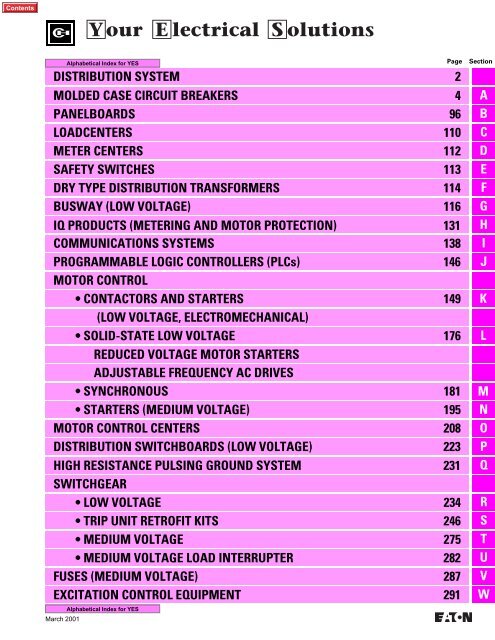
DISTRIBUTION SYSTEM 2<br />
MOLDED CASE CIRCUIT BREAKERS 4<br />
PANELBOARDS 96<br />
LOADCENTERS 110<br />
METER CENTERS 112<br />
SAFETY SWITCHES 113<br />
DRY TYPE DISTRIBUTION TRANSFORMERS 114<br />
BUSWAY (LOW VOLTAGE) 116<br />
IQ PRODUCTS (METERING AND MOTOR PROTECTION) 131<br />
COMMUNICATIONS SYSTEMS 138<br />
PROGRAMMABLE LOGIC CONTROLLERS (PLCs)<br />
MOTOR CONTROL<br />
146<br />
• CONTACTORS AND STARTERS<br />
(LOW VOLTAGE, ELECTROMECHANICAL)<br />
149<br />
• SOLID-STATE LOW VOLTAGE 176<br />
REDUCED VOLTAGE MOTOR STARTERS<br />
ADJUSTABLE FREQUENCY AC DRIVES<br />
• SYNCHRONOUS 181<br />
• STARTERS (MEDIUM VOLTAGE) 195<br />
MOTOR CONTROL CENTERS 208<br />
DISTRIBUTION SWITCHBOARDS (LOW VOLTAGE) 223<br />
HIGH RESISTANCE PULSING GROUND SYSTEM<br />
SWITCHGEAR<br />
231<br />
• LOW VOLTAGE 234<br />
• TRIP UNIT RETROFIT KITS 246<br />
• MEDIUM VOLTAGE 275<br />
• MEDIUM VOLTAGE LOAD INTERRUPTER 282<br />
FUSES (MEDIUM VOLTAGE) 287<br />
EXCITATION CONTROL EQUIPMENT 291<br />
March 2001<br />
Page<br />
Section<br />
A<br />
B<br />
C<br />
D<br />
E<br />
F<br />
G<br />
H<br />
I<br />
J<br />
K<br />
L<br />
M<br />
N<br />
O<br />
P<br />
Q<br />
R<br />
S<br />
T<br />
U<br />
V<br />
W
2<br />
DISTRIBUTION SYSTEM<br />
A Commitment to the Installed Base<br />
Our employees are committed to supporting<br />
all Cutler-Hammer and Westinghouse equipment,<br />
no matter when it was manufactured<br />
or how long it has been in service. Our<br />
dedicated Aftermarket Organization provides<br />
products, services and expertise through a<br />
focused management team, sales engineers<br />
and technicians that work to keep customers’<br />
equipment operating.<br />
Replacement Components<br />
and Renewal Parts<br />
A full line of replacement components and<br />
renewal parts is available for the existing<br />
installed base of Cutler-Hammer and Westinghouse<br />
equipment. These replacement<br />
components and renewal parts are new, not<br />
used or surplus material. The use of original<br />
production tooling, assembly fixtures, and<br />
original specifications and drawings guarantees<br />
compatibility with existing equipment.<br />
Standardize and Expand<br />
Circuit Protection<br />
Digitrip RMS Trip Unit<br />
Retrofit Kits are available<br />
for Cutler-Hammer,<br />
Westinghouse, and other<br />
manufacturers of low voltage<br />
power <strong>breakers</strong>. These<br />
retrofits will expand <strong>circuit</strong><br />
protection while increasing<br />
breaker and electrical<br />
system reliability.<br />
Motor Control Center<br />
Bucket Retrofits<br />
Freedom 2100 and<br />
ADVANTAGE replacement<br />
starter units can be used to<br />
increase the capacity of a<br />
motor control center without<br />
investing in a completely<br />
new assembly. Competitive<br />
retrofits are also available<br />
for other manufacturers’<br />
units using the<br />
ADVANTAGE MCC Bucket<br />
Retrofits.<br />
Replacement<br />
Vacuum Breakers<br />
DHP-VR vacuum replacement<br />
<strong>breakers</strong> provide a<br />
means to cost effectively<br />
modernize existing air<br />
magnetic medium voltage<br />
switchgear while further<br />
increasing its effective life.<br />
Switchgear Fluidized<br />
Epoxy Bus<br />
Existing switchgear<br />
bus can be replaced or<br />
returned to our factory,<br />
regardless of the original<br />
manufacturer for<br />
reinsulation, using the<br />
custom fluidized epoxy<br />
bed process. It is available<br />
from 600 volts to 15 kV<br />
for switchgear, bus runs,<br />
and other equipment.<br />
Equipment Modernization and Upgrades<br />
Cutler-Hammer can extend the life of your<br />
existing equipment through modernization<br />
that can economically upgrade Cutler-<br />
Hammer and Westinghouse products, as<br />
well as those of other manufacturers. These<br />
state-of-the-art upgrades are engineered to<br />
provide:<br />
■ Solutions for obsolete electrical equipment;<br />
■ New technology for aging equipment;<br />
■ Retrofit, repair and remanufacturing processes;<br />
■ Monitoring, protection and control capabilities<br />
to your system;<br />
■ Genuine new replacement components and<br />
renewal parts.<br />
Medium Voltage<br />
Starter Upgrading<br />
Vacuum contactors can<br />
be retrofitted or retrofilled<br />
into existing medium<br />
voltage air magnetic<br />
starters, achieving the<br />
benefits of vacuum<br />
technology without the<br />
expense of a completely<br />
new assembly.<br />
Power Breaker<br />
Replacement<br />
New DS or SPB power<br />
<strong>breakers</strong> are available for<br />
replacement, to fill existing<br />
cells, or in a cell retrofit<br />
package for upgrading<br />
existing older low voltage<br />
switchgear. These <strong>breakers</strong><br />
are electrically and<br />
mechanically identical to<br />
the original vintages of<br />
DS and SPB <strong>breakers</strong>.<br />
Low Voltage High<br />
Resistance Pulsing<br />
Ground Systems<br />
Type C-HRG provides<br />
service continuity by<br />
providing a ground path<br />
for ground current via<br />
resistance that limits<br />
current magnitude and<br />
includes a means to<br />
trace the fault source.<br />
Submetering<br />
Retrofitting<br />
The IQ Energy Sentinel<br />
submetering device can<br />
be easily retrofitted on<br />
Series C Breakers, or<br />
those of other manufacturers,<br />
in existing equipment.<br />
When combined with the<br />
PowerNet System, the IQ<br />
Energy Sentinel can now<br />
provide submetering at<br />
numerous levels of<br />
monitoring and energy<br />
management.<br />
Products and Services for Life Extension<br />
and Equipment Upgrades<br />
Tab<br />
1 Digitrip RMS Trip Unit Retrofit Kits ........................ S<br />
2 Motor Control Center Bucket Retrofits.................... O<br />
3 DHP-VR Vacuum Replacement Breaker ................ T<br />
4 Switchgear Fluidized Epoxy Bus ............................. G<br />
5 Retrofit/Replace with Vacuum Contactors .......... R, T<br />
6 Cell Retrofit with DSII/SPB Circuit Breakers ........... R<br />
7 Low Voltage High Resistance<br />
Pulsing Ground Systems ....................................... Q<br />
8 IMPACC Communication System ............................ I<br />
9 Retrofit Front Panel with IQ Devices ....................... H<br />
10 Retrofit with IQ Energy Sentinel for Submetering ..................................................... H<br />
11 Retrofit with Transient Voltage<br />
Surge Suppression System .................. B, G, O, P, R<br />
12 Replacement Molded Case Breakers<br />
and Parts ................................................................ A<br />
13 Rebuilding/Remanufacturing Service ... A, J, L, N, P, R, T<br />
14 Renewal/Replacement Parts ............................... ALL<br />
Retrofit TVSS System<br />
Protect solid state devices from<br />
the damaging effects of transient<br />
overvoltages. Retrofit<br />
TVSS systems can be installed<br />
in low voltage distribution gear<br />
or retrofitted into existing<br />
switchboards, panelboards,<br />
and motor control center units<br />
to eliminate the transient<br />
surge before it can reach<br />
sensitive equipment.<br />
Replacement Molded Case<br />
Breakers and Parts<br />
Panelboard and motor control<br />
center replacement<br />
<strong>breakers</strong> and parts are physically<br />
interchangeable with outof-production<br />
<strong>breakers</strong> for<br />
existing Cutler-Hammer and<br />
Westinghouse products.<br />
Excitation Control<br />
Cutler-Hammer offers a<br />
complete family of static<br />
exciters designed for<br />
application on medium<br />
to large electric utility<br />
and industrial generators<br />
and motors.<br />
Installation and<br />
Start-Up Services<br />
Installation and start-up<br />
services can be provided<br />
for Cutler-Hammer<br />
equipment, as well as<br />
equipment manufactured<br />
by other organizations.<br />
March 2001
MARGIN<br />
March 2001<br />
SECONDARY<br />
SPOT NETWORK<br />
WITH NETWORK<br />
PROTECTORS<br />
1<br />
6<br />
7<br />
8<br />
9<br />
ADDITIONAL<br />
UTILITY<br />
SOURCES<br />
14<br />
10<br />
11<br />
12<br />
14<br />
DRY-TYPE<br />
DISTRIBUTION<br />
TRANSFORMER<br />
8<br />
LIGHTING<br />
CONTROL<br />
PANELBOARD<br />
OFFICE BUILDING<br />
LOW VOLTAGE BUS 14<br />
8<br />
9<br />
10<br />
11<br />
12<br />
14<br />
8<br />
12<br />
13<br />
14<br />
8<br />
9<br />
14<br />
LOAD<br />
INTERRUPTER<br />
SWITCHGEAR<br />
9 14 14 8<br />
SAFETY<br />
SWITCH<br />
UTILITY SYSTEM<br />
LOW VOLTAGE<br />
SWITCHBOARD<br />
INDIVIDUAL/<br />
GROUP<br />
MOUNTED<br />
UP TO 300 HP<br />
ENCLOSED<br />
CONTROL<br />
14<br />
SAFETY<br />
SWITCH<br />
MEDIUM VOLTAGE<br />
NON-SEGREGATED BUS<br />
TRANSFORMER<br />
SAFETY<br />
SWITCH<br />
LOW VOLTAGE<br />
DISTRIBUTION<br />
PANELBOARD<br />
14<br />
14<br />
8<br />
4<br />
8<br />
9<br />
14<br />
LIGHTING<br />
CONTROL<br />
PANELBOARD<br />
GENERATOR<br />
14<br />
8<br />
9<br />
10<br />
11<br />
12<br />
14<br />
8<br />
14<br />
MOTOR<br />
CONTROL<br />
CENTER<br />
LIGHTING<br />
PANELBOARD<br />
MANUFACTURING FACILITY<br />
DISTRIBUTION SYSTEM<br />
ARC RESISTANT<br />
SWITCHGEAR<br />
1 4 5 6 7 8 9<br />
13 14<br />
8<br />
2<br />
11<br />
8<br />
12<br />
12 14<br />
LOW VOLTAGE<br />
SECONDARY UNIT<br />
SUBSTATION<br />
RECTIFIER<br />
AND<br />
EXCITER<br />
9<br />
14<br />
10<br />
LOW VOLTAGE<br />
DISTRIBUTION<br />
PANELBOARD<br />
LIGHTING<br />
PANELBOARD<br />
34.5 kV<br />
SWITCHGEAR<br />
POWER<br />
TRANSFORMER<br />
15 kV<br />
SWITCHGEAR<br />
SYNCHRONOUS<br />
MOTOR FIELD<br />
APPLICATION<br />
PANEL<br />
LOW<br />
VOLTAGE<br />
TRANSFER<br />
SWITCH<br />
8 10 11 12 14<br />
14 14<br />
LIGHTING<br />
PANELBOARD<br />
GROUNDING<br />
RESISTOR<br />
IMPACC<br />
INTEGRATED<br />
MONITORING<br />
PROTECTION<br />
AND CONTROL<br />
COMMUNICATION<br />
SYSTEM<br />
5<br />
8<br />
13<br />
14<br />
8<br />
11<br />
14<br />
UP TO 700 HP<br />
COUNT<br />
CONTROL<br />
MEDIUM VOLTAGE<br />
TRANSFER EQUIPMENT<br />
VACUUM BREAKERS<br />
OR LOAD BREAK<br />
FUSED SWITCHES<br />
SYNCHRONOUS<br />
MOTOR<br />
8<br />
14<br />
14<br />
LOAD<br />
INTERRUPTER<br />
SWITCHGEAR<br />
ADJUSTABLE<br />
FREQUENCY<br />
CONTROL<br />
PROGRAMMABLE<br />
LOGIC<br />
CONTROLLER<br />
14<br />
PROXIMITY<br />
SENSOR<br />
9 14<br />
MEDIUM<br />
VOLTAGE<br />
STARTER<br />
ON-SITE<br />
GENERATION<br />
UP TO 1500 HP<br />
LIMIT<br />
SWITCH<br />
TRANSFORMER<br />
13<br />
14<br />
EXCITATION<br />
CONTROL<br />
14<br />
DC<br />
DRIVE<br />
MAGNETIC SHOEBREAK<br />
8 10 12 14<br />
8<br />
11<br />
14<br />
14<br />
BUS PLUG<br />
REDUCED<br />
VOLTAGE<br />
STARTER<br />
8<br />
14<br />
14<br />
3 4 5 8 9<br />
13 14<br />
MEDIUM VOLTAGE<br />
SWITCHGEAR<br />
8<br />
9<br />
14<br />
UP TO 300 HP<br />
START STOP<br />
SELECTOR<br />
SWITCH<br />
8<br />
14<br />
HIGH CURRENT<br />
LOW VOLTAGE<br />
PROCESS<br />
14<br />
14<br />
PROCESS<br />
RECTIFIER<br />
SYSTEM<br />
BUS PLUG<br />
ENCLOSED<br />
CONTROL<br />
14<br />
SAFETY<br />
SWITCH<br />
ELECTRICAL<br />
OPERATOR<br />
INTERFACE<br />
PHOTOELECTRIC<br />
SENSOR<br />
14<br />
3
4<br />
MOLDED CASE CIRCUIT BREAKERS<br />
TABLE OF CONTENTS<br />
Pages<br />
Product Description, History, Major Product Introduction . . . . . . . . . . . . . . . . . . . . . . . . . . . . . . . . . . . . . . . . . . . . . . . . . . . . . . 5<br />
General Information . . . . . . . . . . . . . . . . . . . . . . . . . . . . . . . . . . . . . . . . . . . . . . . . . . . . . . . . . . . . . . . . . . . . . . . . . . . . . . . . . . .6-8<br />
● Nameplate Data<br />
● Identifying Factory Original Circuit Breakers<br />
● Replacement and Upgrade Options<br />
Digitrip OPTIM System . . . . . . . . . . . . . . . . . . . . . . . . . . . . . . . . . . . . . . . . . . . . . . . . . . . . . . . . . . . . . . . . . . . . . . . . . . . . . . . .9-12<br />
Miniature Circuit Breakers. . . . . . . . . . . . . . . . . . . . . . . . . . . . . . . . . . . . . . . . . . . . . . . . . . . . . . . . . . . . . . . . . . . . . . . . . . . . .13-15<br />
Molded Case Circuit Breaker Replacement Guide . . . . . . . . . . . . . . . . . . . . . . . . . . . . . . . . . . . . . . . . . . . . . . . . . . . . . . . . .16-21<br />
Replacement Circuit Breakers. . . . . . . . . . . . . . . . . . . . . . . . . . . . . . . . . . . . . . . . . . . . . . . . . . . . . . . . . . . . . . . . . . . . . . . . . .22-53<br />
Replacement Molded Case Switches . . . . . . . . . . . . . . . . . . . . . . . . . . . . . . . . . . . . . . . . . . . . . . . . . . . . . . . . . . . . . . . . . . . .54-55<br />
Replacement Motor Circuit Protectors. . . . . . . . . . . . . . . . . . . . . . . . . . . . . . . . . . . . . . . . . . . . . . . . . . . . . . . . . . . . . . . . . . . . . 56<br />
Molded Case Circuit Breaker Accessories . . . . . . . . . . . . . . . . . . . . . . . . . . . . . . . . . . . . . . . . . . . . . . . . . . . . . . . . . . . . . . . .58-68<br />
Panelboard Replacement Breakers . . . . . . . . . . . . . . . . . . . . . . . . . . . . . . . . . . . . . . . . . . . . . . . . . . . . . . . . . . . . . . . . . . . . .69-75<br />
Panelboard Replacement Breaker Guide . . . . . . . . . . . . . . . . . . . . . . . . . . . . . . . . . . . . . . . . . . . . . . . . . . . . . . . . . . . . . . . . .70-71<br />
Motor Control Center Replacement Breakers . . . . . . . . . . . . . . . . . . . . . . . . . . . . . . . . . . . . . . . . . . . . . . . . . . . . . . . . . . . . .76-81<br />
Molded Case Circuit Breaker Handle Mechanisms . . . . . . . . . . . . . . . . . . . . . . . . . . . . . . . . . . . . . . . . . . . . . . . . . . . . . . . . .82-94<br />
Further Information . . . . . . . . . . . . . . . . . . . . . . . . . . . . . . . . . . . . . . . . . . . . . . . . . . . . . . . . . . . . . . . . . . . . . . . . . . . . . . . . . . . . 95<br />
Pricing Information . . . . . . . . . . . . . . . . . . . . . . . . . . . . . . . . . . . . . . . . . . . . . . . . . . . . . . . . . . . . . . . . . . . . . . . . . . . . . . . . . . . . 95<br />
March 2001
PRODUCT DESCRIPTION<br />
Molded <strong>case</strong> <strong>circuit</strong> <strong>breakers</strong> are designed<br />
to provide <strong>circuit</strong> protection for low-voltage<br />
distribution systems. They are<br />
described by NEMA as,“. . . a device for<br />
closing and interrupting a <strong>circuit</strong><br />
between separable contacts under both<br />
normal and abnormal conditions,” and<br />
furthermore as,“. . . a breaker assembled<br />
as an integral unit in supporting an<br />
PRODUCT HISTORY<br />
Originally a Westinghouse Product<br />
The need for <strong>molded</strong> <strong>case</strong> <strong>circuit</strong> <strong>breakers</strong><br />
came about in 1918 when numerous<br />
applications for electrical motors resulted in<br />
a demand for a device that would ensure<br />
safe operation and, at the same time, protect<br />
electrical <strong>circuit</strong>s.<br />
During this period, individual motors were<br />
used for the first time in industrial plants to<br />
operate machine tools and in private homes<br />
to operate appliances. Plant electricians<br />
were constantly changing fuses blown during<br />
motor start-ups because of the lack of<br />
properly designed fuses for motor <strong>circuit</strong><br />
protection. Homes experienced similar<br />
problems when electrical <strong>circuit</strong>s were overloaded.<br />
Inspectors were concerned about<br />
fire hazards because of plug fuses being<br />
bridged with pennies and the installation of<br />
fuses with too high of an ampere rating.<br />
Inspection authorities became involved<br />
and attempted to find a solution to the<br />
problem. Meetings with switch manufacturers<br />
were initiated in an effort to find a<br />
MAJOR PRODUCT INTRODUCTION<br />
1923<br />
1927<br />
1939<br />
March 2001<br />
First compact, workable <strong>circuit</strong> breaker developed by Westinghouse<br />
enclosed housing of insulating material.”<br />
The NEC describes them as, “. . . a device<br />
designed to open and close a <strong>circuit</strong> by<br />
non-automatic means, and to open the<br />
<strong>circuit</strong> automatically on a predetermined<br />
overload of current, without injury to itself<br />
when properly applied within its rating.”<br />
Circuit <strong>breakers</strong> protect against overloads<br />
in conductors and protects against short<br />
solution. Switch manufacturers were<br />
asked to develop a switching device that<br />
would interrupt a <strong>circuit</strong> under prolonged<br />
overload conditions. The device would<br />
have to be safe, reliable and tamperproof.<br />
It should also be resettable so as to be<br />
reusable after an interruption without<br />
replacing any parts. This search for better<br />
<strong>circuit</strong> protection resulted in many different<br />
but unacceptable approaches to the<br />
problem. These early meetings and subsequent<br />
efforts prepared the groundwork<br />
for the eventual development of the <strong>molded</strong><br />
<strong>case</strong> <strong>circuit</strong> breaker.<br />
After intensive research and development,<br />
Westinghouse produced the<br />
DE-ION arc extinguisher for use in large<br />
oil <strong>circuit</strong> <strong>breakers</strong>. Although too large in<br />
its initial form to be practical for small<br />
<strong>circuit</strong> <strong>breakers</strong>, the arc extinguisher was<br />
eventually modified into a usable size. The<br />
first compact, workable <strong>circuit</strong><br />
breaker was developed in 1923 when the<br />
Westinghouse introduced the first complete <strong>circuit</strong> breaker line, rated 10-600<br />
amps, 600 volts<br />
Along with ordering information and style numbers, the various maximum current ratings<br />
came to be known by frame designations:<br />
50 Ampere E Frame<br />
100 Ampere F Frame (Non-interchangeable Trip)<br />
100 Ampere G Frame<br />
225 Ampere K Frame<br />
600 Ampere L Frame<br />
1970 Motor Circuit Protector (”MCP“) introduced – First sensitive, low level protection designed specifically for<br />
motor <strong>circuit</strong>s<br />
1973 ”SELTRONIC“ introduced – First <strong>molded</strong> <strong>case</strong> <strong>circuit</strong> breaker with an electronic trip unit<br />
1979 ”Current Limit-R Circuit Breaker“ introduced – First true current limiting <strong>circuit</strong> breaker<br />
1995 ”OPTIM“ Family introduced – First truly programmable <strong>molded</strong> <strong>case</strong> <strong>circuit</strong> breaker<br />
5<br />
<strong>circuit</strong>s in connected apparatus, such as<br />
motors and motor starters.<br />
Circuit <strong>breakers</strong> are designed for use in<br />
panelboards, switchboards, motor control<br />
centers, control panels, combination starters,<br />
individual enclosures, and bus duct<br />
plug-in units.<br />
modified arc extinguisher was coupled<br />
with a thermal tripping mechanism. It was<br />
not until four years later, however, that<br />
Westinghouse research engineers found<br />
the ideal combination of materials and<br />
design that permitted <strong>circuit</strong> <strong>breakers</strong> to<br />
interrupt fault currents of 5000 amperes<br />
at 120 volts AC or DC. One year later,<br />
Westinghouse placed the first <strong>circuit</strong><br />
breaker on the market. Its acceptance was<br />
instantaneous.<br />
Since that initial introduction in 1927,<br />
Westinghouse continued to be at the forefront<br />
of <strong>circuit</strong> breaker technology with an<br />
unprecedented series of <strong>circuit</strong> protective<br />
enhancements and introductions as<br />
chronicled below. In 1994 the <strong>Eaton</strong> Corporation,<br />
another World Class technology<br />
leader, acquired the Westinghouse Distribution<br />
and Control Business Unit and integrated<br />
it with Cutler-Hammer forming a<br />
powerful, new combination, poised to<br />
meet the challenges of the next 100 years.<br />
1920 1930 1940 1950 1960 1970 1980 1990 Present<br />
1982 ”Series C“ Family introduced – New World Class standard meeting increasing interrupting requirements without sacrificing<br />
compact size<br />
1994<br />
MOLDED CASE CIRCUIT BREAKERS<br />
Westinghouse Distribution and Control Business Unit (DCBU) acquired by <strong>Eaton</strong>, integrated with Cutler-Hammer<br />
(The Cutler-Hammer line of <strong>molded</strong> <strong>case</strong> <strong>circuit</strong> <strong>breakers</strong> was sold when merged with Westinghouse)<br />
A
6<br />
Accessories<br />
MOLDED CASE CIRCUIT BREAKERS<br />
General Information<br />
BREAKER IDENTIFICATION<br />
Nameplate Data<br />
A <strong>circuit</strong> breaker is identified by data<br />
found on the nameplate.<br />
This includes:<br />
Catalog Number<br />
Shop Order Number<br />
Style Number<br />
Amperage<br />
Number of Poles<br />
Voltage Class<br />
Temperature Rating<br />
In most instances, the Catalog Number,<br />
Style Number, or Shop Order Number will<br />
supply enough information to identify the<br />
<strong>circuit</strong> breaker. However, it is always advisable<br />
to obtain all data from the nameplate<br />
to facilitate identification.<br />
A Catalog Number begins with a series of<br />
letters followed by numbers that identify:<br />
Circuit Breaker Type<br />
Number of Poles<br />
Maximum Amperage<br />
Example: Catalog Number F3020<br />
indicates a Type F Circuit<br />
Breaker, 3 Poles,<br />
20 Amperes<br />
A Shop Order Number begins with one or<br />
two numbers followed by a single letter<br />
and four additional numbers.<br />
A Shop Order Number is listed in place of<br />
a Catalog Number and indicates the <strong>circuit</strong><br />
breaker was modified at the factory, i.e.,<br />
addition of a shunt trip, special calibration,<br />
etc. Every Shop Order Number must be researched<br />
with the factory to properly<br />
identify modifications. Call your<br />
Cutler-Hammer Field Sales Office for this<br />
information.<br />
Example: 70E2121<br />
NOTE: Cutler-Hammer does not recommend<br />
replacing a <strong>circuit</strong> breaker<br />
identified by a Shop Order Number<br />
with a standard ”off-the-shelf“<br />
<strong>circuit</strong> breaker without first identifying<br />
the modifications. They may<br />
be critical to safe and reliable<br />
operation.<br />
Most <strong>circuit</strong> breaker accessories are<br />
mounted internally and are not visible<br />
with a quick inspection. However, since<br />
many accessories rely on or supply an<br />
external signal, there may be electrical<br />
leads exiting the <strong>circuit</strong> breaker <strong>case</strong>.<br />
Inspect for these leads when obtaining full<br />
descriptive information for <strong>circuit</strong> breaker<br />
replacement. Examples of common<br />
accessories:<br />
➊ Labels updated in 1997.<br />
Shunt Trip<br />
Pre-Series C Breaker with Original Label➊<br />
Series C Breaker with Original Label➊<br />
New Label for Typical SELTRONIC MCCB<br />
Used to remotely trip the <strong>circuit</strong> breaker<br />
using an electrical signal. Typically two<br />
wires extend through the <strong>case</strong>.<br />
Undervoltage Release (UVR)<br />
Trips the <strong>circuit</strong> breaker when voltage<br />
drops below a specified percentage of coil<br />
voltage (typically 70%). Typically two<br />
wires extend through the <strong>case</strong>.<br />
Auxiliary Switch<br />
Provides remote indication of the <strong>circuit</strong><br />
breaker status (open/closed). Typically<br />
three wires extend through <strong>case</strong> in a<br />
1-pole 1A/1B application.<br />
Alarm Lockout Switch<br />
For remote indication of an automatic trip<br />
operation. Typically two or three wires<br />
extend through the <strong>case</strong>.<br />
March 2001
FACTORY ORIGINAL CIRCUIT BREAKERS<br />
Why Insist on Only Genuine, New MCCBs Purchased Through Authorized Distributors?<br />
Cutler-Hammer defines “New” product as<br />
that which has not yet been installed in an<br />
electrical <strong>circuit</strong>, purchased through<br />
authorized channels in factory original<br />
condition and packaged in unopened<br />
Cutler-Hammer cartons.<br />
●<br />
The only way to ensure safe and reliable<br />
operation of your system is to use genuine,<br />
new, Cutler-Hammer products<br />
exclusively. Since Cutler-Hammer does<br />
not resell the component parts for mold-<br />
Identifying Genuine, Factory Original Westinghouse Circuit Breakers Manufactured by Cutler-Hammer<br />
The features on a <strong>molded</strong> <strong>case</strong> <strong>circuit</strong><br />
breaker that identify it as genuine or counterfeit<br />
may or may not be readily apparent.<br />
In fact, there may be differences not<br />
detectable by an external investigation.<br />
1. ➀ A genuine Westinghouse brand<br />
<strong>molded</strong> <strong>case</strong> <strong>circuit</strong> breaker manufactured<br />
by Cutler-Hammer will have an<br />
unbroken seal where the <strong>case</strong> comes<br />
together. This seal was placed at the<br />
factory and assures the internal integrity<br />
of the breaker. If, for any reason<br />
this seal is broken, do not accept the<br />
breaker. (Seal does not appear on<br />
interchangeable trip <strong>breakers</strong>.)<br />
2. ➁ There is a manufacturing date code on<br />
the back of genuine <strong>molded</strong> <strong>case</strong> <strong>circuit</strong><br />
<strong>breakers</strong> stamped in silver and<br />
white. If this coding is missing, it may<br />
mean the breaker has been subjected<br />
to tampering. Frequently, this date<br />
code is wiped off in an attempt to represent<br />
the breaker as new.<br />
3. ➂ Another way to tell if a breaker has<br />
been tampered with is to examine the<br />
sealant used to cover the screws on<br />
the top rear of the breaker. If the sealant<br />
appears sloppy or is missing, it<br />
indicates that the unit may have been<br />
subjected to tampering.<br />
4. ➃ A UL label on a genuine Westinghouse<br />
breaker is either exactly as shown in<br />
the photo or is stamped in white ink<br />
onto the frame in older pre-Series C<br />
<strong>breakers</strong>. Anything other than this may<br />
indicate fraud.<br />
5. ➄ If front cover screw shows marks from<br />
use, someone has attempted to open<br />
the breaker. The front covers are either<br />
black or gray on genuine Westinghouse<br />
<strong>molded</strong> <strong>case</strong> <strong>circuit</strong> <strong>breakers</strong>.<br />
6. ➅ Westinghouse <strong>molded</strong> <strong>case</strong> <strong>circuit</strong><br />
<strong>breakers</strong> manufactured by Cutler-<br />
Hammer are packed individually and<br />
shipped in Cutler-Hammer labeled cartons.<br />
Anything other than this is not to<br />
be considered new and should be<br />
suspect.<br />
March 2001<br />
MOLDED CASE CIRCUIT BREAKERS<br />
General Information<br />
●<br />
ed <strong>case</strong> <strong>circuit</strong> <strong>breakers</strong>, the only way for<br />
third party breaker refurbishers to get<br />
parts for the <strong>breakers</strong> that they are<br />
rebuilding is to cannibalize other used<br />
<strong>breakers</strong> or to use counterfeit components.<br />
Neither is a very good option for<br />
the end user.<br />
In some <strong>case</strong>s, unauthorized resellers<br />
of <strong>molded</strong> <strong>case</strong> <strong>circuit</strong> <strong>breakers</strong> have<br />
been found to misrepresent used,<br />
rebuilt, or surplus products. Only<br />
➀ ➁<br />
➂ ➃<br />
➄ ➅<br />
●<br />
7<br />
products purchased as ”new“ through<br />
authorized channels are covered under<br />
the Cutler-Hammer warranty policy.<br />
There have been instances where third<br />
party refurbishers have rebuilt <strong>breakers</strong><br />
using the wrong parts, with parts missing<br />
or the factory lubrication removed<br />
in the cleaning process — any of which<br />
may result in devices that may not be<br />
depended upon to function properly to<br />
protect equipment and personnel.<br />
A
8<br />
MOLDED CASE CIRCUIT BREAKERS<br />
REPLACEMENT CAPABILITIES<br />
Series C Molded Case Circuit Breakers<br />
When and Where to Use:<br />
● Generally a first choice wherever physically and electrically<br />
practical<br />
● Where communications, energy and power quality monitoring<br />
are desired<br />
● As a direct replacement or add-on to already installed Series C<br />
product<br />
● Where ampere rating flexibility is desired. (Interchangeable trip<br />
units are available.)<br />
Current Production Replacement Circuit Breakers<br />
When and Where to Use:<br />
● As a direct, one-for-one replacement of current production<br />
pre-Series C product<br />
● Where you know the catalog/style number but not the physical or<br />
electrical specifics about the application<br />
Replacement of Out-of-Production Panelboard or Motor Control Center Molded Case Circuit Breakers<br />
When and Where to Use:<br />
● When replacing out-of-production <strong>circuit</strong> <strong>breakers</strong> in an existing<br />
Panelboard or MCC<br />
Factory Reconditioned Molded Case Circuit Breakers<br />
When and Where to Use:<br />
● Where Series C and other replacement breaker options are either<br />
not available or not workable<br />
● Where it is not feasible to modify or upgrade gear but there is a<br />
need to replace or add a <strong>circuit</strong> breaker<br />
Service for Molded Case Circuit Breakers<br />
When and Where to Use:<br />
● Where <strong>circuit</strong> breaker has sustained minor physical damage to a<br />
handle, lug, etc., that otherwise would be fully functional<br />
● Large frame <strong>circuit</strong> breaker (600A and above) that has experienced<br />
some normal wear, but is in generally good condition, as<br />
an economically driven alternative to new<br />
Advantages:<br />
● Most current <strong>molded</strong> <strong>case</strong> <strong>circuit</strong> breaker technology<br />
● Higher interrupting capacities in each frame size<br />
● Smaller and lighter for a given frame size than other options<br />
● Generally less expensive than other replacement breaker options<br />
● Readily available throughout range / High levels of stock<br />
● Available from stock<br />
● One year warranty<br />
Advantages:<br />
● Ease of selection and certainty of replacement<br />
● Guaranteed to be both a physical and electrical duplicate of<br />
original<br />
● Still in production<br />
● Newly manufactured<br />
● UL listed<br />
● Available from stock<br />
● One year warranty<br />
Advantages:<br />
● Newly manufactured and tested to the latest applicable standards<br />
● Both physically and electrically interchangeable with the <strong>circuit</strong><br />
<strong>breakers</strong> that they are designed to replace<br />
● UL listed<br />
● Available from stock in most frame sizes<br />
● One year warranty<br />
Advantages:<br />
● Though not UL listed, these <strong>breakers</strong> are reconditioned and<br />
tested by Cutler-Hammer at the factory according to the original<br />
manufacturing and engineering standards to which the <strong>breakers</strong><br />
were built<br />
● Available for all styles of out-of-production <strong>circuit</strong> <strong>breakers</strong><br />
(E, F, G, J, K, L, M, P)<br />
● Knowledge that these <strong>breakers</strong> are both safe and reliable<br />
● Labeled ”Reconditioned Circuit Breaker, Resold By Cutler-Hammer“<br />
Advantages:<br />
● Prevents loss of <strong>circuit</strong> <strong>breakers</strong> due to minor damage<br />
● Reduces overall breaker costs<br />
● Prevents use of potentially unreliable third party refurbishers<br />
● Includes full one year Cutler-Hammer Warranty<br />
● Ensures reliability through dealing with the original manufacturer<br />
with a long and well-recognized tradition of product safety,<br />
integrity and quality<br />
● Provides a simple and convenient solution<br />
March 2001
NEW TECHNOLOGY<br />
Digitrip OPTIM is a new programmable<br />
communicating microprocessor-based<br />
low-voltage electronic trip unit system for<br />
Westinghouse Series C Molded Case<br />
Circuit Breakers and low-voltage power<br />
<strong>breakers</strong>. Digitrip OPTIM trip units are<br />
available in two styles, Digitrip OPTIM 750<br />
and Digitrip OPTIM 1050, in Series C<br />
frames L-, N-, and R-70 through 2500<br />
amperes.<br />
Digitrip OPTIM trip units are fully programmable<br />
and can be applied as a<br />
stand-alone breaker with a hand-held<br />
Digitrip OPTIMizer programmer for configuring<br />
the trip unit, displaying information<br />
and testing. In addition, OPTIM can<br />
be applied as a low-voltage assembly<br />
with a panel mounted Breaker Interface<br />
Module (BIM) to configure, display and<br />
test. Alternatively, OPTIM can be applied<br />
as part of a fully integrated IMPACC<br />
system.<br />
March 2001<br />
MOLDED CASE CIRCUIT BREAKERS<br />
Digitrip OPTIM System<br />
Stand Alone<br />
The hand-held Digitrip OPTIMizer is used<br />
to program individual OPTIM Trip Units.<br />
Sub-Network<br />
The Breaker Interface Module, mounted<br />
on the assembly or at a remote location, is<br />
used to access, configure, and display<br />
information from Digitrip OPTIM Trip<br />
Units. Any combination of OPTIM Trip<br />
Units and/or Digitrip RMS 810/910 Trip<br />
Units and/or IQ Energy Sentinels<br />
(up to<br />
50 devices) can communicate with the<br />
Breaker Interface Module.<br />
Field Bus<br />
With Integrated Monitoring, Protection<br />
and Control Communications (IMPACC),<br />
the plant operator, facilities engineer, and/<br />
or maintenance engineer can monitor and<br />
control the entire power distribution system<br />
from a central PC.<br />
9<br />
Typical OPTIM Applications<br />
When more information is required to<br />
better manage your production process.<br />
In a critical process such as a batch reactor<br />
used in the food, chemical, pharmaceutical,<br />
and petroleum industries.<br />
Material in the process vessel can be<br />
worth more than the equipment required<br />
to produce it. This application requires<br />
close coordination with the overall electrical<br />
distribution system, possible isolation<br />
from the main switchboard, higher levels<br />
of overload and fault protection, remote<br />
breaker status indications, controlled shutdown<br />
sequence, monitoring, and data collection.<br />
When early warning information that<br />
reduces downtime is required. On a critical<br />
production line such as an automatic feeder<br />
supplying subassemblies for a finished<br />
product used in the automotive industry,<br />
or by OEMs and electric product manufacturers.<br />
Automated welding and paint lines,<br />
for example, require higher levels of overload<br />
and fault protection, advanced warning<br />
of an impending trip condition, and<br />
system diagnostics which reduce the time<br />
necessary to get back on line.<br />
When there is a concern with system<br />
obsolescence. When upgrading your facility’s<br />
electrical distribution system, there<br />
could be a requirement to replace obsolete<br />
main or branch protection devices<br />
where space is limited. Feeders for laboratories<br />
and computer rooms could require<br />
better coordination and protection, while<br />
specialized equipment such as engine<br />
generators and variable frequency drives<br />
could also require upgraded protection.<br />
OPTIM meets these requirements economically<br />
because they provide high<br />
reliability and increased performance in<br />
a compact, dustproof unit that is wall<br />
mountable. Rewiring costs are minimized.<br />
A Digitrip OPTIM Enclosed Circuit Breaker<br />
can be locked in the off position to comply<br />
with OSHA lockout/tagout regulations,<br />
and meet the NEC 430 requirements for<br />
a separate disconnect within sight of<br />
motor loads.<br />
A
10<br />
MOLDED CASE CIRCUIT BREAKERS<br />
Digitrip OPTIM System<br />
NEW TECHNOLOGY, Continued<br />
Programmability Increases Protection<br />
and Coordination Capabilities<br />
Several unique protection and coordination<br />
features can be electronically programmed<br />
to provide:<br />
● Time-current settings with more increments<br />
that permit the user to optimize<br />
system protection and coordination.<br />
● Improved accuracy giving more selectivity<br />
and closer sensitivity in providing<br />
coordination.<br />
● Improved reliability provided by displaying<br />
time-current setpoints in actual<br />
amperes.<br />
● Programmable short delay and/or<br />
instantaneous curve tripping options.<br />
● Selectable powered and unpowered<br />
thermal memory as well as selectable<br />
sure start discriminator protection<br />
features.<br />
● Increased system security provided by<br />
the addition of programmable password<br />
protection.<br />
For improved system coordination, we<br />
have added:<br />
● I4t<br />
long delay time slope to the traditional<br />
nine Long Time, Short Time,<br />
Instantaneous, and Ground Fault<br />
(LSIG) curve shaping options.<br />
●<br />
Short delay and ground delay zone<br />
selective interlocking down to a 70<br />
ampere <strong>molded</strong> <strong>case</strong> <strong>circuit</strong> breaker.<br />
Digitrip OPTIM Trip Units can be programmed<br />
with hand-held OPTIMizer (above) that plugs<br />
into the front of the trip unit; or with the Breaker<br />
Interface Module mounted directly on the<br />
enclosure door.<br />
Advance Warning Alerts to Potential<br />
Problems<br />
This feature helps keep your system operating<br />
and more productive with:<br />
● Programmable high load phase and<br />
neutral alarm, adjustable between 50%<br />
and 100% of Ir<br />
Long Delay Pick Up<br />
(LDPU) setting, that will signal an<br />
impending trip condition.<br />
●<br />
●<br />
●<br />
Adjustable ground fault alarm that will<br />
alert the user of a ground fault condition<br />
without tripping the breaker.<br />
Energy alarming (such as peak demand<br />
exceeded) to reduce energy costs with<br />
OPTIM 1050 via IMPACC.<br />
Total Harmonic Distortion (THD)<br />
alarming detects changes in power<br />
quality with OPTIM 1050 via IMPACC.<br />
System Diagnostics<br />
Provide Reduced Downtime<br />
Digitrip OPTIM provides a complete<br />
selection of system diagnostic capabilities<br />
such as:<br />
● Four cause-of-trip Light Emitting<br />
Diodes (LEDs) mounted on the front of<br />
the trip unit to improve troubleshooting<br />
capabilities along with trip event information<br />
that is stored in memory<br />
after a trip condition.<br />
●<br />
●<br />
Remote breaker status indicator provided<br />
by auxiliary and alarm switches.<br />
The Breaker Interface Module (BIM)<br />
provides trip indication information on<br />
the front of the unit itself or via relay<br />
contacts to a remote location.<br />
System Monitoring – “lf You Can’t<br />
Measure It, You Can’t Manage It”<br />
● Digitrip OPTIM has an extensive menu<br />
of system monitoring capabilities:<br />
– Load monitoring (ABCNG).<br />
– Power factor (OPTIM 1050).<br />
– Power and energy (OPTIM 1050).<br />
– Power quality – current harmonics<br />
(OPTIM 1050) with accuracy based on<br />
full scale sensor rating:<br />
• ± 2% Current.<br />
• ± 4% Power.<br />
• ± 5 Energy.<br />
● OPTIM trip units are IMPACC compatible<br />
and can be included in the unique<br />
Cutler-Hammer IMPACC communications<br />
system, specially designed for<br />
electrical distribution applications.<br />
● All OPTIM programming, configuration,<br />
advanced warning, diagnostics,<br />
monitoring, and control capabilities<br />
can be accessed from a central PC<br />
using IMPACC software. Additional<br />
software packages can provide energy<br />
management as well as waveform<br />
capture.<br />
Field Testing to Verify Performance<br />
Trip or no trip testing can be performed on<br />
OPTIM Trip Units to verify operation. Testing<br />
can be completed by using a Digitrip<br />
OPTIMizer, the Breaker Interface Module<br />
or IMPACC software. An auxiliary power<br />
module can be provided for bench testing.<br />
March 2001
NEW TECHNOLOGY, Continued<br />
Digitrip OPTIMizer<br />
Breaker Interface Module<br />
IMPACC Communications<br />
March 2001<br />
MOLDED CASE CIRCUIT BREAKERS<br />
Digitrip OPTIM System<br />
Hand-Held Programmer<br />
The OPTIMizer plugs into the front of the<br />
trip unit and is powered by a nine-volt<br />
battery. The Digitrip OPTIMizer hand-held<br />
programmer accesses, displays and<br />
configures information from OPTIM Trip<br />
Units.<br />
An operator can use the OPTIMizer to:<br />
● Complete Initial System Setup<br />
– Select breaker addresses<br />
– Select system frequency (50/60 Hz)<br />
– Set system baud rate<br />
– Set system password<br />
Panel Mounted User Interface<br />
The Breaker Interface Module can be<br />
mounted directly on the assembly or at a<br />
remote location and can be used to access,<br />
configure and display information from<br />
OPTIM Trip Units.<br />
An operator can use the Breaker Interface<br />
Module to:<br />
● Setup Initial System<br />
– Select system frequency (50/60 Hz)<br />
– Set system password<br />
● Configure the System<br />
– Change time-current setpoints<br />
– Select protection options<br />
– Select alarm levels<br />
● Display Information<br />
– Breaker information<br />
– Time-current setpoints<br />
– Metered values<br />
– Trip event information<br />
● Test Trip Unit Performance<br />
– Phase and ground<br />
– Trip/no trip<br />
Programming and Other Capabilities from<br />
a Personal Computer<br />
All OPTIM programming, configuration,<br />
advance warning, diagnostic, monitoring<br />
and control capabilities can be accessed<br />
from a central personal computer using<br />
IMPACC Series III software. Application<br />
software packages are available to configure<br />
and download setpoints to provide<br />
faster, more efficient system management.<br />
These include:<br />
● Coordination software to display, configure<br />
and coordinate time-current protection<br />
curves for OPTIM Trip Units and<br />
other devices that can be included on<br />
an IMPACC System<br />
● Custom billing software, a stand-alone<br />
application-specific software package,<br />
that provides the capability to determine<br />
energy usage data by individual<br />
departments or tenants in a facility and<br />
● Configure the System<br />
– Change time-current setpoints<br />
– Select protection options<br />
– Select alarm levels<br />
● Display Information<br />
– Breaker information<br />
– Time-current setpoints<br />
– Metered values<br />
– Trip event information<br />
● Test Trip Unit Performance<br />
– Phase and ground<br />
– Trip/no trip<br />
11<br />
All Features of the OPTIMizer PLUS...<br />
● Expanded Energy Monitoring<br />
– Set addresses for group energy<br />
monitoring<br />
– Group energy readings<br />
● Local and Remote Indication<br />
– Remote indication/alarming<br />
– Breaker status LED indication<br />
● Expanded Communications<br />
– Communicates with:<br />
• OPTIM Trip Units<br />
• Digitrip RMS 810 and 910 Trip Units<br />
• IQ Energy Sentinels and Universal<br />
IQ Energy Sentinels<br />
• Up to 50 devices<br />
then create electric bills based on this<br />
data.<br />
● Waveform and harmonic display software<br />
capable of performing a waveform<br />
capture of phase currents A, B and<br />
C. In addition, Total Harmonic Distortion<br />
(THD) and individual harmonic<br />
contents of phase currents A, B, C,<br />
neutral, or ground can be displayed.<br />
A
12<br />
MOLDED CASE CIRCUIT BREAKERS<br />
Digitrip OPTIM Enclosed Circuit Breakers<br />
THIS PAGE INTENTIONALLY LEFT BLANK<br />
March 2001
Quicklag Plug-in Industrial Circuit Breakers<br />
Maximum Amperes 150A 125A 100A 30A<br />
C<br />
U<br />
RRE<br />
N<br />
T<br />
DESIGN<br />
These <strong>circuit</strong> <strong>breakers</strong><br />
replace the out-ofproduction<br />
<strong>circuit</strong><br />
<strong>breakers</strong> listed below.<br />
HQP QPHW QHPX QHPW<br />
Quicklag Bolt-on Industrial Circuit Breakers<br />
C<br />
U<br />
R<br />
R E<br />
N T DESIGN<br />
C<br />
U<br />
R<br />
R E<br />
N T<br />
Dimensions – Inches Per Single Pole Breaker<br />
W H D<br />
1 215 ⁄16 23 ⁄8<br />
Out-of-Production Westinghouse Circuit Breakers<br />
These Circuit Breakers Are<br />
No Longer Manufactured<br />
Recommended QUICKLAG <br />
Circuit Breakers listed above.<br />
Maximum Amperes 150A 100A 125A 100A 30A<br />
These <strong>circuit</strong> <strong>breakers</strong><br />
replace the out-ofproduction<br />
<strong>circuit</strong><br />
<strong>breakers</strong> listed below.<br />
March 2001<br />
BAB GB, GHB QBHW HBAX HBAW<br />
W H D<br />
1 4 2 13 ⁄16<br />
BA<br />
(277V)<br />
Single Pole Only<br />
W H D<br />
1 2 15 ⁄16 2 3 ⁄8<br />
QBH<br />
W H D<br />
1 2 15 ⁄16 2 3 ⁄8<br />
No<br />
Previous<br />
Circuit Breaker<br />
Existed<br />
13<br />
W H D<br />
1 2 15 ⁄16 2 3 ⁄8<br />
Maximum Amperes 60 60 100A 100A 100A 30A<br />
These <strong>circuit</strong> <strong>breakers</strong><br />
replace the out-ofproduction<br />
<strong>circuit</strong><br />
<strong>breakers</strong> listed below.<br />
HQNPL, HQNPAL,<br />
HQNP, HQNPA, QP,<br />
QPA, QPAH, QNPL,<br />
QNPAL, QNP<br />
Type P, PL<br />
Dimensions – Inches Per Single Pole Breaker<br />
W H D<br />
1 215 ⁄16 23 ⁄8<br />
Out-of-Production Westinghouse Circuit Breakers<br />
These Circuit Breakers Are<br />
No Longer Manufactured<br />
Recommended QUICKLAG <br />
HQNB<br />
HQNBA<br />
QB, BA<br />
QNBL<br />
Circuit Breakers listed above. QNBAL<br />
Quicklag Cable-in/Cable-out Industrial Circuit Breakers<br />
D<br />
E<br />
S<br />
I<br />
G Dimensions – Inches Per Single Pole Breaker<br />
N<br />
W H D<br />
1<br />
⁄2 315 ⁄16 27 ⁄16<br />
Out-of-Production Westinghouse Circuit Breakers<br />
These Circuit Breakers Are<br />
No Longer Manufactured<br />
Recommended QUICKLAG <br />
No<br />
Previous<br />
Circuit Breakers listed above.<br />
Circuit Breaker<br />
Existed<br />
MOLDED CASE CIRCUIT BREAKERS<br />
Miniature Circuit Breakers<br />
MINIATURE CIRCUIT BREAKER REPLACEMENT GUIDE<br />
QCR QCF QC QCHW QHCX QHCW<br />
W H D<br />
1 ⁄2 3 15 ⁄16 2 7 ⁄16<br />
No<br />
Previous<br />
Circuit Breaker<br />
Existed<br />
W H D<br />
1 2 15 ⁄16 2 3 ⁄8<br />
QPH<br />
W H D<br />
1 3 3 ⁄4 2 7 ⁄16<br />
HQCL<br />
HQCAL<br />
HQC, HQCA<br />
QCA<br />
W H D<br />
1 2 15 ⁄16 2 3 ⁄8<br />
No<br />
Previous<br />
Circuit Breaker<br />
Existed<br />
W H D<br />
1 3 3 ⁄4 2 7 ⁄16<br />
QCH<br />
W H D<br />
1 3 3 ⁄4 2 7 ⁄16<br />
No<br />
Previous<br />
Circuit Breaker<br />
Existed<br />
W H D<br />
1 2 15 ⁄16 2 3 ⁄8<br />
QHPL<br />
QHP<br />
HBA<br />
W H D<br />
1 3 3 ⁄4 2 7 ⁄16<br />
QHCL<br />
QHC<br />
A
14<br />
Circuit Breaker Selection Guide<br />
Circuit<br />
Breaker<br />
Type<br />
HQP<br />
HQP<br />
HQP<br />
QPHW<br />
QPHW<br />
QPHW<br />
QHPX<br />
QHPX<br />
QHPX<br />
QHPW<br />
QHPW<br />
QHPW<br />
QPGF<br />
QPGF<br />
QPHGF<br />
QPHGF<br />
QPGFEP<br />
QPGFEP<br />
QPHGFEP<br />
QPHGFEP<br />
BAB<br />
BAB<br />
BAB<br />
QBHW<br />
QBHW<br />
QBHW<br />
HBAX<br />
HBAX<br />
HBAX<br />
HBAW<br />
HBAW<br />
HBAW<br />
QBGF<br />
QBGF<br />
QBHGF<br />
QBHGF<br />
QBGFEP<br />
QBGFEP<br />
QBHGFEP<br />
QBHGFEP<br />
QC<br />
QC<br />
QC<br />
QC<br />
QCF<br />
QCR<br />
QCHW<br />
QCHW<br />
QCHW<br />
QHCX<br />
QHCX<br />
QHCX<br />
QHCW<br />
QHCW<br />
QHCW<br />
QCGF<br />
QCGF<br />
QCHGF<br />
QCHGF<br />
QCGFEP<br />
QCGFEP<br />
QCHGFEP<br />
QCHGFEP<br />
MOLDED CASE CIRCUIT BREAKERS<br />
Miniature Circuit Breakers<br />
QUICKLAG MINIATURE CIRCUIT BREAKERS<br />
QUICKLAG is the largest and most complete<br />
family of industrial thermal magnetic<br />
miniature <strong>circuit</strong> <strong>breakers</strong>. They provide<br />
the exclusive features of steel frame calibration<br />
and arc chutes in every pole.<br />
QUICKLAG <strong>circuit</strong> <strong>breakers</strong> are provided in<br />
ranges from 5 to 125 amperes continuous<br />
Circuit<br />
Breaker<br />
Type<br />
Code<br />
Cont.<br />
Ampere<br />
Rating<br />
At 40°C<br />
P 5-70<br />
10-125<br />
10-100<br />
P 15-70<br />
15-125<br />
15-100<br />
P 15-70<br />
15-100<br />
15-100<br />
P 15-30<br />
15-30<br />
15-30<br />
P, GF 15-30<br />
15-50<br />
P, GF 15-30<br />
15-50<br />
P, GFEP 15-30<br />
15-50<br />
P, GFEP 15-30<br />
15-30<br />
B 5-70<br />
10-125<br />
10-100<br />
B 15-70<br />
15-125<br />
15-100<br />
B 15-70<br />
15-100<br />
15-100<br />
B 15-30<br />
15-30<br />
15-30<br />
B, GF 15-30<br />
15-50<br />
B, GF 15-30<br />
15-30<br />
B, GFEP 15- 30<br />
15- 50<br />
B, GFEP 15- 30<br />
15- 30<br />
C 5- 70<br />
10-100<br />
10-100<br />
15-100<br />
C 10-60<br />
10-60<br />
C 15-70<br />
15-100<br />
15-100<br />
C 15- 70<br />
15-100<br />
15-100<br />
C 15-30<br />
15-30<br />
15-30<br />
C. GF 15- 30<br />
15- 50<br />
C. GF 15- 30<br />
15- 30<br />
C, GFEP 15- 30<br />
15- 30<br />
C, GFEP 15- 30<br />
15- 30<br />
No.<br />
Poles<br />
1<br />
2<br />
2, 3<br />
1<br />
2<br />
2, 3<br />
1<br />
2<br />
3<br />
1<br />
2<br />
3<br />
1<br />
2<br />
1<br />
2<br />
1<br />
2<br />
1<br />
2<br />
1<br />
2<br />
2, 3<br />
1<br />
2<br />
2, 3<br />
1<br />
2<br />
3<br />
1<br />
2<br />
3<br />
1<br />
2<br />
1<br />
2<br />
1<br />
2<br />
1<br />
2<br />
1<br />
2<br />
2, 3<br />
4<br />
1, 2<br />
1, 2<br />
1<br />
2<br />
2, 3<br />
1<br />
2<br />
3<br />
1<br />
2<br />
3<br />
1<br />
2<br />
1<br />
2<br />
1<br />
2<br />
1<br />
2<br />
Volts Federal<br />
UL Listed Interrupting Ratings RMS Symmetrical Amperes<br />
AC DC<br />
Spec.<br />
W-C-375b<br />
AC Ratings Volts DC❶<br />
120 120/240 240 24 48 80<br />
120/240<br />
120/240<br />
240<br />
120/240<br />
120/240<br />
240<br />
120/240<br />
120/240<br />
240<br />
120/240<br />
120/240<br />
240<br />
120<br />
120/240<br />
120<br />
120/240<br />
120<br />
120/240<br />
120<br />
120/240<br />
120/240<br />
120/240<br />
240<br />
120/240<br />
120/240<br />
240<br />
120/240<br />
120/240<br />
240<br />
120/240<br />
120/240<br />
240<br />
120<br />
120/240<br />
120<br />
120/240<br />
120<br />
120/240<br />
120<br />
120/240<br />
120/240<br />
120/240<br />
240<br />
240<br />
120/240<br />
120/240<br />
120/240<br />
120/240<br />
240<br />
120/240<br />
120/240<br />
240<br />
120/240<br />
120/240<br />
240<br />
120<br />
120/240<br />
120<br />
120/240<br />
120<br />
120/240<br />
120<br />
120/240<br />
in one-, two-, and three-pole configurations<br />
with interrupting capacities from<br />
10,000 AIC to 65,000 AIC. QUICKLAG <strong>circuit</strong><br />
<strong>breakers</strong> have been series rated up to<br />
200,000 AIC in conjunction with larger<br />
Westinghouse current limiting <strong>circuit</strong><br />
<strong>breakers</strong>.<br />
24, 48, 80<br />
24, 48, 80<br />
. . . . . .<br />
24, 48, 80<br />
24, 48, 80<br />
. . . . . .<br />
24, 48, 80<br />
24, 48, 80<br />
. . . . . .<br />
24, 48, 80<br />
24, 48, 80<br />
. . . . . .<br />
. . . . . .<br />
. . . . . .<br />
. . . . . .<br />
. . . . . .<br />
. . . . . .<br />
. . . . . .<br />
. . . . . .<br />
. . . . . .<br />
24, 48, 80<br />
24, 48, 80<br />
. . . . . .<br />
24, 48, 80<br />
24, 48, 80<br />
. . . . . .<br />
24, 48, 80<br />
24, 48, 80<br />
. . . . . .<br />
24, 48, 80<br />
24, 48, 80<br />
. . . . . .<br />
. . . . . .<br />
. . . . . .<br />
. . . . . .<br />
. . . . . .<br />
. . . . . .<br />
. . . . . .<br />
. . . . . .<br />
. . . . . .<br />
24, 48, 80<br />
24, 48, 80<br />
. . . . . .<br />
. . . . . .<br />
. . . . . .<br />
. . . . . .<br />
24, 48, 80<br />
24, 48, 80<br />
. . . . . .<br />
24, 48, 80<br />
24, 48, 80<br />
. . . . . .<br />
24, 48, 80<br />
24, 48, 80<br />
. . . . . .<br />
. . . . . .<br />
. . . . . .<br />
. . . . . .<br />
. . . . . .<br />
. . . . . .<br />
. . . . . .<br />
. . . . . .<br />
. . . . . .<br />
10a, 11a, 12a<br />
10a, 12a<br />
10b, 11b, 12b<br />
. . . . . .<br />
. . . . . .<br />
. . . . . .<br />
10,000<br />
10,000<br />
. . . . . .<br />
. . . . . .<br />
. . . . . .<br />
10,000<br />
Circuit Breaker Type Codes: P Plug-in; B Bolt-on; C Cable-in/Cable-out; GF Ground Fault, 5 ma; GFEP Ground Fault, 30 ma.<br />
➊ 2-pole DC interrupting rating based on 2 poles connected in series.<br />
14a<br />
14a<br />
14b<br />
. . . . . .<br />
. . . . . .<br />
. . . . . .<br />
15a<br />
15a<br />
15b<br />
10a, 11a, 12a<br />
10a, 11a, 12a<br />
10a, 11a, 12a<br />
10a, 11a, 12a<br />
. . . . . .<br />
. . . . . .<br />
. . . . . .<br />
. . . . . .<br />
10a, 11a, 12a<br />
10a, 12a<br />
10b, 11b, 12b<br />
14a<br />
14a<br />
14b<br />
. . . . . .<br />
. . . . . .<br />
. . . . . .<br />
15a<br />
15a<br />
15b<br />
10a, 11a, 12a<br />
10a, 11a, 12a<br />
10a, 11a, 12a<br />
10a, 11a, 12a<br />
. . . . . .<br />
. . . . . .<br />
. . . . . .<br />
. . . . . .<br />
10a, 11a, 12a<br />
10a, 12a<br />
10b, 11b, 12b<br />
10b, 11b, 12b<br />
. . . . . .<br />
. . . . . .<br />
14a<br />
14a<br />
14b<br />
. . . . . .<br />
. . . . . .<br />
. . . . . .<br />
15a<br />
15a<br />
15b<br />
. . . . . .<br />
. . . . . .<br />
. . . . . .<br />
. . . . . .<br />
. . . . . .<br />
. . . . . .<br />
. . . . . .<br />
. . . . . .<br />
. . . . . .<br />
. . . . . .<br />
. . . . . .<br />
. . . . . .<br />
. . . . . .<br />
. . . . . .<br />
. . . . . .<br />
. . . . . .<br />
. . . . . .<br />
10,000<br />
. . . . . .<br />
22,000<br />
. . . . . .<br />
10,000<br />
. . . . . .<br />
22,000<br />
22,000<br />
. . . . . .<br />
. . . . . .<br />
. . . . . .<br />
. . . . . .<br />
. . . . . .<br />
. . . . . .<br />
. . . . . .<br />
. . . . . .<br />
. . . . . .<br />
. . . . . .<br />
. . . . . .<br />
. . . . . .<br />
10,000<br />
. . . . . .<br />
22,000<br />
. . . . . .<br />
10,000<br />
. . . . . .<br />
22,000<br />
22,000<br />
. . . . . .<br />
. . . . . .<br />
. . . . . .<br />
. . . . . .<br />
10,000<br />
10,000<br />
. . . . . .<br />
. . . . . .<br />
. . . . . .<br />
. . . . . .<br />
. . . . . .<br />
. . . . . .<br />
. . . . . .<br />
. . . . . .<br />
. . . . . .<br />
10,000<br />
10,000<br />
22,000<br />
22,000<br />
10,000<br />
10,000<br />
22,000<br />
22,000<br />
22,000<br />
22,000<br />
. . . . . .<br />
42,000<br />
42,000<br />
. . . . . .<br />
65,000<br />
65,000<br />
. . . . . .<br />
. . . . . .<br />
10,000<br />
. . . . . .<br />
22,000<br />
. . . . . .<br />
10,000<br />
. . . . . .<br />
. . . . . .<br />
10,000<br />
10,000<br />
. . . . . .<br />
22,000<br />
22,000<br />
. . . . . .<br />
42,000<br />
42,000<br />
. . . . . .<br />
65,000<br />
65,000<br />
. . . . . .<br />
. . . . . .<br />
10,000<br />
. . . . . .<br />
22,000<br />
. . . . . .<br />
10,000<br />
. . . . . .<br />
. . . . . .<br />
10,000<br />
10,000<br />
. . . . . .<br />
. . . . . .<br />
10,000<br />
10,000<br />
22,000<br />
22,000<br />
. . . . . .<br />
42,000<br />
42,000<br />
. . . . . .<br />
65,000<br />
65,000<br />
. . . . . .<br />
. . . . . .<br />
10,000<br />
. . . . . .<br />
22,000<br />
. . . . . .<br />
10,000<br />
. . . . . .<br />
22,000<br />
Each QUICKLAG rating is available for<br />
plug-in (Type P), bolt-on (Type B), and<br />
cable to cable connections (Type C) for<br />
line/load feed applications. They are also<br />
available with one of the industry’s widest<br />
selection of accessories, including shunt<br />
trip, and can be custom modified to meet<br />
special application requirements.<br />
. . . . . .<br />
. . . . . .<br />
22,000<br />
. . . . . .<br />
. . . . . .<br />
42,000<br />
. . . . . .<br />
. . . . . .<br />
65,000<br />
. . . . . .<br />
. . . . . .<br />
. . . . . .<br />
. . . . . .<br />
. . . . . .<br />
. . . . . .<br />
. . . . . .<br />
. . . . . .<br />
. . . . . .<br />
. . . . . .<br />
10,000<br />
. . . . . .<br />
. . . . . .<br />
22,000<br />
. . . . . .<br />
. . . . . .<br />
42,000<br />
. . . . . .<br />
. . . . . .<br />
65,000<br />
. . . . . .<br />
. . . . . .<br />
. . . . . .<br />
. . . . . .<br />
. . . . . .<br />
. . . . . .<br />
. . . . . .<br />
. . . . . .<br />
. . . . . .<br />
. . . . . .<br />
10,000<br />
10,000<br />
. . . . . .<br />
. . . . . .<br />
. . . . . .<br />
. . . . . .<br />
22,000<br />
. . . . . .<br />
. . . . . .<br />
42,000<br />
. . . . . .<br />
. . . . . .<br />
65,000<br />
. . . . . .<br />
. . . . . .<br />
. . . . . .<br />
. . . . . .<br />
. . . . . .<br />
. . . . . .<br />
. . . . . .<br />
. . . . . .<br />
5,000<br />
5,000<br />
. . . . . .<br />
5,000<br />
5,000<br />
. . . . . .<br />
5,000<br />
5,000<br />
. . . . . .<br />
5,000<br />
5,000<br />
. . . . . .<br />
. . . . . .<br />
. . . . . .<br />
. . . . . .<br />
. . . . . .<br />
. . . . . .<br />
. . . . . .<br />
. . . . . .<br />
. . . . . .<br />
5,000<br />
5,000<br />
. . . . . .<br />
5,000<br />
5,000<br />
. . . . . .<br />
5,000<br />
5,000<br />
. . . . . .<br />
5,000<br />
5,000<br />
. . . . . .<br />
. . . . .<br />
. . . . .<br />
. . . . .<br />
. . . . .<br />
. . . . .<br />
. . . . .<br />
. . . . . .<br />
. . . . . .<br />
5,000<br />
5,000<br />
. . . . . .<br />
. . . . . .<br />
. . . . . .<br />
. . . . . .<br />
5,000<br />
5,000<br />
. . . . . .<br />
5,000<br />
5,000<br />
. . . . . .<br />
5,000<br />
5,000<br />
. . . . . .<br />
. . . . . .<br />
. . . . . .<br />
. . . . . .<br />
. . . . . .<br />
. . . . . .<br />
. . . . . .<br />
. . . . . .<br />
. . . . . .<br />
5,000<br />
5,000<br />
. . . . . .<br />
5,000<br />
5,000<br />
5,000<br />
5,000<br />
. . . . . .<br />
5,000<br />
5,000<br />
. . . . . .<br />
. . . . . .<br />
. . . . . .<br />
. . . . . .<br />
. . . . . .<br />
. . . . . .<br />
. . . . . .<br />
. . . . . .<br />
. . . . . .<br />
5,000<br />
5,000<br />
. . . . . .<br />
5,000<br />
5,000<br />
. . . . . .<br />
5,000<br />
5,000<br />
. . . . . .<br />
5,000<br />
5,000<br />
. . . . . .<br />
. . . . .<br />
. . . . .<br />
. . . . .<br />
. . . . .<br />
. . . . .<br />
. . . . .<br />
. . . . . .<br />
. . . . . .<br />
5,000<br />
5,000<br />
. . . . . .<br />
. . . . . .<br />
. . . . . .<br />
. . . . . .<br />
5,000<br />
5,000<br />
. . . . . .<br />
5,000<br />
5,000<br />
. . . . . .<br />
5,000<br />
5,000<br />
. . . . . .<br />
. . . . . .<br />
. . . . . .<br />
. . . . . .<br />
. . . . . .<br />
. . . . . .<br />
. . . . . .<br />
. . . . . .<br />
. . . . . .<br />
2,000<br />
5,000<br />
. . . . . .<br />
2,000<br />
5,000<br />
. . . . . .<br />
2,000<br />
5,000<br />
. . . . . .<br />
2,000<br />
5,000<br />
. . . . . .<br />
. . . . . .<br />
. . . . . .<br />
. . . . . .<br />
. . . . . .<br />
. . . . . .<br />
. . . . . .<br />
. . . . . .<br />
. . . . . .<br />
2,000<br />
5,000<br />
. . . . . .<br />
2,000<br />
5,000<br />
. . . . . .<br />
2,000<br />
5,000<br />
. . . . . .<br />
2,000<br />
5,000<br />
. . . . . .<br />
. . . . .<br />
. . . . .<br />
. . . . .<br />
. . . . .<br />
. . . . .<br />
. . . . .<br />
. . . . . .<br />
. . . . . .<br />
2,000<br />
5,000<br />
. . . . . .<br />
. . . . . .<br />
. . . . . .<br />
. . . . . .<br />
2,000<br />
5,000<br />
. . . . . .<br />
2,000<br />
5,000<br />
. . . . . .<br />
2,000<br />
5,000<br />
. . . . . .<br />
. . . . . .<br />
. . . . . .<br />
. . . . . .<br />
. . . . . .<br />
. . . . . .<br />
. . . . . .<br />
. . . . . .<br />
. . . . . .<br />
March 2001
CHB CIRCUIT BREAKER<br />
Originally a Cutler-Hammer Product<br />
The CHB breaker continues to be available<br />
as a replacement breaker for use in Cutler-<br />
Hammer Type PB Panelboards.<br />
When combined with the mounting base,<br />
CHB <strong>breakers</strong> were also used for surface<br />
and DIN rail mount cable-in/cable-out<br />
applications. (See photo.)<br />
For “new” cable-in/cable-out applications,<br />
Cutler-Hammer recommends the use of<br />
our most current product offering:<br />
● QUICKLAG Type QC Breakers<br />
(1 inch per pole)<br />
● QCR Breakers – Rear Mount<br />
(1/2 inch per pole)<br />
● QCF Breakers – Front Mount<br />
(1/2 inch per pole)<br />
QCR and QCF Breakers provide a 50%<br />
space savings over 1 inch per pole designs<br />
of the same rating.<br />
CHB Mounting Bases<br />
Description Catalog<br />
Number<br />
Low Amp. 15-50A 1-pole . . . . . .<br />
2-pole . . . . . .<br />
3-pole . . . . . .<br />
High Amp. 25-50A 1-pole . . . . .<br />
25-125A 2-pole . . . . .<br />
25-100A 3-pole . . . . .<br />
March 2001<br />
MOLDED CASE CIRCUIT BREAKERS<br />
Miniature Circuit Breakers<br />
CHB9L1<br />
CHB9L250<br />
CHB9L350<br />
CHB9H1<br />
CHB9H2125<br />
CHB9H3100<br />
REPLACEMENT CAPABILITIES<br />
1-Pole<br />
QUICKLAG Type QC<br />
Cable-in/Cable-out Breaker<br />
1 inch Per Pole<br />
CHB CIRCUIT BREAKER – CATALOG NUMBERING<br />
Bolt-On Circuit Breaker<br />
Poles - 1-, 2- or 3-<br />
Ampere Rating<br />
Accessories<br />
* ST – Shunt trip – requires extra pole space<br />
SW – Switched neutral application<br />
HID – High intensity discharge lighting applications<br />
HM – High magnetic trip<br />
GF – Ground fault personnel protection<br />
EPD – Ground fault equipment protection<br />
H2 – 22,000 AIC<br />
H4 – 42,000 AIC<br />
CHB Breaker Mounting Base<br />
1-Pole 2-Pole<br />
Type QCR<br />
Cable-in/Cable-out Breaker<br />
1/2 inch Per Pole<br />
(Rear-Connected)<br />
CHB 3 100 *<br />
1-Pole 2-Pole<br />
Type QCF<br />
Cable-in/Cable-out Breaker<br />
1/2 inch Per Pole<br />
(Front-Connected)<br />
15<br />
A
C<br />
U<br />
R<br />
R<br />
E<br />
N<br />
T<br />
D<br />
E<br />
S<br />
I<br />
G<br />
N<br />
R<br />
E<br />
P<br />
L<br />
A<br />
C<br />
E<br />
M<br />
E<br />
N<br />
T<br />
O<br />
U<br />
T<br />
O<br />
F<br />
P<br />
R<br />
O<br />
D<br />
U<br />
C<br />
T<br />
I<br />
O<br />
N<br />
O<br />
U<br />
T<br />
O<br />
F<br />
P<br />
R<br />
O<br />
D<br />
U<br />
C<br />
T<br />
I<br />
O<br />
N<br />
16<br />
MOLDED CASE CIRCUIT BREAKERS<br />
MOLDED CASE CIRCUIT BREAKER REPLACEMENT GUIDE<br />
Series C Industrial Circuit Breakers<br />
Maximum Amperes 100A 100A 225A 100A 100A<br />
Series C Circuit Breakers are<br />
Cutler-Hammer’s most current<br />
offering and, as such, are a<br />
logical first choice when<br />
upgrading or retrofitting<br />
equipment.<br />
All <strong>circuit</strong> <strong>breakers</strong> listed in<br />
a column are ELECTRICALLY<br />
INTERCHANGEABLE.<br />
Dimensions – Inches Per 3-pole Breaker<br />
W H D<br />
3 47 ⁄8 215 Replacement Circuit Breakers<br />
⁄16<br />
These new, UL labeled <strong>circuit</strong><br />
<strong>breakers</strong> continue to be<br />
manufactured and are primarily<br />
applied to achieve exact<br />
physical and electrical replacement<br />
of previously installed<br />
Cutler-Hammer/Westinghouse<br />
<strong>circuit</strong> <strong>breakers</strong> of the same<br />
style number and rating.<br />
GC, GHC GD ED, EDH, EDC EHD FDB, FD, HFD, FDC<br />
EB<br />
W H D<br />
4 1 ⁄8 6 3 3 ⁄8<br />
Out-of-Production Westinghouse Circuit Breakers<br />
These <strong>circuit</strong> <strong>breakers</strong> are<br />
no longer manufactured.<br />
Indicates the last date of<br />
manufacture. As an option,<br />
any of these <strong>circuit</strong> <strong>breakers</strong><br />
can be reconditioned at the<br />
original factory by Cutler-<br />
Hammer. For details, see<br />
page 8, or contact your local<br />
Cutler-Hammer Field Sales<br />
Office.<br />
E, EA<br />
*1974<br />
W H D<br />
4 1 ⁄8 6 3 3 ⁄8<br />
W H D<br />
3 4 7 ⁄8 2 13 ⁄16<br />
NO PREVIOUS<br />
CIRCUIT BREAKER<br />
EXISTED<br />
W H D<br />
4 1 ⁄8 6 3 3 ⁄8<br />
CA, CAH, HCA<br />
W H D<br />
4 1 ⁄8 6 1 ⁄2 2 11 ⁄16<br />
QCC<br />
*1968<br />
W H D<br />
4 1 ⁄2 7 3 3 ⁄8<br />
Out-of-Production Cutler-Hammer Circuit Breakers Last Manufactured by Cutler-Hammer in 1994<br />
W H D<br />
4 1 ⁄8 6 3 3 ⁄8<br />
EHB<br />
W H D<br />
4 1 ⁄8 6 3 3 ⁄8<br />
EH<br />
*1974<br />
W H D<br />
4 1 ⁄8 6 1 ⁄2 3 3 ⁄8<br />
FS<br />
EC, EHC<br />
W H D<br />
4 1 ⁄8 6 1 ⁄8 3 3 ⁄8<br />
W H D<br />
4 1 ⁄8 6 3 3 ⁄8<br />
FB, HFB<br />
W H D<br />
4 1 ⁄8 6 3 3 ⁄8<br />
FA, HFA<br />
W<br />
*1974<br />
H D<br />
41 ⁄8 61 ⁄2 33 ⁄8<br />
F, HF<br />
G<br />
*1974<br />
W H D<br />
4 1 ⁄8 9 3 ⁄8 4 1 ⁄16<br />
FS, FH<br />
FC, HFC<br />
*1965<br />
W H D<br />
8 1 ⁄4 9 3 ⁄8 4 1 ⁄16<br />
W H D<br />
4 1 ⁄8 6 1 ⁄8 3 3 ⁄16<br />
FL<br />
W H D<br />
4 1 ⁄8 9 5 ⁄16 3 3 ⁄16<br />
March 2001
MOLDED CASE CIRCUIT BREAKER REPLACEMENT GUIDE<br />
C<br />
U<br />
R<br />
R<br />
E<br />
N<br />
T<br />
D<br />
E<br />
S<br />
I<br />
G<br />
N<br />
R<br />
E<br />
P<br />
L<br />
A<br />
C<br />
E<br />
M<br />
E<br />
N<br />
T<br />
O<br />
U<br />
T<br />
O<br />
F<br />
P<br />
R<br />
O<br />
D<br />
U<br />
C<br />
T<br />
I<br />
O<br />
N<br />
O<br />
U<br />
T<br />
O<br />
F<br />
P<br />
R<br />
O<br />
D<br />
U<br />
C<br />
T<br />
I<br />
O<br />
N<br />
Series C Industrial Circuit Breakers<br />
150A 225A, 250A 400A 400A 400A 600A<br />
March 2001<br />
FDB, FD, HFD,<br />
FDC<br />
JD, HJD, JDC<br />
250 Ampere<br />
Dimensions – Inches Per 3-pole Breaker<br />
W H D<br />
1 4 ⁄ 8 6 3 3 ⁄<br />
8<br />
W H D<br />
41⁄<br />
8 10 1 4 ⁄<br />
Replacement Circuit Breakers<br />
FB, HFB<br />
W H D<br />
1 4 ⁄ 8 6 33⁄<br />
8<br />
KB, HKB<br />
16<br />
W H D<br />
1 4 ⁄ 8 10 41⁄<br />
KA, HKA➊<br />
16<br />
W H D<br />
51⁄<br />
2 101⁄<br />
8 41⁄<br />
16<br />
JDB<br />
250 Ampere<br />
W H D<br />
41⁄<br />
8 10 1 4 ⁄<br />
JB<br />
250<br />
Amp<br />
16<br />
W H D<br />
1 4 ⁄ 8 10 41⁄<br />
JA➊<br />
16<br />
W H D<br />
51⁄<br />
2 101⁄<br />
8 41⁄<br />
Out-of-Production Westinghouse Circuit Breakers<br />
FA, HFA<br />
W<br />
*1974<br />
H D<br />
1 4 ⁄ 8 61⁄<br />
2 33⁄<br />
*Indicates the<br />
last date of<br />
manufacture.<br />
8<br />
JK<br />
W<br />
*1967<br />
H D<br />
1 8 ⁄ 4 103⁄<br />
4 41⁄<br />
K, HK<br />
16<br />
W<br />
*1967<br />
H D<br />
1 8 ⁄ 4<br />
1 15 ⁄ 2<br />
1 4 ⁄<br />
16<br />
J<br />
16<br />
W<br />
*1967<br />
H D<br />
1 8 ⁄ 4 101⁄<br />
8 41⁄<br />
16<br />
DK➊<br />
W H D<br />
51⁄<br />
2<br />
1 10 ⁄ 8<br />
1 4 ⁄<br />
DA➊<br />
16<br />
W H D<br />
1 5 ⁄ 2 101⁄<br />
8 41⁄<br />
16<br />
KD, HKD, KDC➊<br />
W H D<br />
51⁄<br />
2<br />
1 10 ⁄ 8<br />
1 4 ⁄<br />
LB, HLB➊<br />
16<br />
W H D<br />
1 5 ⁄ 2 101⁄<br />
8 41⁄<br />
LA, HLA<br />
16<br />
W H D<br />
81⁄<br />
4 103⁄<br />
4 41⁄<br />
JKL<br />
16<br />
W<br />
*1967<br />
H D<br />
1 8 ⁄ 4 103⁄<br />
4 41⁄<br />
KL, HKL<br />
16<br />
W<br />
*1967<br />
H D<br />
1 8 ⁄ 4<br />
3 15 ⁄ 4<br />
1 4 ⁄<br />
Out-of-Production Cutler-Hammer Circuit Breakers Last Manufactured by Cutler-Hammer in 1994<br />
FS, FH<br />
FC, HFC<br />
W H D<br />
1 4 ⁄ 8 61⁄<br />
8 33⁄<br />
16<br />
250<br />
Amp<br />
225<br />
Amp<br />
225<br />
Amp<br />
225<br />
Amp<br />
JS, JH, JL<br />
W H D<br />
1 4 ⁄ 8 12 313⁄<br />
MOLDED CASE CIRCUIT BREAKERS<br />
16<br />
225<br />
Amp<br />
225<br />
Amp<br />
JS<br />
W H D<br />
1 4 ⁄ 8 12 313⁄<br />
16<br />
KS-D<br />
KS<br />
W H D<br />
51⁄<br />
2 101⁄<br />
8 313⁄<br />
16<br />
KS-D, KH-D<br />
KS, KH<br />
W H D<br />
51⁄<br />
2 1229/<br />
64 313⁄<br />
16<br />
16<br />
KDB LD, HLD, LDB<br />
W H D<br />
51⁄<br />
2<br />
1 10 ⁄ 8<br />
1 4 ⁄<br />
LBB➊<br />
16<br />
W H D<br />
1 5 ⁄ 2 101⁄<br />
8 41⁄<br />
LAB<br />
16<br />
W H D<br />
81⁄<br />
4 103⁄<br />
4 41⁄<br />
KS-D, KH-D<br />
KS, KH<br />
16<br />
W H D<br />
5 1 ⁄2 12 29 ⁄64 3 13 ⁄16<br />
➊ When upgrading a DA, KA, HKA, JA, LB, HLB, LBB to a Series C k frame in a panelboard application, also order TAD3 spacer kit.<br />
17<br />
W H D<br />
81⁄<br />
4<br />
3 10 ⁄ 4<br />
1 4 ⁄<br />
LC, HLC<br />
W H D<br />
1 8 ⁄ 4 103⁄<br />
4 41⁄<br />
LA, HLA<br />
W H D<br />
81⁄<br />
4 103⁄<br />
4 41⁄<br />
L, LM, HLM<br />
16<br />
16<br />
16<br />
W<br />
*1967<br />
H D<br />
1 8 ⁄ 4 22 51⁄<br />
SPCB 600A, SCB 600A<br />
*1986 Consult<br />
Cutler-Hammer<br />
W H D<br />
1 8 ⁄ 4 103⁄<br />
4 41⁄<br />
16<br />
LS(E), LH(E)<br />
LS(A), LH(A)<br />
W H D<br />
8 1 ⁄4 11 17 ⁄32 3 13 ⁄16<br />
2<br />
A
C<br />
U<br />
R<br />
R<br />
E<br />
N<br />
T<br />
D<br />
E<br />
S<br />
I<br />
G<br />
N<br />
R<br />
E<br />
P<br />
L<br />
A<br />
C<br />
E<br />
M<br />
E<br />
N<br />
T<br />
O<br />
U<br />
T<br />
O<br />
F<br />
P<br />
R<br />
O<br />
D<br />
U<br />
C<br />
T<br />
I<br />
O<br />
N<br />
O<br />
U<br />
T<br />
O<br />
F<br />
P<br />
R<br />
O<br />
D<br />
U<br />
C<br />
T<br />
I<br />
O<br />
N<br />
18<br />
Series C Industrial Circuit Breakers<br />
Maximum Amperes 800A 800A 1200A 1600A/2000A/2500A➊<br />
Series C Circuit Breakers<br />
are Cutler-Hammer’s<br />
most current offering<br />
and, as such, are a<br />
logical first choice when<br />
upgrading or retrofitting<br />
equipment.<br />
All <strong>circuit</strong> <strong>breakers</strong><br />
listed in a column are<br />
ELECTRICALLY<br />
INTERCHANGEABLE.<br />
Dimensions – Inches Per 3-pole Breaker<br />
Replacement Circuit Breakers<br />
These new, UL labeled<br />
<strong>circuit</strong> <strong>breakers</strong> continue<br />
to be manufactured<br />
and are primarily<br />
applied to achieve exact<br />
physical and electrical<br />
replacement of previously<br />
installed Cutler-<br />
Hammer/Westinghouse<br />
<strong>circuit</strong> <strong>breakers</strong> of the<br />
same style number and<br />
rating.<br />
MD, MDS ND, HND, NDC ND, HND, NDC RD<br />
W H D<br />
1 8 ⁄ 4 16 41⁄<br />
MA, HMA<br />
and MC<br />
16<br />
W H D<br />
1 8 ⁄ 4 16 41⁄<br />
Out-of-Production Westinghouse Circuit Breakers<br />
These <strong>circuit</strong> <strong>breakers</strong><br />
are no longer manufactured.<br />
* Indicates the last date<br />
of manufacture. As an<br />
option, any of these<br />
<strong>circuit</strong> <strong>breakers</strong> can be<br />
reconditioned at the<br />
original factory by<br />
Cutler-Hammer. For<br />
details, see page 8,<br />
or<br />
contact your local<br />
Cutler-Hammer Field<br />
Sales Office.<br />
MOLDED CASE CIRCUIT BREAKERS<br />
MOLDED CASE CIRCUIT BREAKER REPLACEMENT GUIDE<br />
LM, HLM<br />
and M<br />
16<br />
W<br />
*1967<br />
H D<br />
1 8 ⁄ 4 22 51⁄<br />
2<br />
W H D<br />
81⁄<br />
4 16 51⁄<br />
MA, HMA and<br />
MC, MCC SELTRONIC<br />
W H D<br />
81⁄<br />
4 16 41⁄<br />
LM, HLM<br />
and M<br />
W<br />
*1967<br />
H D<br />
1 8 ⁄ 4 22 51⁄<br />
2<br />
16<br />
2<br />
W H D<br />
81⁄<br />
4 16 51⁄<br />
NC, HNC and<br />
NB, HNB<br />
W H D<br />
81⁄<br />
4 16 51⁄<br />
MA,<br />
HMA<br />
W<br />
*1968<br />
H D<br />
1 8 ⁄ 4 16 51⁄<br />
2<br />
2<br />
2<br />
LM,<br />
HLM<br />
W<br />
*1967<br />
H D<br />
1 8 ⁄ 4 22 51⁄<br />
SPCB 1200A, SCB 1200A<br />
*1986 Consult<br />
Cutler-Hammer<br />
W H D<br />
1 8 ⁄ 4 16 51⁄<br />
2<br />
Out-of-Production Cutler-Hammer Circuit Breakers Last Manufactured by Cutler-Hammer in 1994<br />
MS, MH<br />
W H D<br />
1 8 ⁄ 4 16 41⁄<br />
16<br />
NS, NH<br />
W H D<br />
81⁄<br />
4 16 51⁄<br />
➊ RD Breaker replaces PC, PCC and PB Breakers for 2000A and 2500A only.<br />
2<br />
1200<br />
Amp<br />
No<br />
Equivalent<br />
Cutler-Hammer Brand<br />
Frame Size<br />
Existed<br />
2<br />
PC, PCC<br />
W H D<br />
121⁄<br />
16 221⁄<br />
8 91⁄<br />
W H D<br />
151⁄<br />
2 16 93⁄<br />
16<br />
PA<br />
W<br />
*1968<br />
H D<br />
12 22 1 9 ⁄<br />
4<br />
PB<br />
W H D<br />
121⁄<br />
16 221⁄<br />
8 91⁄<br />
SPCB 2000-3000A, SCB 2000-3000A<br />
*1986 Consult<br />
Cutler-Hammer<br />
W H D<br />
1 12 ⁄ 16 221⁄<br />
8 91⁄<br />
16<br />
16<br />
No<br />
Equivalent<br />
Cutler-Hammer Brand<br />
Frame Size<br />
Existed<br />
16<br />
March 2001
March 2001<br />
MOLDED CASE CIRCUIT BREAKERS<br />
Protection to a Higher Power<br />
For today’s sophisticated electrical systems, total protection means much more than just meeting your<br />
minimum standards.<br />
Cutler-Hammer has engineered an impressive new generation of Westinghouse <strong>circuit</strong> <strong>breakers</strong>, with<br />
a range of intelligent features designed to achieve levels of performance beyond conventional protective<br />
devices.<br />
Dedicated and general purpose applications range from QUICKLAG miniature <strong>circuit</strong> <strong>breakers</strong> to Series C<br />
high interrupting capacity <strong>molded</strong> <strong>case</strong> <strong>circuit</strong> <strong>breakers</strong>, and from thermal magnetic <strong>breakers</strong> to the<br />
latest microprocessor-based Digitrip units featuring true RMS sensing, energy and status monitoring.<br />
Additionally, Cutler-Hammer <strong>breakers</strong> communicate with the IMPACC monitoring and control system.<br />
This family of <strong>circuit</strong> <strong>breakers</strong> works overtime to help anticipate, detect and pre-empt electrical problems<br />
before they occur. So the next trip may not be necessary.<br />
That is protection to the higher power — from the new Cutler-Hammer.<br />
19<br />
A
C<br />
U<br />
R<br />
R<br />
E<br />
N<br />
T<br />
D<br />
E<br />
S<br />
I<br />
G<br />
N<br />
R<br />
E<br />
P<br />
L<br />
A<br />
C<br />
E<br />
M<br />
E<br />
N<br />
T<br />
O<br />
U<br />
T<br />
O<br />
F<br />
P<br />
R<br />
O<br />
D<br />
U<br />
C<br />
T<br />
I<br />
O<br />
N<br />
O<br />
U<br />
T<br />
O<br />
F<br />
P<br />
R<br />
O<br />
D<br />
U<br />
C<br />
T<br />
I<br />
O<br />
N<br />
20<br />
Current Limiting Circuit Breaker<br />
Maximum Amperes 100A 250A 400A 100A 225A<br />
FCL<br />
Current Limit-R<br />
(Non-Fused)<br />
All <strong>circuit</strong><br />
<strong>breakers</strong> listed in<br />
a column are<br />
ELECTRICALLY<br />
INTERCHANGEABLE.<br />
Dimensions – Inches Per 3-pole Breaker<br />
W H D<br />
41 ⁄8 83 ⁄4 33 ⁄8<br />
Replacement Circuit Breakers<br />
These new, UL<br />
labeled <strong>circuit</strong> <strong>breakers</strong><br />
continue to be<br />
manufactured and are<br />
primarily applied to<br />
achieve exact physical<br />
and electrical<br />
replacement of<br />
previously installed<br />
Cutler-Hammer/<br />
Westinghouse <strong>circuit</strong><br />
<strong>breakers</strong> of the same<br />
style number and<br />
rating.<br />
Out-of-Production Westinghouse Circuit Breakers<br />
These <strong>circuit</strong><br />
<strong>breakers</strong> are<br />
no longer<br />
manufactured<br />
* Indicates the<br />
last date of<br />
manufacture. As<br />
an option, any of<br />
these <strong>circuit</strong> <strong>breakers</strong><br />
can be reconditioned<br />
at the original factory<br />
by Cutler-Hammer.<br />
For details, see page<br />
8, or contact your<br />
local Cutler-Hammer<br />
Field Sales Office.<br />
MOLDED CASE CIRCUIT BREAKERS<br />
MOLDED CASE CIRCUIT BREAKER REPLACEMENT GUIDE<br />
Out-of-Production Cutler-Hammer Circuit Breakers<br />
LCL<br />
Current Limit-R<br />
(Non-Fused)<br />
W H D<br />
8 1 ⁄4 16 4 1 ⁄16<br />
LCL<br />
Current Limit-R<br />
(Non-Fused)<br />
W H D<br />
8 1 ⁄4 16 4 1 ⁄16<br />
FB<br />
Tri-Pac<br />
(Fused)<br />
W H D<br />
4 1 ⁄8 8 3 ⁄4 3 1 ⁄2<br />
FA<br />
Tri-Pac<br />
*1968<br />
W<br />
4 1 ⁄8<br />
H<br />
9 3 ⁄8<br />
D<br />
3 3 ⁄16<br />
NO EQUIVALENT CUTLER-HAMMER BRAND FRAME SIZES EXISTED<br />
F<br />
Tri-Pac<br />
*1968<br />
W<br />
4 5 ⁄8<br />
H<br />
11 13 ⁄16<br />
D<br />
3 13 ⁄16<br />
LA<br />
Tri-Pac<br />
(Fused)<br />
W H D<br />
8 1 ⁄4 16 4 3 ⁄4<br />
K<br />
Tri-Pac<br />
*1968<br />
W H D<br />
8 1 ⁄4 19 5 ⁄8 4 1 ⁄16<br />
March 2001
C<br />
U<br />
R<br />
R<br />
E<br />
N<br />
T<br />
D<br />
E<br />
S<br />
I<br />
G<br />
N<br />
R<br />
E<br />
P<br />
L<br />
A<br />
C<br />
E<br />
M<br />
E<br />
N<br />
T<br />
O<br />
U<br />
T<br />
O<br />
F<br />
P<br />
R<br />
O<br />
D<br />
U<br />
C<br />
T<br />
I<br />
O<br />
N<br />
O<br />
U<br />
T<br />
O<br />
F<br />
P<br />
R<br />
O<br />
D<br />
U<br />
C<br />
T<br />
I<br />
O<br />
N<br />
March 2001<br />
Current Limiting Circuit Breaker<br />
Maximum Amperes 400A 800A 1600A<br />
All <strong>circuit</strong><br />
<strong>breakers</strong> listed in<br />
a column are<br />
ELECTRICALLY<br />
INTERCHANGEABLE.<br />
Dimensions – Inches Per 3-pole Breaker<br />
Replacement Circuit Breakers<br />
These new, UL labeled<br />
<strong>circuit</strong> <strong>breakers</strong> continue to<br />
be manufactured and are<br />
primarily applied to<br />
achieve exact physical and<br />
electrical replacement of<br />
previously installed Cutler-<br />
Hammer/Westinghouse<br />
<strong>circuit</strong> <strong>breakers</strong> of the<br />
same style number and<br />
rating.<br />
LA<br />
Tri-Pac<br />
(Fused)<br />
W H D<br />
1 8 ⁄ 4 16 43⁄<br />
Out-of-Production Westinghouse Circuit Breakers<br />
These <strong>circuit</strong><br />
<strong>breakers</strong> are<br />
no longer<br />
manufactured<br />
* Indicates the last date of<br />
manufacture. As an option,<br />
any of these <strong>circuit</strong> <strong>breakers</strong><br />
can be reconditioned<br />
at the original factory by<br />
Cutler-Hammer. For<br />
details, see page 8,<br />
or<br />
contact your local Cutler-<br />
Hammer Field Sales Office.<br />
KL<br />
Tri-Pac<br />
W<br />
*1968<br />
H D<br />
1 8 ⁄ 4<br />
5 19 ⁄ 8<br />
1 4 ⁄<br />
Out-of-Production Cutler-Hammer Circuit Breakers<br />
MOLDED CASE CIRCUIT BREAKERS<br />
MOLDED CASE CIRCUIT BREAKER REPLACEMENT GUIDE<br />
16<br />
4<br />
L<br />
Tri-Pac<br />
W<br />
*1968<br />
H D<br />
1 8 ⁄ 4 2629⁄<br />
32 51⁄<br />
2<br />
NB<br />
Tri-Pac<br />
(Fused)<br />
W H D<br />
1 8 ⁄ 4 22 51⁄<br />
MA<br />
Tri-Pac<br />
W<br />
*1968<br />
H D<br />
1 8 ⁄ 4 22 1 5 ⁄<br />
NO EQUIVALENT CUTLER-HAMMER BRAND FRAME SIZES EXISTED<br />
2<br />
2<br />
PB<br />
Tri-Pac<br />
(Fused)<br />
W H D<br />
1 12 ⁄ 16 221⁄<br />
8 91⁄<br />
PA<br />
Tri-Pac<br />
W<br />
*1968<br />
H D<br />
12 22 1 9 ⁄<br />
16<br />
21<br />
16<br />
A
22<br />
REPLACEMENT CAPABILITIES<br />
Type EB 1-, 2-, 3-Poles; 240 Volts AC Max.; Thermal Magnetic and Saf-T-Vue<br />
(Includes Load Terminals Only)<br />
Continuous<br />
Ampere<br />
Rating<br />
at 40°C<br />
15<br />
20<br />
25<br />
30<br />
35<br />
40<br />
45<br />
50<br />
60<br />
70<br />
80<br />
90<br />
100<br />
Type EHB 1-, 2-, 3-Poles; 480 Volts AC Max.; Thermal Magnetic and Saf-T-Vue<br />
(Includes Load Terminals Only)<br />
Continuous<br />
Ampere<br />
Rating<br />
at 40°C<br />
15<br />
20<br />
25<br />
30<br />
35<br />
40<br />
45<br />
50<br />
60<br />
70<br />
80<br />
90<br />
100<br />
1-Pole, 277 Volts AC,<br />
125 Volts DC<br />
➊<br />
Underwriters’ Laboratories, Inc. Listed<br />
Interrupting Ratings➑<br />
2-Pole, 480 Volts AC,<br />
250 Volts DC<br />
➊<br />
3-Pole<br />
480 Volts AC<br />
Standard Standard Standard Saf-T-Vue➋<br />
Catalog Numbers<br />
EHB1015➍<br />
EHB1020➍<br />
EHB2015<br />
EHB2020<br />
EHB3015<br />
EHB3020<br />
EHB3015S<br />
EHB3020S<br />
EHB1025<br />
EHB2025<br />
EHB3025<br />
EHB3025S<br />
EHB1030<br />
EHB2030<br />
EHB3030<br />
EHB3030S<br />
EHB1035<br />
EHB2035<br />
EHB3035<br />
EHB3035S<br />
EHB1040<br />
EHB2040<br />
EHB3040<br />
EHB3040S<br />
EHB1045<br />
EHB2045<br />
EHB3045<br />
EHB3045S<br />
EHB1050<br />
EHB2050<br />
EHB3050<br />
EHB3050S<br />
EHB1060<br />
EHB2060<br />
EHB3060<br />
EHB3060S<br />
EHB1070<br />
EHB2070<br />
EHB3070<br />
EHB3070S<br />
EHB1080<br />
EHB2080<br />
EHB3080<br />
EHB3080S<br />
EHB1090<br />
EHB2090<br />
EHB3090<br />
EHB3090S<br />
EHB1100<br />
EHB2100<br />
EHB3100<br />
EHB3100S<br />
Approx. ship wt. 2 lbs. Approx. ship wt. 3 lbs. 1<br />
Approx. ship. wt. 4 ⁄ 2 lbs.<br />
Type FB, HFB 1-, 2-, 3-, 4-Poles; 600 Volts AC Max.; Thermal Magnetic MARK 75<br />
(Includes Load Terminals Only)<br />
Continuous<br />
Ampere<br />
Rating<br />
at 40°C<br />
15<br />
20<br />
25<br />
30<br />
35<br />
40<br />
45<br />
50<br />
60<br />
70<br />
80<br />
90<br />
100<br />
110<br />
125<br />
150<br />
MOLDED CASE CIRCUIT BREAKERS<br />
Replacement Circuit Breakers<br />
1-Pole, 120 Volts AC,<br />
125 Volts DC<br />
➊<br />
1-Pole<br />
2-Pole<br />
277 Volts AC<br />
125 Volts DC➊<br />
600 Volts AC<br />
250 Volts DC➊<br />
MARK 75➏<br />
Standard MARK 75➐<br />
Catalog Numbers<br />
HFB1015➍<br />
HFB1020➍<br />
HFB1025<br />
HFB1030<br />
HFB1035<br />
HFB1040<br />
HFB1045<br />
HFB1050<br />
HFB1060<br />
HFB1070<br />
HFB1080<br />
HFB1090<br />
HFB1100<br />
. . . . . . . . .<br />
. . . . . . . . .<br />
. . . . . . . . .<br />
FB2015<br />
FB2020<br />
FB2025<br />
FB2030<br />
FB2035<br />
FB2040<br />
FB2045<br />
FB2050<br />
FB2060<br />
FB2070<br />
FB2080<br />
FB2090<br />
FB2100<br />
. . . . . .<br />
. . . . . .<br />
. . . . . .<br />
2-Pole, 240 Volts AC,<br />
125/250 Volts DC<br />
➊<br />
HFB2015<br />
HFB2020<br />
HFB2025<br />
HFB2030<br />
HFB2035<br />
HFB2040<br />
HFB2045<br />
HFB2050<br />
HFB2060<br />
HFB2070<br />
HFB2080<br />
HFB2090<br />
HFB2100<br />
. . . . . . . .<br />
. . . . . . . .<br />
. . . . . . . .<br />
3-Pole<br />
600 Volts AC<br />
Standard Saf-T-Vue➋<br />
FB3015<br />
FB3020<br />
FB3025<br />
FB3030<br />
FB3035<br />
FB3040<br />
FB3045<br />
FB3050<br />
FB3060<br />
FB3070<br />
FB3080<br />
FB3090<br />
FB3100<br />
FB3110<br />
FB3125<br />
FB3150<br />
3-Pole, 240 Volts AC,<br />
125/250 Volts DC<br />
➊<br />
Standard Standard Standard Saf-T-Vue➋<br />
Catalog Numbers<br />
EB1015➌<br />
EB1020➌<br />
EB1025<br />
EB2015<br />
EB2020<br />
EB2025<br />
EB3015<br />
EB3020<br />
EB3025<br />
EB3015S<br />
EB3020S<br />
EB3025S<br />
EB1030<br />
EB2030<br />
EB3030<br />
EB3030S<br />
EB1035<br />
EB2035<br />
EB3035<br />
EB3035S<br />
EB1040<br />
EB2040<br />
EB3040<br />
EB3040S<br />
EB1045<br />
EB2045<br />
EB3045<br />
EB3045S<br />
EB1050<br />
EB2050<br />
EB3050<br />
EB3050S<br />
EB1060<br />
EB2060<br />
EB3060<br />
EB3060S<br />
EB1070<br />
EB2070<br />
EB3070<br />
EB3070S<br />
EB1080<br />
EB2080<br />
EB3080<br />
EB3080S<br />
EB1090<br />
EB2090<br />
EB3090<br />
EB3090S<br />
EB1100<br />
EB2100<br />
EB3100<br />
EB3100S<br />
Approx. ship. wt. 2 lbs. Approx. ship. wt. 3 lbs. 1<br />
Approx. ship. wt. 4 ⁄ 2 lbs.<br />
Accessories and Modifications<br />
Max. Volts Amperes<br />
EB Breakers<br />
120 and 240 AC<br />
125/250 DC<br />
EHB, FB Breakers<br />
240 AC<br />
277 AC (EHB)<br />
480 AC<br />
600 AC (FB)<br />
250 DC<br />
MARK 75<br />
Type HFB<br />
240 AC<br />
277 AC➏<br />
480 AC<br />
600 AC<br />
250 DC (2-Pole)<br />
10,000 Asym., Sym.<br />
5,000<br />
➊<br />
20,000 Asym., 18,000 Sym.<br />
15,000 Asym., 14,000 Sym.<br />
15,000 Asym., 14,000 Sym.<br />
15,000 Asym., 14,000 Sym.<br />
10,000➊<br />
75,000 Asym., 65,000 Sym.<br />
75,000 Asym., 65,000 Sym.<br />
30,000 Asym., 25,000 Sym.<br />
20,000 Asym., 18,000 Sym.<br />
20,000➊➒<br />
FB3015S<br />
FB3020S<br />
FB3025S<br />
FB3030S<br />
FB3035S<br />
FB3040S<br />
FB3045S<br />
FB3050S<br />
FB3060S<br />
FB3070S<br />
FB3080S<br />
FB3090S<br />
FB3100S<br />
FB3110S<br />
FB3125S<br />
FB3150S<br />
For CSA, see page 41.<br />
MARK 75<br />
HFB3015<br />
HFB3020<br />
HFB3025<br />
HFB3030<br />
HFB3035<br />
HFB3040<br />
HFB3045<br />
HFB3050<br />
HFB3060<br />
HFB3070<br />
HFB3080<br />
HFB3090<br />
HFB3100<br />
HFB3110<br />
HFB3125<br />
HFB3150<br />
4-Pole➋➎<br />
600 Volts AC<br />
Standard<br />
FB4015<br />
FB4020<br />
FB4025<br />
FB4030<br />
FB4035<br />
FB4040<br />
FB4045<br />
FB4050<br />
FB4060<br />
FB4070<br />
FB4080<br />
FB4090<br />
FB4100<br />
. . . . . .<br />
. . . . . .<br />
. . . . . .<br />
➊ DC ratings apply to substantially non-inductive<br />
<strong>circuit</strong>s.<br />
➋ Not listed with Underwriters’ Laboratories,<br />
Inc.<br />
➌ Switching duty rated for 120 VAC fluorescent<br />
light applications only.<br />
➍ Switching duty rated for 277 VAC fluorescent<br />
light applications only.<br />
➎ All four poles have thermal magnetic trip elements.<br />
Can be supplied with three protected<br />
poles and one unprotected, non-automatic<br />
pole if required. Order by description with no<br />
price or dimensional differences.<br />
Saf-T-Vue<br />
EB: 120, 240 Volts AC;<br />
125/250 Volts DC<br />
EHB: 277, 480 Volts AC;<br />
250 Volts DC<br />
FB, HFB: 600 Volts AC;<br />
250 Volts DC<br />
➏ 15-30A rated 75,000 AIC.<br />
40-100A rated 30,000A Asym.,<br />
25,000A Sym.<br />
➐ 2-pole <strong>breakers</strong> are supplied in 3-pole frames<br />
with current carrying parts omitted from center<br />
pole.<br />
➑ Interrupting capacities shown do not apply<br />
to <strong>molded</strong> <strong>case</strong> switches.<br />
➒ Ratings above 10,000 amperes not UL listed.<br />
March 2001
REPLACEMENT CAPABILITIES, Continued<br />
Special Breakers➊<br />
Type FB, Magnetic Only, Front Adjustable<br />
(Includes Line and Load Terminals)<br />
Continuous<br />
Ampere<br />
Rating<br />
3<br />
5<br />
10<br />
25<br />
25<br />
30<br />
30<br />
50<br />
50<br />
70<br />
100<br />
100<br />
150<br />
Accessories and Modifications<br />
Collar<br />
Conductor<br />
March 2001<br />
Magnetic<br />
Trip Range<br />
Amperes<br />
7 - 22<br />
15 - 45<br />
35 - 110<br />
32 - 80<br />
66 - 190<br />
50 - 150<br />
90 - 270<br />
66 - 190<br />
160 - 480<br />
100 - 270<br />
150 - 480<br />
450 - 1550<br />
575 - 1800<br />
Collar<br />
Nut<br />
Washer<br />
Conductor<br />
Screw<br />
MOLDED CASE CIRCUIT BREAKERS<br />
Replacement Circuit Breakers<br />
2-Pole➊➋,<br />
600 Volts AC 3-Pole, 600 Volts AC<br />
Standard MARK 75 Standard Saf-T-Vue MARK 75<br />
Catalog/Style Numbers<br />
FB2022MRL<br />
FB2045MRL<br />
FB2110MRL<br />
2610D53G12<br />
FB2190MRL<br />
1268C14G05<br />
FB2270MRL<br />
1268C14G01<br />
FB2480MRL<br />
2610D53G13<br />
1268C14G03<br />
FB21550MRL<br />
FB21800MRL<br />
Terminals<br />
Breakers include load terminals only➌➍.<br />
Terminals are Underwriters’ Laboratories,<br />
Inc. listed as suitable for wire type and<br />
size. When used with aluminum conductors,<br />
use joint compound. When line<br />
terminals are required, order by style<br />
number from table at no charge with the<br />
breaker.<br />
Style 624B100G02<br />
Insert collar enclosing<br />
conductor as shown.<br />
Locate nut on top of<br />
conductor and tighten<br />
securely with screw and<br />
washer. Caution: Collar<br />
must surround conductor.<br />
Style 624B100G10<br />
Assemble collar on<br />
top of conductor as<br />
shown. Tighten securely<br />
with screw and washer.<br />
LFB Current Limiter Attachment➐<br />
The LFB Current Limiter is an attachment<br />
that bolts to the load end of a standard FB<br />
thermal magnetic or magnetic only breaker,<br />
providing 200,000 Amperes Interrupting<br />
Capacity (AIC) at up to 600 volts AC.<br />
Limiters for thermal magnetic <strong>breakers</strong> are<br />
listed with Underwriters’ Laboratories, Inc.<br />
Current limiters must be applied as indicated<br />
in the table.<br />
Standard LFB terminals are suitable for<br />
Cu/AI cable. Ratings thru 70 amperes<br />
accept (1) #14-#2, and 100 and 150<br />
amperes accept (1) #1-4/0. ➑<br />
Max.<br />
Amperes<br />
Collar<br />
Washer<br />
Conductor<br />
Screw Extrusion<br />
HFB2022ML<br />
HFB2045ML<br />
HFB2110ML<br />
4994D96G12<br />
HFB2190ML<br />
. . . . . . . . . .<br />
HFB2270ML<br />
. . . . . . . . . .<br />
HFB2480ML<br />
4994D96G13<br />
. . . . . . . . . .<br />
HFB21550ML<br />
HFB21800ML<br />
Wire<br />
Type<br />
Style 624B100G17<br />
Clip<br />
Insert collar enclosing<br />
conductor and center on<br />
extrusion on collar. Install<br />
clip with legs on top of<br />
conductor and snap end<br />
around bottom of collar.<br />
Wire<br />
Range<br />
Standard Pressure Type Terminals<br />
20 (EB, EHB)<br />
100<br />
150<br />
Al/Cu<br />
Al/Cu<br />
Al/Cu<br />
#14-#10<br />
#14-1/0<br />
# 4-4/0<br />
Optional Al/Cu Pressure Terminals<br />
50<br />
100<br />
Breaker Rating,<br />
Amperes<br />
Al/Cu<br />
Al/Cu<br />
#14-#4<br />
# 4-4/0<br />
Conductor<br />
FB3022MRL<br />
FB3045MRL<br />
FB3110MRL<br />
2610D53G30<br />
FB3190MRL<br />
1268C14G06<br />
FB3270MRL<br />
1268C14G02<br />
FB3480MRL<br />
2610D53G31<br />
1268C14G04<br />
FB31550MRL<br />
FB31800MRL<br />
Package of<br />
Three Line<br />
Terminals➎<br />
Style Number<br />
624B100G14<br />
624B100G02<br />
624B100G17<br />
624B100G10<br />
624B100G17<br />
Screw<br />
Wire Clamp<br />
Style 624B100G14<br />
Assemble wire clamp to<br />
bottom of conductor as<br />
shown.<br />
Limiter<br />
For Thermal Magnetic Breakers➑<br />
15-70<br />
80-150<br />
For Magnetic Only Breakers➑<br />
3<br />
5<br />
10<br />
25<br />
30<br />
50<br />
70<br />
100<br />
150<br />
Catalog Number<br />
LFB3070R<br />
LFB3150R<br />
LFB3003MR<br />
LFB3005MR<br />
LFB3010MR<br />
LFB3025MR<br />
LFB3030MR<br />
LFB3050MR<br />
LFB3070MR<br />
LFB3100MR<br />
LFB3150MR<br />
FB3022SMRL<br />
FB3045SMRL<br />
FB3110SMRL<br />
4998D89G30<br />
FB3190SMRL<br />
. . . . . . . . . . . . .<br />
FB3270SMRL<br />
. . . . . . . . . . . . .<br />
FB3480SMRL<br />
2610D58G31<br />
81E4647<br />
FB31550SMRL<br />
FB31800SMRL<br />
➊ 2-pole magnetic only <strong>breakers</strong> supplied in 3-pole frame with current carrying parts omitted from center pole.<br />
➋ Magnetic only <strong>breakers</strong> for DC applications require special calibration. Order by description.<br />
➌ Magnetic only <strong>breakers</strong> include both line and load terminals.<br />
➍ Suffix “L” on catalog number indicates line and load terminals included. If factory installation is required, specify on order.<br />
➎ Style listed is for package of three terminals.<br />
➏ Not listed with Underwriters‘ Laboratories, Inc.<br />
➐ Cannot be used with plug-in adapters.<br />
➑ Ratings thru 70 amperes can be supplied with terminals for Cu cable only (#14-#2). Order by description.<br />
HFB3022ML<br />
HFB3045ML<br />
HFB3110ML<br />
4994D96G30<br />
HFB3190ML<br />
. . . . . . . . . .<br />
HFB3270ML<br />
. . . . . . . . . .<br />
HFB3480ML<br />
4994D96G31<br />
65E4667<br />
HFB31550ML<br />
HFB31800ML<br />
23<br />
Special Calibrations➏<br />
Special calibration price additions apply to<br />
ampere ratings not listed as standard or<br />
for ambients other than 40°C or 50°C. For<br />
frequencies other than 0-60 Hz AC, refer to<br />
Cutler-Hammer. See Application Data 29-<br />
160 for information regarding special conditions.<br />
Maximum calibration for 400 Hz is<br />
135 amperes.<br />
50°C Calibration➏<br />
Add suffix “V” to catalog number for complete<br />
breaker, listed above, when ordering<br />
<strong>breakers</strong> to be used in 50°C ambients.<br />
Ambient Compensating Breakers➏<br />
To order, add suffix letter “A” to standard<br />
thermal magnetic breaker catalog number.<br />
Available in all standard ratings of EB,<br />
EHB, FB and HFB <strong>breakers</strong> up to ratings of<br />
100 amperes. Factory adder 20%.<br />
Federal Specification Classifications<br />
EB, EHB, FB and HFB <strong>breakers</strong> meet<br />
requirements of Federal Specification<br />
W-C-375b as follows:<br />
EB: 1-pole, Class 11a; 2-, 3-poles, Classes<br />
10b, 11b, 12b<br />
EHB: 1-pole, Class 13a; 2-, 3-poles,<br />
Class 13b;<br />
FB: 2-, 3-poles, Class 18a;<br />
HFB: 1-pole, Class 13a; 2-, 3-poles,<br />
Class 22a<br />
For all 3-phase Delta, grounded B phase<br />
applications, contact your local Cutler-<br />
Hammer Field Sales Office.<br />
A
24<br />
Continuous<br />
Ampere<br />
Rating<br />
at 40°C<br />
Continuous<br />
Ampere<br />
Rating<br />
at 40°C<br />
250<br />
250<br />
250<br />
250<br />
250<br />
250<br />
Magnetic Trip Setting,<br />
Amperes (Set on High<br />
Side, Adjustable to<br />
Lower Limits)<br />
Low High<br />
2-Poles, 600 Volts AC, 250 Volts DC➌<br />
70<br />
90<br />
100<br />
125<br />
150<br />
175<br />
200<br />
225<br />
250<br />
350<br />
450<br />
500<br />
625<br />
750<br />
875<br />
1000<br />
1125<br />
1250<br />
3-Poles, 600 Volts AC Only<br />
70<br />
90<br />
100<br />
125<br />
150<br />
175<br />
200<br />
225<br />
250<br />
MOLDED CASE CIRCUIT BREAKERS<br />
Replacement Circuit Breakers<br />
REPLACEMENT CAPABILITIES, Continued<br />
Type JB 90-250 Amperes, 600 Volts AC, 250 Volts DC, 2- and 3 -Poles, Fixed Trip, Thermal Magnetic, Saf-T-Vue<br />
350<br />
450<br />
500<br />
625<br />
750<br />
875<br />
1000<br />
1125<br />
1250<br />
Magnetic Trip Setting,<br />
Amperes (Set on High<br />
Side, Adjustable to<br />
Lower Limits)<br />
Low High<br />
350<br />
625<br />
750<br />
875<br />
1125<br />
1250<br />
700<br />
900<br />
1000<br />
1250<br />
1500<br />
1750<br />
2000<br />
2250<br />
2500<br />
700<br />
900<br />
1000<br />
1250<br />
1500<br />
1750<br />
2000<br />
2250<br />
2500<br />
700<br />
1250<br />
1500<br />
1750<br />
2250<br />
2500<br />
Complete Breaker<br />
Includes Pressure Type<br />
Aluminum Terminals➊<br />
Standard Saf-T-Vue➋<br />
Catalog Numbers<br />
JB2070<br />
JB2090<br />
JB2100<br />
JB2125<br />
JB2150<br />
JB2175<br />
JB2200<br />
JB2225<br />
JB2250<br />
Breaker Only, No Terminals➍<br />
2-Poles➌<br />
Standard Saf-T-Vue<br />
Catalog Numbers<br />
JB2700MW<br />
JB21250MW<br />
JB21500MW<br />
JB21750MW<br />
JB22250MW<br />
JB22500MW<br />
JB2070S<br />
JB2090S<br />
JB2100S<br />
JB2125S<br />
JB2150S<br />
JB2175S<br />
JB2200S<br />
JB2225S<br />
JB2250S<br />
JB2700SMW<br />
JB21250SMW<br />
JB21500SMW<br />
JB21750SMW<br />
JB22250SMW<br />
JB22500SMW<br />
Breaker Without Terminals<br />
Standard Saf-T-Vue➋<br />
JB2070W<br />
JB2090W<br />
JB2100W<br />
JB2125W<br />
JB2150W<br />
JB2175W<br />
JB2200W<br />
JB2225W<br />
JB2250W<br />
3-Poles<br />
Standard Saf-T-Vue<br />
JB3700MW<br />
JB31250MW<br />
JB31500MW<br />
JB31750MW<br />
JB32250MW<br />
JB32500MW<br />
JB2070SW<br />
JB2090SW<br />
JB2100SW<br />
JB2125SW<br />
JB2150SW<br />
JB2175SW<br />
JB2200SW<br />
JB2225SW<br />
JB2250SW<br />
Approx. ship. wt. 12 lbs. Approx. ship. wt. 12 lbs.<br />
JB3070<br />
JB3090<br />
JB3100<br />
JB3125<br />
JB3150<br />
JB3175<br />
JB3200<br />
JB3225<br />
JB3250<br />
Magnetic Only Breakers, Front Adjustable ➋<br />
Accessories and Modifications<br />
Special Calibrations➋<br />
Special calibration price additions apply to<br />
ampere ratings not listed as standard or<br />
for ambients other than 40°C or 50°C. For<br />
frequencies other than 0-60 Hz AC, refer to<br />
Cutler-Hammer.<br />
50°C Calibration➋<br />
Add suffix “V” to catalog number for complete<br />
breaker when ordering <strong>breakers</strong> to<br />
be used in 50°C ambients. Same price as<br />
standard 40°C <strong>breakers</strong>.<br />
For CSA, see page 41.<br />
Type JB <strong>breakers</strong> meet requirements of<br />
Class 19a <strong>circuit</strong> <strong>breakers</strong> as defined by<br />
Federal Specification W-C-375b.<br />
JB3070S<br />
JB3090S<br />
JB3100S<br />
JB3125S<br />
JB3150S<br />
JB3175S<br />
JB3200S<br />
JB3225S<br />
JB3250S<br />
JB3070W<br />
JB3090W<br />
JB3100W<br />
JB3125W<br />
JB3150W<br />
JB3175W<br />
JB3200W<br />
JB3225W<br />
JB3250W<br />
JB3070SW<br />
JB3090SW<br />
JB3100SW<br />
JB3125SW<br />
JB3150SW<br />
JB3175SW<br />
JB3200SW<br />
JB3225SW<br />
JB3250SW<br />
Approx. ship. wt. 14 lbs. Approx. ship. wt. 12 lbs.<br />
JB3700SMW<br />
JB31250SMW<br />
JB31500SMW<br />
JB31750SMW<br />
JB32250SMW<br />
JB32500SMW<br />
Underwriters’ Laboratories, Inc. Listed<br />
Interrupting Ratings➎<br />
Max. Volts Amperes<br />
240 AC<br />
480 AC<br />
600 AC<br />
250 DC<br />
30,000 Asym., 25,000 Sym.<br />
25,000 Asym., 22,000 Sym.<br />
15,000 Asym., 14,000 Sym.<br />
10,000<br />
For all 3-phase Delta, grounded B phase<br />
applications, contact your local Cutler-<br />
Hammer Field Sales Office.<br />
Terminals➊<br />
Two terminals are required per pole.<br />
Terminals are Underwriters’ Laboratories,<br />
Inc. listed for wire type and range listed<br />
right. When used with aluminum conduc-<br />
➊ Terminals are shipped separately from breaker frame.<br />
➋ Not listed with Underwriters’ Laboratories, Inc.<br />
➌ 2-pole <strong>breakers</strong> are supplied in 3-pole frames with current carrying parts omitted from center pole.<br />
➍ Select desired terminal from table and order as separate item.<br />
➎ Ratings above 10,000 amperes not UL listed.<br />
tors, use joint compound. To order<br />
optional copper only terminals, add suffix<br />
“C” to complete breaker catalog number.<br />
Max.<br />
Amps<br />
JB: 600 Volts AC;<br />
250 Volts DC<br />
Catalog<br />
Number<br />
No. of Cables,<br />
Wire Range, Type<br />
Standard Al/Cu Pressure Terminals<br />
250 TA250KB (1) #4-350 MCM Al/Cu<br />
Optional Pressure Terminals<br />
250 T250KB (1) #4-350 MCM Cu<br />
Magnetic Only Breakers<br />
For description, refer to Application Data<br />
29-160.<br />
Additional Accessories and Modifications<br />
Refer to pages 58-68.<br />
March 2001
Type KB and MARK 75 Type HKB 90-250 Amperes, 600 Volts AC, 250 Volts DC, 2- and 3-Poles, Interchangeable Trip<br />
Thermal Magnetic, Saf-T-Vue REPLACEMENT CAPABILITIES, Continued<br />
Continuous<br />
Ampere<br />
Rating<br />
at 40°C<br />
Magnetic Only, Front Adjustable Breakers➌<br />
Continuous<br />
Ampere<br />
Rating<br />
250<br />
250<br />
250<br />
250<br />
250<br />
250<br />
250<br />
March 2001<br />
Magnetic Trip<br />
Setting<br />
Amperes➋<br />
Magnetic<br />
Trip Setting<br />
Amperes➍<br />
Low High<br />
350 700<br />
500 1000<br />
625 1250<br />
750 1500<br />
875 1750<br />
1125 2250<br />
1250 2500<br />
Complete Breaker Shipped as Frame, Trip Unit and Terminals➊<br />
Includes Pressure Type<br />
Aluminum Terminals➋<br />
Standard Saf-T-Vue<br />
➋<br />
Trip Units Only<br />
2-Poles➌<br />
3-Poles<br />
Catalog Numbers<br />
HKB2700TM<br />
HKB21000TM<br />
HKB21250TM<br />
HKB21500TM<br />
HKB21750TM<br />
HKB22250TM<br />
HKB22500TM<br />
MOLDED CASE CIRCUIT BREAKERS<br />
Replacement Circuit Breakers<br />
HKB3700TM<br />
HKB31000TM<br />
HKB31250TM<br />
HKB31500TM<br />
HKB31750TM<br />
HKB32250TM<br />
HKB32500TM<br />
Frame Only Trip Unit<br />
Only<br />
MARK 75 Standard Saf-T-Vue<br />
➌<br />
MARK 75 Standard<br />
Saf-T-Vue,<br />
MARK 75<br />
Low High Catalog Numbers<br />
2-Poles, 600 Volts AC, 250 Volts DC➌<br />
70 350 700 KB2070 KB2070S HKB2070 KB2250F KB2250FS HKB2250F HKB2070T<br />
90 450 900 KB2090 KB2090S HKB2090 KB2250F KB2250FS HKB2250F HKB2090T<br />
100 500 1000 KB2100 KB2100S HKB2100 KB2250F KB2250FS HKB2250F HKB2100T<br />
125 625 1250 KB2125 KB2125S HKB2125 KB2250F KB2250FS HKB2250F HKB2125T<br />
150 750 1500 KB2150 KB2150S HKB2150 KB2250F KB2250FS HKB2250F HKB2150T<br />
175 875 1750 KB2175 KB2175S HKB2175 KB2250F KB2250FS HKB2250F HKB2175T<br />
200 1000 2000 KB2200 KB2200S HKB2200 KB2250F KB2250FS HKB2250F HKB2200T<br />
225 1125 2250 KB2225 KB2225S HKB2225 KB2250F KB2250FS HKB2250F HKB2225T<br />
250 1250 2500 KB2250 KB2250S HKB2250 KB2250F KB2250FS HKB2250F HKB2250T<br />
Approx. ship. wt. 12 lbs. Approx. ship. wt. 9 lbs. Approx.<br />
ship. wt.<br />
2 lbs.<br />
3-Poles, 600 Volts AC Only<br />
70 350 700 KB3070 KB3070S HKB3070 KB3250F KB3250FS HKB3250F HKB3070T<br />
90 450 900 KB3090 KB3090S HKB3090 KB3250F KB3250FS HKB3250F HKB3090T<br />
100 500 1000 KB3100 KB3100S HKB3100 KB3250F KB3250FS HKB3250F HKB3100T<br />
125 625 1250 KB3125 KB3125S HKB3125 KB3250F KB3250FS HKB3250F HKB3125T<br />
150 750 1500 KB3150 KB3150S HKB3150 KB3250F KB3250FS HKB3250F HKB3150T<br />
175 875 1750 KB3175 KB3175S HKB3175 KB3250F KB3250FS HKB3250F HKB3175T<br />
200 1000 2000 KB3200 KB3200S HKB3200 KB3250F KB3250FS HKB3250F HKB3200T<br />
225 1125 2250 KB3225 KB3225S HKB3225 KB3250F KB3250FS HKB3250F HKB3225T<br />
250 1250 2500 KB3250 KB3250S HKB3250 KB3250F KB3250FS HKB3250F HKB3250T<br />
Approx. ship. wt. 14 lbs. Approx. ship. wt. 11 lbs. Approx.<br />
ship. wt.<br />
2 lbs.<br />
Accessories and Modifications<br />
Special Calibrations➌<br />
Special calibration price additions apply<br />
to ampere ratings not listed as standard<br />
or for ambients other than 40°C or 50°C.<br />
For frequencies other than 0-60 Hz AC,<br />
refer to Cutler-Hammer.<br />
50°C Calibration➌<br />
Add suffix “V” to catalog number for<br />
complete breaker, listed above, when<br />
ordering <strong>breakers</strong> to be used in 50°C<br />
ambients.<br />
For CSA, see page 41.<br />
Type KB <strong>breakers</strong> meet requirements for<br />
Class 19a, as defined by Federal Specification<br />
W-C-375b. Type HKB <strong>breakers</strong> not<br />
defined in W-C-375b.<br />
Underwriters’ Laboratories, Inc. Listed<br />
Interrupting Ratings<br />
Max. Volts Amperes<br />
Standard Breakers<br />
240 AC 30,000 Asym., 25,000 Sym.<br />
480 AC 25,000 Asym., 22,000 Sym.<br />
600 AC 15,000 Asym., 14,000 Sym.<br />
250 DC 10,000<br />
MARK 75 Breakers<br />
240 AC 75,000 Asym., 65,000 Sym.<br />
480 AC 30,000 Asym., 25,000 Sym.<br />
600 AC<br />
250 DC<br />
20,000 Asym., 18,000 Sym.<br />
20,000➎<br />
Link to Selection Data 29-121<br />
Click here to view page 8.1 of Selection<br />
Data 29-121.<br />
➊ Terminals shipped separately from breaker frame.<br />
➋ Not listed with Underwriters’ Laboratories, Inc.<br />
➌ 2-pole <strong>breakers</strong> are supplied in 3-pole frames with current carrying parts omitted from center pole.<br />
➍ Set on high side, adjustable to lower limit.<br />
➎Ratings above 10,000 amperes not UL listed.<br />
25<br />
For all 3-phase Delta, grounded B phase<br />
applications, contact your local Cutler-<br />
Hammer Field Sales Office.<br />
Terminals➊<br />
Two terminals are required per pole.<br />
Terminals are Underwriters’ Laboratories,<br />
Inc. listed for wire type and range listed<br />
below. When used with aluminum conductors,<br />
use joint compound. To order<br />
optional copper only terminals, add suffix<br />
“C” to complete breaker catalog number.<br />
Max.<br />
Amps<br />
KB/Mark 75/HKB: 600 Volts AC;<br />
250 Volts DC<br />
Catalog<br />
Number<br />
No. of Cables,<br />
Wire Range, Type<br />
Standard Al/Cu Pressure Terminals<br />
250 TA250KB (1) #4-350 MCM Al/Cu<br />
Optional Pressure Terminals<br />
250 T250KB (1) #4-350 MCM Cu<br />
Magnetic Only Breakers<br />
For description, refer to Application Data<br />
29-160. To order these <strong>breakers</strong>, select<br />
frame, trip unit and terminals.<br />
Additional Accessories and Modifications<br />
Refer to pages 58-68.<br />
A
26<br />
Continuous<br />
Ampere<br />
Rating<br />
at 40°C<br />
Magnetic Trip Setting,<br />
Amperes (Set on High<br />
Side, Adjustable to<br />
Lower Limits)<br />
Complete Breaker<br />
Includes Pressure Type<br />
Aluminum Terminals➊<br />
Breaker Without Terminals<br />
Standard Saf-T-Vue Standard Saf-T-Vue<br />
Low High Catalog Numbers<br />
2-Poles, 600 Volts AC, 250 Volts DC➋<br />
70<br />
350<br />
700<br />
JA2070 JA2070S JA2070W JA2070SW<br />
90<br />
450<br />
900<br />
JA2090 JA2090S JA2090W JA2090SW<br />
100<br />
500<br />
1000<br />
JA2100 JA2100S JA2100W JA2100SW<br />
125<br />
625<br />
1250<br />
JA2125 JA2125S JA2125W JA2125SW<br />
150<br />
750<br />
1500<br />
JA2150 JA2150S JA2150W JA2150SW<br />
175<br />
875<br />
1750<br />
JA2175 JA2175S JA2175W JA2175SW<br />
200<br />
1000<br />
2000<br />
JA2200 JA2200S JA2200W JA2200SW<br />
225<br />
1125<br />
2250<br />
JA2225 JA2225S JA2225W JA2225SW<br />
Approx. ship. wt. 12 lbs. Approx. ship. wt. 12 lbs.<br />
3-Poles, 600 Volts AC Only<br />
70<br />
350<br />
700<br />
JA3070 JA3070S JA3070W JA3070SW<br />
90<br />
450<br />
900<br />
JA3090 JA3090S JA3090W JA3090SW<br />
100<br />
500<br />
1000<br />
JA3100 JA3100S JA3100W JA3100SW<br />
125<br />
625<br />
1250<br />
JA3125 JA3125S JA3125W JA3125SW<br />
150<br />
750<br />
1500<br />
JA3150 JA3150S JA3150W JA3150SW<br />
175<br />
875<br />
1750<br />
JA3175 JA3175S JA3175W JA3175SW<br />
200<br />
1000<br />
2000<br />
JA3200 JA3200S JA3200W JA3200SW<br />
225<br />
1125<br />
2250<br />
JA3225 JA3225S JA3225W JA3225SW<br />
Approx. ship. wt. 14 lbs. Approx. ship. wt. 12 lbs.<br />
Continuous<br />
Ampere<br />
Rating<br />
at 40°C<br />
MOLDED CASE CIRCUIT BREAKERS<br />
Replacement Circuit Breakers<br />
REPLACEMENT CAPABILITIES, Continued<br />
Type JA 70-225 Amperes, 600 Volts AC, 250 Volts DC, 2- and 3-Poles, Fixed Trip, Thermal Magnetic, Saf-T-Vue <br />
Special Breakers➌<br />
Magnetic Trip Setting,<br />
Amperes (Set on High<br />
Side, Adjustable to<br />
Lower Limits)<br />
Accessories and Modifications<br />
2-Poles➌ 3-Poles<br />
Standard Saf-T-Vue Standard Saf-T-Vue<br />
Low High Catalog Numbers<br />
Magnetic Only Breakers, Front Adjustable – Without Terminals➍<br />
225<br />
350<br />
700 JA2700MW JA2700SMW<br />
225<br />
625 1250 JA21250MW JA21250SMW<br />
225<br />
750 1500 JA21500MW JA21500SMW<br />
225<br />
875 1750 JA21750MW JA21750SMW<br />
225<br />
1125 2250 JA22250MW JA22250SMW<br />
Ambient Compensating Breakers<br />
70<br />
350<br />
700 JA2070A . . . . . . . . . . . .<br />
100<br />
500 1000 JA2100A . . . . . . . . . . . .<br />
125<br />
625 1250 JA2125A . . . . . . . . . . . .<br />
150<br />
750 1500 JA2150A . . . . . . . . . . . .<br />
175<br />
875 1750 JA2175A . . . . . . . . . . . .<br />
200<br />
1000 2000 JA2200A . . . . . . . . . . . .<br />
225<br />
1125 2250 JA2225A . . . . . . . . . . . .<br />
Special Calibrations➋<br />
Special calibration price additions apply<br />
to ampere ratings not listed as standard or<br />
for ambients other than 40°C or 50°C. For<br />
frequencies other than 0-60 Hz AC, refer to<br />
Cutler-Hammer.<br />
See Application Data 29-160 for information<br />
regarding special conditions.<br />
50°C Calibration➋<br />
Add suffix “V” to catalog number for complete<br />
breaker when ordering <strong>breakers</strong> to<br />
be used in 50°C ambients.<br />
For CSA, see page 41.<br />
Type JA <strong>breakers</strong> meet requirements of<br />
Class 19a and 20a <strong>circuit</strong> <strong>breakers</strong> as<br />
defined by Federal Specification<br />
W-C-375b.<br />
JA3700MW<br />
JA31250MW<br />
JA31500MW<br />
JA31750MW<br />
JA32250MW<br />
JA3070A<br />
JA3100A<br />
JA3125A<br />
JA3150A<br />
JA3175A<br />
JA3200A<br />
JA3225A<br />
JA3700SMW<br />
JA31250SMW<br />
JA31500SMW<br />
JA31750SMW<br />
JA32250SMW<br />
. . . . . . . . . . . .<br />
. . . . . . . . . . . .<br />
. . . . . . . . . . . .<br />
. . . . . . . . . . . .<br />
. . . . . . . . . . . .<br />
. . . . . . . . . . . .<br />
. . . . . . . . . . . .<br />
Underwriters’ Laboratories, Inc. Listed<br />
Interrupting Ratings<br />
Max. Volts Amperes<br />
240 AC<br />
480 AC<br />
600 AC<br />
250 DC<br />
30,000 Asym., 25,000 Sym.<br />
25,000 Asym., 22,000 Sym.<br />
25,000 Asym., 22,000 Sym.<br />
10,000<br />
For all 3-phase Delta, grounded B phase<br />
applications, contact your local Cutler-<br />
Hammer Field Sales Office.<br />
Terminals➊➏<br />
Two terminals are required per pole.<br />
Terminals are Underwriters’ Laboratories,<br />
Inc. listed for wire type and range listed<br />
right. When used with aluminum conductors,<br />
use joint compound. To order<br />
➊ Terminals are shipped separately from breaker frame.<br />
➋ Not listed with Underwriters’ Laboratories, Inc.<br />
➌ 2-pole <strong>breakers</strong> are supplied in 3-pole frames with current carrying parts omitted from center pole.<br />
➍ Select desired terminal from table and order as separate item.<br />
➎ Optional terminal.<br />
➏ If upgrading a JA breaker to a Series C K frame in a panelboard application, order TAD3 spacer kit.<br />
Max.<br />
Amps<br />
JA; 600 Volts AC;<br />
250 Volts DC<br />
optional copper only terminals, add suffix<br />
“C” to complete breaker catalog number.<br />
Catalog<br />
Number<br />
No. of Cables,<br />
Wire Range, Type<br />
Standard Al/Cu Pressure Terminals<br />
70-225 TA225LA1 (1) #6-350 MCM Cu, or<br />
(1) #4-350 MCM Al<br />
Optional Copper Pressure Terminals<br />
70-225 T225LA (1) #6-350 MCM Cu<br />
70-225➎ T225LBF (1) #6-250 MCM Cu<br />
Magnetic Only and Ambient Compensating<br />
Breakers<br />
For description, refer to Application Data<br />
29-160. To order, select catalog number<br />
from table above.<br />
March 2001
Continuous<br />
Ampere<br />
Rating<br />
at 40°C<br />
March 2001<br />
Magnetic Trip<br />
Setting<br />
Amperes➊<br />
Complete Breaker Shipped as Frame, Trip Unit and Terminals<br />
Includes Pressure Type<br />
Aluminum Terminals➋<br />
Frame Only Trip Unit<br />
Only<br />
Standard Saf-T-Vue MARK 75 Standard Saf-T-Vue MARK 75 Standard<br />
MARK 75 or<br />
Saf-T-Vue<br />
Low High Catalog Numbers<br />
2-Poles, 600 Volts AC, 250 Volts DC➌<br />
70<br />
90<br />
100<br />
125<br />
150<br />
175<br />
200<br />
225<br />
350<br />
450<br />
500<br />
625<br />
750<br />
875<br />
1000<br />
1125<br />
700<br />
900<br />
1000<br />
1250<br />
1500<br />
1750<br />
2000<br />
2250<br />
3-Poles, 600 Volts AC Only<br />
70<br />
90<br />
100<br />
125<br />
150<br />
175<br />
200<br />
225<br />
350<br />
450<br />
500<br />
625<br />
750<br />
875<br />
1000<br />
1125<br />
700<br />
900<br />
1000<br />
1250<br />
1500<br />
1750<br />
2000<br />
2250<br />
KA2070<br />
KA2090<br />
KA2100<br />
KA2125<br />
KA2150<br />
KA2175<br />
KA2200<br />
KA2225<br />
KA2070S<br />
KA2090S<br />
KA2100S<br />
KA2125S<br />
KA2150S<br />
KA2175S<br />
KA2200S<br />
KA2225S<br />
HKA2070<br />
HKA2090<br />
HKA2100<br />
HKA2125<br />
HKA2150<br />
HKA2175<br />
HKA2200<br />
HKA2225<br />
KA2225F<br />
KA2225F<br />
KA2225F<br />
KA2225F<br />
KA2225F<br />
KA2225F<br />
KA2225F<br />
KA2225F<br />
KA2225FS<br />
KA2225FS<br />
KA2225FS<br />
KA2225FS<br />
KA2225FS<br />
KA2225FS<br />
KA2225FS<br />
KA2225FS<br />
HKA2225F<br />
HKA2225F<br />
HKA2225F<br />
HKA2225F<br />
HKA2225F<br />
HKA2225F<br />
HKA2225F<br />
HKA2225F<br />
HKA2070T<br />
HKA2090T<br />
HKA2100T<br />
HKA2125T<br />
HKA2150T<br />
HKA2175T<br />
HKA2200T<br />
HKA2225T<br />
Approx. ship. wt. 12 lbs. Approx. ship. wt. 9- 1 ⁄2 lbs. Approx. ship.<br />
wt. 2 lbs.<br />
KA3070<br />
KA3090<br />
KA3100<br />
KA3125<br />
KA3150<br />
KA3175<br />
KA3200<br />
KA3225<br />
KA3070S<br />
KA3090S<br />
KA3100S<br />
KA3125S<br />
KA3150S<br />
KA3175S<br />
KA3200S<br />
KA3225S<br />
Accessories and Modifications<br />
MOLDED CASE CIRCUIT BREAKERS<br />
Replacement Circuit Breakers<br />
Type KA 70-225 Amperes, 600 Volts AC, 250 Volts DC, 2- and 3-Poles, Interchangeable Trip, Thermal Magnetic, Saf-T-Vue<br />
and MARK 75 REPLACEMENT CAPABILITIES, Continued<br />
Type HKA<br />
Trip Units Only For Magnetic Only and<br />
Ambient Compensating Breakers➍<br />
Continuous<br />
Ampere<br />
Rating<br />
Magnetic<br />
Trip Setting,<br />
Amperes➊<br />
HKA3070<br />
HKA3090<br />
HKA3100<br />
HKA3125<br />
HKA3150<br />
HKA3175<br />
HKA3200<br />
HKA3225<br />
KA3225F<br />
KA3225F<br />
KA3225F<br />
KA3225F<br />
KA3225F<br />
KA3225F<br />
KA3225F<br />
KA3225F<br />
KA3225FS<br />
KA3225FS<br />
KA3225FS<br />
KA3225FS<br />
KA3225FS<br />
KA3225FS<br />
KA3225FS<br />
KA3225FS<br />
HKA3225F<br />
HKA3225F<br />
HKA3225F<br />
HKA3225F<br />
HKA3225F<br />
HKA3225F<br />
HKA3225F<br />
HKA3225F<br />
HKA3070T<br />
HKA3090T<br />
HKA3100T<br />
HKA3125T<br />
HKA3150T<br />
HKA3175T<br />
HKA3200T<br />
HKA3225T<br />
Approx. ship. wt. 14 lbs. Approx. ship. wt. 11 lbs. Approx. ship.<br />
wt. 2- 1 ⁄2 lbs.<br />
2-Poles➌ 3-Poles<br />
Low High Catalog Numbers<br />
Magnetic Only, Front Adjustable Breakers<br />
225 350 700 HKA2700TM HKA3700TM<br />
225 625 1250 HKA21250TM HKA31250TM<br />
225 750 1500 HKA21500TM HKA31500TM<br />
225 875 1750 HKA21750TM HKA31750TM<br />
225 1125 2250 HKA22250TM HKA32250TM<br />
Ambient Compensating Breakers<br />
70 350 700 HKA2070TA HKA3070TA<br />
100 500 1000 HKA2100TA HKA3100TA<br />
125 625 1250 HKA2125TA HKA3125TA<br />
150 750 1500 HKA2150TA HKA3150TA<br />
175 875 1750 HKA2175TA HKA3175TA<br />
200 1000 2000 HKA2200TA HKA3200TA<br />
225 1125 2250 HKA2225TA HKA3225TA<br />
Special Calibration➍<br />
Special calibration price additions apply to<br />
ampere ratings not listed as standard or for<br />
ambients other than 40°C or 50°C. For frequencies<br />
other than 0-60 Hz AC, refer to<br />
Cutler-Hammer. See Application Data<br />
29-160 for information regarding special<br />
conditions.<br />
50°C Calibration➍<br />
Add suffix “V” to catalog number for complete<br />
breaker when ordering <strong>breakers</strong> to<br />
be used in 50°C ambients.<br />
Terminals➋➐<br />
Two terminals are required per pole.<br />
Terminals are Underwriters’ Laboratories,<br />
Inc. listed for wire type and range listed<br />
below. When used with aluminum conductors,<br />
use joint compound. To order<br />
optional copper only terminals, add suffix<br />
“C” to complete breaker catalog number.<br />
Max.<br />
Amps<br />
Catalog<br />
Numbers<br />
No. of Cables,<br />
Wire Range, Type<br />
Standard Al/Cu Pressure Terminals<br />
225 TA225LA1 (1) #6-350 MCM Cu, or<br />
(1) #4-350 MCM Al<br />
Optional Copper Pressure Terminals<br />
225 T225LA (1) #6-350 MCM Cu<br />
225➎ T225LBF (1) #6-250 MCM Cu<br />
➊ Set on high side, adjustable to lower limit.<br />
➋ Terminals are shipped separately from breaker frame.<br />
➌ 2-pole <strong>breakers</strong> are supplied in 3-pole frames with current carrying parts omitted from center pole.<br />
➍ Not listed with Underwriters’ Laboratories, Inc.<br />
➎ Optional terminal.<br />
➏ Ratings above 10,000 amperes not UL listed.<br />
➐ If upgrading a KA, HKA breaker to a Series C K frame in a panelboard application, also order TAD3 spacer kit.<br />
KA , 600 Volts AC;<br />
250 Volts DC<br />
27<br />
Type KA <strong>breakers</strong> meet requirements for<br />
Class 19a and 20a <strong>circuit</strong> <strong>breakers</strong>, and<br />
Type HKA meet requirements for Class<br />
23a as defined by Federal Specification<br />
W-C-375b.<br />
Underwriters’ Laboratories, Inc. Listed<br />
Interrupting Ratings<br />
Max. Volts Amperes<br />
Standard Breakers<br />
240 VAC 30,000 Asym., 25,000 Sym.<br />
480 VAC 25,000 Asym., 22,000 Sym.<br />
600 VAC 25,000 Asym., 22,000 Sym.<br />
250 VDC 10,000<br />
MARK 75 Breakers<br />
240 VAC 75,000 Asym., 65,000 Sym.<br />
480 VAC 40,000 Asym., 35,000 Sym.<br />
600 VAC 30,000 Asym., 25,000 Sym.<br />
250 VDC 20,000➏<br />
For all 3-phase Delta, grounded B phase<br />
applications, contact your local Cutler-<br />
Hammer Field Sales Office.<br />
Magnetic Only and Ambient Compensating<br />
Breakers<br />
For description, refer to Application Data<br />
29-160. To order these <strong>breakers</strong>, select<br />
frame, trip unit and terminals.<br />
A
28<br />
Type LBB 125-400 Amperes, 600 Volts AC, 250 Volts DC, 2- and 3-Poles, Fixed Trip, Thermal Magnetic, Saf-T-Vue REPLACEMENT CAPABILITIES, Continued<br />
Continuous<br />
Ampere<br />
Rating<br />
at 40°C<br />
MOLDED CASE CIRCUIT BREAKERS<br />
Replacement Circuit Breakers<br />
Magnetic Trip Setting,<br />
Amperes➊<br />
Complete Breaker<br />
Includes Pressure Type<br />
Aluminum Terminals➋<br />
Breaker Without Terminals<br />
Standard Saf-T-Vue Standard Saf-T-Vue<br />
Low High Catalog Numbers<br />
2-Poles, 600 Volts AC, 250 Volts DC➌<br />
125<br />
625 1250 LBB2125 LBB2125S LBB2125W LBB2125SW<br />
150<br />
750 1500 LBB2150 LBB2150S LBB2150W LBB2150SW<br />
175<br />
875 1750 LBB2175 LBB2175S LBB2175W LBB2175SW<br />
200<br />
1000 2000 LBB2200 LBB2200S LBB2200W LBB2200SW<br />
225<br />
1125 2250 LBB2225 LBB2225S LBB2225W LBB2225SW<br />
250<br />
1250 2500 LBB2250 LBB2250S LBB2250W LBB2250SW<br />
300<br />
1500 3000 LBB2300 LBB2300S LBB2300W LBB2300SW<br />
350<br />
1750 3500 LBB2350 LBB2350S LBB2350W LBB2350SW<br />
400<br />
2000 4000 LBB2400 LBB2400S LBB2400W LBB2400SW<br />
Approx. ship. wt. 13 lbs. Approx. ship. wt. 13 lbs.<br />
3-Poles, 600 Volts AC Only<br />
125<br />
625 1250 LBB3125 LBB3125S LBB3125W LBB3125SW<br />
150<br />
750 1500 LBB3150 LBB3150S LBB3150W LBB3150SW<br />
175<br />
875 1750 LBB3175 LBB3175S LBB3175W LBB3175SW<br />
200<br />
1000 2000 LBB3200 LBB3200S LBB3200W LBB3200SW<br />
225<br />
1125 2250 LBB3225 LBB3225S LBB3225W LBB3225SW<br />
250<br />
1250 2500 LBB3250 LBB3250S LBB3250W LBB3250SW<br />
300<br />
1500 3000 LBB3300 LBB3300S LBB3300W LBB3300SW<br />
350<br />
1750 3500 LBB3350 LBB3350S LBB3350W LBB3350SW<br />
400<br />
2000 4000 LBB3400 LBB3400S LBB3400W LBB3400SW<br />
Approx. ship. wt. 15 lbs. Approx. ship. wt. 15 lbs.<br />
Magnetic Only, Ambient Compensating Breakers➍<br />
Continuous<br />
Ampere<br />
Rating<br />
Magnetic Trip Setting,<br />
Amperes➊<br />
2-Pole Breakers➌<br />
Standard Saf-T-Vue<br />
3-Pole Breakers<br />
Standard Saf-T-Vue<br />
Low High Catalog Numbers<br />
Magnetic Only Breakers, Front Adjustable – Without Terminals➎<br />
400<br />
350<br />
700 LBB2700MW LBB2700SMW LBB3700MW LBB3700SMW<br />
400<br />
625 1250 LBB21250MW LBB21250SMW LBB31250MW LBB31250SMW<br />
400<br />
750 1500 LBB21500MW LBB21500SMW LBB31500MW LBB31500SMW<br />
400<br />
875 1750 LBB21750MW LBB21750SMW LBB31750MW LBB31750SMW<br />
400<br />
1125 2250 LBB22250MW LBB22250SMW LBB32250MW LBB32250SMW<br />
400<br />
1500 3000 LBB23000MW LBB23000SMW LBB33000MW LBB33000SMW<br />
400<br />
2000 4000 LBB24000MW LBB24000SMW LBB34000MW LBB34000SMW<br />
Ambient Compensating Breakers – Includes Terminals<br />
125<br />
625 1250 LBB2125A LBB2125SA LBB3125A LBB3125SA<br />
150<br />
750 1500 LBB2150A LBB2150SA LBB3150A LBB3150SA<br />
175<br />
875 1750 LBB2175A LBB2175SA LBB3175A LBB3175SA<br />
200<br />
1000 2000 LBB2200A LBB2200SA LBB3200A LBB3200SA<br />
225<br />
1125 2250 LBB2225A LBB2225SA LBB3225A LBB3225SA<br />
250<br />
1250 2500 LBB2250A LBB2250SA LBB3250A LBB3250SA<br />
300<br />
1500 3000 LBB2300A LBB2300SA LBB3300A LBB3300SA<br />
350<br />
1750 3500 LBB2350A LBB2350SA LBB3350A LBB3350SA<br />
400<br />
2000 4000 LBB2400A LBB2400SA LBB3400A LBB3400SA<br />
Accessories and Modifications<br />
Terminals➋➐<br />
Two terminals required per pole.<br />
Select from page 30.<br />
Magnetic Only and Ambient Compensating<br />
Breakers<br />
For description, refer to Application Data<br />
29-160. To order, select catalog number<br />
from table above.<br />
For CSA, see page 41.<br />
Type LBB <strong>breakers</strong> meet requirements for<br />
Class 21a <strong>circuit</strong> <strong>breakers</strong>, as defined by<br />
Federal Specification W-C-375b.<br />
Underwriters’ Laboratories, Inc. Listed<br />
Interrupting Ratings<br />
Max. Volts Amperes<br />
240 VAC<br />
480 VAC<br />
600 VAC<br />
250 VDC<br />
50,000 Asym., 42,000 Sym.<br />
35,000 Asym., 30,000 Sym.<br />
25,000 Asym., 22,000 Sym.<br />
20,000➏<br />
On all 3-phase Delta, grounded B phase<br />
applications, contact your local Cutler-<br />
Hammer Field Sales Office.<br />
➊ Set on high side, adjustable to lower limits.<br />
➋ Terminals are shipped separately from breaker.<br />
➌ 2-pole <strong>breakers</strong> or trips are supplied in 3-pole frames with current carrying parts omitted from center pole.<br />
➍ Not listed with Underwriters’ Laboratories, Inc.<br />
➎ Select desired terminals from page 30, and order as separate item.<br />
➏ Ratings above 10,000 amperes not UL listed.<br />
➐ If upgrading an LBB breaker to a Series C K frame in a panelboard application, also order TAD3 spacer kit.<br />
LBB, 600 Volts AC;<br />
250 Volts DC<br />
Special Calibrations➍<br />
Special calibration price additions apply to<br />
ampere ratings not listed as standard or<br />
for ambients other than 40°C or 50°C. For<br />
frequencies other than 0-60 Hz AC, refer to<br />
Cutler-Hammer. See Application Data 29-<br />
160 for information regarding special conditions.<br />
Maximum calibration for 400 Hz is<br />
300 amperes.<br />
50°C Calibration➍<br />
Add suffix “V” to catalog number for complete<br />
breaker when ordering <strong>breakers</strong> to<br />
be used in 50°C ambients.<br />
March 2001
Special Breakers➍ Trip Units Only<br />
Continuous<br />
Ampere<br />
Rating<br />
Magnetic Trip Setting,<br />
Amperes➊<br />
Trip Unit Only<br />
2-Poles➌ 3-Poles<br />
Low<br />
Magnetic Only Breakers, Front Adjustable<br />
High Catalog Numbers<br />
400<br />
350<br />
700<br />
HLB2700TM<br />
HLB3700TM<br />
400<br />
625<br />
1250<br />
HLB21250TM<br />
HLB31250TM<br />
400<br />
750<br />
1500<br />
HLB21500TM<br />
HLB31500TM<br />
400<br />
875<br />
1750<br />
HLB21750TM<br />
HLB31750TM<br />
400<br />
1125<br />
2250<br />
HLB22250TM<br />
HLB32250TM<br />
400<br />
1500<br />
3000<br />
HLB23000TM<br />
HLB33000TM<br />
400<br />
2000<br />
4000<br />
HLB24000TM<br />
HLB34000TM<br />
Ambient Compensating Breakers<br />
70<br />
350<br />
700<br />
HLB2070TA<br />
HLB3070TA<br />
90<br />
450<br />
900<br />
HLB2090TA<br />
HLB3090TA<br />
100<br />
500<br />
1000<br />
HLB2100TA<br />
HLB3100TA<br />
125<br />
625<br />
1250<br />
HLB2125TA<br />
HLB3125TA<br />
150<br />
750<br />
1500<br />
HLB2150TA<br />
HLB3150TA<br />
175<br />
875<br />
1750<br />
HLB2175TA<br />
HLB3175TA<br />
200<br />
1000<br />
2000<br />
HLB2200TA<br />
HLB3200TA<br />
225<br />
1125<br />
2250<br />
HLB2225TA<br />
HLB3225TA<br />
250<br />
1250<br />
2500<br />
HLB2250TA<br />
HLB3250TA<br />
300<br />
1500<br />
3000<br />
HLB2300TA<br />
HLB3300TA<br />
350<br />
1750<br />
3500<br />
HLB2350TA<br />
HLB3350TA<br />
400<br />
2000<br />
4000<br />
HLB2400TA<br />
HLB3400TA<br />
March 2001<br />
MOLDED CASE CIRCUIT BREAKERS<br />
Replacement Circuit Breakers<br />
Type LB and MARK 75 Type HLB 70-400 Amperes, 600 Volts AC, 250 Volts DC, 2- and 3-Poles, Interchangeable Trip<br />
Thermal Magnetic, Saf-T-Vue and MARK 75 REPLACEMENT CAPABILITIES, Continued<br />
Continuous<br />
Ampere<br />
Rating<br />
at 40°C<br />
Magnetic<br />
Trip Setting<br />
Amperes➊<br />
Complete Breaker<br />
Includes Pressure Type<br />
Aluminum Terminals➋<br />
Shipped as Frame, Trip Unit and<br />
Terminals➋<br />
Frame Only<br />
Trip Unit<br />
Only<br />
Low High Standard Saf-T-Vue MARK 75 Standard Saf-T-Vue MARK 75 Standard<br />
Saf-T-Vue,<br />
MARK 75<br />
Catalog Numbers<br />
2-Poles, 600 Volts AC, 250 Volts DC➌<br />
70<br />
90<br />
100<br />
125<br />
150<br />
175<br />
200<br />
225<br />
250<br />
300<br />
350<br />
400<br />
350<br />
450<br />
500<br />
625<br />
750<br />
875<br />
1000<br />
1125<br />
1250<br />
1500<br />
1750<br />
2000<br />
700<br />
900<br />
1000<br />
1250<br />
1500<br />
1750<br />
2000<br />
2250<br />
2500<br />
3000<br />
3500<br />
4000<br />
LB2070<br />
LB2090<br />
LB2100<br />
LB2125<br />
LB2150<br />
LB2175<br />
LB2200<br />
LB2225<br />
LB2250<br />
LB2300<br />
LB2350<br />
LB2400<br />
LB2070S<br />
LB2090S<br />
LB2100S<br />
LB2125S<br />
LB2150S<br />
LB2175S<br />
LB2200S<br />
LB2225S<br />
LB2250S<br />
LB2300S<br />
LB2350S<br />
LB2400S<br />
. . . . . . . . .<br />
. . . . . . . . .<br />
. . . . . . . . .<br />
HLB2125<br />
HLB2150<br />
HLB2175<br />
HLB2200<br />
HLB2225<br />
HLB2250<br />
HLB2300<br />
HLB2350<br />
HLB2400<br />
LB2400F<br />
LB2400F<br />
LB2400F<br />
LB2400F<br />
LB2400F<br />
LB2400F<br />
LB2400F<br />
LB2400F<br />
LB2400F<br />
LB2400F<br />
LB2400F<br />
LB2400F<br />
LB2400FS<br />
LB2400FS<br />
LB2400FS<br />
LB2400FS<br />
LB2400FS<br />
LB2400FS<br />
LB2400FS<br />
LB2400FS<br />
LB2400FS<br />
LB2400FS<br />
LB2400FS<br />
LB2400FS<br />
. . . . . . . . .<br />
. . . . . . . . .<br />
. . . . . . . . .<br />
HLB2400F<br />
HLB2400F<br />
HLB2400F<br />
HLB2400F<br />
HLB2400F<br />
HLB2400F<br />
HLB2400F<br />
HLB2400F<br />
HLB2400F<br />
HLB2070T<br />
HLB2090T<br />
HLB2100T<br />
HLB2125T<br />
HLB2150T<br />
HLB2175T<br />
HLB2200T<br />
HLB2225T<br />
HLB2250T<br />
HLB2300T<br />
HLB2350T<br />
HLB2400T<br />
Approx. ship. wt. 13 lbs. Approx. ship. wt. 10 lbs. Approx.<br />
ship. wt.<br />
2 lbs.<br />
3-Poles, 600 Volts AC Only<br />
70<br />
90<br />
100<br />
125<br />
150<br />
175<br />
200<br />
225<br />
250<br />
300<br />
350<br />
400<br />
350<br />
450<br />
500<br />
625<br />
750<br />
875<br />
1000<br />
1125<br />
1250<br />
1500<br />
1750<br />
2000<br />
700<br />
900<br />
1000<br />
1250<br />
1500<br />
1750<br />
2000<br />
2250<br />
2500<br />
3000<br />
3500<br />
4000<br />
LB3070<br />
LB3090<br />
LB3100<br />
LB3125<br />
LB3150<br />
LB3175<br />
LB3200<br />
LB3225<br />
LB3250<br />
LB3300<br />
LB3350<br />
LB3400<br />
LB3070S<br />
LB3090S<br />
LB3100S<br />
LB3125S<br />
LB3150S<br />
LB3175S<br />
LB3200S<br />
LB3225S<br />
LB3250S<br />
LB3300S<br />
LB3350S<br />
LB3400S<br />
. . . . . . . . .<br />
. . . . . . . . .<br />
. . . . . . . . .<br />
HLB3125<br />
HLB3150<br />
HLB3175<br />
HLB3200<br />
HLB3225<br />
HLB3250<br />
HLB3300<br />
HLB3350<br />
HLB3400<br />
LB3400F<br />
LB3400F<br />
LB3400F<br />
LB3400F<br />
LB3400F<br />
LB3400F<br />
LB3400F<br />
LB3400F<br />
LB3400F<br />
LB3400F<br />
LB3400F<br />
LB3400F<br />
LB3400FS<br />
LB3400FS<br />
LB3400FS<br />
LB3400FS<br />
LB3400FS<br />
LB3400FS<br />
LB3400FS<br />
LB3400FS<br />
LB3400FS<br />
LB3400FS<br />
LB3400FS<br />
LB3400FS<br />
. . . . . . . . .<br />
. . . . . . . . .<br />
. . . . . . . . .<br />
HLB3400F<br />
HLB3400F<br />
HLB3400F<br />
HLB3400F<br />
HLB3400F<br />
HLB3400F<br />
HLB3400F<br />
HLB3400F<br />
HLB3400F<br />
HLB3070T<br />
HLB3090T<br />
HLB3100T<br />
HLB3125T<br />
HLB3150T<br />
HLB3175T<br />
HLB3200T<br />
HLB3225T<br />
HLB3250T<br />
HLB3300T<br />
HLB3350T<br />
HLB3400T<br />
Approx. ship. wt. 15 lbs. Approx. ship. wt. 12 lbs. Approx.<br />
ship wt.<br />
2- 1 ⁄2 lbs.<br />
➊ Set on high side, adjustable to lower limits.<br />
➋ Terminals are shipped separately from breaker.<br />
➌ 2-pole <strong>breakers</strong> or trips are supplied in 3-pole frames with current carrying parts omitted from center pole.<br />
➍ Not listed with Underwriters’ Laboratories, Inc.<br />
➎ If upgrading an LB, HLB breaker to a Series C K frame in a panelboard application, also order TAD3 spacer kit.<br />
LB, 600 Volts AC;<br />
250 Volts DC<br />
Terminals➎<br />
Two terminals required per pole.<br />
Select from chart on page 30.<br />
29<br />
A
30<br />
MOLDED CASE CIRCUIT BREAKERS<br />
Replacement Circuit Breakers<br />
REPLACEMENT CAPABILITIES, Continued<br />
Type LB and MARK 75 Type HLB Accessories and Modifications<br />
Terminals➊➎<br />
Two terminals are required per pole.<br />
Terminals are Underwriters’ Laboratories,<br />
Inc. listed for wire type and range listed below.<br />
When used with aluminum cable, use<br />
joint compound. To order optional copper<br />
only terminals, add suffix “C” to complete<br />
breaker catalog number.<br />
Max.<br />
Amps<br />
Catalog<br />
Number<br />
No. of Cables,<br />
Wire Range, Type<br />
Standard Pressure Terminals<br />
225 TA225LA1 (1) #6-350 MCM Cu, or<br />
(1) #4-350 MCM Al<br />
350 TA350DA (1) 250-500 MCM Al/Cu<br />
400 T400DA2 (2) 3/0-250 MCM Cu only<br />
Optional Copper Pressure Terminals<br />
225 T225LA (1) #6-350 MCM Cu<br />
225➋ T225LBF (1) #6-250 MCM Cu<br />
350 T350DA (1) 250-500 MCM Cu<br />
For CSA, see page 41.<br />
Type LB <strong>breakers</strong> meet requirements for<br />
Class 21a <strong>circuit</strong> <strong>breakers</strong>, and Type HLB<br />
meet requirements for Class 23a, as<br />
defined by Federal Specification<br />
W-C-375b.<br />
Underwriters’ Laboratories, Inc. Listed<br />
Interrupting Ratings<br />
Volt Max. Amperes<br />
Standard Breakers<br />
240 AC 50,000 Asym., 42,000 Sym.<br />
480 AC 35,000 Asym., 30,000 Sym.<br />
600 AC 25,000 Asym., 22,000 Sym.<br />
250 DC 20,000➌<br />
MARK 75 Breakers<br />
240 AC 75,000 Asym., 65,000 Sym.<br />
480 AC 40,000 Asym., 35,000 Sym.<br />
600 AC 30,000 Asym., 25,000 Sym.<br />
250 DC 20,000➌<br />
For all 3-phase Delta, grounded B phase<br />
applications, contact your local Cutler-<br />
Hammer Field Sales Office.<br />
➊ Terminals are shipped separately from breaker.<br />
➋ Optional terminal.<br />
➌ Ratings above 10,000 amperes not UL listed.<br />
➍ Not listed with Underwriters’ Laboratories, Inc.<br />
➎ If upgrading an LB, HLB breaker to a Series C K frame in a panelboard application, also order TAD3 spacer kit.<br />
Magnetic Only and Ambient Compensating<br />
Breakers➍<br />
For description, refer to Application Data<br />
29-160. To order, select trip unit from table<br />
at left, frame and terminals.<br />
Special Calibrations➍<br />
Special calibration price additions apply to<br />
ampere ratings not listed as standard or<br />
for ambients other than 40°C or 50°C. For<br />
frequencies other than 0-60 Hz AC <strong>circuit</strong>s,<br />
refer to Cutler-Hammer. See Application<br />
Data 29-160 for information regarding<br />
special conditions. Maximum calibration<br />
for 400 Hz is 300 amperes.<br />
50°C Calibration➍<br />
Add suffix “V” to catalog number for complete<br />
breaker or trip unit only, when ordering<br />
<strong>breakers</strong> to be used in 50°C ambients.<br />
March 2001
Continuous<br />
Ampere<br />
Rating<br />
at 40°C<br />
250<br />
300<br />
350<br />
400<br />
Accessories and Modifications<br />
Type DA <strong>breakers</strong> meet requirements of<br />
Federal Specification W-C-375b., Class 14b.<br />
March 2001<br />
Breakers With Line Terminals Only Breakers With Line and Load Terminals<br />
Catalog Numbers Catalog Numbers<br />
2-Pole ➊ 3-Pole 2-Pole ➊ 3-Pole<br />
DA2250Y<br />
DA2300Y<br />
DA2350Y<br />
DA2400Y<br />
Approx. ship. wt.<br />
13 lbs.<br />
MOLDED CASE CIRCUIT BREAKERS<br />
Replacement Circuit Breakers<br />
REPLACEMENT CAPABILITIES, Continued<br />
Type DA Breakers 250-400 Amperes, 240 Volts AC, 250 Volts DC, 2- and 3-Poles, Fixed Trip, Thermal Magnetic<br />
Underwriters’ Laboratories, Inc. Listed<br />
Interrupting Ratings<br />
Max. Volts Amperes<br />
240 VAC<br />
250 VDC<br />
On all 3-phase Delta, grounded B phase<br />
applications, refer to Cutler-Hammer.<br />
DA3250Y<br />
DA3300Y<br />
DA3350Y<br />
DA3400Y<br />
Approx. ship. wt.<br />
15 lbs.<br />
Terminals➌<br />
Terminals are Underwriters’ Laboratories,<br />
Inc. listed for the wire type and size listed<br />
below. When used with aluminum conductors,<br />
use joint compound.<br />
Max.<br />
Amps<br />
Catalog<br />
Number<br />
25,000 Asym., 22,000 Sym.<br />
10,000<br />
Standard Pressure Terminals<br />
350<br />
400<br />
TA350DA<br />
T400DA2<br />
No. of Cables,<br />
Wire Range, Type<br />
(1) 250-500 MCM Al/Cu<br />
(2) 3/0-250 MCM Cu only<br />
Optional Terminals (for Copper cable)<br />
350 T350DA (1) 250-500 MCM Cu<br />
DA2250<br />
DA2300<br />
DA2350<br />
DA2400<br />
Approx. ship. wt.<br />
13 lbs.<br />
For CSA, see page 41.<br />
DA3250<br />
DA3300<br />
DA3350<br />
DA3400<br />
Approx. ship. wt.<br />
13 lbs.<br />
Special Calibrations➋<br />
Special calibration price additions apply to<br />
ampere ratings not listed as standard or<br />
for ambients other than 40°C or 50°C. For<br />
frequencies other than 0-60 Hz AC <strong>circuit</strong>s,<br />
refer to Cutler-Hammer. See Application<br />
Data 29-160 for information regarding special<br />
conditions. Maximum 400 Hz calibrations:<br />
Type DA, 300 amperes.<br />
➊ 2-pole <strong>breakers</strong> are supplied in 3-pole frames.<br />
➋ Not UL listed.<br />
➌ If upgrading a DA breaker to a Series C K frame in a panelboard application, also order TAD3 spacer kit.<br />
DA, 240 Volts AC;<br />
250 Volts DC<br />
31<br />
50°C Calibration➋<br />
Add suffix “V” to catalog number for<br />
complete breaker when ordering <strong>breakers</strong><br />
to be used in 50°C ambients. Same price<br />
as standard 40°C <strong>breakers</strong>.<br />
A
32<br />
Continuous<br />
Ampere<br />
Rating<br />
at 40°C<br />
MOLDED CASE CIRCUIT BREAKERS<br />
Replacement Circuit Breakers<br />
REPLACEMENT CAPABILITIES, Continued<br />
Type LAB 125-400 Amperes, 600 Volts AC, 250 Volts DC, 2- and 3-Poles, Fixed Trip, Thermal Magnetic, Saf-T-Vue<br />
Magnetic Trip Setting,<br />
Amperes➊<br />
Complete Breaker<br />
Includes Pressure Type<br />
Aluminum Terminals➋<br />
Breaker Without Terminals<br />
Standard Saf-T-Vue Standard Saf-T-Vue<br />
Low High Catalog Numbers<br />
2-Poles, 600 Volts AC, 250 Volts DC➌<br />
125<br />
625 1250 LAB2125 LAB2125S LAB2125W LAB2125SW<br />
150<br />
750 1500 LAB2150 LAB2150S LAB2150W LAB2150SW<br />
175<br />
875 1750 LAB2175 LAB2175S LAB2175W LAB2175SW<br />
200<br />
1000 2000 LAB2200 LAB2200S LAB2200W LAB2200SW<br />
225<br />
1125 2250 LAB2225 LAB2225S LAB2225W LAB2225SW<br />
250<br />
1250 2500 LAB2250 LAB2250S LAB2250W LAB2250SW<br />
300<br />
1500 3000 LAB2300 LAB2300S LAB2300W LAB2300SW<br />
350<br />
1750 3500 LAB2350 LAB2350S LAB2350W LAB2350SW<br />
400<br />
2000 4000 LAB2400 LAB2400S LAB2400W LAB2400SW<br />
Approx. ship. wt. 22 lbs. Approx. ship. wt. 22 lbs.<br />
3-Poles, 600 Volts AC Only<br />
125<br />
625 1250 LAB3125 LAB3125S LAB3125W LAB3125SW<br />
150<br />
750 1500 LAB3150 LAB3150S LAB3150W LAB3150SW<br />
175<br />
875 1750 LAB3175 LAB3175S LAB3175W LAB3175SW<br />
200<br />
1000 2000 LAB3200 LAB3200S LAB3200W LAB3200SW<br />
225<br />
1125 2250 LAB3225 LAB3225S LAB3225W LAB3225SW<br />
250<br />
1250 2500 LAB3250 LAB3250S LAB3250W LAB3250SW<br />
300<br />
1500 3000 LAB3300 LAB3300S LAB3300W LAB3300SW<br />
350<br />
1750 3500 LAB3350 LAB3350S LAB3350W LAB3350SW<br />
400<br />
2000 4000 LAB3400 LAB3400S LAB3400W LAB3400SW<br />
Approx. ship. wt. 24-1 ⁄2 lbs. Approx. ship. wt. 24-1 ⁄2 lbs.<br />
Special Breakers➍<br />
Continuous<br />
Ampere<br />
Rating<br />
Magnetic Trip Setting,<br />
Amperes➊<br />
Breaker Catalog Number<br />
2-Poles➌ 3-Poles<br />
Standard Saf-T-Vue Standard Saf-T-Vue<br />
Low High Catalog Numbers<br />
Magnetic Only Breakers, Front Adjustable – Without Terminals➎<br />
400<br />
350 700 LAB2700MW LAB2700SMW LAB3700MW LAB3700SMW<br />
400<br />
625 1250 LAB21250MW LAB21250SMW LAB31250MW LAB31250SMW<br />
400<br />
750 1500 LAB21500MW LAB21500SMW LAB31500MW LAB31500SMW<br />
400<br />
875 1750 LAB21750MW LAB21750SMW LAB31750MW LAB31750SMW<br />
400<br />
1125 2250 LAB22250MW LAB22250SMW LAB32250MW LAB32250SMW<br />
400<br />
1500 3000 LAB23000MW LAB23000SMW LAB33000MW LAB33000SMW<br />
400<br />
2000 4000 LAB24000MW LAB24000SMW LAB34000MW LAB34000SMW<br />
Ambient Compensating Breakers – Includes Terminals<br />
125<br />
625 1250 LAB2125A . . . . . . . . . . . . . LAB3125A . . . . . . . . . . . . .<br />
150<br />
750 1500 LAB2150A . . . . . . . . . . . . . LAB3150A . . . . . . . . . . . . .<br />
175<br />
875 1750 LAB2175A . . . . . . . . . . . . . LAB3175A . . . . . . . . . . . . .<br />
200<br />
1000 2000 LAB2200A . . . . . . . . . . . . . LAB3200A . . . . . . . . . . . . .<br />
225<br />
1125 2250 LAB2225A . . . . . . . . . . . . . LAB3225A . . . . . . . . . . . . .<br />
250<br />
1250 2500 LAB2250A . . . . . . . . . . . . . LAB3250A . . . . . . . . . . . . .<br />
300<br />
1500 3000 LAB2300A . . . . . . . . . . . . . LAB3300A . . . . . . . . . . . . .<br />
350<br />
1750 3500 LAB2350A . . . . . . . . . . . . . LAB3350A . . . . . . . . . . . . .<br />
400<br />
2000 4000 LAB2400A . . . . . . . . . . . . . LAB3400A . . . . . . . . . . . . .<br />
Accessories and Modifications<br />
Special Calibrations➍<br />
Special calibration price additions apply to<br />
ampere ratings not listed as standard or<br />
for ambients other than 40°C or 50°C. For<br />
frequencies other than 0-60 Hz AC <strong>circuit</strong>s,<br />
refer to Cutler-Hammer. See Application<br />
Data 29-160 for information regarding special<br />
conditions. Maximum calibration for<br />
400 Hz is 300 amperes.<br />
50°C Calibration➍<br />
Add suffix “V” to catalog number for complete<br />
breaker when ordering <strong>breakers</strong> to<br />
be used in 50°C ambients.<br />
For CSA, see page 41.<br />
Type LAB <strong>breakers</strong> meet requirements for<br />
Class 21a <strong>circuit</strong> <strong>breakers</strong>, as defined by<br />
Federal Specification W-C-375b.<br />
Underwriters’ Laboratories, Inc. Listed<br />
Interrupting Ratings➏<br />
Max. Volts Amperes<br />
240 VAC<br />
480 VAC<br />
600 VAC<br />
250 VDC<br />
50,000 Asym., 42,000 Sym.<br />
35,000 Asym., 30,000 Sym.<br />
25,000 Asym., 22,000 Sym.<br />
20,000➐<br />
For all 3-phase Delta, grounded B phase<br />
applications, contact your local Cutler-<br />
Hammer Sales Office.<br />
➊ Set on high side, adjustable to lower limits.<br />
➋ Terminals shipped separately from breaker.<br />
➌ 2-pole <strong>breakers</strong> or trips are supplied in 3-pole frames with current carrying parts omitted from center pole.<br />
➍ Not listed with Underwriters’ Laboratories, Inc.<br />
➎ Select desired terminals from page 42 and order as separate item.<br />
➏ Interrupting capacities shown do not apply to <strong>molded</strong> <strong>case</strong> switches.<br />
➐ Ratings above 10,000 amperes not UL listed.<br />
LAB, 600 Volts AC; 250 Volts DC<br />
Terminals➋<br />
Two terminals required per pole.<br />
Select from table on page 35.<br />
Magnetic Only and Ambient Compensating<br />
Breakers<br />
For description, refer to Application Data<br />
29-160. To order, select catalog number<br />
from “Special Breakers” table above.<br />
Additional Accessories and Modifications<br />
Refer to pages 58-68.<br />
March 2001
REPLACEMENT CAPABILITIES, Continued<br />
Type LA and MARK 75 Type HLA 70-400 Amperes, 600 Volts AC, 250 Volts DC, 2- and 3-Poles, Interchangeable Trip<br />
Continuous<br />
Ampere<br />
Rating<br />
at 40°C<br />
March 2001<br />
Magnetic<br />
Trip Setting<br />
Amperes➊<br />
Complete Breaker<br />
Includes Pressure Type<br />
Aluminum Terminals➋<br />
Shipped as Frame, Trip Unit<br />
and Terminals<br />
Frame Only<br />
Trip Unit Only<br />
Standard Saf-T-Vue MARK 75 Standard Saf-T-Vue MARK 75 Standard,<br />
MARK 75 or<br />
Saf-T-Vue<br />
Low High Catalog Numbers<br />
400 Ampere Frame Breakers➌<br />
2-Poles, 600 Volts AC, 250 Volts DC➍<br />
70➎<br />
90➎<br />
100➎<br />
125<br />
150<br />
175<br />
200<br />
225<br />
250<br />
300<br />
350<br />
400<br />
350<br />
450<br />
500<br />
625<br />
750<br />
875<br />
1000<br />
1125<br />
1250<br />
1500<br />
1750<br />
2000<br />
700<br />
900<br />
1000<br />
1250<br />
1500<br />
1750<br />
2000<br />
2250<br />
2500<br />
3000<br />
3500<br />
4000<br />
LA2070<br />
LA2090<br />
LA2100<br />
LA2125<br />
LA2150<br />
LA2175<br />
LA2200<br />
LA2225<br />
LA2250<br />
LA2300<br />
LA2350<br />
LA2400<br />
LA2070S<br />
LA2090S<br />
LA2100S<br />
LA2125S<br />
LA2150S<br />
LA2175S<br />
LA2200S<br />
LA2225S<br />
LA2250S<br />
LA2300S<br />
LA2350S<br />
LA2400S<br />
. . . . . . .<br />
. . . . . . .<br />
. . . . . . .<br />
HLA2125<br />
HLA2150<br />
HLA2175<br />
HLA2200<br />
HLA2225<br />
HLA2250<br />
HLA2300<br />
HLA2350<br />
HLA2400<br />
LA2400F<br />
LA2400F<br />
LA2400F<br />
LA2400F<br />
LA2400F<br />
LA2400F<br />
LA2400F<br />
LA2400F<br />
LA2400F<br />
LA2400F<br />
LA2400F<br />
LA2400F<br />
LA2400FS<br />
LA2400FS<br />
LA2400FS<br />
LA2400FS<br />
LA2400FS<br />
LA2400FS<br />
LA2400FS<br />
LA2400FS<br />
LA2400FS<br />
LA2400FS<br />
LA2400FS<br />
LA2400FS<br />
. . . . . . . . .<br />
. . . . . . . . .<br />
. . . . . . . . .<br />
HLA2400F<br />
HLA2400F<br />
HLA2400F<br />
HLA2400F<br />
HLA2400F<br />
HLA2400F<br />
HLA2400F<br />
HLA2400F<br />
HLA2400F<br />
HLA2070T<br />
HLA2090T<br />
HLA2100T<br />
HLA2125T<br />
HLA2150T<br />
HLA2175T<br />
HLA2200T<br />
HLA2225T<br />
HLA2250T<br />
HLA2300T<br />
HLA2350T<br />
HLA2400T<br />
Approx. ship. wt. 21-3 ⁄4 lbs. Approx. ship. wt. 17-1 ⁄2 lbs. Approx. ship.<br />
wt. 2-1 3-Poles, 600 Volts AC Only<br />
⁄4 lbs.<br />
70➎<br />
90➎<br />
100➎<br />
125<br />
150<br />
175<br />
200<br />
225<br />
250<br />
300<br />
350<br />
400<br />
350<br />
450<br />
500<br />
625<br />
750<br />
875<br />
1000<br />
1125<br />
1250<br />
1500<br />
1750<br />
2000<br />
700<br />
900<br />
1000<br />
1250<br />
1500<br />
1750<br />
2000<br />
2250<br />
2500<br />
3000<br />
3500<br />
4000<br />
LA3070<br />
LA3090<br />
LA3100<br />
LA3125<br />
LA3150<br />
LA3175<br />
LA3200<br />
LA3225<br />
LA3250<br />
LA3300<br />
LA3350<br />
LA3400<br />
LA3070S<br />
LA3090S<br />
LA3100S<br />
LA3125S<br />
LA3150S<br />
LA3175S<br />
LA3200S<br />
LA3225S<br />
LA3250S<br />
LA3300S<br />
LA3350S<br />
LA3400S<br />
Special Breakers➏ Trip Units Only<br />
Continuous<br />
Ampere<br />
Rating<br />
Magnetic Only Breakers, Front Adjustable<br />
400-Ampere Frame Breakers➌<br />
400<br />
400<br />
400<br />
400<br />
400<br />
400<br />
400<br />
MOLDED CASE CIRCUIT BREAKERS<br />
Replacement Circuit Breakers<br />
. . . . . . . . .<br />
. . . . . . . . .<br />
. . . . . . . . .<br />
HLA3125<br />
HLA3150<br />
HLA3175<br />
HLA3200<br />
HLA3225<br />
HLA3250<br />
HLA3300<br />
HLA3350<br />
HLA3400<br />
LA3400F<br />
LA3400F<br />
LA3400F<br />
LA3400F<br />
LA3400F<br />
LA3400F<br />
LA3400F<br />
LA3400F<br />
LA3400F<br />
LA3400F<br />
LA3400F<br />
LA3400F<br />
LA3400FS<br />
LA3400FS<br />
LA3400FS<br />
LA3400FS<br />
LA3400FS<br />
LA3400FS<br />
LA3400FS<br />
LA3400FS<br />
LA3400FS<br />
LA3400FS<br />
LA3400FS<br />
LA3400FS<br />
. . . . . . . . .<br />
. . . . . . . . .<br />
. . . . . . . . .<br />
HLA3400F<br />
HLA3400F<br />
HLA3400F<br />
HLA3400F<br />
HLA3400F<br />
HLA3400F<br />
HLA3400F<br />
HLA3400F<br />
HLA3400F<br />
HLA3070T<br />
HLA3090T<br />
HLA3100T<br />
HLA3125T<br />
HLA3150T<br />
HLA3175T<br />
HLA3200T<br />
HLA3225T<br />
HLA3250T<br />
HLA3300T<br />
HLA3350T<br />
HLA3400T<br />
Approx. ship. wt. 24- 1 ⁄2 lbs. Approx. ship. wt. 19 lbs. Approx. ship.<br />
wt. 3 lbs.<br />
Magnetic Trip Setting,<br />
Amperes➊<br />
2-Poles➍ 3-Poles<br />
Low High Catalog Numbers<br />
350<br />
625<br />
750<br />
875<br />
1125<br />
1500<br />
2000<br />
Ambient Compensating Breakers<br />
400-Ampere Frame Breakers Only➌<br />
70➎<br />
90➎<br />
100➎<br />
125<br />
150<br />
175<br />
200<br />
225<br />
250<br />
300<br />
350<br />
400<br />
350<br />
450<br />
500<br />
625<br />
750<br />
875<br />
1000<br />
1125<br />
1250<br />
1500<br />
1750<br />
2000<br />
700<br />
1250<br />
1500<br />
1750<br />
2250<br />
3000<br />
4000<br />
700<br />
900<br />
1000<br />
1250<br />
1500<br />
1750<br />
2000<br />
2250<br />
2500<br />
3000<br />
3500<br />
4000<br />
HLA2700TM<br />
HLA21250TM<br />
HLA21500TM<br />
HLA21750TM<br />
HLA22250TM<br />
HLA23000TM<br />
HLA24000TM<br />
HLA2070TA<br />
HLA2090TA<br />
HLA2100TA<br />
HLA2125TA<br />
HLA2150TA<br />
HLA2175TA<br />
HLA2200TA<br />
HLA2225TA<br />
HLA2250TA<br />
HLA2300TA<br />
HLA2350TA<br />
HLA2400TA<br />
HLA3700TM<br />
HLA31250TM<br />
HLA31500TM<br />
HLA31750TM<br />
HLA32250TM<br />
HLA33000TM<br />
HLA34000TM<br />
HLA3070TA<br />
HLA3090TA<br />
HLA3100TA<br />
HLA3125TA<br />
HLA3150TA<br />
HLA3175TA<br />
HLA3200TA<br />
HLA3225TA<br />
HLA3250TA<br />
HLA3300TA<br />
HLA3350TA<br />
HLA3400TA<br />
LA, 600 Volts AC; 250 Volts DC<br />
Terminals<br />
Two terminals required per pole.<br />
Select from chart on page 35.<br />
➊ Set on high side, adjustable to lower limits.<br />
➋ Terminals shipped separately from breaker.<br />
➌ Terminals, trip units and accessories are not interchangeable between 400- and 600- ampere frames.<br />
➍ 2-pole <strong>breakers</strong> or trips are supplied in 3-pole frames with current carrying parts omitted from center pole.<br />
➎ These ratings have interrupting capacities reduced to 25,000 amperes sym. at 240 volts, 20,000 amperes sym. at 480 volts, and 15,000 amperes sym. at 600 volts.<br />
➏ Not listed with Underwriters’ Laboratories, Inc.<br />
33<br />
A
34<br />
Continuous<br />
Ampere<br />
Rating<br />
at 40°C<br />
Magnetic<br />
Trip<br />
Setting,<br />
Amperes➊<br />
MOLDED CASE CIRCUIT BREAKERS<br />
Replacement Circuit Breakers<br />
REPLACEMENT AB DE-ION<br />
Type LA and MARK 75 Type HLA 600 Ampere Breakers<br />
CIRCUIT BREAKERS<br />
250-600 Amperes, 600 Volts AC, 250 Volts DC, 2-, 3-Poles, Interchangeable Trip Thermal<br />
Magnetic, Saf-T-Vue and MARK 75 Breakers<br />
Complete Breaker<br />
Includes Pressure Type<br />
Aluminum Terminals➋<br />
Shipped as Frame, Trip Unit and<br />
Terminals➋<br />
Frame Only<br />
Trip Unit Only<br />
Standard Saf-T-Vue MARK 75 Standard Saf-T-Vue MARK 75 Standard<br />
Saf-T-Vue<br />
MARK 75<br />
Low High Catalog Numbers<br />
600 Ampere Frame Breakers➌<br />
2-Poles, 600 Volts AC, 250 Volts DC➍<br />
250<br />
300<br />
350<br />
400<br />
500<br />
600<br />
1250<br />
1500<br />
1750<br />
2000<br />
2500<br />
3000<br />
2500<br />
3000<br />
3500<br />
4000<br />
5000<br />
6000<br />
3-Poles, 600 Volts AC Only<br />
250<br />
300<br />
350<br />
400<br />
500<br />
600<br />
1250<br />
1500<br />
1750<br />
2000<br />
2500<br />
3000<br />
2500<br />
3000<br />
3500<br />
4000<br />
5000<br />
6000<br />
2603D50G01<br />
2603D50G02<br />
2603D50G03<br />
2603D50G04<br />
LA2500<br />
LA2600<br />
2603D50G07<br />
2603D50G08<br />
2603D50G09<br />
2603D50G10<br />
LA3500<br />
LA3600<br />
2603D50G13<br />
2603D50G14<br />
2603D50G15<br />
2603D50G16<br />
LA2500S<br />
LA2600S<br />
Special Breakers➎ Trip Units Only<br />
Continuous<br />
Ampere<br />
Rating<br />
Magnetic Trip<br />
Setting,<br />
Amperes➊<br />
2603D50G019<br />
2603D50G020<br />
2603D50G021<br />
2603D50G022<br />
LA3500S<br />
LA3600S<br />
Catalog/Style Number<br />
Low High 2-Poles➍ 3-Poles<br />
600 Ampere Frame Breakers➌<br />
Magnetic Only Breakers, Front Adjustable<br />
600<br />
600<br />
600<br />
600<br />
600<br />
1125<br />
1500<br />
2000<br />
2500<br />
3000<br />
2250<br />
3000<br />
4000<br />
5000<br />
6000<br />
Ambient Compensating Breakers<br />
250<br />
300<br />
350<br />
400<br />
500<br />
600<br />
1250<br />
1500<br />
1750<br />
2000<br />
2500<br />
3000<br />
2500<br />
3000<br />
3500<br />
4000<br />
5000<br />
6000<br />
2603D47G07<br />
2603D47G08<br />
2603D47G10<br />
HLA25000TM<br />
HLA26000TM<br />
5683D88G07<br />
5683D88G08<br />
5683D88G09<br />
5683D88G10<br />
HLA2500TA<br />
HLA2600TA<br />
2603D47G26<br />
2603D47G27<br />
2603D47G29<br />
HLA35000TM<br />
HLA36000TM<br />
5683D88G26<br />
5683D88G27<br />
5683D88G28<br />
5683D88G29<br />
HLA3500TA<br />
HLA3600TA<br />
1256C10G02<br />
1256C10G03<br />
1256C10G04<br />
1256C10G05<br />
HLA2500<br />
HLA2600<br />
1256C10G12<br />
1256C10G13<br />
1256C10G14<br />
1256C10G15<br />
HLA3500<br />
HLA3600<br />
LA2600F<br />
LA2600F<br />
LA2600F<br />
LA2600F<br />
LA2600F<br />
LA2600F<br />
LA3600F<br />
LA3600F<br />
LA3600F<br />
LA3600F<br />
LA3600F<br />
LA3600F<br />
LA2600FS<br />
LA2600FS<br />
LA2600FS<br />
LA2600FS<br />
LA2600FS<br />
LA2600FS<br />
LA3600FS<br />
LA3600FS<br />
LA3600FS<br />
LA3600FS<br />
LA3600FS<br />
LA3600FS<br />
HLA2600F<br />
HLA2600F<br />
HLA2600F<br />
HLA2600F<br />
HLA2600F<br />
HLA2600F<br />
HLA3600F<br />
HLA3600F<br />
HLA3600F<br />
HLA3600F<br />
HLA3600F<br />
HLA3600F<br />
2603D46G07<br />
2603D46G08<br />
2603D46G09<br />
2603D46G10<br />
HLA2500T<br />
HLA2600T<br />
2603D46G26<br />
2603D46G27<br />
2603D46G28<br />
2603D46G29<br />
HLA3500T<br />
HLA3600T<br />
Special Calibration➎<br />
Special calibration price additions apply to<br />
ampere ratings not listed as standard or<br />
for ambients other than 40°C or 50°C. For<br />
frequencies other than 0-60 Hz AC, refer to<br />
Cutler-Hammer. See Application Data 29-<br />
160 for information regarding special conditions.<br />
Maximum 400 Hz calibration: 600<br />
ampere frame, 450 amperes.<br />
50°C Calibration➎<br />
Add suffix “V” to catalog number for complete<br />
breaker or trip unit only, when ordering<br />
<strong>breakers</strong> to be used in 50°C ambients.<br />
Same price as standard 40°C <strong>breakers</strong>.<br />
For CSA, see page 41.<br />
Type LA <strong>breakers</strong> meet requirements for<br />
Class 21a <strong>circuit</strong> <strong>breakers</strong>, and type HLA<br />
meet requirements for Class 23a as<br />
defined by Federal Specification<br />
W-C-375b.<br />
➊ Set on high side, adjustable to lower limits.<br />
➋ Terminals shipped separately from <strong>breakers</strong>.<br />
➌ Terminals, trip units and accessories are not interchangeable between 400 and 600 ampere frames.<br />
➍ 2-pole <strong>breakers</strong> or trips are supplied in 3-pole frames with current carrying parts omitted from center pole.<br />
➎ Not listed with Underwriters’ Laboratories, Inc.<br />
➏ Interrupting capacities shown do not apply to <strong>molded</strong> <strong>case</strong> switches.<br />
➐ Ratings above 10,000 amperes not UL listed.<br />
➑ For 600 ampere frame <strong>breakers</strong> only.<br />
Underwriters’ Laboratories, Inc. Listed<br />
Interrupting Ratings➏<br />
Volts Max. Amperes<br />
Standard Breakers<br />
240 VAC 50,000 Asym., 42,000 Sym.<br />
480 VAC 35,000 Asym., 30,000 Sym.<br />
600 VAC 25,000 Asym., 22,000 Sym.<br />
250 VDC 20,000➐<br />
MARK 75 Breakers<br />
240 VAC 75,000 Asym., 65,000 Sym.<br />
480 VAC 40,000 Asym., 35,000 Sym.<br />
600 VAC 30,000 Asym., 25,000 Sym.<br />
250 VDC 20,000➐<br />
On all 3-phase Delta, grounded B phase<br />
applications, contact your local Cutler-<br />
Hammer Field Sales Office.<br />
Terminals➋➌<br />
Two terminals are required per pole. Terminals<br />
are Underwriters’ Laboratories,<br />
Inc. listed for wire type and range listed<br />
below. When used with aluminum cable,<br />
use joint compound. To order optional<br />
copper only terminals, add suffix “C” to<br />
complete breaker catalog number.<br />
Max.<br />
Amps<br />
LA, 600 Volts AC; 250 Volts DC<br />
Catalog<br />
Number<br />
No. of Cables,<br />
Wire Range, Type<br />
Standard Al/Cu Pressure Terminals<br />
600➑ TA600LA (2) 250-500 MCM Al/Cu<br />
Optional Copper Pressure Terminals<br />
600➑ T600LA (2) 250-500 MCM Cu<br />
Magnetic Only and Ambient<br />
Compensating Breakers<br />
For description, refer to Application Data<br />
29-160. To order, select frame, trip unit and<br />
terminals from tables on this page.<br />
Accessories and Modifications<br />
Refer to pages 58-68.<br />
March 2001
Terminals➊➋<br />
Two terminals are required per pole.<br />
Terminals are Underwriters’ Laboratories,<br />
Inc. listed for wire type and range listed below.<br />
When used with aluminum cable, use<br />
joint compound. To order optional copper<br />
only terminals, add suffix “C” to complete<br />
breaker catalog number.<br />
Max.<br />
Amperes<br />
Continuous<br />
Ampere<br />
Rating<br />
at 40°C<br />
March 2001<br />
Catalog<br />
Number<br />
Magnetic Trip<br />
Setting<br />
Amperes➑<br />
No. of Cables,<br />
Wire Range, Type,<br />
Complete Breaker Shipped as Frame, Trip Unit and Terminals➒<br />
Includes Pressure Type<br />
Aluminum Terminals➊<br />
Low High Catalog Numbers<br />
600 Ampere Frame Breakers➍ 3-Poles, 240 Volts AC Only<br />
250<br />
1250 2500 LAY3250<br />
LAY3600F<br />
300<br />
1500 3000 LAY3300<br />
LAY3600F<br />
350<br />
1750 3500 LAY3350<br />
LAY3600F<br />
400<br />
2000 4000 LAY3400<br />
LAY3600F<br />
500<br />
2500 5000 LAY3500<br />
LAY3600F<br />
600<br />
3000 6000 LAY3600<br />
LAY3600F<br />
MOLDED CASE CIRCUIT BREAKERS<br />
Replacement Circuit Breakers<br />
REPLACEMENT CAPABILITIES, Continued<br />
Type LA and MARK 75 Type HLA Accessories and Modifications<br />
Standard Al/Cu Pressure Terminals<br />
225➌ TA225LA1 (1) #6-350 MCM Cu, or<br />
(1) #4-350 MCM Al<br />
400➌ TA400LA1 (1) #4-250 MCM Al/Cu,<br />
plus<br />
(1) 3/0-600 MCM Al/Cu<br />
Optional Copper Pressure Terminals<br />
225➌ T225LA (1) #6-350 MCM Cu<br />
225➌➍ T225LBF (1) #6-250 MCM Cu<br />
400➌ T401LA (1) #4-250 MCM Cu,<br />
plus<br />
(1) 3/0-600 MCM Cu<br />
Accessories and Modifications<br />
Listed with Underwriters’ Laboratories,<br />
Inc. except as noted.<br />
Type LA <strong>breakers</strong> meet requirements for<br />
Class 21a <strong>circuit</strong> <strong>breakers</strong>, and Type HLA<br />
meet requirements for Class 23a as defined<br />
by Federal Specification W-C-375b.<br />
Underwriters’ Laboratories, Inc. Listed<br />
Interrupting Ratings➎<br />
Volts Max.<br />
Standard Breakers<br />
Amperes<br />
240 VAC<br />
50,000 Asym., 42,000 Sym.<br />
480 VAC<br />
35,000 Asym., 30,000 Sym.<br />
600 VAC<br />
25,000 Asym., 22,000 Sym.<br />
250 VDC<br />
MARK 75 Breakers<br />
20,000➏<br />
240 VAC<br />
75,000 Asym., 65,000 Sym.<br />
480 VAC<br />
40,000 Asym., 35,000 Sym.<br />
600 VAC<br />
30,000 Asym., 25,000 Sym.<br />
250 VDC<br />
20,000➏<br />
For all 3-phase Delta, grounded B phase<br />
applications, contact your local Cutler-<br />
Hammer Field Sales Office.<br />
Frame Only Trip Unit<br />
Only<br />
2603D46G26<br />
2603D46G27<br />
2603D46G28<br />
2603D46G29<br />
HLA3500T<br />
HLA3600T<br />
➊ Terminals shipped separately from breaker.<br />
➋ Terminals, trip units and accessories are not interchangeable between 400 and 600 ampere frames.<br />
➌ 400 ampere frame only.<br />
➍ Optional terminal.<br />
➎ Interrupting capacities do not apply to <strong>molded</strong> <strong>case</strong> switches.<br />
➏ Ratings above 10,000 amperes not UL listed.<br />
➐ Not listed with Underwriters’ Laboratories, Inc.<br />
➑ Set on high side, adjustable to lower limits.<br />
➒ For 600 ampere frame <strong>breakers</strong> only.<br />
35<br />
Magnetic Only and Ambient Compensating<br />
Breakers➐<br />
For description, refer to Application Data<br />
29-160. To order, select trip unit from table<br />
on page 34, frame and terminals from<br />
table at left.<br />
Special Calibrations➐<br />
Special calibration price additions apply to<br />
ampere ratings not listed as standard or<br />
for ambients other than 40°C or 50°C. For<br />
frequencies other than 0-60 Hz AC refer to<br />
Cutler-Hammer. See Application Data<br />
29-160 for information regarding special<br />
conditions. Maximum 400 Hz calibration:<br />
400 ampere frame, 300 amperes.<br />
50°C Calibration➐<br />
Add suffix “V” to catalog number for complete<br />
breaker or trip unit only, when ordering<br />
<strong>breakers</strong> to be used in 50°C ambients.<br />
Type LAY 250-600 Amperes, 240 Volts AC, 3-Poles, Interchangeable Trip Thermal Magnetic, 600 Ampere Frame<br />
Special Calibrations➐<br />
Special calibration price additions apply to<br />
ampere ratings not listed as standard or for<br />
ambients other than 40°C or 50°C. For frequencies<br />
other than 0-60 Hz AC, refer to<br />
Cutler-Hammer. See Application Data 29-160<br />
for information regarding special conditions.<br />
Maximum 400 Hz calibration: 600 ampere<br />
frame, 450 amperes.<br />
50°C Calibration➐<br />
Add suffix "V" to catalog number for complete<br />
breaker or trip unit only, when ordering<br />
<strong>breakers</strong> to be used in 50°C ambients.<br />
Same price as standard 40°C <strong>breakers</strong>.<br />
For CSA, see page 41.<br />
Type LAY <strong>breakers</strong> are not defined by<br />
Federal Specification W-C-375b.<br />
Underwriters’ Laboratories, Inc. Listed<br />
Interrupting Ratings<br />
Volts Max. Amperes<br />
240 VAC 115,000 Asym., 100,000 Sym.<br />
For all 3-phase Delta, grounded B phase<br />
applications, contact your local Cutler-<br />
Hammer Field Sales Office.<br />
Terminals➊<br />
Two terminals are required per pole.<br />
Terminals are Underwriters’ Laboratories,<br />
Inc. listed for wire type and range listed<br />
below. When used with aluminum cable,<br />
use joint compound.<br />
Max.<br />
Amps<br />
Catalog<br />
Number<br />
No. of Cables,<br />
Wire Range, Type<br />
Standard Al/Cu Pressure Terminals<br />
500➒<br />
600➒<br />
600➒<br />
LAY, 240 Volts AC<br />
TA602LD<br />
TA603LA<br />
TA600LA<br />
(2) 250-350 MCM Al/Cu<br />
(2) 400-500 MCM Al/Cu<br />
(2) 250-500 MCM Al/Cu<br />
Optional Copper Pressure Terminals<br />
600➐ T600LA (2) 250-500 MCM Cu<br />
Additional Accessories and Modifications<br />
Refer to pages 58-68.<br />
A
36<br />
Continuous<br />
Ampere<br />
Rating<br />
at 40°C<br />
Magnetic Only Breakers, Front Adj.➐<br />
Continuous<br />
Ampere<br />
Rating<br />
800<br />
800<br />
800<br />
800<br />
800<br />
800<br />
Magnetic Trip<br />
Setting<br />
Amperes➋<br />
Magnetic Trip Unit Only<br />
Trip Range➋<br />
2-Poles➍ 3-Poles<br />
Low High Catalog Number<br />
625<br />
1000<br />
1500<br />
2000<br />
3000<br />
4000<br />
1250<br />
2000<br />
3000<br />
4000<br />
6000<br />
8000<br />
Complete Breaker<br />
Includes Pressure Type<br />
Copper Terminals➌<br />
HMA21250TM<br />
HMA22000TM<br />
HMA23000TM<br />
HMA24000TM<br />
HMA26000TM<br />
HMA28000TM<br />
HMA31250TM<br />
HMA32000TM<br />
HMA33000TM<br />
HMA34000TM<br />
HMA36000TM<br />
HMA38000TM<br />
Ambient Compensating Breakers➐<br />
Continuous<br />
Ampere<br />
Rating<br />
125<br />
150<br />
175<br />
200<br />
225<br />
250<br />
300<br />
350<br />
400<br />
500<br />
600<br />
700<br />
800<br />
Shipped as Frame, Trip Unit and<br />
Terminals➌<br />
Frame Only<br />
Magnetic<br />
Trip Range➋<br />
Trip Unit Only<br />
2-Poles 3-Poles<br />
Low High Catalog Number<br />
625<br />
750<br />
875<br />
1000<br />
1125<br />
1250<br />
1500<br />
1750<br />
2000<br />
2500<br />
3000<br />
3000<br />
3000<br />
1250<br />
1500<br />
1750<br />
2000<br />
2250<br />
2500<br />
3000<br />
3500<br />
4000<br />
5000<br />
6000<br />
6000<br />
6000<br />
HMA2125TA<br />
HMA2150TA<br />
HMA2175TA<br />
HMA2200TA<br />
HMA2225TA<br />
HMA2250TA<br />
HMA2300TA<br />
HMA2350TA<br />
HMA2400TA<br />
HMA2500TA<br />
HMA2600TA<br />
HMA2700TA<br />
HMA2800TA<br />
Trip Unit Only<br />
Standard Saf-T-Vue MARK 75 Standard Saf-T-Vue MARK 75 Standard<br />
Saf-T-Vue,<br />
MARK 75<br />
Low High Catalog Numbers<br />
2-Poles, 600 Volts AC, 250 Volts DC➊➍<br />
125<br />
150<br />
175<br />
200<br />
225<br />
250<br />
300<br />
350<br />
400<br />
500<br />
600<br />
700<br />
800<br />
800<br />
625<br />
750<br />
875<br />
1000<br />
1125<br />
1250<br />
1500<br />
1750<br />
2000<br />
2500<br />
3000<br />
3000<br />
3000<br />
MCS➏<br />
1250<br />
1500<br />
1750<br />
2000<br />
2250<br />
2500<br />
3000<br />
3500<br />
4000<br />
5000<br />
6000<br />
6000<br />
6000<br />
. . . .<br />
3-Poles, 600 Volts AC Only<br />
125<br />
150<br />
175<br />
200<br />
225<br />
250<br />
300<br />
350<br />
400<br />
500<br />
600<br />
700<br />
800<br />
800<br />
625<br />
750<br />
875<br />
1000<br />
1125<br />
1250<br />
1500<br />
1750<br />
2000<br />
2500<br />
3000<br />
3000<br />
3000<br />
MCS➏<br />
MOLDED CASE CIRCUIT BREAKERS<br />
Replacement Circuit Breakers<br />
REPLACEMENT CAPABILITIES, Continued<br />
Type MA 125-800 Amperes, 600 Volts AC, 250 Volts DC➊, 2- and 3-Poles, Interchangeable Trip<br />
1250<br />
1500<br />
1750<br />
2000<br />
2250<br />
2500<br />
3000<br />
3500<br />
4000<br />
5000<br />
6000<br />
6000<br />
6000<br />
. . . .<br />
MA2125<br />
MA2150<br />
MA2175<br />
MA2200<br />
MA2225<br />
MA2250<br />
MA2300<br />
MA2350<br />
MA2400<br />
MA2500<br />
MA2600<br />
MA2700➎<br />
MA2800➎<br />
MA2800WK<br />
MA2125S<br />
MA2150S<br />
MA2175S<br />
MA2200S<br />
MA2225S<br />
MA2250S<br />
MA2300S<br />
MA2350S<br />
MA2400S<br />
MA2500S<br />
MA2600S<br />
MA2700S<br />
MA2800S<br />
MA2800WSK<br />
HMA2125<br />
HMA2150<br />
HMA2175<br />
HMA2200<br />
HMA2225<br />
HMA2250<br />
HMA2300<br />
HMA2350<br />
HMA2400<br />
HMA2500<br />
HMA2600<br />
HMA2700<br />
HMA2800<br />
. . . . . . . . .<br />
MA2800F<br />
MA2800F<br />
MA2800F<br />
MA2800F<br />
MA2800F<br />
MA2800F<br />
MA2800F<br />
MA2800F<br />
MA2800F<br />
MA2800F<br />
MA2800F<br />
MA2800F<br />
MA2800F<br />
. . . . . . . .<br />
MA2800FS<br />
MA2800FS<br />
MA2800FS<br />
MA2800FS<br />
MA2800FS<br />
MA2800FS<br />
MA2800FS<br />
MA2800FS<br />
MA2800FS<br />
MA2800FS<br />
MA2800FS<br />
MA2800FS<br />
MA2800FS<br />
. . . . . . . .<br />
HMA2800F<br />
HMA2800F<br />
HMA2800F<br />
HMA2800F<br />
HMA2800F<br />
HMA2800F<br />
HMA2800F<br />
HMA2800F<br />
HMA2800F<br />
HMA2800F<br />
HMA2800F<br />
HMA2800F<br />
HMA2800F<br />
. . . . . . . . .<br />
HMA2125T<br />
HMA2150T<br />
HMA2175T<br />
HMA2200T<br />
HMA2225T<br />
HMA2250T<br />
HMA2300T<br />
HMA2350T<br />
HMA2400T<br />
HMA2500T<br />
HMA2600T<br />
HMA2700T➎<br />
HMA2800T➎<br />
Incl. in Frame<br />
Approx. ship. wt. 37 lbs. Approx. ship. wt. 24 lbs. Approx. ship.<br />
wt. 3- 1 ⁄2 lbs.<br />
MA3125<br />
MA3150<br />
MA3175<br />
MA3200<br />
MA3225<br />
MA3250<br />
MA3300<br />
MA3350<br />
MA3400<br />
MA3500<br />
MA3600<br />
MA3700➎<br />
MA3800➎<br />
MA3800WK<br />
MA3125S<br />
MA3150S<br />
MA3175S<br />
MA3200S<br />
MA3225S<br />
MA3250S<br />
MA3300S<br />
MA3350S<br />
MA3400S<br />
MA3500S<br />
MA3600S<br />
MA3700S<br />
MA3800S<br />
MA3800WSK<br />
HMA3125<br />
HMA3150<br />
HMA3175<br />
HMA3200<br />
HMA3225<br />
HMA3250<br />
HMA3300<br />
HMA3350<br />
HMA3400<br />
HMA3500<br />
HMA3600<br />
HMA3700<br />
HMA3800<br />
. . . . . . . . .<br />
MA3800F<br />
MA3800F<br />
MA3800F<br />
MA3800F<br />
MA3800F<br />
MA3800F<br />
MA3800F<br />
MA3800F<br />
MA3800F<br />
MA3800F<br />
MA3800F<br />
MA3800F<br />
MA3800F<br />
. . . . . . . .<br />
MA3800FS<br />
MA3800FS<br />
MA3800FS<br />
MA3800FS<br />
MA3800FS<br />
MA3800FS<br />
MA3800FS<br />
MA3800FS<br />
MA3800FS<br />
MA3800FS<br />
MA3800FS<br />
MA3800FS<br />
MA3800FS<br />
. . . . . . . . .<br />
HMA3800F<br />
HMA3800F<br />
HMA3800F<br />
HMA3800F<br />
HMA3800F<br />
HMA3800F<br />
HMA3800F<br />
HMA3800F<br />
HMA3800F<br />
HMA3800F<br />
HMA3800F<br />
HMA3800F<br />
HMA3800F<br />
. . . . . . . . .<br />
HMA3125T<br />
HMA3150T<br />
HMA3175T<br />
HMA3200T<br />
HMA3225T<br />
HMA3250T<br />
HMA3300T<br />
HMA3350T<br />
HMA3400T<br />
HMA3500T<br />
HMA3600T<br />
HMA3700T➎<br />
HMA3800T➎<br />
Incl. in Frame<br />
Approx. ship. wt. 44 lLbs. Approx. ship. wt. 28 lbs. Approx. ship.<br />
wt. 4 lbs.<br />
HMA3125TA<br />
HMA3150TA<br />
HMA3175TA<br />
HMA3200TA<br />
HMA3225TA<br />
HMA3250TA<br />
HMA3300TA<br />
HMA3350TA<br />
HMA3400TA<br />
HMA3500TA<br />
HMA3600TA<br />
HMA3700TA<br />
HMA3800TA<br />
➊ Above 600 amperes, DC rating applies to magnetic only <strong>breakers</strong>.<br />
➋ Set on high side, adjustable to lower limits.<br />
➌ Terminals are shipped separately from breaker.<br />
➍ 2-pole <strong>breakers</strong> are supplied in 3-pole frames with current carrying parts omitted from center pole.<br />
➎ 60 Hz AC only.<br />
➏ Interrupting capacities shown do not apply to high magnetic <strong>molded</strong> <strong>case</strong> switches.<br />
➐ Not listed with Underwriters’ Laboratories, Inc.<br />
MA, 600 Volts AC;<br />
250 Volts DC<br />
March 2001
REPLACEMENT CAPABILITIES, Continued<br />
Type MA Accessories and Modifications<br />
For CSA, see page 41.<br />
Special Calibrations➊<br />
Special calibration price additions apply<br />
to ampere ratings not listed as standard or<br />
for ambients other than 40°C or 50°C. For<br />
frequencies other than 0-60 Hz AC (50 Hz<br />
AC minimum – 60 Hz AC maximum) refer<br />
to Cutler-Hammer. See Application Data<br />
29-160 for additional information regarding<br />
special conditions.<br />
50°C Calibration➊<br />
Add suffix “V” to catalog number for complete<br />
breaker or trip unit only, when ordering<br />
<strong>breakers</strong> to be used in 50°C ambients.<br />
Type MA <strong>breakers</strong> meet requirements for<br />
Class 21a <strong>circuit</strong> <strong>breakers</strong>, and Type HMA<br />
meet requirements for Class 23a, as defined<br />
by Federal Specification W-C-375b.<br />
March 2001<br />
MOLDED CASE CIRCUIT BREAKERS<br />
Replacement Circuit Breakers<br />
Type MAY 600-800 Amperes, 240 Volts AC, 3-Poles, Interchangeable Trip<br />
Continuous Magnetic Trip Complete Breaker Shipped as Frame, Trip Unit and Terminals➎<br />
Ampere<br />
Rating<br />
at 40°C<br />
Setting,<br />
Amperes➏<br />
Includes Pressure Type<br />
Aluminum Terminals➎<br />
Frame Only Trip Unit Only<br />
Low High Catalog Numbers<br />
3-Poles, 240 Volts AC Only<br />
600<br />
3000 6000 MAY3600<br />
MAY3800F<br />
HMA3600T<br />
700➐ 3000 6000 MAY3700<br />
MAY3800F<br />
HMA3700T<br />
800➐ 3000 6000 MAY3800<br />
MAY3800F<br />
HMA3800T<br />
Accessories and Modifications<br />
Special Calibrations➊<br />
Special calibration price additions apply to<br />
ampere ratings not listed as standard or<br />
for ambients other than 40°C or 50°C. For<br />
frequencies other than 0-60 Hz AC (50 Hz<br />
AC minimum – 60 Hz AC maximum), refer<br />
to Cutler-Hammer. See Application Data<br />
29-160 for additional information regarding<br />
special conditions.<br />
50°C Calibration➊<br />
Add suffix “V” to catalog number for complete<br />
breaker or trip unit only, when ordering<br />
<strong>breakers</strong> to be used in 50°C ambients.<br />
For CSA, see page 41.<br />
Underwriters’ Laboratories, Inc. Listed<br />
Interrupting Ratings➋<br />
Max. Volts Amperes<br />
Standard Breakers<br />
240 VAC 50,000 Asym., 42,000 Sym.<br />
480 VAC 35,000 Asym., 30,000 Sym.<br />
600 VAC 25,000 Asym., 22,000 Sym.<br />
250 VDC➌ 20,000➍<br />
MARK 75 Breakers<br />
240 VAC 75,000 Asym., 65,000 Sym.<br />
480 VAC 40,000 Asym., 35,000 Sym.<br />
600 VAC 30,000 Asym., 25,000 Sym.<br />
250 VDC➌ 20,000➍<br />
For all 3-phase Delta, grounded B phase<br />
applications, contact your local Cutler-<br />
Hammer Field Sales Office.<br />
Type MAY <strong>breakers</strong> are not defined by<br />
Federal Specification W-C-375b.<br />
Underwriters’ Laboratories, Inc. listed<br />
Interrupting Ratings<br />
Volts Max. Amperes<br />
240 VAC 115,000 Asym., 100,000 Sym.<br />
For all 3-phase Delta, grounded B phase<br />
applications, contact your local Cutler-<br />
Hammer Field Sales Office.<br />
Terminals➎<br />
Two terminals are required per pole.<br />
Terminals are Underwriters’ Laboratories,<br />
Inc. listed for wire type and range listed<br />
right. When used with aluminum cable,<br />
use joint compound.<br />
➊ Not listed with Underwriters’ Laboratories, Inc.<br />
➋ Interrupting capacities shown do not apply to high magnetic <strong>molded</strong> <strong>case</strong> switches.<br />
➌ Above 600 amperes, DC rating applies to magnetic only <strong>breakers</strong>.<br />
➍ Ratings above 10,000 amperes not UL listed.<br />
➎ Terminals are shipped separately from breaker.<br />
➏ Set on high side, adjustable to lower limits.<br />
➐ 60 Hz AC only.<br />
37<br />
Terminals➎<br />
Two terminals are required per pole.<br />
Terminals are Underwriters’ Laboratories,<br />
Inc. listed for wire type and range listed<br />
below. When used with aluminum conductors,<br />
use joint compound.<br />
Max.<br />
Amps<br />
Catalog<br />
Number<br />
No. of Cables,<br />
Wire Range, Type<br />
Standard Al/Cu Pressure Terminals<br />
600<br />
800 (Std.)<br />
800➊<br />
TA700MA1<br />
TA800MA2<br />
TA801MA<br />
Optional Copper Pressure Terminals<br />
350<br />
600<br />
800<br />
T350MA<br />
T600MA1<br />
T800MA1<br />
(2) #1-500 MCM Al/Cu<br />
(3) 3⁄0-400 MCM Al/Cu<br />
(2) 500-750 MCM Al/Cu<br />
(1) #1-600 MCM Cu<br />
(2) 2⁄0-500 MCM Cu<br />
(3) 3⁄0-300 MCM Cu<br />
Magnetic Only and Ambient Compensating<br />
Breakers<br />
For description, refer to Application Data<br />
29-160. To order a complete breaker,<br />
select trip unit plus frame and terminals.<br />
Max.<br />
Amps<br />
Catalog<br />
Number<br />
No. of Cables,<br />
Wire Range, Type<br />
Standard Al/Cu Pressure Terminals<br />
600<br />
800 (Std.)<br />
800<br />
TA700MA1<br />
TA800MA2<br />
TA801MA<br />
Optional Copper Pressure Terminals<br />
350<br />
600<br />
800<br />
T350MA<br />
T600MA1<br />
T800MA1<br />
(2) #1-500 MCM Al/Cu<br />
(3) 3/0-400 MCM Al/Cu<br />
(2) 500-750 MCM Al/Cu<br />
(1) #1-600 MCM Cu<br />
(2) 2/0-500 MCM Cu<br />
(3) 3/0-300 MCM Cu<br />
Additional Accessories and Modifications<br />
Refer to pages 58-68.<br />
A
38<br />
Continuous<br />
Ampere<br />
Rating<br />
at 40°C<br />
MOLDED CASE CIRCUIT BREAKERS<br />
Replacement Circuit Breakers<br />
REPLACEMENT CAPABILITIES, Continued<br />
Type NB 700-1200 Amperes, 600 Volts, 60 Hz AC➊, 250 Volts DC➋, 2- and 3-Poles, Interchangeable Trip<br />
Magnetic Trip<br />
Setting,<br />
Amperes➌<br />
Complete Breaker Shipped as Frame, Trip Unit and Terminals➍<br />
Includes Pressure Type<br />
Copper Terminals➍<br />
Frame Only Trip Unit<br />
Only<br />
Low High Standard Saf-T-Vue MARK 75 Standard Saf-T-Vue MARK 75 Standard<br />
Saf-T-Vue,<br />
MARK 75<br />
Catalog Numbers<br />
2-Poles, 600 Volts AC, 250 Volts DC➋➎<br />
700<br />
800<br />
900<br />
1000<br />
1200<br />
3000<br />
3000<br />
4000<br />
4000<br />
4000<br />
6000<br />
6000<br />
8000<br />
8000<br />
8000<br />
3-Poles, 600 Volts AC Only<br />
700<br />
800<br />
900<br />
1000<br />
1200<br />
3000<br />
3000<br />
4000<br />
4000<br />
4000<br />
6000<br />
6000<br />
8000<br />
8000<br />
8000<br />
NB2700<br />
NB2800<br />
NB2900<br />
NB21000<br />
NB21200<br />
NB2700S<br />
NB2800S<br />
NB2900S<br />
NB21000S<br />
NB21200S<br />
HNB2700<br />
HNB2800<br />
HNB2900<br />
HNB21000<br />
HNB21200<br />
NB21200F<br />
NB21200F<br />
NB21200F<br />
NB21200F<br />
NB21200F<br />
NB21200FS<br />
NB21200FS<br />
NB21200FS<br />
NB21200FS<br />
NB21200FS<br />
HNB21200F<br />
HNB21200F<br />
HNB21200F<br />
HNB21200F<br />
HNB21200F<br />
HNB2700T<br />
HNB2800T<br />
HNB2900T<br />
HNB21000T<br />
HNB21200T<br />
Approx. ship. wt. 43 lbs. Approx. ship. wt. 29 lbs. Approx. ship.<br />
wt. 3 1 ⁄2 lbs.<br />
NB3700<br />
NB3800<br />
NB3900<br />
NB31000<br />
NB31200<br />
NB3700S<br />
NB3800S<br />
NB3900S<br />
NB31000S<br />
NB31200S<br />
Accessories and Modifications<br />
Magnetic Only Breakers, Front<br />
Adjustable➏➐<br />
Continuous<br />
Ampere<br />
Rating<br />
1200<br />
1200<br />
1200<br />
1200<br />
Magnetic Only Breakers➐<br />
For description, refer to Application Data<br />
29-160. To order a complete breaker,<br />
select trip unit, plus frame and terminals.<br />
Special Calibrations➐<br />
Special calibration price additions apply to<br />
ampere ratings not listed as standard or<br />
for ambients other than 40°C or 50°C. For<br />
frequencies other than 0-60 Hz AC (50 Hz<br />
AC minimum – 60 Hz AC maximum for ratings<br />
of 700 amperes and above), refer to<br />
Cutler-Hammer. See Application Data 29-<br />
160 for additional information regarding<br />
special conditions. Maximum 400 Hz calibration<br />
for type MA is 475 amperes.<br />
HNB3700<br />
HNB3800<br />
HNB3900<br />
HNB31000<br />
HNB31200<br />
NB31200F<br />
NB31200F<br />
NB31200F<br />
NB31200F<br />
NB31200F<br />
NB31200FS<br />
NB31200FS<br />
NB31200FS<br />
NB31200FS<br />
NB31200FS<br />
HNB31200F<br />
HNB31200F<br />
HNB31200F<br />
HNB31200F<br />
HNB31200F<br />
HNB3700T<br />
HNB3800T<br />
HNB3900T<br />
HNB31000T<br />
HNB31200T<br />
Approx. ship. wt. 51 lbs. Approx. ship. wt. 32 lbs. Approx. ship.<br />
wt. 4 lbs.<br />
Magnetic<br />
Trip Range➌<br />
Trip Unit Only<br />
2-Poles➎ 3-Poles<br />
Low High Catalog Numbers<br />
3000<br />
4000<br />
5000<br />
6000<br />
6000<br />
8000<br />
10000<br />
12000<br />
HNB26000TM<br />
HNB28000TM<br />
HNB210000TM<br />
HNB212000TM<br />
HNB36000TM<br />
HNB38000TM<br />
HNB310000TM<br />
HNB312000TM<br />
50°C Calibration➐<br />
Add suffix “V” to catalog number for complete<br />
breaker or trip unit only, when ordering<br />
<strong>breakers</strong> to be used in 50°C ambients.<br />
For CSA, see page 41.<br />
Type NB <strong>breakers</strong> meet requirements for<br />
Class 21a <strong>circuit</strong> <strong>breakers</strong>, and Type HNB<br />
meet requirements for class 23a, as defined<br />
by Federal Specification W-C-375b.<br />
Underwriters’ Laboratories, Inc. listed<br />
Interrupting Ratings:<br />
Max. Volts Amperes<br />
Standard Breakers<br />
240 VAC 50,000 Asym., 42,000 Sym.<br />
480 VAC 35,000 Asym., 30,000 Sym.<br />
600 VAC<br />
250 VDC➍<br />
25,000 Asym., 22,000 Sym.<br />
20,000➑<br />
MARK 75 Breakers<br />
240 VAC 75,000 Asym., 65,000 Sym.<br />
480 VAC 40,000 Asym., 35,000 Sym.<br />
600 VAC<br />
250 VDC➍<br />
30,000 Asym., 25,000 Sym.<br />
20,000➑<br />
For all 3-phase Delta, grounded B phase<br />
applications, contact your local Cutler-<br />
Hammer Field Sales Office.<br />
Terminals➏<br />
Two terminals are required per pole.<br />
Terminals are Underwriters’ Laboratories,<br />
Inc. listed for wire type and range listed<br />
below. When used with aluminum<br />
conductors, use joint compound. To order<br />
optional copper terminals, add suffix “C”<br />
to complete breaker catalog number.<br />
Max.<br />
Amps<br />
Catalog<br />
Number<br />
Standard Al/Cu Pressure Terminals<br />
1000<br />
1200<br />
TA1000NB1<br />
TA1200NB1<br />
No. of Cables,<br />
Wire Range, Type,<br />
(3) 3/0-400 MCM Al/Cu<br />
(4) 4/0-500 MCM Al/Cu<br />
Optional Copper or Al/Cu Pressure Terminals<br />
1000<br />
1200<br />
1200<br />
NB, 600 Volts AC;<br />
250 Volts DC<br />
T1000NB1<br />
T1200NB1<br />
TA1201NB1<br />
➊ Higher frequency calibration not available. Minimum of 50 Hz calibration available on special order.<br />
➋ 250 volt DC rating applied only to magnetic only type <strong>breakers</strong>.<br />
➌ Set on high side, adjustable to lower limits.<br />
➍ Terminals shipped separately from breaker.<br />
➎ 2-pole <strong>breakers</strong> supplied in 3-pole frames with current carrying parts omitted from center pole.<br />
➏ Frames, terminals, studs, mounting hardware, dimensions and shipping weights are same as standard thermal magnetic <strong>breakers</strong>.<br />
➐ Not listed with Underwriters’ Laboratories, Inc.<br />
➑ Ratings above 10,000 amperes not UL listed.<br />
(3) 3/0-500 MCM Cu<br />
(4) 3/0-400 MCM Cu<br />
(3) 500-750 MCM Al/Cu<br />
Additional Accessories and Modifications<br />
Refer to pages 58-68.<br />
March 2001
REPLACEMENT CAPABILITIES, Continued<br />
Type NBY 700-1200 Amperes, 240 Volts, 60 Hz AC➊, 3-Poles, Interchangeable Trip<br />
Continuous Magnetic Trip Complete Breaker Shipped as Frame, Trip Unit and Terminals➌<br />
Ampere<br />
Rating<br />
at 40°C<br />
Setting<br />
Amperes➋<br />
Includes Pressure Type<br />
Aluminum Terminals➌<br />
Frame Only Trip Unit Only<br />
Low High Catalog Numbers<br />
3-Poles, 600 Volts AC Only<br />
700 3000 6000 NBY3700<br />
NBY31200F<br />
HNB3700T<br />
800 3000 6000 NBY3800<br />
NBY31200F<br />
HNB3800T<br />
900 4000 8000 NBY3900<br />
NBY31200F<br />
HNB3900T<br />
1000 4000 8000 NBY31000<br />
NBY31200F<br />
HNB31000T<br />
1200 4000 8000 NBY31200<br />
NBY31200F<br />
HNB31200T<br />
Accessories and Modifications<br />
Special Calibrations➍<br />
Special calibration price additions apply to<br />
ampere ratings not listed as standard or<br />
for ambients other than 40°C or 50°C. For<br />
frequencies other than 0-60 Hz AC (50 Hz<br />
AC minimum – 60 Hz AC maximum), refer<br />
to Cutler-Hammer. See Application Data<br />
29-160 for additional information regarding<br />
special conditions.<br />
50°C Calibration➍<br />
Add suffix “V” to catalog number for<br />
complete breaker or trip unit only, when<br />
ordering for <strong>breakers</strong> to be used in 50°C<br />
ambients.<br />
March 2001<br />
MOLDED CASE CIRCUIT BREAKERS<br />
Replacement Circuit Breakers<br />
For CSA see page 41.<br />
Type NBY <strong>breakers</strong> are not defined by<br />
Federal Specification W-C-375b.<br />
Underwriters’ Laboratories, Inc. listed<br />
Interrupting Ratings<br />
Volts Max. Amperes<br />
240 VAC 115,000 Asym., 100,000 Sym.<br />
For all 3-phase Delta, grounded B phase<br />
applications, contact your local Cutler-<br />
Hammer Field Sales Office.<br />
➊ Higher frequency calibration not available. Minimum of 50 Hz calibration available on special order.<br />
➋ Set on high side, adjustable to lower limits.<br />
➌ Terminals shipped separately from breaker.<br />
➍ Not listed with Underwriters’ Laboratories, Inc.<br />
39<br />
Terminals➌<br />
Two terminals are required per pole.<br />
Terminals are Underwriters’ Laboratories,<br />
Inc. listed for wire type and range listed<br />
below. When used with aluminum conductors,<br />
use joint compound.<br />
Max.<br />
Amps<br />
Catalog<br />
Number<br />
No. of Cables,<br />
Wire Range, Type,<br />
Standard Al/Cu Pressure Terminals<br />
1000<br />
1200<br />
1200<br />
TA1000NB1<br />
TA1200NB1<br />
TA1201NB1<br />
(3) 3/0-400 MCM Al/Cu<br />
(4) 4/0-500 MCM Al/Cu<br />
(3) 500-750 MCM Al/Cu<br />
Alternate Copper Pressure Terminals<br />
1000<br />
1200<br />
NBY, 240 Volts AC<br />
T1000NB1<br />
T1200NB1<br />
(3) 3/0-500 MCM Cu<br />
(4) 3/0-400 MCM Cu<br />
Additional Accessories and Modifications<br />
Refer to pages 58-68.<br />
A
40<br />
MOLDED CASE CIRCUIT BREAKERS<br />
Replacement Circuit Breakers<br />
REPLACEMENT CAPABILITIES, Continued<br />
Type PB 600-2500 Amperes, 600 Volts, 60 Cycle AC➊, 250 Volts DC➋, 2- and 3-Poles, Interchangeable Trip<br />
Continuous<br />
Ampere<br />
Rating<br />
at 40°C<br />
Magnetic Trip Setting,<br />
Amperes➌➍<br />
Complete Breaker<br />
Includes Bus Bar<br />
Connectors➎<br />
Shipped as Frame, Trip Unit and Terminals<br />
Frame Only Trip Unit Only<br />
Low<br />
2-Poles, 600 Volts AC Only➏<br />
High Catalog Numbers<br />
600<br />
1500 5000 PB2600<br />
PB22500F<br />
PB2600T<br />
700<br />
1500 5000 PB2700<br />
PB22500F<br />
PB2700T<br />
800<br />
1500 5000 PB2800<br />
PB22500F<br />
PB2800T<br />
900<br />
1500 5000 PB2900<br />
PB22500F<br />
PB2900T<br />
1000<br />
1500 5000 PB21000<br />
PB22500F<br />
PB21000T<br />
1200<br />
2000 6000 PB21200<br />
PB22500F<br />
PB21200T<br />
1400<br />
2500 7000 PB21400<br />
PB22500F<br />
PB21400T<br />
1600<br />
3000 8000 PB21600<br />
PB22500F<br />
PB21600T<br />
1800<br />
3000 8000 PB21800<br />
PB22500F<br />
PB21800T<br />
2000<br />
3000 8000 PB22000<br />
PB22500F<br />
PB22000T<br />
Approx. ship. wt. 132 lbs. 98 lbs. 18 lbs.<br />
2500 3000 8000 PB22500 PB22500F PB22500T<br />
Approx. ship. wt.<br />
3-Poles, 600 Volts AC Only<br />
144 lbs. 98 lbs. 18 lbs.<br />
600<br />
1500 5000 PB3600<br />
PB32500F<br />
PB3600T<br />
700<br />
1500 5000 PB3700<br />
PB32500F<br />
PB3700T<br />
800<br />
1500 5000 PB3800<br />
PB32500F<br />
PB3800T<br />
900<br />
1500 5000 PB3900<br />
PB32500F<br />
PB3900T<br />
1000<br />
1500 5000 PB31000<br />
PB32500F<br />
PB31000T<br />
1200<br />
2000 6000 PB31200<br />
PB32500F<br />
PB31200T<br />
1400<br />
2500 7000 PB31400<br />
PB32500F<br />
PB31400T<br />
1600<br />
3000 8000 PB31600<br />
PB32500F<br />
PB31600T<br />
1800<br />
3000 8000 PB31800<br />
PB32500F<br />
PB31800T<br />
2000<br />
3000 8000 PB32000<br />
PB32500F<br />
PB32000T<br />
Approx. ship. wt. 155 lbs. 108 lbs. 23 lbs.<br />
2500 3000 8000 PB32500 PB32500F PB32500T<br />
Approx. ship. wt. 173 lbs. 108 lbs. 23 lbs.<br />
Continuous<br />
Ampere<br />
Rating<br />
at 40°C<br />
Magnetic Trip Setting,<br />
Amperes (Set on High<br />
Side, Adjustable to Lower<br />
Limits)<br />
Complete Breaker Shipped As:<br />
Includes Bus Bar<br />
Connectors➐<br />
Low<br />
2-Pole, 600 Volts AC➏<br />
High Catalog Numbers<br />
600<br />
1500 5000 PBF2600<br />
700<br />
1500 5000 PBF2700<br />
800<br />
1500 5000 PBF2800<br />
900<br />
1500 5000 PBF2900<br />
1000<br />
1500 5000 PBF21000<br />
1200<br />
2000 6000 PBF21200<br />
1400<br />
2500 7000 PBF21400<br />
1600<br />
3000 8000 PBF21600<br />
1800<br />
3000 8000 PBF21800<br />
2000<br />
3000 8000 PBF22000<br />
3-Pole, 600 Volts AC<br />
600<br />
1500 5000 PBF3600<br />
700<br />
1500 5000 PBF3700<br />
800<br />
1500 5000 PBF3800<br />
900<br />
1500 5000 PBF3900<br />
1000<br />
1500 5000 PBF31000<br />
1200<br />
2000 6000 PBF31200<br />
1400<br />
2500 7000 PBF31400<br />
1600<br />
3000 8000 PBF31600<br />
1800<br />
3000 8000 PBF31800<br />
2000<br />
3000 8000 PBF32000<br />
Frame Only<br />
Includes Bus Bar<br />
Connectors➐<br />
PBF22000F<br />
PBF22000F<br />
PBF22000F<br />
PBF22000F<br />
PBF22000F<br />
PBF22000F<br />
PBF22000F<br />
PBF22000F<br />
PBF22000F<br />
PBF22000F<br />
Trip Unit Only<br />
PBF2600T<br />
PBF2700T<br />
PBF2800T<br />
PBF2900T<br />
PBF21000T<br />
PBF21200T<br />
PBF21400T<br />
PBF21600T<br />
PBF21800T<br />
PBF22000T<br />
Rear Connected PB Breaker;<br />
600 Volts AC, 250 Volts DC<br />
Type PBF Front Connected 600-2000 Amperes, 600 Volts, 60 Cycle AC➊, 250 Volts DC➋, 2- and 3-Poles, Interchangeable Trip<br />
PBF32000F<br />
PBF32000F<br />
PBF32000F<br />
PBF32000F<br />
PBF32000F<br />
PBF32000F<br />
PBF32000F<br />
PBF32000F<br />
PBF32000F<br />
PBF32000F<br />
PBF3600T<br />
PBF3700T<br />
PBF3800T<br />
PBF3900T<br />
PBF31000T<br />
PBF31200T<br />
PBF31400T<br />
PBF31600T<br />
PBF31800T<br />
PBF32000T<br />
➊ Higher frequency calibration not available. Minimum of 50 Hz calibration available on special order.<br />
➋ Available only on magnetic only <strong>breakers</strong>.<br />
➌ Higher magnetic trip settings are available as special calibration. Refer to magnetic only <strong>breakers</strong> for specific trip ranges.<br />
➍ Set on high side, adjustable to lower limits.<br />
➎ Shipped separately from breaker.<br />
➏ 2-pole <strong>breakers</strong> are supplied in 3-pole frames with current carrying parts omitted from center pole.<br />
➐ Included with frame.<br />
PBF Front Connected;<br />
600 Volts AC<br />
March 2001
REPLACEMENT CAPABILITIES, Continued<br />
Type PB and PBF Accessories and Modifications<br />
Special Breakers➊ Magnetic Only, Front<br />
Adjustable➋ Trip Unit Only<br />
Continuous<br />
Ampere<br />
Rating<br />
March 2001<br />
Magnetic<br />
Trip Range,<br />
Amperes➌<br />
2-Poles➍ 3-Poles<br />
Low High Catalog Number<br />
For Rear Connected Type PB Breakers<br />
2000 1500 5000 PB25000TM PB35000TM<br />
2000 2000 6000 PB26000TM PB36000TM<br />
2000 2500 7000 PB27000TM PB37000TM<br />
2000 3000 8000 PB28000TM PB38000TM<br />
2000 3500 10000 PB210000TM PB310000TM<br />
2000 4000 12000 PB212000TM PB312000TM<br />
2500 4000 12000 373D488G08 373D488G09<br />
For Front Connected Type PBF Breakers<br />
2000 1500 5000 PBF25000TM PBF35000TM<br />
2000 2000 6000 PBF26000TM PBF36000TM<br />
2000 2500 7000 PBF27000TM PBF37000TM<br />
2000 3000 8000 PBF28000TM PBF38000TM<br />
2000 3500 10000 PBF210000TM PBF310000TM<br />
2000 4000 12000 PBF212000TM PBF312000TM<br />
Bus Bar Connections➐<br />
Bus Bar Connections➐ “T” Connector<br />
(For Cu/AI Bus)<br />
Two required per pole. For rear bus<br />
connection of <strong>breakers</strong> thru 2000<br />
amperes. Accepts up to four bus bolts.<br />
May be rotated 90°.<br />
Catalog Number<br />
BA2000PB<br />
MOLDED CASE CIRCUIT BREAKERS<br />
Replacement Circuit Breakers<br />
Magnetic Only Breakers➊<br />
For description, refer to Application Data<br />
29-160. To order a complete breaker,<br />
select trip unit, plus frame and connectors.<br />
Type PB <strong>breakers</strong> meet the requirements<br />
for Class 25a <strong>circuit</strong> <strong>breakers</strong> as defined<br />
by Federal Specification W-C-375b.<br />
Underwriters’ Laboratories, Inc. Listed<br />
Interrupting Ratings<br />
Max. Volts Amperes<br />
240 AC<br />
480 AC<br />
600 AC<br />
250 DC➊<br />
150,000 Asym., 125,000 Sym.<br />
115,000 Asym., 100,000 Sym.<br />
115,000 Asym., 100,000 Sym.<br />
75,000 Amperes➎<br />
For all 3-phase Delta, grounded B phase<br />
applications, contact your local Cutler-<br />
Hammer Field Sales Office.<br />
“C” Connector (For Cu/AI Bus)<br />
Two required per pole. For rear bus connection<br />
of 2500 ampere <strong>breakers</strong>.<br />
Breaker Amperes Catalog Number<br />
2500 BA2500PB<br />
➊ Not listed with Underwriters’ Laboratories, Inc.<br />
➋ Frames, connectors, dimensions and shipping weights are same as thermal magnetic <strong>breakers</strong>.<br />
➌ Set on high side, adjustable to lower limits.<br />
➍ 2-pole <strong>breakers</strong> are supplied in 3-pole frames with current carrying parts omitted from center pole.<br />
➎ Based on NEMA test procedure.<br />
➏ 50°C or higher calibration not available for 2500 ampere trip units.<br />
➐ Shipped separately from breaker.<br />
41<br />
Special Calibrations➊<br />
Special calibration price additions apply to<br />
ampere ratings not listed as standard, or<br />
for ambients other than 40°C or 50°C. For<br />
frequencies other than 0-60 Hz AC, refer to<br />
Cutler-Hammer. See Application Data<br />
29-160 for information regarding special<br />
conditions.<br />
50°C Calibration➊➏<br />
Add suffix “V” to catalog number for complete<br />
breaker or trip unit only, when ordering<br />
<strong>breakers</strong> to be used in 50°C ambients.<br />
For CSA, see information below.<br />
Canadian Standards Association (CSA)<br />
Listing<br />
Most standard thermal magnetic <strong>molded</strong><br />
<strong>case</strong> <strong>circuit</strong> <strong>breakers</strong> listed with Underwriters’<br />
Laboratories, Inc., and having a UL<br />
label are also listed with CSA and may be<br />
marked with the CSA monogram.<br />
Cable Connector<br />
Fits “T” Connector and 2000 ampere front<br />
connected <strong>breakers</strong>. Accepts four 400-600<br />
MCM copper cables.<br />
Catalog Number<br />
505C706G04<br />
A
42<br />
MOLDED CASE CIRCUIT BREAKERS<br />
Replacement Circuit Breakers<br />
REPLACEMENT CAPABILITIES, Continued<br />
Types LC, LCC, LCA, LCCA, MARK 75 Types HLC, HLCC, HLCA, HLCCA SELTRONIC with Solid-state Trip Units<br />
600 Volts AC, 50/60 Hz<br />
Complete Breaker Requires Frame, Rating Plug and Terminals<br />
Frame Only<br />
Poles➊ Standard (Long Delay Short Time Long Delay, Short Time and Adjustable<br />
and Short Time)<br />
Catalog Numbers<br />
Only➋ Short Delay Time (.06-.22 sec.)<br />
Breakers for Standard Applications<br />
Types LC 150 and LCA 150 (75-150 Amperes)<br />
2 LC2150F<br />
LC2150FM LCA2150F<br />
3 LC3150F<br />
LC3150FM LCA3150F<br />
MARK 75 Types HLC 150 and HLCA 150 (75-150 Amperes)<br />
2 HLC2150F<br />
HLC2150FM HLCA2150F<br />
3 HLC3150F<br />
HLC3150FM HLCA3150F<br />
Types LC 300 and LCA 300 (150-300 Amperes)<br />
2 LC2300F<br />
LC2300FM LCA2300F<br />
3 LC3300F<br />
LC3300FM LCA3300F<br />
MARK 75 Types HLC 300 and HLCA 300 (150-300 Amperes)<br />
2 HLC2300F<br />
HLC2300FM HLCA2300F<br />
3 HLC3300F<br />
HLC3300FM HLCA3300F<br />
Types LC 400 and LCA 400 (200-400 Amperes)<br />
2 LC2400F<br />
LC2400FM LCA2400F<br />
3 LC3400F<br />
LC3400FM LCA3400F<br />
MARK 75 Types HLC 400 and HLCA 400 (200-400 Amperes)<br />
2<br />
3<br />
HLC2400F<br />
HLC3400F<br />
HLC2400FM<br />
HLC3400FM<br />
HLCA2400F<br />
HLCA3400F<br />
LC, 600 Volts AC<br />
Types LC 600 and LCA 600 (300-600 Amperes)<br />
2 LC2600F<br />
LC2600FM LCA2600F<br />
3 LC3600F<br />
LC3600FM LCA3600F<br />
MARK 75 Types HLC 600 and HLCA 600 (300-600 Amperes)<br />
2 HLC2600F<br />
HLC2600FM HLCA2600F<br />
3 HLC3600F<br />
HLC3600FM HLCA3600F<br />
Type LC 600 Molded Case Switch: Refer to Page 55<br />
Breakers for Applications at 100% Rating<br />
Types LCC 600 and LCCA 600 (300-600 Amperes)<br />
3 LCC3600F LCCA3600F<br />
MARK 75 Types HLCC 600 and HLCCA 600 (300-600 Amperes)<br />
3 HLCC3600F HLCCA3600F<br />
➊ 2-pole <strong>breakers</strong> are supplied in 3-pole frames with current carrying parts omitted from center pole.<br />
➋ UL Inc. recognized component.<br />
March 2001
REPLACEMENT CAPABILITIES, Continued<br />
Types LCG, LCCG, LCGA, LCCGA, MARK 75 HLCG, HLCCG, HLCGA, HLCCGA SELTRONIC with Built-in Ground<br />
Fault Protection<br />
Complete Breaker Requires Frame, Rating Plug, and Terminals. Extra Current Transformer<br />
Included for Neutral.➊➋ See Accessories, page 58 for Remote Ground Fault Trip Indicator.<br />
March 2001<br />
MOLDED CASE CIRCUIT BREAKERS<br />
Replacement Circuit Breakers<br />
Frame Only Ground Fault Characteristics<br />
Poles➌ Standard (Long Delay,<br />
Short Time) and<br />
Ground Fault Trip<br />
Catalog Number<br />
Long Delay, Short Time,<br />
Adjustable Short Delay Time<br />
and Ground Fault Trip<br />
Pick-up<br />
Setting<br />
Amperes<br />
Time<br />
Setting<br />
Breakers for Standard Application<br />
Types LCG 150 and LCGA 150 (75-150 Amperes)➍<br />
3 LCG3150F LCGA3150F 50-150 3.5-30 Cy<br />
MARK 75 Types HLCG 150 and HLCGA 150 (75-150 Amperes)➍<br />
3 HLCG3150F HLCGA3150F 50-150 3.5-30 Cy<br />
Types LCG 300 and LCGA 300 (150-300 Amperes)➍<br />
3 LCG3300F LCGA3300F 60-300 3.5-30 Cy<br />
MARK 75 Types HLCG 300 and HLCGA 300 (150-300 Amperes)➍<br />
3 HLCG3300F HLCGA3300F 60-300 3.5-30 Cy<br />
Types LCG 400 and LCGA 400 (200-400 Amperes)➍<br />
3 LCG3400F LCGA3400F 80-400 3.5-30 Cy<br />
MARK 75 Types HLCG 400 and HLCGA 400 (200-400 Amperes)➍<br />
3 HLCG3400F HLCGA3400F 80-400 3.5-30 Cy<br />
Types LCG 600 and LCGA 600 (300-600 Amperes)➍<br />
3 LCG3600F LCGA3600F 120-600 3.5-30 Cy<br />
MARK 75 Types HLCG 600 and HLCGA 600 (300-600 Amperes)➍<br />
3 HLCG3600F HLCGA3600F 120-600 3.5-30 Cy<br />
Breakers for Application at 100% Rating<br />
Types LCCG 600 and LCCGA 600 (300-600 Amperes)➍<br />
3 LCCG3600F LCCGA3600F 120-600 3.5-30 Cy<br />
MARK 75 Types HLCCG 600 and HLCCGA 600 (300-600 Amperes)➍<br />
3 HLCCG3600F HLCCGA3600F 120-600 3.5-30 Cy<br />
Type LC Accessories and Modifications<br />
Field Mountable Attachments➊➋➌➍<br />
Description Style Number<br />
Provision to trip flux tranfer shunt trip from external source:<br />
32 to 120 Volts DC to 60 Hz➎ . . . . . . . . . . . . . . . . . . . . . . . . . . . . . . . . . . . . . . . . . . . . . . . . . . . . . . . .<br />
240 to 600 Volts AC, 50/60 Hz➏ . . . . . . . . . . . . . . . . . . . . . . . . . . . . . . . . . . . . . . . . . . . . . . . . . . . . . . .<br />
Provision to trip flux transfer shunt trip from external source, plus a 1A-1B auxiliary switch:<br />
32 to 120 Volts DC to 60 Hz➎ . . . . . . . . . . . . . . . . . . . . . . . . . . . . . . . . . . . . . . . . . . . . . . . . . . . . . . . .<br />
240 to 600 Volts AC, 50/60 Hz➏ . . . . . . . . . . . . . . . . . . . . . . . . . . . . . . . . . . . . . . . . . . . . . . . . . . . . . . .<br />
Provision to trip flux tranfer shunt trip from 24 Volts DC source . . . . . . . . . . . . . . . . . . . . . . . . . . . . . . .<br />
1A-1B Auxiliary Switch . . . . . . . . . . . . . . . . . . . . . . . . . . . . . . . . . . . . . . . . . . . . . . . . . . . . . . . . . . . . . . . . .<br />
For CSA, see page 41.<br />
Type LC <strong>breakers</strong> meet requirements for<br />
Class 21a <strong>circuit</strong> <strong>breakers</strong>, and Type HLC<br />
meet requirements for Class 23a as defined<br />
by Federal Specification W-C-375b.<br />
➊ Only one attachment may be mounted per<br />
breaker.<br />
➋ Refer to Cutler-Hammer for other combinations.<br />
➌ Molded <strong>case</strong> switches do not use standard<br />
SELTRONIC attachments, and should be<br />
ordered by description for factory mounting.<br />
➍ Does not void listing of UL listed <strong>breakers</strong>.<br />
➎ Rated 48 volts minimum for ground fault applications<br />
requiring tripping at 55% of voltage.<br />
➏ Not for use on ground fault applications.<br />
➐ Interrupting capacities shown do not apply to<br />
<strong>molded</strong> <strong>case</strong> switches.<br />
1371D11G22<br />
1371D11G32<br />
1371D11G15<br />
1371D11G25<br />
1371D93G01<br />
1371D11G03<br />
Underwriters’ Laboratories, Inc. Listed<br />
Interrupting Ratings➐<br />
Volts Max. Amperes<br />
Standard Breakers<br />
240 VAC 50,000 Asym., 42,000 Sym.<br />
480 VAC 35,000 Asym., 30,000 Sym.<br />
600 VAC 25,000 Asym., 22,000 Sym.<br />
MARK 75 Breakers<br />
240 VAC 75,000 Asym., 65,000 Sym.<br />
480 VAC 40,000 Asym., 35,000 Sym.<br />
600 VAC 30,000 Asym., 25,000 Sym.<br />
For all 3-phase Delta, grounded B phase<br />
applications, contact your local Cutler-<br />
Hammer Sales Office.<br />
Additional Accessories and Modifications<br />
Refer to pages 58-68.<br />
43<br />
➊ Available without extra CT for neutral. Order<br />
by description as similar to above except<br />
without neutral CT or external CT terminal<br />
connections at same price. Note the standard<br />
ground fault unit can also be used without<br />
the neutral CT.<br />
➋ These <strong>breakers</strong> use LC terminals. The fourth<br />
CT uses MC breaker terminals, page 46.<br />
➌ 2-pole <strong>breakers</strong> supplied in 3-pole frames with<br />
current carrying parts omitted from center pole.<br />
➍ For applications other than standard residual<br />
scheme, see Application Data 29-160.<br />
Terminals (Order Separately)<br />
Two terminals are required per pole.<br />
Terminals are UL listed for wire type and<br />
range listed below. When used with aluminum<br />
cable, use joint compound.<br />
Max.<br />
Amps<br />
Catalog<br />
Number<br />
No. of Cables,<br />
Wire Range, Type<br />
150-, 300-, and 400-Ampere Frames Only<br />
Al/Cu Pressure Terminals<br />
225 TA225LA1 (1) #6-350 MCM Cu, or<br />
(1) #4-350 MCM Al<br />
400 TA400LA1 (1) #4-250 MCM Al/Cu, plus<br />
(1) 3/0-600 MCM Al/Cu<br />
Optional Copper Pressure Terminals<br />
225 T225LA (1) #6-350 MCM Cu<br />
225 T225LBF (1) #6-250 MCM Cu<br />
400 T401LA (1) #4-250 MCM Cu, plus<br />
(1) 3/0-600 MCM Cu<br />
600 Ampere Frame Only<br />
Al/Cu Pressure Terminals<br />
500 TA602LD (2) 250-350 MCM Al/Cu<br />
600 TA603LA (2) 400-500 MCM Al/Cu<br />
600 (Std.) TA600LA (2) 250-500 MCM Al/Cu<br />
Optional Copper Pressure Terminals<br />
600 T600LA (2) 250-500 MCM Cu<br />
A
44<br />
MOLDED CASE CIRCUIT BREAKERS<br />
Replacement Circuit Breakers<br />
THIS PAGE INTENTIONALLY LEFT BLANK<br />
March 2001
REPLACEMENT CAPABILITIES, Continued<br />
Types MC, MCC, MCA, MCCA, MARK 75 Types HMC, HMCC, HMCA, HMCCA SELTRONIC with Solid State Trip Units,<br />
600 Volts AC, 50/60 Hz<br />
March 2001<br />
MOLDED CASE CIRCUIT BREAKERS<br />
Replacement Circuit Breakers<br />
Complete Breaker Requires Frame, Rating Plug, and Terminals<br />
Frame Only<br />
Poles➊ Standard (Long Delay Short Time Long Delay, Short Time and Adjustable<br />
and Short Time)<br />
Catalog Numbers<br />
Only➋ Short Delay Time (.08-.28 seconds)<br />
Breakers for Standard Application<br />
Types MC and MCA (400 to 800 Amperes)<br />
2 MC2800F<br />
MC2800FM MCA2800F<br />
3 MC3800F<br />
MC3800FM MCA3800F<br />
MARK 75 Types HMC and HMCA (400 to 800 Amperes)<br />
2 HMC2800F<br />
HMC2800FM HMCA2800F<br />
3 HMC3800F<br />
HMC3800FM HMCA3800F<br />
Type MC800 Molded Case Switch: Refer to Page 55<br />
Breakers for Application at 100% Rating<br />
Types MCC and MCCA (400 to 800 Amperes)<br />
MC, 600 Volts AC<br />
3 MCC3800F MCCA3800F<br />
MARK 75 Types HMCC and HMCCA (400 to 800 Amperes)<br />
3 HMCC3800F HMCCA3800F<br />
Types MCG, MCCG, MCGA, MCCGA and MARK 75 Types HMCG, HMCCG, HMCGA, HMCCGA SELTRONIC with Built-in<br />
Ground Fault Protection<br />
Complete Breaker Requires Frame, Rating Plug and Terminals – Extra Current Transformer<br />
Included for Neutral.➌➍ See Page 58 For Optional Indicator Kit.<br />
Frame Only Ground Fault<br />
Characteristics<br />
Poles Standard (Long Delay,<br />
Short Time and Ground<br />
Fault Trip)<br />
Catalog Numbers<br />
Breakers for Standard Applications<br />
Long Delay, Short Time,<br />
Adjustable Short Delay Time<br />
and Ground Fault Trip<br />
Pick-up<br />
Setting<br />
Amperes<br />
Time<br />
Setting<br />
Types MCG and MCGA (400 to 800 Amperes)➎<br />
3 MCG3800F MCGA3800F 80-800 3.5-30 Cy<br />
MARK 75 Types HMCG and HMCGA (400 to 800 Amperes)➎<br />
3 HMCG3800F HMCGA3800F 80-800 3.5-30 Cy<br />
Breakers for Applications at 100% Rating<br />
Types MCCG and MCCGA (400 to 800 Amperes)➎<br />
3 MCCG3800F MCCGA3800F 80-800 3.5-30 Cy<br />
MARK 75 Types HMCCG and HMCCGA (400 to 800 Amperes)➎<br />
3 HMCCG3800F HMCCGA3800F 80-800 3.5-30 Cy<br />
➊ 2-pole <strong>breakers</strong> are supplied in 3-pole frames with current-carrying parts omitted from center pole.<br />
➋ UL Inc. recognized component.<br />
➌ Available without extra CT for neutral. Order by description as similar to above except without neutral CT or external CT Terminal connections same price.<br />
Note the standard ground fault unit above can also be used without the neutral CT.<br />
➍ Order two of the desired terminals for each pole of the breaker and two for the neutral CT.<br />
➎ For applications other than standard residual scheme, see Application Data 29-160.<br />
45<br />
A
46<br />
MOLDED CASE CIRCUIT BREAKERS<br />
Replacement Circuit Breakers<br />
REPLACEMENT CAPABILITIES, Continued<br />
Type MC Accessories and Modifications<br />
For CSA, see page 41.<br />
Type MC SELTRONIC <strong>breakers</strong> meet<br />
requirements for Class 21a, and MARK 75.<br />
Type HMC meet Class 23a as defined by<br />
Federal Spec. W-C-375b.<br />
UL Listed Interrupting Capacity, RMS<br />
Symmetrical Amperes➊<br />
Breaker AC Volts<br />
240 480 600<br />
MC, MCG 42000 30000 22000<br />
HMC, HMCG 65000 50000 25000<br />
Field Mountable Attachments➋➌➍➎<br />
Description Style Number<br />
Provision to trip flux tranfer shunt trip from external source:<br />
32 to 120 Volts DC to 60 Hz➏ . . . . . . . . . . . . . . . . . . . . . . . . . . . . . . . . . . . . . . . . . . . .<br />
240 to 600 Volts AC, 50/60 Hz➐ . . . . . . . . . . . . . . . . . . . . . . . . . . . . . . . . . . . . . . . . . . .<br />
Provision to trip flux transfer shunt trip from external source, plus 1A-1B Auxiliary<br />
Switch:<br />
32 to 120 Volts DC to 60 Hz➏ . . . . . . . . . . . . . . . . . . . . . . . . . . . . . . . . . . . . . . . . . . . .<br />
240 to 600 Volts AC, 50/60 Hz➐ . . . . . . . . . . . . . . . . . . . . . . . . . . . . . . . . . . . . . . . . . . .<br />
Provision to trip flux tranfer shunt trip from external 24-Volt DC source . . . . . . . . . . . .<br />
1A-1B Auxiliary Switch . . . . . . . . . . . . . . . . . . . . . . . . . . . . . . . . . . . . . . . . . . . . . . . . . . . .<br />
Terminals<br />
Two Terminals Required per Pole➑<br />
Max.<br />
Amps<br />
Catalog<br />
Number<br />
Al/Cu Pressure Terminals<br />
600<br />
800 (Std.)<br />
800<br />
TA700MA1➒<br />
TA800MA2➒<br />
TA801MA➒<br />
Optional Copper Pressure Terminals<br />
600<br />
800<br />
T600MA1<br />
T800MA1<br />
Rating Plugs<br />
Select from page 53.<br />
No. of Cables,<br />
Wire Range, Type<br />
(2) #1-500 MCM<br />
(3) 3/0-400 MCM<br />
(2) 500-750 MCM<br />
(2) 2/0-500 MCM<br />
(3) 3/0-300 MCM<br />
Additional Accessories and Modifications<br />
Refer to pages 58-68.<br />
➊ Interrupting capacities shown do not apply to <strong>molded</strong> <strong>case</strong> switches.<br />
➋ Does not void listing of UL listed <strong>breakers</strong>.<br />
➌ Only one of the attachments may be mounted per breaker.<br />
➍ For other possible combinations, refer to factory.<br />
➎ Molded <strong>case</strong> switches do not use standard SELTRONIC attachments and should be ordered by description.<br />
➏ Rated 48 volts minimum for ground fault applications requiring tripping at 55% of voltage.<br />
➐ Not for Ground Fault Applications.<br />
➑ Also used on <strong>breakers</strong> with ground fault and on separately mounted neutral current transformers.<br />
➒ Type Al/Cu pressure terminal.<br />
1371D72G22<br />
1371D72G32<br />
1371D72G15<br />
1371D72G25<br />
1370D85G01<br />
1371D72G03<br />
March 2001
THIS PAGE INTENTIONALLY LEFT BLANK<br />
March 2001<br />
MOLDED CASE CIRCUIT BREAKERS<br />
Replacement Circuit Breakers<br />
47<br />
A
48<br />
MOLDED CASE CIRCUIT BREAKERS<br />
Replacement Circuit Breakers<br />
REPLACEMENT CAPABILITIES, Continued<br />
Type NC, NCA, MARK 75 Type HNC, HNCA SELTRONIC with Solid State Trip Units, 600 Volts AC<br />
50/60 Hz Complete Breaker Requires Frame, Rating Plug, and Terminals<br />
Frame Only<br />
Poles<br />
➊<br />
Standard (Long Delay<br />
and Short Time)<br />
Type NCG, NCGA, and MARK 75 Type HNCG, HNCGA SELTRONIC with Built-in Ground Fault Protection<br />
Accessories and Modifications<br />
Short Time<br />
Only➋<br />
Long Delay, Short Time and<br />
Adjustable Short Delay Time<br />
(.08-.28 Seconds)<br />
Catalog Numbers<br />
Types NC and NCA (800 to 1200 Amperes)<br />
2 NC21200F<br />
NC21200FM NCA21200F<br />
3 NC31200F<br />
NC31200FM NCA31200F<br />
Mark 75 Types HNC and HNCA (800 to 1200 Amperes)<br />
2 HNC21200F<br />
HNC21200FM HNCA21200F<br />
3 HNC31200F<br />
HNC31200FM HNCA31200F<br />
Type NC 1200 Molded Case Switch: Refer to Page 55<br />
Complete Breaker Requires Frame, Rating Plug and Terminals – Extra Current Transformer<br />
Included for Neutral➌➍ See page 58 for Optional Remote Ground Fault Trip Indicator<br />
Frame Only Ground Fault Characteristics<br />
Poles Standard (Long Delay,<br />
Short Time and Ground<br />
Fault Trip)<br />
Catalog Numbers<br />
Long Delay, Short Time,<br />
Adjustable Short Delay Time,<br />
and Ground Fault Trip<br />
Types NCG and NCGA (800 to 1200 Amperes)➎<br />
Pick-up<br />
Setting<br />
Amps<br />
Time<br />
Setting<br />
3 NCG31200F NCGA31200F 120-1200 3.5-30 Cy<br />
Mark 75 Types HNCG and HNCGA (800 to 1200 Amperes)➎<br />
3 HNCG31200F HNCGA31200F 120-1200 3.5-30 Cy<br />
Field Mountable Attachments➏➐➑➒<br />
Description Style Number<br />
Provision to trip flux transfer shunt trip from external source:<br />
32 to 120 Volts DC to 60 Hz➓ . . . . . . . . . . . . . . . . . . . . . . . . . . . . . . . . . . . . . . . . . . . . .<br />
240 to 600 Volts AC, 50/60 Hz . . . . . . . . . . . . . . . . . . . . . . . . . . . . . . . . . . . . . . . . . . . .<br />
Provision to trip flux transfer shunt trip from external source, plus a 1A-1B Auxiliary<br />
Switch:<br />
32 to 120 Volts DC to 60 Hz➓ . . . . . . . . . . . . . . . . . . . . . . . . . . . . . . . . . . . . . . . . . . . . .<br />
240 to 600 Volts AC, 50/60 Hz . . . . . . . . . . . . . . . . . . . . . . . . . . . . . . . . . . . . . . . . . . . .<br />
Provision to trip flux transfer shunt trip from external 24-volt DC source . . . . . . . . . . . .<br />
1A-1B Auxiliary Switch . . . . . . . . . . . . . . . . . . . . . . . . . . . . . . . . . . . . . . . . . . . . . . . . . . . . .<br />
Additional Accessories and Modifications<br />
Refer to pages 58-68.<br />
Rating Plugs<br />
Select from page 53.<br />
For CSA, see page 41.<br />
1372D39G13<br />
1372D39G23<br />
1372D39G16<br />
1372D39G26<br />
1371D94G05<br />
1371D39G03<br />
Type NC SELTRONIC <strong>breakers</strong> meet<br />
requirements for Class 21a, and MARK 75.<br />
Type HNC meet Class 23a as defined by<br />
Federal Spec. W-C-375b.<br />
Terminals <br />
Two Terminals Required per Pole<br />
UL Listed Interrupting Capacity, RMS<br />
Symmetrical Amperes<br />
Breaker AC Volts<br />
240 480 600<br />
NC, NCG 42000 30000 22000<br />
HNC, HNCG 65000 50000 25000<br />
➊ 2-pole <strong>breakers</strong> are supplied in 3-pole frames with current-carrying parts omitted from center pole.<br />
➋ UL Inc. recognized component.<br />
➌ Available without extra CT for neutral. Order by description as similar to above except without neutral CT or external CT Terminal connections at same<br />
price. Note the standard ground fault unit above can also be used without the neutral CT.<br />
➍ Order two of the desired terminals for each pole of the breaker and two for the neutral CT.<br />
➎ For applications other than standard residual scheme, see Application Data 29-160.<br />
➏ For other possible combinations, refer to factory.<br />
➐ Molded <strong>case</strong> switches do not use standard SELTRONIC attachments and should be ordered by description.<br />
➑ Does not void listing of UL listed <strong>breakers</strong>.<br />
➒ Only one of the attachments may be mounted per breaker.<br />
➓ Rated 48 volts minimum for ground fault applications requiring tripping at 55% of voltage.<br />
Not for ground fault applications.<br />
Also used on <strong>breakers</strong> with ground fault and on separately mounted neutral current transformers.<br />
Type Al/Cu pressure terminal.<br />
Interrupting capacities shown do not apply to <strong>molded</strong> <strong>case</strong> switches.<br />
Max.<br />
Amps<br />
Catalog<br />
Number<br />
Al/Cu Pressure Terminals<br />
1000<br />
1200 (Std.)<br />
1200<br />
TA1000NB1<br />
TA1200NB1<br />
TA1201NB1<br />
Optional Copper Pressure Terminals<br />
1000<br />
1200<br />
NC, 600 Volts AC<br />
T1000NB1<br />
T1200NB1<br />
No. of Cables,<br />
Wire Range, Type<br />
(3) 3/0-400MCM<br />
(4) 4/0-500MCM<br />
(3) 500-750MCM<br />
(3) 3/0-500MCM<br />
(4) 3/0-400MCM<br />
March 2001
THIS PAGE INTENTIONALLY LEFT BLANK<br />
March 2001<br />
MOLDED CASE CIRCUIT BREAKERS<br />
Replacement Circuit Breakers<br />
49<br />
A
50<br />
MOLDED CASE CIRCUIT BREAKERS<br />
Replacement Circuit Breakers<br />
REPLACEMENT CAPABILITIES, Continued<br />
Types PC, PCA, PCC, PCCA 2000, 2500 and 3000 Ampere SELTRONIC with Solid State Trip Units, 600 Volts AC, 50/60 Hz<br />
Complete Breaker Requires Frame, Rating Plug and Rear Connectors (connectors are<br />
included in 3000 Ampere and all front connected frames.) Suitable for reverse feed<br />
applications.<br />
Breakers for Standard Applications Breakers for Standard Applicationa at 100% Rating<br />
Frame Only Frame Only<br />
Poles➊ Standard<br />
(Long Delay<br />
Short Time<br />
Only➋<br />
Long Delay,<br />
Short Time Trip,<br />
Poles➊ Standard<br />
(Long Delay<br />
Magnetic<br />
Only➋<br />
Long Delay,<br />
Short Time Trip,<br />
and Short<br />
and Adjustable<br />
and Short<br />
and Adjustable<br />
Time)<br />
Short Delay<br />
Time Trip)<br />
Short Delay<br />
Time (.08-.28<br />
Time (.08-.28<br />
seconds)<br />
seconds)<br />
Catalog Numbers Catalog Numbers<br />
Type PC 2000, 1000 to 2000 Amperes➌ Type PCA 2000➌ Type PCC 2000, 1000 to 2000 Amperes➍<br />
Rear Connected<br />
Rear Connected Rear Connected<br />
Rear Connected<br />
Breakers<br />
Breakers<br />
Breakers<br />
Breakers<br />
2 PC22000F PC22000FM PCA22000F 2 PCC22000F PCC22000FM PCCA22000F<br />
3 PC32000F PC32000FM PCA32000F 3 PCC32000F PCC32000FM PCCA32000F<br />
Front Connected<br />
Front Connected Front Connected<br />
Front Connected<br />
Breakers<br />
Breakers<br />
Breakers<br />
Breakers<br />
2 PCF22000F PCF22000FM PCFA22000F 2 PCCF22000F PCCF22000FM PCCFA22000F<br />
3 PCF32000F PCF32000FM PCFA32000F 3 PCCF32000F PCCF32000FM PCCFA32000F<br />
Type PC 2500, 1400 to 2500 Amperes➌ Type PCA 2500➌ Type PCC 2500, 1400 to 2500 Amperes➍<br />
Rear Connected<br />
Rear Connected Rear Connected<br />
Rear Connected<br />
Breakers<br />
Breakers<br />
Breakers<br />
Breakers<br />
2 PC22500F PC22500FM PCA22500F 2 PCC22500F PCC22500FM PCCA22500F<br />
3 PC32500F PC32500FM PCA32500F 3 PCC32500F PCC32500FM PCCA32500F<br />
Front Connected<br />
Front Connected Front Connected<br />
Front Connected<br />
Breakers<br />
Breakers<br />
Breakers<br />
Breakers<br />
2 PCF22500F PCF22500FM PCFA22500F 2 PCCF22500F PCCF22500FM PCCFA22500F<br />
3 PCF32500F PCF32500FM PCFA32500F 3 PCCF32500F PCCF32500FM PCCFA32500F<br />
Type PC 3000, 1600 to 3000 Amperes➌ Type PCA 3000➌ Type PC 3000, 1600 to 3000 Amperes➍<br />
2 PC23000F PC23000FM PCA23000F 2 PCC23000F PCC23000FM PCCA23000F<br />
3 PC33000F PC33000FM PCA33000F 3 PCC33000F PCC33000FM PCCA33000F<br />
Type PC, PCC Molded Case Switches: Refer to Page 55<br />
Accessories and Modifications<br />
Drawout Mounting Breakers, 3-Pole Only<br />
Breaker frame and complete drawout<br />
frame with safety tripping interlock.<br />
Order by description. Secondary contacts<br />
supplied as required at no extra charge.<br />
Order required rating plug separately.➎<br />
Refer to page 68.<br />
Rating Plugs<br />
Select from page 53.<br />
Stationary Portion of Drawout Frame<br />
Only for Future Breaker Installations,<br />
3-Pole Only. Refer to page 68.<br />
Special Type PCC Breakers for SCR Power<br />
Supplies<br />
These drawout mounting <strong>breakers</strong> are<br />
designed with a 2 to 4 times magnetic trip<br />
adjustment and special time delay trip<br />
characteristics to provide maximum protection<br />
and coordination with SCR power<br />
supplies on offshore drilling rigs. Suitable<br />
for application at 100% of rating.<br />
Order by description. Secondary contacts<br />
supplied as required. Order standard<br />
rating plugs separately.<br />
Availability: PCC2000, PCC2500 Drawout-<br />
Mounting <strong>breakers</strong><br />
Type PC and PCC meet requirements of<br />
Class 25a as defined in Federal Spec.<br />
W-C-375b.<br />
PC, 600 Volts AC<br />
For CSA, see page 41.<br />
UL listed Interrupting Capacity RMS<br />
Symmetrical Amperes (Std. and Grd. Flt.<br />
Breakers)➑<br />
Breaker AC Volts<br />
240 480 600<br />
PC, PCC 125,000 100,000 100,000<br />
Additional Accessories and Modifications<br />
Refer to pages 58-68.<br />
➊ 2-pole <strong>breakers</strong> are supplied in 3-pole frames with current carrying parts omitted from center pole.<br />
➋ UL Inc. recognized component.<br />
➌ UL listed for standard applications.<br />
➍ These <strong>breakers</strong> are UL listed for application at 100% of rating per NEC exceptions when used in a properly ventilated and listed enclosure.<br />
➎ Includes <strong>breakers</strong> without adjustable short delay time.<br />
➏ Secondary contacts, when required for motor operator or other attachment must be specified and factory mounted on stationary frame when it is ordered<br />
separately.<br />
➐ When ordering breaker with movable portion only for use with previously installed stationary portion, deduct the list price of stationary portion from list<br />
price of complete breaker with drawout frame.<br />
➑ Interrupting capacities shown do not apply to <strong>molded</strong> <strong>case</strong> switches.<br />
March 2001
REPLACEMENT CAPABILITIES, Continued<br />
March 2001<br />
MOLDED CASE CIRCUIT BREAKERS<br />
Replacement Circuit Breakers<br />
Type PCG, PCGA, PCCG, PCCGA SELTRONIC with Built-in Ground Fault Protection<br />
Includes Extra Current Transformer for Neutral➊ (Optional Remote Ground Fault Trip Indicator Kit, page 58)<br />
Breakers for Standard Application<br />
Complete Breaker Requires Frame, Rating Plug and Rear Connectors (except Front<br />
Connected Frames and 3000 Ampere Frames Include Connectors)<br />
Frames Only Ground Fault Characteristics<br />
Poles Standard (Long Delay,<br />
Short Time and Ground<br />
Fault Trip)<br />
Catalog Numbers<br />
Long Delay, Short Time, Ground<br />
Fault Trip, and Adjustable Short<br />
Delay Time (.08-.28 Seconds)<br />
Pick-up<br />
Setting<br />
Time<br />
Setting<br />
Type PCG 2000➋➌<br />
Rear Connected Breakers<br />
Type PCGA 2000➋➌ 1000 to 2000 Amperes➌<br />
3 PCG32000F PCGA32000F 200-1200 3.5-30 Cycles<br />
Front Connected Breakers<br />
3 PCFG32000F PCFGA32000F 200-1200 3.5-30 Cycles<br />
Type PCG 2500➋➌<br />
Rear Connected Breakers<br />
Type PCGA 2500➋➌ 1400 to 2500 Amperes➌<br />
3 PCG32500F PCGA32500F 240-1200 3.5-30 Cycles<br />
Front Connected Breakers<br />
3 PCFG32500F PCFGA32500F 240-1200 3.5-30 Cycles<br />
Type PCG 3000➋➌ Type PCGA 3000➋➌ 1600 to 3000 Amperes➌<br />
3 PCG33000F PCGA33000F 300-1200 3.5-30 Cycles<br />
Breakers for Application at 100% Rating<br />
Frames Only Ground Fault Characteristics<br />
Poles Standard (Long Delay, Long Delay, Short Time, Ground Pick-up Time<br />
Short Time and Ground Fault Trip, and Adjustable Short Setting Setting<br />
Fault Trip)<br />
Catalog Numbers<br />
Delay Time (.08-.28 Seconds)<br />
Type PCCG 2000➍<br />
Rear Connected Breakers<br />
Type PCCGA 2000➍ 1000 to 2000 Amperes➌<br />
3 PCCG32000F PCCGA32000F 200-1200 3.5-30 Cycles<br />
Front Connected Breakers<br />
3 PCCFG32000F PCCFGA32000F 200-1200 3.5-30 Cycles<br />
Type PCCG 2500➍<br />
Rear Connected Breakers<br />
Type PCCGA 2500➍ 1400 to 2500 Amperes➌<br />
3 PCCG32500F PCCGA32500F 240-1200 3.5-30 Cycles<br />
Front Connected Breakers<br />
3 PCCFG32500F PCCFGA32500F 240-1200 3.5-30 Cycles<br />
Type PCCG 3000➍ Type PCCGA 3000➍ 1600 to 3000 Amperes➌<br />
3 PCCG33000F PCCGA33000F 300-1200 3.5-30 Cycles<br />
➊ Available without external CT for neutral. Order by description and specify similar to above except no neutral CT or terminal connections for neutral CT at<br />
same price. Note the standard ground fault unit listed above can also be used without the neutral CT.<br />
➋ UL listed for standard applications.<br />
➌ For application other than standard residual schemes, refer to Application Data 29-160.<br />
➍ These <strong>breakers</strong> are UL listed for application at 100% of rating per NEC exceptions when used in a properly ventilated and listed enclosure.<br />
51<br />
A
52<br />
Bus Bar Connections➑<br />
Bus Bar Connections➑ “T” Connector<br />
(For Cu/AI Bus)<br />
Two required per pole. For rear bus<br />
connection of <strong>breakers</strong> thru 2000 amperes<br />
accepts up to four bus bolts. May be<br />
rotated 90°.<br />
Catalog Number<br />
BA2000PB<br />
MOLDED CASE CIRCUIT BREAKERS<br />
Replacement Circuit Breakers<br />
REPLACEMENT CAPABILITIES, Continued<br />
Type PC Accessories and Modifications<br />
Field Mountable Attachments➊➋➌<br />
Description Style Number<br />
Provision to trip flux transfer shunt trip from external source:<br />
32 to 120 Volts DC to 60 Hz➍ . . . . . . . . . . . . . . . . . . . . . . . . . . . . . . . . . . . . . . . . . . . . .<br />
240 to 600 Volts AC, 50/60 Hz➎ . . . . . . . . . . . . . . . . . . . . . . . . . . . . . . . . . . . . . . . . . . . .<br />
Provision to trip flux transfer shunt trip from external source plus 1A-1B Auxiliary<br />
Switch:<br />
32 to 120 Volts DC to 60 Hz➍ . . . . . . . . . . . . . . . . . . . . . . . . . . . . . . . . . . . . . . . . . . . . .<br />
240 to 600 Volts AC, 50/60 Hz➎ . . . . . . . . . . . . . . . . . . . . . . . . . . . . . . . . . . . . . . . . . . . .<br />
Provision to trip flux transfer shunt trip from external 24-volt DC source . . . . . . . . . . .<br />
1A-1B Auxiliary Switch . . . . . . . . . . . . . . . . . . . . . . . . . . . . . . . . . . . . . . . . . . . . . . . . . . . .<br />
Rear Bus Connectors<br />
Two required per pole. Fixed mounting<br />
<strong>breakers</strong>.<br />
Breaker Frame➏ Connector Style/Cat. No.<br />
PC2000➐, PCC2000➐<br />
PC2500➐, PCC2500➐<br />
PC3000, PCC3000<br />
BA2000PB<br />
BA2500PB<br />
Included in Frame<br />
1372D35G22<br />
1372D35G32<br />
1372D35G15<br />
1372D35G25<br />
1371D95G01<br />
1372D35G03<br />
Racking Crank for Drawout Frames<br />
To engage or withdraw the moving portion<br />
of the drawout. A standard 1 ⁄2 inch hex<br />
socket with extension can be used for this<br />
purpose.<br />
Style Number<br />
765A767G01<br />
“C” Connector (For Cu/AI Bus)<br />
Two required per pole. For rear bus connection<br />
of 2500 ampere <strong>breakers</strong>.<br />
Breaker Amperes Catalog Number<br />
2500 BA2500PB<br />
➊ For other possible combinations, contact your local Cutler-Hammer Field Sales Office.<br />
➋ Does not void listing of UL listed <strong>breakers</strong>.<br />
➌ Only one of these attachments may be mounted per breaker.<br />
➍ Rated 48 volts minimum for ground fault applications.<br />
➎ Not for ground fault applications.<br />
➏ Also apply to equivalent ratings of PCG and PCCG ground fault <strong>breakers</strong>.<br />
➐ Not required for front connected frames.<br />
➑ Shipped separately from breaker.<br />
Cell Switches Mounted on Drawout<br />
Frames, All Ratings<br />
A maximum of four switches can be provided.<br />
Order by description. Each switch<br />
provides a NO and NC contact that transfers<br />
before reaching the test position<br />
when being withdrawn, and after the test<br />
position when being racked in.<br />
Approximate Shipping Wts., PC and PCC<br />
Breakers (3-Poles)<br />
Rating Breaker<br />
PC,<br />
PCC<br />
2000<br />
2500<br />
3000<br />
136 lbs.<br />
145 lbs.<br />
220 lbs.<br />
Cable Connector<br />
Fits “T” Connector and 2000 ampere front<br />
connected <strong>breakers</strong>. Accepts four 400-600<br />
MCM copper cables.<br />
Catalog Number<br />
505C706G04<br />
PCF,<br />
PCCF<br />
163 lbs.<br />
175 lbs.<br />
. . . . . . .<br />
PCG,<br />
PCCG<br />
160 lbs.<br />
170 lbs.<br />
245 lbs.<br />
PCFG,<br />
PCCFG<br />
185 lbs.<br />
200 lbs.<br />
. . . . . . .<br />
March 2001
REPLACEMENT CAPABILITIES, Continued<br />
200<br />
225<br />
250<br />
300<br />
350<br />
400<br />
March 2001<br />
600<br />
675<br />
750<br />
900<br />
1050<br />
1200<br />
2000<br />
2250<br />
2500<br />
3000<br />
3500<br />
4000<br />
MOLDED CASE CIRCUIT BREAKERS<br />
Replacement Circuit Breakers<br />
Rating Plug Selection Data<br />
Rating Plugs Listed Below Are For Both Standard Breakers and Breakers with Built-in Ground Fault Protection<br />
Rating Plugs Only (For 2- or 3-Pole Frames)<br />
Rating Plugs Only (For 2- or 3-Pole Frames)<br />
Continu- Magnetic Trip Fixed Rating Plugs Adjustable Rat- Continuous Magnetic Trip Set- Fixed Rating Adjustable Rating<br />
ous Setting, Amperes<br />
ing Plugs➋➌<br />
Ampere ting, Amperes Plugs<br />
Plugs➋➌<br />
Ampere<br />
Low High Catalog Number<br />
Rating➊<br />
For 150 Ampere Frames: LC, LCA, LCG, LCGA, HLC, HLCA, HLCG, HLCGA<br />
75 225 750 1LC75<br />
. . . . . . . . .<br />
90 270 900 1LC90<br />
. . . . . . . . .<br />
100 300 1000 1LC100<br />
A1LC100➍<br />
125 375 1250 1LC125<br />
A1LC125<br />
150 450 1500 1LC150<br />
A1LC150➎<br />
Rating➊<br />
Low High Catalog Numbers<br />
For 2000 Ampere Frames: PC, PCA, PCC, PCCA, PCG, PCGA, PCCG, PCCGA<br />
1000<br />
2000 8000 20PC1000 . . . . . . . . . . .<br />
1200<br />
2400 9600 20PC1200 . . . . . . . . . . .<br />
1400<br />
2800 11200 20PC1400 . . . . . . . . . . .<br />
1600<br />
3200 12800 20PC1600 A20PC1600<br />
1800<br />
3600 14400 20PC1800 A20PC1800<br />
2000<br />
4000 16000 20PC2000 A20PC2000➎<br />
For 300 Ampere Frames: LC, LCA, LCG, LCGA, HLC, HLCA, HLCA, HLCG,<br />
HLCGA<br />
150 450 1500 3LC150<br />
. . . . . . . . .<br />
175 525 1750 3LC175<br />
. . . . . . . . .<br />
200 600 2000 3LC200<br />
. . . . . . . . .<br />
225 675 2250 3LC225<br />
A3LC225<br />
250 750 2500 3LC250<br />
A3LC250<br />
275 825 2750 3LC275<br />
A3LC275<br />
For 2500 Ampere Frames: PC, PCA, PCC, PCCA, PCG, PCGA, PCCG, PCCGA<br />
1400<br />
2800 11200 25PC1400 . . . . . . . . . . .<br />
1600<br />
3200 12800 25PC1600 . . . . . . . . . . .<br />
1800<br />
3600 14400 25PC1800 A25PC1800<br />
2000<br />
4000 16000 25PC2000 A25PC2000<br />
2500<br />
5000 20000 25PC2500 A25PC2500➎<br />
For 3000 Ampere Frames: PC, PCA, PCC, PCCA, PCG, PCGA, PCCG, PCCGA<br />
300 900 3000 3LC300<br />
A3LC300➎<br />
1600<br />
3200 12800 30PC1600 . . . . . . . . . . .<br />
For 400 Ampere Frames: LC, LCA, LCG, LCGA, HLC, HLCA, HLCG, HLCGA 1800<br />
3600 14400 30PC1800 . . . . . . . . . . .<br />
2000<br />
4000 16000 30PC2000 . . . . . . . . . . .<br />
2500<br />
5000 20000 30PC2500 A30PC2500<br />
3000<br />
6000 24000 30PC3000 A30PC3000➎<br />
4LC200<br />
4LC225<br />
4LC250<br />
4LC300<br />
4LC350<br />
4LC400<br />
. . . . . . . . .<br />
. . . . . . . . .<br />
. . . . . . . . .<br />
A4LC300<br />
A4LC350<br />
A4LC400➎<br />
For 600 Ampere Frames: LC, LCS, LCG, LCGA, HLC, HLCA, HLCG, HLCGA,<br />
LCC, LCCA, HLCC, HLCCA, LCCG, LCCGA, HLCCG, HLCCGA<br />
300<br />
350<br />
400<br />
450<br />
500<br />
600<br />
900<br />
1050<br />
1200<br />
1350<br />
1500<br />
1800<br />
3000<br />
3500<br />
4000<br />
4500<br />
5000<br />
6000<br />
6LC300<br />
6LC350<br />
6LC400<br />
6LC450<br />
6LC500<br />
6LC600<br />
. . . . . . . . .<br />
. . . . . . . . .<br />
A6LC400➍<br />
A6LC450<br />
A6LC500<br />
A6LC600➎<br />
For 800 Ampere Frames: MC, MCA, MCG, MCGA, HMC, HMCA, HMCG,<br />
HMCGA, MCC, MCCA, HMCC, HMCCA, MCCG, MCCGA, HMCCG, HMCCGA<br />
400<br />
500<br />
600<br />
700<br />
800<br />
1200<br />
1500<br />
1800<br />
2100<br />
2400<br />
4000<br />
5000<br />
6000<br />
7000<br />
8000<br />
8MC400<br />
8MC500<br />
8MC600<br />
8MC700<br />
8MC800<br />
. . . . . . . . .<br />
A8MC500➏<br />
A8MC600<br />
A8MC700<br />
A8MC800➎<br />
For 1200 Ampere Frames: NC, NCA, NCG, NCGA, HNC, HNCA, HNCG, HNCGA<br />
800<br />
900<br />
1000<br />
1200<br />
1600<br />
1800<br />
2000<br />
2400<br />
6400<br />
7200<br />
8000<br />
9600<br />
12NC800<br />
12NC900<br />
12NC1000<br />
12NC1200<br />
A12NC800➍<br />
A12NC900<br />
A12NC1000<br />
A12NC1200➎<br />
➊ Ampere rating when used in magnetic only frames:<br />
LC-150: 150 Amperes MC-800: 800 Amperes PC-3000: 3000 Amperes<br />
LC-300: 300 Amperes NC-1200: 1200 Amperes LCL-250: 250 Amperes<br />
LC-400: 400 Amperes PC-2000: 2000 Amperes LCL-400: 400 Amperes<br />
LC-600: 600 Amperes PC-2500: 2500 Amperes<br />
➋ Magnetic Trip range of adjustable rating plugs:<br />
LC, HLC, MC, HMC: 3 to 10 times ampere setting<br />
NC, HNC, PC, PCC, LCL-400: 2 to 8 times ampere setting<br />
LCL-250: 3 to 9 times ampere setting<br />
➌ Adjustable 70 to 100% except as noted<br />
➍ Adjustable 75 to 100%<br />
➎ Adjustable 50 to 100%<br />
➏ Adjustable 80 to 100%<br />
53<br />
NOTE: Refer to your local Cutler-Hammer Field Sales Office for old<br />
style (three prong) ground fault rating plugs<br />
A
54<br />
Molded Case Switch Terminal Data<br />
MCS<br />
Type<br />
Max.<br />
Switch<br />
Amperes<br />
Standard Terminals Optional Terminals<br />
Terminal<br />
Type or<br />
Cat. Number<br />
Wire<br />
Type<br />
No. of<br />
Wires<br />
Wire Range Terminal<br />
Type or<br />
Cat. Number<br />
Wire<br />
Type<br />
No. of<br />
Wires<br />
Wire Range<br />
DA, LB, LBB 400 T400DA2 Cu only 2 3/0-250 MCM . . . . . . . . . . . . . . . . . . . . . . . .<br />
EB, EHB, FB<br />
FB<br />
JA, KA<br />
JB, KB<br />
100<br />
150<br />
225<br />
250<br />
Pressure<br />
Pressure<br />
TA225LA1<br />
TA250KB<br />
Cu<br />
Cu/Al<br />
Cu/Al<br />
Cu/Al<br />
1<br />
1<br />
1<br />
1<br />
#14-1/0<br />
#4-4/0<br />
#4-350 MCM<br />
#4-350 MCM<br />
Molded Case Switches with High Magnetic Trip – Trip Setting and Tolerance<br />
Frame Rating Trip Setting (Amperes) Tolerance (%)<br />
EB<br />
EHB/FB<br />
FB<br />
DA/LB/LBB<br />
JA/KA<br />
JB/KB<br />
MOLDED CASE CIRCUIT BREAKERS<br />
Replacement Molded Case Switches<br />
REPLACEMENT CAPABILITIES<br />
Molded Case Switches<br />
Molded Case Switches are Underwriters’<br />
Laboratories, Inc. Iisted devices and are<br />
available only as high magnetic trip type<br />
with fixed trip setting.<br />
100<br />
100<br />
150<br />
400<br />
225<br />
250<br />
1000<br />
1200<br />
1500<br />
4000<br />
2250<br />
2500<br />
Molded Case Switches with High Magnetic Trip (Fixed Trip Setting)<br />
Switch<br />
Catalog<br />
Number➊➋<br />
DA2400WK<br />
DA3400WK<br />
EB1100LK<br />
EB2100LK<br />
EB3100LK<br />
EB3100SLK<br />
EHB1100LK<br />
EHB2100LK<br />
EHB3100LK<br />
EHB3100SLK<br />
FB2100LK<br />
FB2150LK<br />
FB3100LK<br />
FB3150LK<br />
FB3150SLK<br />
FB4100LK<br />
FB4150LK<br />
JA2225WK<br />
JA2225WSK<br />
JA3225WK<br />
JA3225WSK<br />
No. of<br />
Poles<br />
2<br />
3<br />
1<br />
2<br />
3<br />
3<br />
1<br />
2<br />
3<br />
3<br />
2<br />
2<br />
3<br />
3<br />
3<br />
4<br />
4<br />
2<br />
2<br />
3<br />
3<br />
±20<br />
±20<br />
±20<br />
+10<br />
– 0<br />
+10<br />
– 0<br />
+10<br />
– 0<br />
Max.<br />
Volts<br />
240<br />
240<br />
120<br />
240<br />
240<br />
240<br />
277<br />
480<br />
480<br />
480<br />
600<br />
600<br />
600<br />
600<br />
600<br />
277/480<br />
277/480<br />
600<br />
600<br />
600<br />
600<br />
Max.<br />
Amperes<br />
400<br />
400<br />
100<br />
100<br />
100<br />
100<br />
100<br />
100<br />
100<br />
100<br />
100<br />
150<br />
100<br />
150<br />
150<br />
100<br />
150<br />
225<br />
225<br />
225<br />
225<br />
Pressure<br />
. . . . . . . .<br />
T225LA<br />
T250KB<br />
Switch<br />
Catalog<br />
Number➊➋<br />
JB2250WK<br />
JB2250WSK<br />
JB3250WK<br />
JB3250WSK<br />
KA2225WK<br />
KA2225WSK<br />
KA3225WK<br />
KA3225WSK<br />
KB2250WK<br />
KB2250WSK<br />
KB3250WK<br />
KB3250WSK<br />
LB2400WK<br />
LB2400WSK<br />
LB3400WK<br />
LB3400WSK<br />
LBB2400WK<br />
LBB2400WSK<br />
LBB3400WK<br />
LBB3400WSK<br />
Cu/Al<br />
. . . . .<br />
➊ Catalog number suffix identification:<br />
K = Molded Case Switch with High Magnetic<br />
Trip (Fixed Trip Setting)<br />
S = Saf-T-Vue cover<br />
L = With Line and Load Terminals<br />
W= No terminals<br />
➋ Molded <strong>case</strong> switch dimensions are the same as the equivalent thermal magnetic breaker. Refer to Dimension Sheet 29-171.<br />
Cu<br />
Cu<br />
No. of<br />
Poles<br />
2<br />
2<br />
3<br />
3<br />
2<br />
2<br />
3<br />
3<br />
2<br />
2<br />
3<br />
3<br />
2<br />
2<br />
3<br />
3<br />
2<br />
2<br />
3<br />
3<br />
1<br />
. .<br />
1<br />
1<br />
Max.<br />
Volts<br />
600<br />
600<br />
600<br />
600<br />
600<br />
600<br />
600<br />
600<br />
600<br />
600<br />
600<br />
600<br />
600<br />
600<br />
600<br />
600<br />
600<br />
600<br />
600<br />
600<br />
#4-4/0<br />
. . . . . . . . . .<br />
Max.<br />
Amperes<br />
250<br />
250<br />
250<br />
250<br />
225<br />
225<br />
225<br />
225<br />
250<br />
250<br />
250<br />
250<br />
400<br />
400<br />
400<br />
400<br />
400<br />
400<br />
400<br />
400<br />
#6-350 MCM<br />
#4-350 MCM<br />
March 2001
REPLACEMENT CAPABILITIES, Continued<br />
Molded Case Switches<br />
March 2001<br />
MOLDED CASE CIRCUIT BREAKERS<br />
Replacement Molded Case Switches<br />
Molded Case Switches with High Magnetic Trip (Fixed Trip Setting)<br />
Switch<br />
Catalog<br />
Number➊➋<br />
CA2225WK<br />
CA3225WK<br />
LA2400WK<br />
LA2400WSK<br />
LA2600WK<br />
LA2600WSK<br />
LA3400WK<br />
LA3400WSK<br />
LA3600WK<br />
LA3600WSK<br />
LAB2400WK<br />
LAB2400WSK<br />
LAB3400WK<br />
LAB3400WSK<br />
LC2600WK➌<br />
LC3600WK➌<br />
LCC2600WK➌<br />
LCC3600WK➌<br />
No. of<br />
Poles<br />
2<br />
3<br />
2<br />
2<br />
2<br />
2<br />
3<br />
3<br />
3<br />
3<br />
2<br />
2<br />
3<br />
3<br />
2<br />
3<br />
2<br />
3<br />
Max.<br />
Volts<br />
240<br />
240<br />
600<br />
600<br />
600<br />
600<br />
600<br />
600<br />
600<br />
600<br />
600<br />
600<br />
600<br />
600<br />
600<br />
600<br />
600<br />
600<br />
Molded Case Switch Terminal Data<br />
MCS<br />
Type<br />
Max.<br />
Switch<br />
Amperes<br />
Max.<br />
Amperes<br />
225<br />
225<br />
400<br />
400<br />
600<br />
600<br />
400<br />
400<br />
600<br />
600<br />
400<br />
400<br />
400<br />
400<br />
600<br />
600<br />
600<br />
600<br />
Switch<br />
Catalog<br />
Number➊➋<br />
MA2800WK<br />
MA2800WSK<br />
MA3800WK<br />
MA3800WSK<br />
MC2800WK➌<br />
MC3800WK➌<br />
MCC2800WK➌<br />
MCC3800WK➌<br />
NB21200WK<br />
NB21200WSK<br />
NB31200WK<br />
NB31200WSK<br />
NC21200WK➌<br />
NC31200WK➌<br />
PB22000WK<br />
PB22500WK<br />
PB32000WK<br />
PB32500WK<br />
No. of<br />
Poles<br />
2<br />
2<br />
3<br />
3<br />
2<br />
3<br />
2<br />
3<br />
2<br />
2<br />
3<br />
3<br />
2<br />
3<br />
2<br />
2<br />
3<br />
3<br />
Max.<br />
Volts<br />
600<br />
600<br />
600<br />
600<br />
600<br />
600<br />
600<br />
600<br />
600<br />
600<br />
600<br />
600<br />
600<br />
600<br />
600<br />
600<br />
600<br />
600<br />
Max.<br />
Amperes<br />
800<br />
800<br />
800<br />
800<br />
800<br />
800<br />
800<br />
800<br />
1200<br />
1200<br />
1200<br />
1200<br />
1200<br />
1200<br />
2000<br />
2500<br />
2000<br />
2500<br />
Standard Terminals (Aluminum Body) Optional Terminals<br />
Terminal<br />
Type or<br />
Cat. Number<br />
Wire<br />
Type<br />
No. of<br />
Wires<br />
Wire Range Terminal<br />
Type or<br />
Cat. Number<br />
Switch<br />
Catalog<br />
Number➊➋<br />
PBF22000K<br />
PBF32000K<br />
PC22000WK<br />
PC22500WK<br />
PC23000K<br />
PC32000WK<br />
PC32500WK<br />
PC33000K<br />
PCC22000WK<br />
PCC22500WK<br />
PCC23000K<br />
PCC32000WK<br />
PCC32500WK<br />
PCC33000K<br />
PCF22000K<br />
PCF32000K<br />
Wire<br />
Type<br />
No. of<br />
Poles<br />
2<br />
3<br />
2➍<br />
2➍<br />
2➍<br />
3➍<br />
3➍<br />
3➍<br />
2➍<br />
2➍<br />
2➍<br />
3➍<br />
3➍<br />
3➍<br />
2➍<br />
3➍<br />
No. of<br />
Wires<br />
Max.<br />
Volts<br />
600<br />
600<br />
600<br />
600<br />
600<br />
600<br />
600<br />
600<br />
600<br />
600<br />
600<br />
600<br />
600<br />
600<br />
600<br />
600<br />
Wire Range<br />
CA 225 TA225CA2 Cu/Al 1 #1-300 MCM . . . . . . . . . . . . . . . . . . . .<br />
LA400, LAB 400 TA400LA1 Cu/Al 1 #4-250 MCM, plus<br />
3/0-600 MCM<br />
55<br />
Max.<br />
Amperes<br />
2000<br />
2000<br />
2000<br />
2500<br />
3000<br />
2000<br />
2500<br />
3000<br />
2000<br />
2500<br />
3000<br />
2000<br />
2500<br />
3000<br />
2000<br />
2000<br />
T401LA Cu 1 #4-250 MCM, plus<br />
3/0-600 MCM<br />
LA600, LC600 600 TA600LA Cu/Al 2 250/500 MCM T600LA Cu 2 250/500 MCM<br />
MC, MA<br />
NC, NB<br />
NC, NB<br />
PC2000, PCC2000<br />
PC2500, PCC2500<br />
PC3000, PCC3000<br />
800<br />
1200<br />
1200<br />
2000<br />
2500<br />
3000<br />
TA800MA2<br />
TA1200NB1<br />
. . . . . . . .<br />
Molded Case Switches<br />
Molded Case Switches are Underwriters’<br />
Laboratories, Inc. Iisted devices and are<br />
available only as high magnetic trip type<br />
with fixed trip setting.<br />
For application information and UL Iisted<br />
withstand ratings, refer to Application<br />
Data 29-160.<br />
Cu/Al<br />
Cu/Al<br />
. . . .<br />
3<br />
4<br />
. .<br />
BA2000PB Rear Bus Connector<br />
BA2500PB Rear Bus Connector<br />
Rear Bus Connector Included in Frame<br />
3/0-400 MCM<br />
4/0-500 MCM<br />
. . . . . . . . . .<br />
Molded Case Switches With High Magnetic<br />
Trip – Trip Setting and Tolerance<br />
Frame Rating Trip Setting<br />
(Amperes)<br />
CA 225 2250 +20<br />
–10<br />
LA<br />
(400)<br />
400 4000 +10<br />
– 0<br />
LA/LC 600 6000 +10<br />
– 0<br />
MA/<br />
MC<br />
800 8000 +10<br />
– 0<br />
T800MA1<br />
T1200NB1<br />
TA1201NB1<br />
Tolerance<br />
(%)<br />
NB/NC 1200 12000 +10<br />
– 0<br />
PB/PC 2000-3000 12000 +10<br />
– 0<br />
Cu<br />
Cu<br />
Cu/Al<br />
➊ Catalog number suffix identification:<br />
K = Molded Case Switch with High Magnetic<br />
Trip (Fixed Trip Setting)<br />
S = Saf-T-Vue cover<br />
W= No terminals<br />
➋ Molded <strong>case</strong> switch dimensions are the same as the equivalent thermal magnetic breaker. Refer to Dimension Sheet 29-171.<br />
➌ For <strong>molded</strong> <strong>case</strong> switch types LC, LCC – use LA attachments; MC and MCC – use MA attachments; NC – use NB attachments.<br />
➍ For <strong>molded</strong> <strong>case</strong> switch types PC, PCC and PCF, rating plug is included and use SELTRONIC PC attachments.<br />
3<br />
4<br />
3<br />
3/0-300 MCM<br />
3/0-400 MCM<br />
500-750 MCM<br />
A
56<br />
MOLDED CASE CIRCUIT BREAKERS<br />
Replacement Motor Circuit Protectors<br />
REPLACEMENT CAPABILITIES<br />
The Motor Circuit Protector (MCP) is<br />
designed specifically for the protection of<br />
motor <strong>circuit</strong>s. It operates on the magnetic<br />
principle with a current sensing coil in each<br />
of the 3 poles, with the trip-point adjustable<br />
from the front. MCPs are the fastest<br />
devices available for clearing low level<br />
faults and offer <strong>circuit</strong> breaker features<br />
and convenience, resettable, quick makequick<br />
break, dead front, and protection<br />
against single phasing.<br />
MCPs are rated to correspond to NEMA<br />
starter size<br />
Current Limiter Attach. (Size 0-4 Only)<br />
The EL current limiter is an attachment<br />
that bolts to the load end of the MCP to<br />
provide increased interrupting capacity.<br />
The combination is UL listed as a recognized<br />
component for application at up to<br />
200,000 amperes symmetrical at 600 volts<br />
AC. It is coordinated with the MCP so that<br />
normal short <strong>circuit</strong>s will be cleared automatically<br />
by the MCP, opening all 3 poles,<br />
and only the rare high fault will cause the<br />
limiter to function. Current limiters must<br />
be applied as shown in the table below.<br />
Terminals<br />
Terminals are included with both the MCP<br />
and Current Limiter. Standard terminals<br />
are aluminum alloy, with non-aluminum<br />
terminals optional for use with only the<br />
MCP. Both standard and optional terminals<br />
will accommodate aluminum or copper<br />
conductors. ➊ When using aluminum<br />
conductors, use of joint compound is recommended.<br />
Wire ranges are listed below.<br />
MCP or<br />
Limiter<br />
Size 0, 1, 2<br />
Size 3<br />
Size 4<br />
Size 5 (250 Amp.)<br />
Size 5 (400 Amp.)<br />
Limiters to 50 Amps.<br />
Limiters to 100 Amps.<br />
Limiters to 150 Amps.<br />
Terminals<br />
Standard<br />
Alum.<br />
#14-#4<br />
#6-3/0<br />
#4-4/0<br />
#4-350MCM<br />
. . . . . . . . . .<br />
#14-#2<br />
#1-4/0<br />
#1-4/0<br />
Optional<br />
Non-Alum.<br />
#14-1/0<br />
#14-1/0<br />
#4-4/0<br />
#4-350MCM<br />
(2)-3/0-250MCM<br />
. . . . . . . . . . . . .<br />
. . . . . . . . . . . . .<br />
. . . . . . . . . . . . .<br />
Underwriters’ Laboratories, Inc. Listed<br />
The MCP is listed with Underwriters’ Laboratories<br />
as a recognized component and<br />
requires additional listing by the control<br />
manufacturer in combination with a contactor<br />
and overload relay.<br />
Motor Circuit Protectors<br />
Starter Size Trip Range, Amperes Continuous Ampere<br />
Rating<br />
0<br />
0<br />
0<br />
1<br />
2<br />
3<br />
4<br />
4<br />
5<br />
5<br />
Size 0-4 MCP With Current Limiter Size 5 MCP 532500<br />
7- 22<br />
18- 58<br />
50- 150<br />
100- 300<br />
160- 480<br />
275- 1000<br />
450- 1550<br />
575- 1800<br />
1250- 2500<br />
2000- 4000<br />
3<br />
7<br />
15<br />
30<br />
50<br />
100<br />
150<br />
150<br />
250<br />
400<br />
Modifications for MCP➍<br />
These modifications must be factory<br />
installed.<br />
Description<br />
Auxiliary Switches➎<br />
1A and 1B, 2As and 2Bs<br />
Shunt Trip➎<br />
Undervoltage Release➎➏➐<br />
Moisture-Fungus Treatment<br />
Accessories for MCP➏<br />
For handle mechanisms refer to pages<br />
66 and 75.<br />
For MCP Size Use Access. For<br />
0-4<br />
5 (250 Amp.)<br />
5 (400 Amp.)<br />
With Standard<br />
Aluminum Alloy<br />
Terminals<br />
Catalog Numbers<br />
MCP0322R<br />
MCP0358R<br />
MCP03150R<br />
MCP13300R<br />
MCP23480R<br />
MCP331000R<br />
MCP431550R<br />
MCP431800R<br />
MCP532500<br />
. . . . . . . . . . . .<br />
➊ Except 400 amperes size 5. Non-aluminum terminal suitable for copper only.<br />
➋ Catalog numbers ending in CR were previously listed ending in RC. This is a catalog number change only, not a material change.<br />
➌ Also applicable to MCPs with optional terminals.<br />
➍ Not Underwriters’ Laboratories.<br />
➎ Mounts only in right pole; only one Modification marked➎ can be used in MCP. (Size 0-4)<br />
➏ On 400 amperes size 5, an external resistor is supplied for voltages above 240 volts AC and 24 volts DC.<br />
➐ On size 0-4 and 250 amperes size 5, an external resistor is supplied for customer mounting, except for 120 volts AC, 12, 24, 125 volts DC.<br />
FB<br />
KB<br />
LB<br />
Current Limiters<br />
Limiter Catalog<br />
Numbers<br />
EL3003R<br />
EL3007R<br />
EL3015R<br />
EL3030R<br />
EL3050R<br />
EL3100R<br />
EL3150R<br />
EL3150R<br />
With Optional<br />
Non-Aluminum<br />
Terminals➋<br />
MCP0322CR<br />
MCP0358CR<br />
MCP03150CR<br />
MCP13300CR<br />
MCP23480CR<br />
MCP331000CR<br />
MCP431550CR<br />
MCP431800CR<br />
MCP532500C<br />
MCP534000C<br />
Interrupting Ratings<br />
Maximum application current shall be<br />
determined by testing the MCP in combination<br />
with a contactor and overload<br />
relay. Additional capacity can be obtained<br />
by using the current limiter attachment.<br />
Base Mounting Hardware<br />
No charge when ordered with MCP. Order<br />
separately when required.<br />
Description Style Number<br />
Size 0-4<br />
Size 5 (250 Amperes)<br />
Size 5 (400 Amperes)<br />
For MCP Catalog<br />
Numbers➌<br />
MCP0322R<br />
MCP0358R<br />
MCP03150R<br />
MCP13300R<br />
MCP23480R<br />
MCP331000R<br />
MCP431550R<br />
MCP431800R<br />
21C6782G18<br />
673B125G12<br />
21C6782G22<br />
March 2001
March 2001<br />
MOLDED CASE CIRCUIT BREAKERS<br />
Molded <strong>case</strong> <strong>circuit</strong> <strong>breakers</strong> are an<br />
integral part of today’s sophisticated<br />
electrical distribution systems. A Digitrip<br />
OPTIM <strong>circuit</strong> breaker provides new levels<br />
of power quality, protection and coordination,<br />
energy monitoring, and communications.<br />
These <strong>breakers</strong> can be installed in<br />
panelboards, switchboards and motor<br />
control centers in a wide variety of industrial<br />
applications.<br />
To learn more about Digitrip OPTIM <strong>circuit</strong> <strong>breakers</strong>,<br />
turn to page 9.<br />
57<br />
A
58<br />
MOLDED CASE CIRCUIT BREAKERS<br />
Replacement Circuit Breaker Accessories<br />
SELTRONIC AND CURRENT LIMIT-R CIRCUIT BREAKERS<br />
Portable Test Kit<br />
Provides verification of performance of all<br />
frame sizes of SELTRONIC<br />
<strong>breakers</strong><br />
while devices are still in service under<br />
varying load and/or phase unbalance. The<br />
tester operates on 120V 50/60 Hz and<br />
includes complete instructions and test<br />
times for testing the long time, instantaneous<br />
operation and optional ground fault<br />
operation of the breaker.<br />
Style Number<br />
STK2<br />
➊ UL listed as a recognized component.<br />
Remote Ground Fault Trip Indicator➊<br />
For use only with SELTRONIC<br />
Circuit<br />
Breakers (LCG, HLCG, MCG, HMCG, NCG,<br />
HNCG, PCG and PCCG) with built-in<br />
ground fault protection.<br />
The SELTRONIC<br />
Ground Fault indicator<br />
is a remotely mounted device with a combination<br />
indicating light/reset/test button<br />
that will light when the breaker trips on a<br />
Ground Fault. Tripping from overloads or<br />
short <strong>circuit</strong>s will not activate the device.<br />
A separate 120V, 50/60 Hz power source is<br />
required to power the light and internal<br />
relay which has 1 N.O. and 1 N.C. contacts<br />
for customer connected alarm etc.<br />
Designed for panel mounting, it can be<br />
face-mounted by ordering the optional<br />
mounting bracket below.<br />
Style Number<br />
1259C14G01<br />
Face Mounting Bracket for Ground Fault<br />
Indicator<br />
Style Number<br />
1264C67G01<br />
March 2001
ACCESSORIES<br />
Rear Connected Studs➊<br />
For complete stud assembly, order a stud<br />
and appropriate tube based on thickness<br />
of customer’s mounting panel. A short<br />
stud must be assembled adjacent to a long<br />
stud to maintain clearances required by<br />
Underwriters’ Laboratories, Inc➋.<br />
Two studs<br />
are required per pole. Refer to Dimension<br />
Sheet 29-171 for stud sizes and extensions<br />
behind breaker.<br />
For DA, EB, EHB, FB, JA, KA, JB, KB, LB,<br />
LBB, HFB, HKA, HKB, HLB Breakers<br />
For insulated panels only; 2 required per pole.<br />
Mounting<br />
Panel<br />
Thickness,<br />
Inches<br />
Panelboard Connecting Straps➊<br />
March 2001<br />
Stud Tube➌<br />
Length<br />
Style<br />
Number<br />
DA, LB, LBB, HLB Breakers<br />
3⁄<br />
4 - 1<br />
1⁄<br />
2 -<br />
1⁄<br />
4 -<br />
3⁄<br />
4<br />
1⁄<br />
2<br />
Short<br />
Long<br />
Short<br />
Long<br />
Short<br />
Long<br />
656D565G03<br />
656D565G04<br />
656D565G03<br />
656D565G04<br />
656D565G03<br />
656D565G04<br />
Length<br />
27⁄<br />
32<br />
325⁄<br />
32<br />
13⁄<br />
32<br />
41⁄<br />
32<br />
111⁄<br />
32<br />
49⁄<br />
32<br />
MOLDED CASE CIRCUIT BREAKERS<br />
Replacement Circuit Breaker Accessories<br />
Style<br />
Number<br />
For connecting line end of <strong>breakers</strong> to<br />
panelboard bus.<br />
313C909H17<br />
313C909H20<br />
313C909H18<br />
313C909H21<br />
313C909H19<br />
313C909H22<br />
For DA, EB, EHB, FB, JA, KA, JB, KB, LB,<br />
LBB, HFB, HKB, and HLB Breakers<br />
Ampere<br />
Rating<br />
Connector<br />
Type<br />
Style<br />
Number<br />
EB, EHB, FB, HFB Breakers Narrow Distribution Panelboards<br />
Bus Spacing 2 3 ⁄4 in. in Box 5 3 ⁄4 in. Deep (600 Volts Max.)<br />
50<br />
50<br />
100<br />
100<br />
150<br />
150<br />
Center<br />
Outside<br />
Center<br />
Outside<br />
Center<br />
Outside<br />
673B142G02<br />
673B142G09<br />
673B142G02<br />
673B142G10<br />
673B142G04<br />
673B142G03<br />
Low Resolution Photo<br />
➊ Not Underwriters’ Laboratories, Inc. listed.<br />
➋ 400 ampere LA studs of the same length have<br />
sufficient clearance; however, customer connections<br />
may make it necessary to use a short<br />
stud adjacent to a long stud.<br />
➌ Included at No Charge when ordered<br />
with stud.<br />
➍ 150, 250, 300 and 400 ampere frames only.<br />
.<br />
Mounting<br />
Panel<br />
Thickness,<br />
Inches<br />
Ampere<br />
Rating<br />
Stud Tube➌<br />
Length<br />
Style<br />
Number<br />
EB, EHB, FB, HFB (100 Ampere Max.)<br />
1<br />
11⁄<br />
16-<br />
3⁄<br />
8<br />
1⁄<br />
4<br />
-<br />
-<br />
15⁄<br />
16<br />
5⁄<br />
8<br />
5⁄<br />
16<br />
Short<br />
Long<br />
Short<br />
Long<br />
Short<br />
Long<br />
Short<br />
Long<br />
451D874G01<br />
451D874G02<br />
451D874G01<br />
451D874G02<br />
451D874G01<br />
451D874G02<br />
451D874G01<br />
451D874G02<br />
FB, HFB 150 Ampere Breakers<br />
1<br />
11⁄<br />
16-<br />
3⁄<br />
8<br />
1⁄<br />
4<br />
-<br />
-<br />
15⁄<br />
16<br />
5⁄<br />
8<br />
5⁄<br />
16<br />
Short<br />
Long<br />
Short<br />
Long<br />
Short<br />
Long<br />
Short<br />
Long<br />
JA, KA, HKA Breakers<br />
3<br />
⁄4 - 1<br />
1 ⁄2 - 3 ⁄4<br />
1 ⁄4 - 1 ⁄2<br />
Short<br />
Long<br />
Short<br />
Long<br />
Short<br />
Long<br />
374D883G01<br />
374D883G02<br />
374D883G01<br />
374D883G02<br />
374D883G01<br />
374D883G02<br />
374D883G01<br />
374D883G02<br />
656D565G01<br />
656D565G02<br />
656D565G01<br />
656D565G02<br />
656D565G01<br />
656D565G02<br />
Connector<br />
Type<br />
Length<br />
1 1 ⁄ 16<br />
37⁄<br />
16<br />
13⁄<br />
8<br />
33⁄<br />
4<br />
111⁄<br />
16<br />
1 4 ⁄ 16<br />
2<br />
3 4 ⁄ 8<br />
1 1 ⁄ 16<br />
45⁄<br />
16<br />
13⁄<br />
8<br />
5 4 ⁄ 8<br />
11 1 ⁄ 16<br />
415⁄<br />
16<br />
2<br />
1 5 ⁄ 4<br />
27 ⁄32<br />
3 25 ⁄32<br />
1 3 ⁄32<br />
4 1 ⁄32<br />
1 11 ⁄32<br />
4 9 ⁄32<br />
JB, KB, HKB Breakers<br />
3<br />
⁄4 - 1<br />
1<br />
⁄2 - 3<br />
⁄4<br />
1<br />
⁄4 - 1<br />
⁄2<br />
Short<br />
Long<br />
Short<br />
Long<br />
Short<br />
Long<br />
5010D23G01<br />
5010D23G02<br />
5010D23G01<br />
5010D23G02<br />
5010D23G01<br />
5010D23G02<br />
27 ⁄32<br />
37 ⁄8<br />
13 ⁄32<br />
41 ⁄8<br />
111 ⁄32<br />
43 ⁄8<br />
Style<br />
Number<br />
Style<br />
Number<br />
32B9446H20<br />
32B9446H24<br />
32B9446H21<br />
32B9446H25<br />
32B9446H22<br />
32B9446H26<br />
32B9446H23<br />
32B9446H27<br />
374D883H06<br />
374D883H10<br />
374D883H07<br />
374D883H11<br />
374D883H08<br />
374D883H12<br />
374D883H09<br />
374D883H13<br />
456D983H05<br />
456D983H08<br />
456D983H06<br />
456D983H09<br />
456D983H07<br />
456D983H10<br />
456D983H05<br />
5010D23H05<br />
456D983H06<br />
5010D23H06<br />
456D983H07<br />
5010D23H07<br />
1<br />
Power Panelboards (Convertible) Bus Spacing 3 ⁄ 2 in.<br />
50<br />
Center<br />
1253C72G01<br />
50<br />
Outside<br />
1253C72G03<br />
100<br />
Center<br />
1253C73G03<br />
100<br />
Outside<br />
1253C73G06<br />
150<br />
Center<br />
1253C73G01<br />
150<br />
Outside<br />
1253C73G05<br />
3-Pole Mounting Bracket<br />
624B600H01<br />
2-Pole Mounting Bracket<br />
624B600H02<br />
1<br />
DA, LB, LBB, HLB Breakers Bus Spacing 3 ⁄ 2 in.<br />
400<br />
Center<br />
314C940G04<br />
400<br />
Outside<br />
505C680G01<br />
Mounting Bracket (1 Required) 208B264H01<br />
1<br />
JA, KA, HKA Breakers Bus Spacing 3 ⁄ 2 in.<br />
225<br />
Center<br />
314C940G03<br />
225<br />
Outside<br />
180C074G01<br />
Mounting Bracket (1 Required) 208B264H01<br />
1<br />
JB, KB, HKB Breakers Bus Spacing 3 ⁄ 2 in.<br />
250<br />
Center<br />
2600D26G01<br />
250<br />
Outside<br />
2600D26G02<br />
Mounting Bracket (1 Required) 1576707<br />
➎ This is a special stud which includes six contact<br />
nuts for use where bus contact nuts must<br />
be used.<br />
➏ 600 ampere frames only.<br />
59<br />
For LAB, LA, MA, HLA, HMA, and HNB<br />
Breakers<br />
For insulated panels only; 2 required per<br />
pole.<br />
Stud<br />
Ampere<br />
Rating<br />
Diameter,<br />
Inches and<br />
Thread<br />
Extension<br />
Back of<br />
Breaker,<br />
Inches<br />
LAB, LA, HLA, LC, HLC Breakers<br />
225➍<br />
225➍<br />
225➍➎<br />
400➍<br />
400➍<br />
400➍<br />
600➏<br />
600➏<br />
600➏<br />
1⁄<br />
2-13<br />
1⁄<br />
2-13<br />
1⁄<br />
2-13<br />
3⁄<br />
4-16<br />
3⁄<br />
4-16<br />
3⁄<br />
4-16<br />
1 -12<br />
1 -12<br />
1 -12<br />
7 3 ⁄ 32<br />
69⁄<br />
32<br />
431⁄<br />
32<br />
515⁄<br />
32<br />
731⁄<br />
32<br />
1015⁄<br />
32<br />
529⁄<br />
32<br />
813⁄<br />
32<br />
1029⁄<br />
32<br />
MA, HMA, MC, HMC Breakers<br />
225 1⁄<br />
2-13<br />
321⁄<br />
32<br />
400 3⁄<br />
4-16<br />
29 5 ⁄ 32<br />
400 3⁄<br />
4-16<br />
813⁄<br />
32<br />
400 3⁄<br />
4-16<br />
1029⁄<br />
32<br />
600 1 -12 529⁄<br />
32<br />
600 1 -12 813⁄<br />
32<br />
600 1 -12 1029⁄<br />
32<br />
800 11⁄<br />
8-12<br />
529⁄<br />
32<br />
800 11⁄<br />
8-12<br />
813⁄<br />
32<br />
800 11⁄<br />
8-12<br />
1029⁄<br />
32<br />
NB, HNB, NC, HNC Breakers<br />
800<br />
800<br />
800<br />
1200<br />
1200<br />
1 1 ⁄ 8-12<br />
11⁄<br />
8-12<br />
11⁄<br />
8-12<br />
11⁄<br />
4-12<br />
11⁄<br />
4-12<br />
51⁄<br />
2<br />
8<br />
101⁄<br />
2<br />
51⁄<br />
2<br />
101⁄<br />
2<br />
Stud<br />
Style<br />
Number<br />
1241 345<br />
1241 346<br />
1241 392<br />
5B7383G15<br />
5B7383G16<br />
5B7383G17<br />
314C960G07<br />
314C960G08<br />
314C960G09<br />
314C960G01<br />
314C960G04<br />
314C960G05<br />
314C960G06<br />
314C960G07<br />
314C960G08<br />
314C960G09<br />
314C960G10<br />
314C960G11<br />
314C960G12<br />
623B222G01<br />
623B222G02<br />
623B222G03<br />
373B375G04<br />
373B375G03<br />
For CA, LAB, LA, MA, HLA, HMA, and<br />
HNB Breakers<br />
Ampere<br />
Rating<br />
Connector<br />
Type<br />
Style<br />
Number<br />
CA Breaker Power Panelboards (Convertible)<br />
Bus Spacing 3 1 ⁄2 in.<br />
225<br />
225<br />
Center<br />
Outside<br />
3-Pole Mounting Bracket<br />
2-Pole Mounting Bracket<br />
1253C74G01<br />
1253C74G02<br />
624B624H01<br />
624B624H02<br />
LAB, LA, HLA, LC, HLC 150, 300, 400 Amp Frames<br />
Bus Spacing 3 1 ⁄2 in.<br />
400<br />
400<br />
Center<br />
Outside<br />
32B4570G02<br />
314C541G01<br />
Mounting Bracket (2 Required) 208B297H01<br />
LA, HLA, LC, HLC 600 Amp Frames Bus Spacing 31 ⁄2 in.<br />
600<br />
Center<br />
624B609G01<br />
600<br />
Outside<br />
506C052G01<br />
Mounting Bracket (2 Required) 208B297H01<br />
MA, HMA, MC, HMC Breakers Bus Spacing 31 ⁄2 in.<br />
800<br />
Short<br />
314C996G01<br />
800<br />
Medium<br />
314C996G02<br />
800<br />
Long<br />
314C996G03<br />
Mounting Bracket (4 Required) 315C270H01<br />
NB, HNB, NC, HNC Breakers Bus Spacing 31 ⁄2 in.<br />
1200<br />
Short<br />
505C606G04<br />
1200<br />
Medium<br />
505C606G05<br />
1200<br />
Long<br />
505C606G06<br />
Mounting Bracket (4 Required) 315C270H01<br />
A
60<br />
Description Style<br />
Number<br />
EB, EHB, FB Thermal Magnetic Breakers➊<br />
Flat Bus Type<br />
1 Mounting Block, Line or Load<br />
2-pole, 100 Ampere<br />
2-pole, 150 Ampere<br />
3-pole, 100 Ampere<br />
3-pole, 150 Ampere<br />
1480D13G05<br />
1480D13G05<br />
1480D13G06<br />
1480D13G06<br />
FB and HFB Magnetic Only, HFB Thermal<br />
Magnetic➊<br />
Flat Bus Type<br />
1 Mounting Block, Line or Load<br />
2-pole, 100 Ampere<br />
2-pole, 150 Ampere<br />
3-pole, 100 Ampere<br />
3-pole, 150 Ampere<br />
JB, KB, HKB Breakers➊<br />
Flat Bus Type<br />
2 Mounting Blocks, Line and Load<br />
2-pole<br />
3-pole<br />
1 Mounting Block, Line Only<br />
2-pole<br />
3-pole<br />
1 Mounting Block, Line Only<br />
2-pole<br />
3-pole<br />
1480D13G05<br />
1480D13G05<br />
1480D13G06<br />
1480D13G06<br />
506C144G17<br />
506C144G18<br />
1260C86G01<br />
1260C86G02<br />
1260C86G03<br />
1260C86G04<br />
LAB, LA, HLA, LC, HLC (150, 250, 300 and 400<br />
Ampere Frame) ➊ Flat Bus Type<br />
2 Mounting Blocks, Line and Load<br />
2-pole<br />
3-pole<br />
1 Mounting Block, Line or Load<br />
2-pole<br />
3-pole<br />
MOLDED CASE CIRCUIT BREAKERS<br />
Replacement Circuit Breaker Accessories<br />
ACCESSORIES, Continued<br />
Plug-in Adapter Kits<br />
For rear connected applications such as<br />
switchboards. Facilitates ease of installation<br />
and front removal of breaker. Includes<br />
conductor for mounting on breaker, plug-in<br />
mounting blocks with matching conductor,<br />
rear studs and mounting hardware.<br />
Order two mounting blocks style number<br />
when line and load are required; order one<br />
mounting block style number when either<br />
line or load is required.<br />
313C644G25<br />
313C644G26<br />
450D010G15<br />
450D010G16<br />
Threaded Studs Type Flat Bus Type<br />
Flat Bus Type Threaded Studs Type<br />
Description<br />
Style<br />
Number<br />
DA, LB, LBB, HLB Breakers➊<br />
Flat Bus Type<br />
2 Mounting Blocks, Line and Load<br />
2-pole<br />
3-pole<br />
1 Mounting Block, Line or Load<br />
2-pole<br />
3-pole<br />
313C644G45<br />
313C644G46<br />
314C932G03<br />
314C932G04<br />
MA, HMA, MC, HMC Breakers➋<br />
Threaded Studs<br />
2 Mounting Blocks, Line and Load<br />
2-pole, 125-600 Ampere<br />
2-pole, 700-800 Ampere<br />
3-pole, 125-600 Ampere<br />
3-pole, 700-800 Ampere<br />
313C644G27<br />
176C544G01➋<br />
313C644G28<br />
176C544G02➋<br />
1 Mounting Block, Line or Load<br />
2-pole, 125-600 Ampere 313C370G03<br />
2-pole, 700-800 Ampere 507C049G01➋<br />
3-pole, 125-600 Ampere 313C370G04<br />
3-pole, 700-800 Ampere 507C049G02➋<br />
➊ These plug-in adapter kits are UL listed as recognized components.<br />
➋ 700-1200 ampere adapter kit is front removable, bolt-on design — not plug-in type.<br />
➌ Not Underwriters’ Laboratories, Inc. listed.<br />
Description<br />
Style<br />
Number<br />
JA, KA, HKA Breakers➌ (Threaded Studs Type)<br />
2 Mounting Blocks, Line and Load<br />
2-pole<br />
3-pole<br />
1 Mounting Block, Line or Load<br />
2-pole<br />
3-pole<br />
313C644G29<br />
313C644G30<br />
314C932G01<br />
314C932G02<br />
LA, HLA, LC, HLC (600 Ampere Frames) ➊<br />
(Threaded Studs)<br />
2 Mounting Blocks, Line and Load<br />
2-pole<br />
3-pole<br />
1 Mounting Block, Line or Load<br />
2-pole<br />
3-pole<br />
313C644G50<br />
313C644G51<br />
506C059G03<br />
506C059G04<br />
1 Mounting Block, Line or Load Flat Bus Type<br />
2-pole<br />
3-pole<br />
1288C19G01<br />
1288C19G02<br />
MA, HMA, MC, HMC, NB, HNB, NC, HNC,<br />
NB TRI-PAC Breakers➌<br />
(Flat Bus Type)<br />
1 Mounting Block, Line or Load<br />
MA, HMA, MC, HMC 2-poles<br />
MA, HMA, MC, HMC 3-poles<br />
NB, HNB, NC, HNC, NB TRI-PAC,<br />
2-poles<br />
NB, HNB, NC, HNC, NB TRI-PAC,<br />
3-poles<br />
Mounting Plates<br />
Predrilled Panels for:<br />
EB, EHB, FB, HFB<br />
JB, KB<br />
JA, KA<br />
DA, LB, LBB, ALB<br />
LA, LAB, HLA, LC, HLC<br />
MA, HMA, MC, MMC, NB, HNB,<br />
NC, HNC<br />
Low Resolution Photo<br />
2614D53G05<br />
2614D53G06<br />
2614D53G03<br />
2614D53G04<br />
507C047H01<br />
179C207H01<br />
504C823H01<br />
178C781H01<br />
504C824H01<br />
1290C73H01<br />
March 2001
ACCESSORIES, Continued<br />
Extended Line Terminal Shields➊<br />
For shielding line side terminal connections.<br />
One shield required per breaker.<br />
Order separately when needed. Sold only<br />
in lots of 10, including hardware.<br />
Breaker<br />
Frame<br />
JB, KB, HKB<br />
MA, HMA, MC, HMC<br />
NB, HNB, NC, HNC<br />
LAB, LA, (Saf-T-Vue)<br />
JA, KA, LB, LBB (Saf-T-Vue)<br />
LAB, LA, HLA, LC, HLC<br />
DA<br />
JA, KA, HKA, LB, LBB, HLB<br />
(Standard Breaker)<br />
EB, EHB, FB, HFB<br />
Base Mounting Hardware<br />
No charge when ordered with breaker.<br />
Order separately when needed.<br />
Description<br />
1-pole Breakers<br />
EB, EHB, HFB➌<br />
EB, EHB, HFB➍<br />
2- and 3-pole Breakers<br />
LAB, LA, HLA, LC, HLC<br />
MA, NB, HMA, HNB, MC, HMC,<br />
NC, HNC<br />
PB, PC, PCC<br />
DA, JA, KA, HKA, LB, LBB, HLB<br />
EB, EHB, FB, HFB, MCP<br />
JB, KB, HKB<br />
CA 2-pole<br />
CA 3-pole<br />
March 2001<br />
MOLDED CASE CIRCUIT BREAKERS<br />
Replacement Circuit Breaker Accessories<br />
Low Resolution Photo<br />
Style<br />
Number<br />
1266C07G01<br />
208B966G01<br />
208B966G02<br />
314C420G02<br />
314C420G04<br />
314C420G05<br />
314C420G06<br />
314C420G06<br />
625B229G08➋<br />
Style<br />
Number<br />
624B375G01<br />
624B375G02<br />
21C6782G05<br />
1091716<br />
624B375G22<br />
21C6782G22<br />
21C6782G18<br />
673B125G12<br />
21C6782G28<br />
21C6782G29<br />
Handle Locks➊<br />
Non-Padlockable<br />
For prevention of unintentional operation<br />
of breaker. Fits over breaker handle and<br />
may be removed.<br />
Padlockable<br />
For prevention of unauthorized operation<br />
of breaker. Is non-removable once installed<br />
on breaker. Meets Underwriters’<br />
Laboratories, Inc. and California Code<br />
requirements.<br />
Note: All <strong>breakers</strong> are trip free and will trip<br />
with handle locks attached. Cannot be<br />
used when handle extension is used.<br />
Breaker<br />
Frame<br />
Non-Padlockable<br />
CA, EB, EHB, FB, HFB<br />
LAB, LA, LC, HLC, MA,<br />
NB, HLA, HMA, HNB,<br />
MC, HMC, NC, HNC<br />
GB, GC, GHB, GHC<br />
DA, JA, KA, HKA, LB,<br />
LBB, HLB<br />
Padlockable<br />
CA<br />
EB, EHB, FB, HFB<br />
DA, JA, KA, LB, LBB,<br />
HKA, HLB<br />
JB, KB, HKB<br />
LAB, LA, HLA, LC, HLC<br />
MA, HMA, MC, HMC<br />
MA, HMA, MC, HMC<br />
NB, HNB, NC, HNC<br />
NB, HNB, NC, HNC<br />
PB, PC<br />
Style<br />
Number<br />
1720360<br />
1720101<br />
1294C01H01<br />
29B2721H04<br />
506C438G01<br />
765A754G01<br />
673B796G02<br />
673B796G01<br />
373B591G02<br />
6591C30G02 – OFF<br />
6591C30G05 – ON/OFF<br />
6591C30G01 – OFF<br />
6591C30G04 – ON/OFF<br />
6591C30G03 – OFF<br />
Molded Type Handle Extension➊<br />
For LAB, LA, HLA Breakers<br />
Style Number<br />
372B399G01<br />
For MA, HMA, MC, HMC Breakers<br />
Style Number<br />
1251C65G01<br />
61<br />
Fuse Mounting Base for PB Breakers➊<br />
For 2000 amp non-automatic <strong>breakers</strong> only.<br />
Catalog Number<br />
FMB2000PB<br />
For use with non-automatic, 3-pole <strong>circuit</strong><br />
breaker. Includes fuse mounting base and<br />
hardware to mount standard Class L current<br />
limiting fuses, 801 - 2000A (fuses not<br />
included). ➏<br />
For complete installation, order:<br />
1. Front connected, non-automatic PB<br />
breaker. (Order similar to standard<br />
front connected, except omit load<br />
conductor extensions)<br />
2. Fuse mounting base.<br />
3. Fuses (from distributor).<br />
Cable Connectors<br />
The fuse mounting base will accept the following<br />
terminals for front cable connection<br />
(omit “T” connectors from rear connected<br />
<strong>breakers</strong>).<br />
Style<br />
Number<br />
672B655G01<br />
180C046G03<br />
➊ Not Underwriters’ Laboratories, Inc. listed.<br />
➋ One of style 625B229G08 is one package of 10.<br />
➌ Individually mounted.<br />
➍ Group mounted.<br />
➎ Included with frame at no charge.<br />
➏ Interrupters used with fuse mounting base will accept all standard PB accessories. See Dimension Sheet 29-171 for mounting details.<br />
Wire Range, Type No.<br />
of Cables<br />
3 3/0-400 MCM Cu<br />
4 400-500 MCM Cu<br />
For NB, HNB, NC, and HNC Breakers<br />
Style Number<br />
1251C65G01➎<br />
For PB, PC, and PCC Breakers<br />
Style Number<br />
6635C78G02➎<br />
A
62<br />
Shunt Trip for Field Mounting➊➋➌<br />
Voltage/<br />
Hz<br />
Right Hand Mounting<br />
600/50-60 Hz<br />
480/50-60 Hz<br />
240/50-60 Hz<br />
208/50-60 Hz<br />
120/50-60 Hz<br />
60/50-60 Hz<br />
48/50-60 Hz<br />
24/50-60 Hz<br />
250 DC<br />
125 DC<br />
60 DC<br />
48 DC<br />
24 DC<br />
12 DC<br />
Left Hand Mounting<br />
600/50-60 Hz<br />
480/50-60 Hz<br />
240/50-60 Hz<br />
208/50-60 Hz<br />
120/50-60 Hz<br />
60/50-60 Hz<br />
48/50-60 Hz<br />
24/50-60 Hz<br />
250 DC<br />
125 DC<br />
60 DC<br />
48 DC<br />
24 DC<br />
12 DC<br />
MOLDED CASE CIRCUIT BREAKERS<br />
Replacement Circuit Breaker Accessories<br />
ACCESSORIES, Continued<br />
Modifications<br />
Only two internally mounted modifications<br />
— shunt trip, undervoltage release,<br />
auxiliary switch, alarm switch — may be<br />
mounted in EB through PB. Only one of<br />
these modifications may be mounted in<br />
FB, HFB magnetic only, 2-pole EB, EHB, FB<br />
and SELTRONIC<br />
<strong>breakers</strong>. None are<br />
available in 1-pole <strong>breakers</strong> except alarm<br />
switch in EB, EHB and HFB. Refer to<br />
Cutler-Hammer for possible special combinations<br />
of the following modifications<br />
not in tabulations.<br />
Breaker Type<br />
EB, EHB, FB, HFB➍<br />
(Thermal-Magnetic only)<br />
2609D39G15<br />
2609D39G16<br />
2609D39G17<br />
2609D39G18<br />
2609D39G19<br />
2609D39G20<br />
2609D39G21<br />
2609D39G22<br />
2609D39G23<br />
2609D39G24<br />
2609D39G25<br />
2609D39G26<br />
2609D39G27<br />
2609D39G28<br />
2609D39G01<br />
2609D39G02<br />
2609D39G03<br />
2609D39G04<br />
2609D39G05<br />
2609D39G06<br />
2609D39G07<br />
2609D39G08<br />
2609D39G09<br />
2609D39G10<br />
2609D39G11<br />
2609D39G12<br />
2609D39G13<br />
2609D39G14<br />
Factory Mounted Shunt Trips➊➎<br />
All of the above shunt trips can be specified<br />
for factory mounting at the same price<br />
as listed for the kit. These shunt trips have<br />
JB, KB, HKB JA, KA, HKA, DA,<br />
LB, LBB, HLB<br />
2609D42G15<br />
2609D42G16<br />
2609D42G17<br />
2609D42G18<br />
2609D42G19<br />
2609D42G20<br />
2609D42G21<br />
2609D42G22<br />
2609D42G23<br />
2609D42G24<br />
2609D42G25<br />
2609D42G26<br />
2609D42G27<br />
2609D42G28<br />
2609D42G01<br />
2609D42G02<br />
2609D42G03<br />
2609D42G04<br />
2609D42G05<br />
2609D42G06<br />
2609D42G07<br />
2609D42G08<br />
2609D42G09<br />
2609D42G10<br />
2609D42G11<br />
2609D42G12<br />
2609D42G13<br />
2609D42G14<br />
Shunt Trip<br />
For tripping breaker from a remote point.<br />
A solenoid device mounts within breaker<br />
<strong>case</strong>. Breaker trips when coil is energized.<br />
Shunt trips should not be used as <strong>circuit</strong><br />
interlocks using maintained contact pilot<br />
devices.<br />
A cut-off switch breaks the <strong>circuit</strong> to the<br />
momentary rated coil when breaker<br />
opens. Available for control voltages up to<br />
250 volts DC or 600 volts AC. Voltage and<br />
frequency must be specified. Standard<br />
leads extend 18 inches outside the breaker.<br />
Longer leads may be specified.<br />
2605D15G15<br />
2605D15G16<br />
2605D15G17<br />
2605D15G18<br />
2605D15G19<br />
2605D15G20<br />
2605D15G21<br />
2605D15G22<br />
2605D15G23<br />
2605D15G24<br />
2605D15G25<br />
2605D15G26<br />
2605D15G27<br />
2605D15G28<br />
2605D15G01<br />
2605D15G02<br />
2605D15G03<br />
2605D15G04<br />
2605D15G05<br />
2605D15G06<br />
2605D15G07<br />
2605D15G08<br />
2605D15G09<br />
2605D15G10<br />
2605D15G11<br />
2605D15G12<br />
2605D15G13<br />
2605D15G14<br />
LA, LAB, HLA MA, HMA NB, HNB PB<br />
2606D56G15<br />
2606D56G16<br />
2606D56G17<br />
2606D56G18<br />
2606D56G19<br />
2606D56G20<br />
2606D56G21<br />
2606D56G22<br />
2606D56G23<br />
2606D56G24<br />
2606D56G25<br />
2606D56G26<br />
2606D56G27<br />
2606D56G28<br />
2606D56G01<br />
2606D56G02<br />
2606D56G03<br />
2606D56G04<br />
2606D56G05<br />
2606D56G06<br />
2606D56G07<br />
2606D56G08<br />
2606D56G09<br />
2606D56G10<br />
2606D56G11<br />
2606D56G12<br />
2606D56G13<br />
2606D56G14<br />
the leads out the side and are UL listed<br />
when factory mounted, unless other<br />
non-UL listed modifications are used.<br />
2606D57G15<br />
2606D57G16<br />
2606D57G17<br />
2606D57G18<br />
2606D57G19<br />
2606D57G20<br />
2606D57G21<br />
2606D57G22<br />
2606D57G23<br />
2606D57G24<br />
2606D57G25<br />
2606D57G26<br />
2606D57G27<br />
2606D57G28<br />
2606D57G01<br />
2606D57G02<br />
2606D57G03<br />
2606D57G04<br />
2606D57G05<br />
2606D57G06<br />
2606D57G07<br />
2606D57G08<br />
2606D57G09<br />
2606D57G10<br />
2606D57G11<br />
2606D57G12<br />
2606D57G13<br />
2606D57G14<br />
2606D58G15<br />
2606D58G16<br />
2606D58G17<br />
2606D58G18<br />
2606D58G19<br />
2606D58G20<br />
2606D58G21<br />
2606D58G22<br />
2606D58G23<br />
2606D58G24<br />
2606D58G25<br />
2606D58G26<br />
2606D58G27<br />
2606D58G28<br />
2606D58G01<br />
2606D58G02<br />
2606D58G03<br />
2606D58G04<br />
2606D58G05<br />
2606D58G06<br />
2606D58G07<br />
2606D58G08<br />
2606D58G09<br />
2606D58G10<br />
2606D58G11<br />
2606D58G12<br />
2606D58G13<br />
2606D58G14<br />
➊ 120 volt AC ratings suitable for 55% pickup for ground fault applications.<br />
➋ Not field mountable on non-automatic <strong>breakers</strong> (<strong>molded</strong> <strong>case</strong> switches).<br />
➌ Field mounting voids <strong>breakers</strong>’ UL listing except on LA, HLA, MA, HMA, NB, HNB, KB, HKB, KA, HKA, LB, HLB and SELTRONIC<br />
<strong>breakers</strong>.<br />
➍ Available similar to this except “Leads out the load end – (not UL listed).” Order by description.<br />
➎ Right hand mounting considered standard unless specified otherwise.<br />
➏ Not UL listed.<br />
➐ Right hand mounting only.<br />
Low Resolution Photo<br />
2606D59G15<br />
2606D59G16<br />
2606D59G17<br />
2606D59G18<br />
2606D59G19<br />
2606D59G20<br />
2606D59G21<br />
2606D59G22<br />
2606D59G23<br />
2606D59G24<br />
2606D59G25<br />
2606D59G26<br />
2606D59G27<br />
2606D59G28<br />
2606D59G01<br />
2606D59G02<br />
2606D59G03<br />
2606D59G04<br />
2606D59G05<br />
2606D59G06<br />
2606D59G07<br />
2606D59G08<br />
2606D59G09<br />
2606D59G10<br />
2606D59G11<br />
2606D59G12<br />
2606D59G13<br />
2606D59G14<br />
Factory mounted shunt trips only can be<br />
supplied for the following <strong>breakers</strong>:<br />
CA, HCA, CAH, FB magnetic only➏➐,<br />
HFB magnetic only➏➐<br />
and nonautomatic<br />
<strong>breakers</strong> (<strong>molded</strong> <strong>case</strong><br />
switches) ➋.<br />
March 2001
ACCESSORIES, Continued<br />
Left Hand Mounting Kits For SELTRONIC Breakers<br />
Provision to trip flux transfer shunt trip from external<br />
32 to 120 volt (DC to 60 Hz) source.➊➋<br />
Provision to trip flux transfer shunt trip from external<br />
240 to 600 volt AC, 50/60 Hz source.➋➌<br />
Shunt Trip Coil Data<br />
Shunt Trip<br />
Voltage<br />
Rating<br />
600 AC<br />
480 AC<br />
240 AC<br />
208 AC<br />
120 AC<br />
60 AC<br />
48 AC<br />
24 AC<br />
250 DC<br />
125 DC<br />
60 DC<br />
48 DC<br />
24 DC (FB)<br />
24 DC (KB)<br />
24 DC (others)<br />
12 DC<br />
March 2001<br />
MOLDED CASE CIRCUIT BREAKERS<br />
Replacement Circuit Breaker Accessories<br />
MC, HMC Style 1371D72G32<br />
NC, HNC Style 1372D39G23<br />
PC, PCC Style 1372D35G32<br />
LC, HLC Style 1371D11G32<br />
For All Breakers Listed Above and on<br />
Previous Page Except CA and SELTRONIC<br />
SELTRONIC<br />
Coil Inrush Coil Inrush<br />
Amperes Volt-Amperes Amperes Volt-Amperes<br />
0.105<br />
0.085<br />
1.7<br />
1.4<br />
0.88<br />
9.10<br />
7.50<br />
3.95<br />
2.5<br />
0.975<br />
0.525<br />
1.3<br />
6.<br />
3.8<br />
8.<br />
6.<br />
63.0<br />
40.8<br />
408.0<br />
291.2<br />
105.6<br />
546.0<br />
360.0<br />
94.8<br />
625.0<br />
121.9<br />
31.5<br />
62.4<br />
144.0<br />
91.2<br />
192.<br />
72.<br />
➊ Rated 48 volts minimum for ground fault applications.<br />
➋ Also available factory mounted for 24 volts DC. Order by description.<br />
➌ Not for ground fault.<br />
MC, HMC Style 1371D72G22<br />
NC, HNC Style 1372D39G13<br />
PC, PCC Style 1372D35G22<br />
LC, HLC Style 1371D11G22<br />
. . .<br />
. . .<br />
. . .<br />
. . .<br />
15<br />
. . .<br />
. . .<br />
. . .<br />
. . .<br />
. . .<br />
. . .<br />
. . .<br />
. . .<br />
. . .<br />
. . .<br />
. . .<br />
. . .<br />
. . .<br />
. . .<br />
. . .<br />
18<br />
. . .<br />
. . .<br />
. . .<br />
. . .<br />
. . .<br />
. . .<br />
. . .<br />
. . .<br />
. . .<br />
. . .<br />
. . .<br />
63<br />
A
64<br />
MOLDED CASE CIRCUIT BREAKERS<br />
Replacement Circuit Breaker Accessories<br />
ACCESSORIES, Continued<br />
Standard Undervoltage Release<br />
For undervoltage protection. A solenoid<br />
device mounts within breaker <strong>case</strong>. Coil<br />
must be energized before closing breaker.<br />
Trips breaker when voltage drops below<br />
35 to 70% of coil rating. Picks up and seals<br />
in at 85% of coil rating. For line voltages<br />
up to 250 volts DC or 600 volts AC. Externally<br />
mounted resistors are supplied for<br />
certain ratings. Standard leads extend<br />
18 inches outside of breaker. Longer leads<br />
may be specified.<br />
NOTE: Undervoltage release attachments<br />
are not designed for, and should not be<br />
used as, <strong>circuit</strong> interlocks. For further information,<br />
consult your local Cutler-Hammer<br />
Field Sales Office.<br />
Factory Mounted Undervoltage Releases➊<br />
All of the above undervoltage releases<br />
can be specified for factory mounting at<br />
the same price as listed for the kit. These<br />
attachments have the leads out the side and<br />
are UL listed when factory mounted unless<br />
other non-UL listed modifications are used.<br />
Factory mounted undervoltage releases<br />
only can be supplied for the following<br />
<strong>breakers</strong>:<br />
SELTRONIC Breakers (120V AC 60 Hz<br />
only standard), MC, HMC➋, NC, HNC➋,<br />
PC, PCC, LC, HLC<br />
SELTRONIC Breakers with Remote Trip<br />
Provisions, MC, HMC➋➌, NC, HNC➋➌, PC,<br />
PCC➌, LC, HLC➌.<br />
EB➍, EHB➍, FB➍, HFB➍, FB➎➏ and HFB<br />
magnetic only➎➏, JB, KB, HKB<br />
No UVR available for CA, CAH and HCA<br />
➊ Right hand mounting considered standard<br />
unless specified otherwise except JA, KA, DA,<br />
HKA, LB, LBB, HLB and SELTRONIC available<br />
for left hand only, and JB, KB, HKB left<br />
hand is standard.<br />
➋ Cannot be used with other attachments<br />
except a small 1A-1B auxiliary switch rated<br />
250 volts can be supplied in right hand pole.<br />
➌ Provided with two leads (total of 4) for use<br />
with a remote normally open contact (pushbutton<br />
etc.) to trip the breaker. No external<br />
power required.<br />
➍ Not available on ambient compensating<br />
<strong>breakers</strong>.<br />
➎ Not UL listed.<br />
➏ Right hand mounting only.<br />
➐ Not field mountable on non-automatic <strong>breakers</strong>.<br />
(Molded <strong>case</strong> switches)<br />
➑ Field mounting voids UL listing of breaker<br />
except on LA, HLA, MA, HMA, NB, HNB, PB, KA,<br />
HKA, LB, HLB.<br />
Undervoltage Release Attachment Kits for Field Mounting➐➑<br />
Attachment<br />
Voltage, Hz<br />
Breaker Type<br />
JA, KA, DA,<br />
HKA, LB, LBB,<br />
HLB<br />
For Right Hand Mounting<br />
24 60<br />
48 60<br />
120 60<br />
208 60<br />
240 60<br />
480 60<br />
600 60<br />
12 DC<br />
24 DC<br />
48 DC<br />
60 DC<br />
125 DC<br />
250 DC<br />
. . . . . . . . . . .<br />
. . . . . . . . . . .<br />
. . . . . . . . . . .<br />
. . . . . . . . . . .<br />
. . . . . . . . . . .<br />
. . . . . . . . . . .<br />
. . . . . . . . . . .<br />
. . . . . . . . . . .<br />
. . . . . . . . . . .<br />
. . . . . . . . . . .<br />
. . . . . . . . . . .<br />
. . . . . . . . . . .<br />
. . . . . . . . . . .<br />
For Left Hand Mounting<br />
48 60<br />
120 60<br />
208 60<br />
240 60<br />
480 60<br />
600 60<br />
12 DC<br />
24 DC<br />
48 DC<br />
60 DC<br />
125 DC<br />
250 DC<br />
. . . . . . . . . . .<br />
458D070G01<br />
458D070G05<br />
458D070G02<br />
458D070G03<br />
458D070G04<br />
458D070G09<br />
458D070G10<br />
458D070G11<br />
. . . . . . . . . . .<br />
458D070G12<br />
458D070G13<br />
Undervoltage Release Coil Data<br />
Voltage<br />
Rating<br />
Hz<br />
600 AC<br />
480 AC<br />
240 AC<br />
208 AC<br />
120 AC<br />
60 AC<br />
48 AC<br />
24 AC<br />
250 DC<br />
125 DC<br />
60 DC<br />
48 DC<br />
24 DC<br />
12 DC<br />
600 AC<br />
480 AC<br />
240 AC<br />
208 AC<br />
120 AC<br />
60 AC<br />
48 AC<br />
24 AC<br />
250 DC<br />
125 DC<br />
60 DC<br />
48 DC<br />
24 DC<br />
12 DC<br />
Breaker Type<br />
EB, EHB, FB, HFB, JB, KB and<br />
HKB<br />
Coil<br />
Amperes<br />
0.020<br />
0.016<br />
0.021<br />
0.019<br />
0.023<br />
0.203<br />
0.245<br />
0.250<br />
0.026<br />
0.026<br />
0.248<br />
0.260<br />
0.141<br />
0.286<br />
External<br />
Series<br />
Resistance<br />
(Ohms)<br />
25,000<br />
20,000<br />
6,000<br />
6,000<br />
. . . . . .<br />
250<br />
150<br />
50<br />
5,000<br />
. . . . . .<br />
200<br />
150<br />
. . . . . .<br />
. . . . . .<br />
LA, LAB, HLA MA, HMA NB, HNB PB<br />
60A9355G17<br />
60A9355G08<br />
60A9355G01<br />
60A9355G02<br />
60A9355G03<br />
60A9355G05<br />
60A9355G06<br />
458D020G01<br />
458D020G02<br />
458D020G03<br />
458D020G04<br />
458D020G07<br />
458D020G08<br />
60A9355G16<br />
60A9355G09<br />
60A9355G10<br />
60A9355G11<br />
60A9355G13<br />
60A9355G14<br />
458D020G11<br />
458D020G12<br />
458D020G13<br />
458D020G14<br />
458D020G17<br />
458D020G18<br />
Total<br />
VA<br />
12.0<br />
7.7<br />
5.1<br />
4.0<br />
2.8<br />
12.2<br />
11.8<br />
6.0<br />
6.5<br />
3.3<br />
14.9<br />
12.5<br />
3.4<br />
3.5<br />
. . . . . . . . . . .<br />
. . . . . . . . . . .<br />
457D727G01<br />
457D727G19<br />
457D727G02<br />
457D727G03<br />
457D727G04<br />
457D727G09<br />
457D727G10<br />
457D727G11<br />
457D727G21<br />
457D727G12<br />
457D727G13<br />
. . . . . . . . . . .<br />
457D727G05<br />
457D727G20<br />
457D727G06<br />
457D727G07<br />
457D727G08<br />
457D727G14<br />
457D727G15<br />
457D727G16<br />
457D727G22<br />
457D727G17<br />
457D727G18<br />
JA, KA, HKA, DA, LB, LBB,<br />
HLB<br />
Coil<br />
Amperes<br />
0.012<br />
0.013<br />
0.013<br />
0.018<br />
0.023<br />
. . . . .<br />
. . . . .<br />
. . . . .<br />
0.013<br />
0.013<br />
0.013<br />
0.012<br />
0.023<br />
0.048<br />
External<br />
Series<br />
Resistance<br />
(Ohms)<br />
50,000<br />
30,000<br />
. . . . . .<br />
. . . . . .<br />
. . . . . .<br />
. . . . . .<br />
. . . . . .<br />
. . . . . .<br />
16,500<br />
6,500<br />
1,500<br />
600<br />
. . . . . .<br />
. . . . . .<br />
Total<br />
VA<br />
7.2<br />
6.3<br />
3.2<br />
3.8<br />
2.8<br />
. . . .<br />
. . . .<br />
. . . .<br />
3.3<br />
1.7<br />
0.8<br />
0.6<br />
0.6<br />
0.6<br />
. . . . . . . . . . .<br />
. . . . . . . . . . .<br />
373D632G01<br />
373D632G19<br />
373D632G02<br />
373D632G03<br />
373D632G04<br />
372D032G01<br />
372D032G02<br />
372D032G03<br />
. . . . . . . . . . .<br />
372D032G04<br />
372D032G05<br />
. . . . . . . . . . .<br />
373D632G05<br />
373D632G20<br />
373D632G06<br />
373D632G07<br />
373D632G08<br />
372D032G06<br />
372D032G07<br />
372D032G08<br />
. . . . . . . . . . .<br />
372D032G09<br />
372D032G10<br />
LA, LAB, HLA, PB<br />
Coil<br />
Amperes<br />
0.029<br />
0.014<br />
0.036<br />
0.036<br />
0.073<br />
. . . . .<br />
0.152<br />
. . . . .<br />
0.035<br />
0.039<br />
0.034<br />
0.040<br />
0.069<br />
0.136<br />
. . . . . . . . . . .<br />
5674D29G16<br />
5674D29G09<br />
5674D29G10<br />
5674D29G11<br />
5674D29G13<br />
5674D29G14<br />
4976D85G01<br />
4976D85G02<br />
4976D85G03<br />
4976D85G04<br />
4976D85G07<br />
4976D85G08<br />
5674D29G08<br />
5674D29G01<br />
5674D29G02<br />
5674D29G03<br />
5674D29G05<br />
5674D29G06<br />
4976D85G11<br />
4976D85G12<br />
4976D85G13<br />
4976D85G14<br />
4976D85G17<br />
4976D85G18<br />
External<br />
Series<br />
Resistance<br />
(Ohms)<br />
20,000<br />
. . . . . .<br />
. . . . . .<br />
. . . . . .<br />
. . . . . .<br />
. . . . . .<br />
. . . . . .<br />
. . . . . .<br />
5,000<br />
1,500<br />
. . . . . .<br />
. . . . . .<br />
. . . . . .<br />
. . . . . .<br />
Total<br />
VA<br />
17.4<br />
6.8<br />
8.7<br />
7.5<br />
8.8<br />
. . . .<br />
7.3<br />
. . . .<br />
8.8<br />
4.9<br />
2.1<br />
2.0<br />
1.7<br />
1.7<br />
Breaker Type<br />
MA and HMA NB and HNB MC, HMC, NC, HNC, PC, PCC,<br />
LC, HLC<br />
0.012<br />
0.013<br />
0.013<br />
0.018<br />
0.023<br />
. . . . .<br />
. . . . .<br />
. . . . .<br />
0.013<br />
0.013<br />
0.013<br />
0.012<br />
0.023<br />
0.048<br />
50,000<br />
30,000<br />
. . . . . .<br />
. . . . . .<br />
. . . . . .<br />
. . . . . .<br />
. . . . . .<br />
. . . . . .<br />
16,500<br />
6,500<br />
1,500<br />
600<br />
. . . . . .<br />
. . . . . .<br />
7.2<br />
6.3<br />
3.2<br />
3.8<br />
2.8<br />
. . . .<br />
. . . .<br />
. . . .<br />
3.3<br />
1.7<br />
0.8<br />
0.6<br />
0.6<br />
0.6<br />
0.016<br />
0.013<br />
0.013<br />
0.018<br />
0.023<br />
. . . . .<br />
. . . . .<br />
. . . . .<br />
0.013<br />
0.013<br />
. . . . .<br />
0.012<br />
0.023<br />
0.048<br />
35,000<br />
30,000<br />
. . . . . .<br />
. . . . . .<br />
. . . . . .<br />
. . . . . .<br />
. . . . . .<br />
. . . . . .<br />
16,500<br />
6,500<br />
. . . . . .<br />
600<br />
. . . . . .<br />
. . . . . .<br />
9.6<br />
6.3<br />
3.2<br />
3.8<br />
2.8<br />
. . . .<br />
. . . .<br />
. . . .<br />
3.3<br />
1.7<br />
. . . .<br />
0.6<br />
0.6<br />
0.6<br />
. . . . .<br />
. . . . .<br />
. . . . .<br />
. . . . .<br />
0.5<br />
. . . . .<br />
. . . . .<br />
. . . . .<br />
. . . . .<br />
. . . . .<br />
. . . . .<br />
. . . . .<br />
. . . . .<br />
. . . . .<br />
. . . . . .<br />
. . . . . .<br />
. . . . . .<br />
. . . . . .<br />
. . . . . .<br />
. . . . . .<br />
. . . . . .<br />
. . . . . .<br />
. . . . . .<br />
. . . . . .<br />
. . . . . .<br />
. . . . . .<br />
. . . . . .<br />
. . . . . .<br />
. . . .<br />
. . . .<br />
. . . .<br />
. . . .<br />
6<br />
. . . .<br />
. . . .<br />
. . . .<br />
. . . .<br />
. . . .<br />
. . . .<br />
. . . .<br />
. . . .<br />
. . . .<br />
March 2001
ACCESSORIES, Continued<br />
Alarm Switch<br />
Availability: EB through PC. For light or<br />
alarm indication when breaker trips. Does<br />
not function with manual operation. Automatically<br />
resets when breaker is relatched.<br />
Standard leads extend 18 inches outside<br />
of breaker. Longer leads may be specified.<br />
Not field mountable.<br />
Breaker<br />
Frame<br />
DA<br />
EB, EHB, FB,<br />
HFB➊➋<br />
JA, KA, LB<br />
LBB, HKA, HLB<br />
JB, KB, HKB<br />
LAB, LA, MA,<br />
NB, HLA,<br />
HMA, HNB,<br />
LC, HLC<br />
MC, HMC<br />
NC, HNC<br />
PB<br />
PC, PCC<br />
Alarm Switch Contact Rating<br />
(Non Inductive)<br />
MC, HMC, LA, LAB, HLA, LC, HLC:<br />
10 amperes, 120 volt AC; 5A, 240 volt AC.<br />
EB, EHB, FB, HFB:<br />
5 amperes, 120 volt AC.<br />
All other <strong>breakers</strong>:<br />
10 amperes, 120-240 volt AC.<br />
March 2001<br />
Normal<br />
Pole<br />
Mounting<br />
Left<br />
Mechanism<br />
Left<br />
Left<br />
Left<br />
Left➌<br />
Left only➌<br />
Left only➌<br />
Left<br />
Left➌➍<br />
MOLDED CASE CIRCUIT BREAKERS<br />
Replacement Circuit Breaker Accessories<br />
Contact Operation<br />
(Specify Type<br />
Desired)<br />
Make or Break<br />
Make or Break<br />
Make or Break<br />
Make or Break<br />
Make or Break<br />
Make or Break<br />
Make or Break<br />
Make or Break<br />
Make or Break<br />
Make or Break<br />
Auxiliary Switch➎<br />
For auxiliary control <strong>circuit</strong>s. Miniature<br />
switches mount within breaker. Commonly<br />
used for remote indication of open or<br />
closed breaker and electrically interlocking<br />
component control <strong>circuit</strong>s. “A” contacts<br />
are closed when breaker is closed. “B”<br />
contacts are open when breaker is closed.<br />
Standard leads extend 18 inches outside<br />
of breaker. Longer leads may be specified.<br />
Auxiliary Switch Attachment Kits for Field Mounting➏➐➑<br />
Breaker<br />
Type<br />
EB, EHB, FB, HFB➓<br />
JA, KA, DA, HKA, LB,<br />
LBB, HLB<br />
JB, KB, HKB<br />
JB, KB, HKB<br />
LA, LAB, HLA<br />
MA, HMA<br />
NB, HNB,<br />
PB<br />
MC, HMC, MCG, HMCG<br />
NC, HNC, NCG, HNCG<br />
PC, PCC, PCG, PCCG<br />
LC, HLC, LCG, HLCG<br />
For Left Hand Mounting For Right Hand Mounting Max AC<br />
1A-1B 2A-2B 1A-1B 2A-2B<br />
Voltage<br />
Rating➒<br />
4979D06G03<br />
458D067G03<br />
. . . . . . . . . .<br />
2600D97G03<br />
. . . . . . . . . .<br />
655D555G12<br />
458D013G12<br />
4980D16G12<br />
2602D32G11<br />
1371D72G03<br />
1372D39G03<br />
1372D35G03<br />
1371D11G03<br />
4979D06G09<br />
. . . . . . . . . . .<br />
656D527G01➊<br />
. . . . . . . . . . .<br />
2609D45G03➊<br />
655D555G13<br />
458D013G13<br />
4980D16G13<br />
2602D32G12<br />
1371D72G06<br />
1372D39G06<br />
1372D35G06<br />
1371D11G06<br />
Factory Mounted Auxiliary Switches➎<br />
All of the above auxiliary switches can be<br />
specified for factory mounting at the same<br />
price as listed for the kit. These attachments<br />
have the leads out the side of the<br />
breaker and are UL listed when factory<br />
mounted unless other non-UL listed modifications<br />
are used (except as noted).<br />
Factory mounted switches only can be<br />
supplied for the following breaker:<br />
JB, LBB, LAB, JA, DA, FB magnetic<br />
only➊ and HFB magnetic only➊.<br />
4979D06G03<br />
458D067G08<br />
. . . . . . . . . .<br />
2600D97G08<br />
. . . . . . . . . .<br />
655D555G05<br />
458D013G05<br />
4980D16G05<br />
2602D32G14<br />
. . . . . . . . . .<br />
. . . . . . . . . .<br />
. . . . . . . . . .<br />
. . . . . . . . . .<br />
4979D06G08<br />
. . . . . . . . . . .<br />
656D527G09➊<br />
. . . . . . . . . . .<br />
2609D45G08➊<br />
655D555G06<br />
458D013G06<br />
4980D16G06<br />
2602D32G15<br />
. . . . . . . . . . .<br />
. . . . . . . . . . .<br />
. . . . . . . . . . .<br />
. . . . . . . . . . .<br />
➊ Not UL listed.<br />
➋ Not available for magnetic only, ambient compensating, or <strong>breakers</strong> with undervoltage release.<br />
➌ When alarm switch is used in conjunction with auxiliary switch, the auxiliary switch is rated 250 volts vax, 5 amperes max.<br />
➍ Except when other attachments are used, must be mounted in right pole.<br />
➎ Right hand mounting standard for EB, EHB, FB, HFB, JB, KB, HKB. All others are left hand mounting as standard unless otherwise specified.<br />
➏ Not for use on <strong>molded</strong> <strong>case</strong> switches.<br />
➐ All switches are multiples of 1A-1B with a common electrical connection (see diagram above right).<br />
➑ Field mounting voids UL listing of breaker except on LA, HLA, MA, HMA, NB, HNB, KB, HKB, KA, HKA, LB, HLB and SELTRONIC <strong>breakers</strong>.<br />
➒ For DC applications, refer to factory.<br />
➓ Thermal magnetic only.<br />
Right hand mounting only.<br />
240<br />
480<br />
240<br />
480<br />
240<br />
480<br />
480<br />
480<br />
480<br />
480<br />
480<br />
480<br />
480<br />
Red Lead<br />
Black Lead<br />
Blue Lead<br />
65<br />
Max Noninductive<br />
Amperes<br />
5<br />
10<br />
5<br />
10<br />
5<br />
10<br />
10<br />
10<br />
10<br />
6 (10 @ 240)<br />
6 (10 @ 240)<br />
6 (10 @ 240)<br />
6 (10 @ 240)<br />
A
66<br />
MOLDED CASE CIRCUIT BREAKERS<br />
Replacement Circuit Breaker Accessories<br />
ACCESSORIES, Continued<br />
Moisture-Fungus-Corrosion<br />
Treatment➊<br />
Availability: EB through PC. Treatment can<br />
be provided to meet customer’s specific<br />
atmospheric conditions. Moisture-fungus<br />
treating material used meets JAN-T-152;<br />
treatment meets MIL-V-173a. Requests<br />
and orders should specify government<br />
specifications or conditions to be met.<br />
Mechanical Interlocks➊<br />
(A-C)<br />
For mechanically interlocking a pair of<br />
<strong>breakers</strong> so that only one may be closed at<br />
one time, but both may be open simultaneously.<br />
A. Walking Beam Type➊➋➌<br />
Low Resolution Photo<br />
Availability: EB through PC<br />
Mounts on panel (not included) at rear of<br />
breaker. Standard breaker spacing: center<br />
to center; LAB, LA, LC, HLC, MA, MC, NB,<br />
1<br />
NC, HLA, HMA, HMC, HNB, HNC 8 / 2 inch<br />
center to center; PB, PC, PCC; 121/<br />
4 inch<br />
center to center; DA, JA, KA, HKA, LB, LBB,<br />
3 HLB 5 / 4 inch center to center; EB, EHB, FB,<br />
3<br />
JB, KB, HFB, HKB 4 / 8 inch center to center.<br />
Order as a set of two special factory drilled<br />
<strong>breakers</strong> and 1 walking beam interlock.<br />
Specify breaker type, panel thickness and<br />
center to center dimension of <strong>breakers</strong>.<br />
➊ Not UL listed.<br />
➋ 2000 ampere maximum for PB breaker.<br />
➌ Not available on draw-out <strong>breakers</strong>.<br />
➍ Not available on motor operated <strong>breakers</strong>.<br />
B. Sliding Bar Type (Field Mount-<br />
Availability: EB through PC<br />
Mounts on panel (not included) fitting<br />
over front of <strong>breakers</strong>. Standard breaker<br />
spacing: LAB, LA, LC, HLC, MA, MC, NB,<br />
1<br />
NC, HLA, HMA, HMC, HNB, HNC 8 / 2 inch<br />
center to center; DA, JA, KA, HKA, LB, LBB,<br />
HLB 53/<br />
4 inch center to center; EB, EHB, FB,<br />
HFB 43/<br />
16 inch center to center; JB, KB, HKB<br />
43/<br />
8 inch center to center.<br />
C. Kirk Key Interlock➍<br />
Availability: EB through PC<br />
Permits interlocking of two <strong>breakers</strong> or<br />
one breaker with other devices. Before<br />
breaker can be closed, key must be inserted<br />
and turned in breaker interlock. Breaker<br />
must be opened before key can be removed.<br />
It can then be inserted in interlock or other<br />
devices to permit their closure. Requests<br />
and orders should completely outline<br />
interlocking scheme, ultimate user and his<br />
address.<br />
Center Studs➊<br />
Availability: 600 ampere Frames (LA)<br />
through (NB) 1200 ampere Frames except<br />
SELTRONIC<br />
and current limiting <strong>breakers</strong>.<br />
Provides connections for dual voltage generators,<br />
so that same trip unit can be used<br />
for protection at both voltages. At higher<br />
voltage, the trip unit carries full load current.<br />
At lower voltage, half the current<br />
by-passes the trip unit through the center<br />
studs. Trip rating cannot exceed 50% of<br />
frame rating.<br />
Field Discharge Switch Availability: 400,<br />
600 Ampere Frame (LA).<br />
Breaker is used exclusively to discharge<br />
the field of a DC motor or generator,<br />
usually through a resistor. When the two<br />
outer poles open, the center pole closes.<br />
March 2001
ACCESSORIES, Continued<br />
Motor Operators➊<br />
Motor operators provide complete remote<br />
control by means of a pushbutton or similar<br />
pilot device➋.<br />
Positive switching action<br />
is accomplished by use of an operating<br />
arm engaging the breaker handle. The unit<br />
is energized momentarily to actuate the<br />
lever arm moving it to either the “ON” or<br />
“OFF” position. The control is broken by<br />
an internal cutoff switch. Means for emergency<br />
manual operations is provided.<br />
Motor operations are available with<br />
motors rated 120 volts AC, 208 volts AC,<br />
and 240 volts AC. ➌<br />
The 480 volt operators utilize a 120 volt AC<br />
motor in conjunction with a 480/240 to 120<br />
volt dual voltage transformer. (On LA and<br />
larger operators, the transformer is supplied<br />
for separate mounting by the customer.)<br />
NOTE: The motor operator is intended<br />
only for infrequent operation in line with<br />
Underwriters’ Laboratories, Inc. endurance<br />
standards for AB <strong>molded</strong> <strong>case</strong> <strong>breakers</strong>.<br />
Minimum 1 kVA transformer is required<br />
for use with all motor operations.<br />
Back Mounting Plates<br />
Type<br />
Breaker<br />
EB, EHB, FB, HFB<br />
DA, JA, KA, LB<br />
JB, KB, HKB<br />
Motor Operator Selection<br />
Type<br />
Breaker<br />
EB, EHB, FB, HFB<br />
DA, JA, KA, HKA<br />
LB, LBB, HLB<br />
JB, KB, HKB<br />
LAB, LA, HLA, LC, HLC<br />
MA, HMA, MC, HMC<br />
NB, HNB, NC, HNC<br />
PB, PC, PCC<br />
Motor Data<br />
Type<br />
Breaker<br />
EB, EHB, FB, HFB<br />
DA, JA, KA, JB, KB, LB,<br />
LBB, HKB, HLB<br />
LAB, LA, HLA<br />
MA, HMA, NB, HNB<br />
PB<br />
March 2001<br />
MOLDED CASE CIRCUIT BREAKERS<br />
Replacement Circuit Breaker Accessories<br />
120, 208, 240, 480 Volts AC<br />
Style Number<br />
503C707G01<br />
503C981G01<br />
1250C26G01<br />
For LAB, LA, HLA<br />
Breakers<br />
For MA, HMA, NB,<br />
HNB Breakers<br />
AC Voltage DC Voltage<br />
120 208 240 480 125 24<br />
Style Number Style Number Style Number Style Number Style Number Style Number<br />
656D148G11<br />
657D819G23<br />
657D819G25<br />
2600D28G07<br />
2607D97G37<br />
5664D54G75<br />
1494D60G31<br />
5661D52G01<br />
656D148G04<br />
657D819G10<br />
657D819G16<br />
2600D28G04<br />
2607D97G40<br />
5664D54G78<br />
1494D60G32<br />
5661D52G04<br />
Motor Inrush Current,<br />
Ampere (Peak)<br />
Type HP 120<br />
Volts<br />
Split Phase<br />
Split Phase<br />
Reversing<br />
Reversing<br />
Reversing<br />
1/75<br />
1/50<br />
. . . .<br />
. . . .<br />
. . . .<br />
10<br />
14<br />
8<br />
11<br />
20<br />
208<br />
Volts<br />
4<br />
6<br />
5<br />
7<br />
12<br />
For EB, EHB, FB and HFB<br />
240<br />
Volts<br />
5<br />
7<br />
4<br />
6<br />
11<br />
656D148G02<br />
657D819G08<br />
657D819G14<br />
2600D28G02<br />
2607D97G38<br />
5664D54G76<br />
1494D60G33<br />
5661D52G02<br />
Continuous<br />
Current (RMS)<br />
120<br />
Volts<br />
2.3<br />
3.5<br />
. . .<br />
. . .<br />
. . .<br />
208<br />
Volts<br />
1.17<br />
1.6<br />
. . . .<br />
. . . .<br />
. . . .<br />
656D148G13<br />
657D819G24<br />
657D819G26<br />
2600D28G08<br />
2607D97G39<br />
5664D54G77<br />
1494D60G34<br />
5661D52G03<br />
Operating<br />
Time, Open<br />
or Close<br />
For DA, JA, KA, JB, LB, LBB, HKA,<br />
HKB and HLB Breakers<br />
. . . . . . . . . . .<br />
. . . . . . . . . . .<br />
. . . . . . . . . . .<br />
. . . . . . . . . . .<br />
2607D97G51<br />
5664D54G96<br />
1494D60G35<br />
5661D52G17<br />
. . . . . . . . . . .<br />
. . . . . . . . . . .<br />
. . . . . . . . . . .<br />
. . . . . . . . . . .<br />
2607D97G42<br />
5664D54G81<br />
1494D60G36<br />
. . . . . . . . . . .<br />
➊ AC voltage rated operators are UL listed as recognized components.<br />
➋ The pilot device must be maintained contact type for EB, EHB, FB, HFB, DA, JA, KA, JB, KB, HKB and LB mechanisms, momentary contact type for all others.<br />
➌ LA and larger available for 125 volts DC.<br />
240<br />
Volts<br />
1.65<br />
1.75<br />
. . . .<br />
. . . .<br />
. . . .<br />
1.5 Seconds<br />
1.5 Seconds<br />
12 Cycles<br />
12 Cycles<br />
10 Cycles<br />
For PB Breakers<br />
67<br />
Dimensions: Dimension Sheet 29-170<br />
Low Resolution Photo<br />
A
68<br />
Drawout Frame➊<br />
MOLDED CASE CIRCUIT BREAKERS<br />
Replacement Circuit Breaker Accessories<br />
ACCESSORIES, Continued<br />
These drawout frames are for use with<br />
standard 3-pole Cutler-Hammer <strong>molded</strong><br />
<strong>case</strong> <strong>circuit</strong> <strong>breakers</strong>. They consist of two<br />
separate parts: stationary mounting frame<br />
and movable carrier frame. Slide rails are<br />
drawer-type, and a screw mechanism is<br />
used to engage or withdraw the movable<br />
carrier frame.<br />
The drawout frames have three positions:<br />
connected, test and disconnected. The<br />
frames do not include a safety tripping<br />
interlock, or secondary contacts. These are<br />
optional items and may be ordered at<br />
additional cost.<br />
Breakers mounted in the drawout frames<br />
can be equipped with standard breaker<br />
accessories including shunt trip, undervoltage<br />
release, auxiliary switch, alarm<br />
switch and motor operator.<br />
Selection Data➋➌<br />
Breaker<br />
Type<br />
LA600, HLA600, LC600, HLC600<br />
MA, HMA, MC, HMC<br />
NB, HNB, NC, HNC<br />
PB, PC, PCC 2000A<br />
PB 2500A, PC, PCC 2500A and 3000A<br />
Ordering Information➌<br />
Stationary Mounting Frame<br />
Style Number➋<br />
2603D84G01<br />
2603D85G01<br />
2603D85G01<br />
2601D18G04<br />
2601D18G05<br />
Standard Installation<br />
Order one stationary mounting frame and<br />
one movable carrier frame.<br />
Order <strong>breakers</strong> without terminals or rear<br />
connectors.<br />
Order any attachments desired (shunt trip,<br />
undervoltage release, etc.)<br />
Order secondary contacts as required:<br />
● A shunt trip, undervoltage release or<br />
alarm switch requires two contacts;<br />
● A 1A-1B auxiliary switch requires three<br />
contacts;<br />
● A motor operator requires a maximum<br />
of four contacts;<br />
● Others as required.<br />
With Safety Interlock<br />
Order stationary mounting frame and<br />
movable carrier frame as directed under<br />
Optional Features.<br />
Optional Features<br />
Safety Interlock➋<br />
This feature trips the breaker as the movable<br />
carrier frame is withdrawn, and must<br />
be factory installed. Order as follows.<br />
For LA, MA and NB <strong>breakers</strong>➋<br />
Order standard stationary mounting<br />
frame. Order breaker and movable carrier<br />
frame assembled with safety interlock.<br />
Secondary Contacts<br />
These are used to disconnect auxiliary<br />
<strong>circuit</strong>s when attachments such as shunt<br />
trip or motor operator are used. Available<br />
in multiples of four contacts with a maximum<br />
of 24 contacts for the LA 600 or 32<br />
contacts for the MA and NB. They must be<br />
factory mounted. Order by description as<br />
similar to stationary or moving frame and<br />
specify number of contacts required.<br />
Movable Carrier Frame<br />
Style Number➋<br />
2608D35G06<br />
2608D35G10<br />
2608D34G08<br />
Order by description➍<br />
Order by description➍<br />
Racking Crank<br />
A special crank to engage or withdraw the<br />
moving portion of the drawout. A standard<br />
1 /2 inch hex socket with extension can be<br />
used for this purpose.<br />
Style Number<br />
765A767G01<br />
Cell Switches Mounted on Draw-out<br />
Frames, All Ratings<br />
Up to four switches can be provided.<br />
Order by description.<br />
Each switch provides NO and NC contact<br />
that transfers before reaching the test<br />
position when being withdrawn, and after<br />
the test position when being racked in.<br />
➊ These units are UL listed.<br />
➋ Safety interlock not available on MC, NC, HMC, HNC, LC, HLC.<br />
➌ SELTRONIC <strong>circuit</strong> <strong>breakers</strong> with built-in ground fault require a special breaker frame with leads out the side in place of standard terminal block. Order by<br />
descrption the breaker frame and carrier as one assembly.<br />
➍ Factory installed only.<br />
March 2001
March 2001<br />
MOLDED CASE CIRCUIT BREAKERS<br />
Panelboard Replacement Breakers<br />
REPLACEMENT CAPABILITIES, Continued<br />
Panelboard Replacement Breaker Selection Guide<br />
Panelboard Replacement Breakers are<br />
generally for use as replacement for<br />
out-of-production panelboard branch<br />
<strong>circuit</strong> <strong>breakers</strong> where both physical and<br />
Breaker<br />
Type<br />
RE<br />
RE<br />
REA<br />
REA<br />
REH<br />
RF<br />
RFA<br />
RHF<br />
RHFA<br />
RJ<br />
LA<br />
LA<br />
RK<br />
RKL<br />
RLM<br />
RHK<br />
RHKL<br />
RHLM<br />
electrical interchangeability is required.<br />
Where possible, consideration should be<br />
given to application of either Series C or<br />
Original Westinghouse Circuit Breakers.<br />
An Example:<br />
RF3100 is a newly manufactured, 3-Pole,<br />
100-Ampere Trip Panelboard Replacement<br />
Breaker for an out-of-production<br />
F3100.<br />
R<br />
F<br />
3<br />
100<br />
Designates new panelboard<br />
replacement breaker<br />
Identifies the out-of-production<br />
<strong>circuit</strong> breaker frame<br />
Number of poles<br />
Trip ampere rating<br />
NOTES:<br />
1. Panelboard Replacement Circuit<br />
Breakers have non-interchangeable<br />
trip units and the same interrupting<br />
capacity as the out-of-production<br />
<strong>circuit</strong> <strong>breakers</strong> they replace.<br />
2. The RE breaker has off-center terminals<br />
just like the E breaker it is replacing.<br />
3. For out-of-production <strong>breakers</strong>, the<br />
”B“ suffix denotes 277 VAC rating for<br />
the Panelboard Replacement Breaker.<br />
(EX: RE3020B)<br />
69<br />
For additional information, consult the<br />
charts on pages 72-73 or contact your<br />
local Cutler-Hammer Field Sales Office.<br />
Amps Panelboard Replacement Breaker Interrupting Ampere Rating<br />
120 Volts AC 240 Volts AC 277 (1-Pole) 480 Volts AC 600 Volts AC 125<br />
Sym. Asym. Sym. Asym. Sym. Asym. Sym. Asym. Sym. Asym.<br />
(1-Pole)<br />
15-20<br />
15-100<br />
15-20<br />
15-100<br />
15-100<br />
15-100<br />
15-150<br />
15-100<br />
15-150<br />
70-225<br />
70-225<br />
125-400<br />
70-225<br />
125-400<br />
125-800<br />
70-225<br />
125-400<br />
125-800<br />
Replacement Chart<br />
Current<br />
Panelboard<br />
Circuit<br />
Breaker Type<br />
REA<br />
RE<br />
REH<br />
RFA<br />
RHFA<br />
RF<br />
RHF<br />
RJ<br />
RK<br />
RHK<br />
RKL<br />
RHKL<br />
RLM<br />
RHLM<br />
LA<br />
LA<br />
7,500<br />
7,500<br />
Out-of-<br />
Production<br />
Circuit<br />
Breaker Type<br />
EA➊<br />
E➊<br />
EH➊<br />
FA➊<br />
HFA➊<br />
F➊<br />
HF➊<br />
J➋<br />
K➋<br />
HK➋<br />
KL➋<br />
HKL➋<br />
LM➋<br />
HLM➋<br />
JK➋<br />
JKL➋<br />
7,500<br />
7,500<br />
7,500<br />
7,500<br />
18,000<br />
18,000<br />
18,000<br />
65,000<br />
65,000<br />
22,000<br />
42,000<br />
42,000<br />
25,000<br />
42,000<br />
42,000<br />
65,000<br />
65,000<br />
65,000<br />
Volts AC<br />
(50/60 Hz)<br />
240 480 600<br />
●<br />
●<br />
●<br />
●<br />
●<br />
●<br />
●<br />
●<br />
●<br />
●<br />
●<br />
●<br />
●<br />
●<br />
●<br />
●<br />
Replacement of all out-of-production panelboard<br />
<strong>circuit</strong> <strong>breakers</strong> other than the<br />
”JK“ and ”JKL“ types are designated by<br />
the easily identifiable addition of an ”R“<br />
prefix to the out-of-production <strong>circuit</strong><br />
breaker catalog number that they replace.<br />
➊ Last manufacture date – 1974.<br />
➋ Last manufacture date – 1967.<br />
7,500<br />
7,500<br />
20,000<br />
20,000<br />
20,000<br />
75,000<br />
75,000<br />
25,000<br />
50,000<br />
50,000<br />
30,000<br />
50,000<br />
50,000<br />
75,000<br />
75,000<br />
75,000<br />
10,000<br />
10,000<br />
10,000<br />
10,000<br />
10,000<br />
10,000 14,000<br />
14,000<br />
14,000<br />
25,000<br />
25,000<br />
18,000<br />
30,000<br />
30,000<br />
22,000<br />
30,000<br />
30,000<br />
35,000<br />
35,000<br />
35,000<br />
15,000<br />
15,000<br />
15,000<br />
30,000<br />
30,000<br />
20,000<br />
35,000<br />
35,000<br />
25,000<br />
35,000<br />
35,000<br />
40,000<br />
40,000<br />
40,000<br />
14,000<br />
14,000<br />
18,000<br />
18,000<br />
14,000<br />
22,000<br />
22,000<br />
22,000<br />
22,000<br />
22,000<br />
25,000<br />
25,000<br />
25,000<br />
15,000<br />
15,000<br />
20,000<br />
20,000<br />
15,000<br />
25,000<br />
25,000<br />
25,000<br />
25,000<br />
25,000<br />
30,000<br />
30,000<br />
30,000<br />
5,000<br />
5,000<br />
250 VDC<br />
5,000<br />
5,000<br />
10,000<br />
10,000<br />
10,000<br />
20,000<br />
20,000<br />
10,000<br />
20,000<br />
20,000<br />
10,000<br />
20,000<br />
20,000<br />
20,000<br />
20,000<br />
20,000<br />
4. Some Panelboard Replacement Breakers<br />
do not have the same physical<br />
dimensions or mounting holes as the<br />
<strong>breakers</strong> they replace. For example,<br />
the types REH, RFA and RHFA are 6<br />
inches in length and the <strong>breakers</strong> they<br />
replace, EH, FA and HFA are 6-1/2<br />
inches in length. Mounting hardware<br />
is provided with each breaker to<br />
resolve these differences, and must be<br />
installed to ensure a proper fit.<br />
5. Panelboard Replacement Breakers can<br />
be installed in the following styles of<br />
out-of-production Westinghouse<br />
panelboards:<br />
ABH NEB<br />
A2B NHDP<br />
CDP NHEB<br />
NAB NH1B<br />
NA1B NLAB-AB<br />
NA1B-LX NLAB-ABH<br />
NDP<br />
A
C<br />
U<br />
R<br />
R<br />
E<br />
N<br />
T<br />
D<br />
E<br />
S<br />
I<br />
G<br />
N<br />
O<br />
U<br />
T<br />
O<br />
F<br />
P<br />
R<br />
O<br />
D<br />
U<br />
C<br />
T<br />
I<br />
O<br />
N<br />
70<br />
MOLDED CASE CIRCUIT BREAKERS<br />
Panelboard Replacement Circuit Breakers<br />
PANELBOARD “ONLY” REPLACEMENT CIRCUIT BREAKER GUIDE<br />
Maximum Amperes 100A 100A 150A 100A<br />
Panelboard ”Only“<br />
Replacement<br />
Circuit Breakers<br />
These <strong>circuit</strong><br />
<strong>breakers</strong>, when<br />
used in a<br />
panelboard,<br />
are direct<br />
replacements for<br />
the <strong>circuit</strong> <strong>breakers</strong><br />
listed below<br />
both electrically<br />
and<br />
physically.<br />
Dimensions – Inches Per 3-Pole Breaker<br />
RE, REA REH RFA, RHFA RF, RHF<br />
W H D<br />
1 4 ⁄ 8 6 33⁄<br />
Out-of-Production Westinghouse Circuit Breakers<br />
These Circuit<br />
Breakers are<br />
No Longer<br />
Manufactured<br />
These<br />
<strong>circuit</strong> <strong>breakers</strong>,<br />
when used in<br />
a panelboard,<br />
are directly<br />
replaced by the<br />
<strong>circuit</strong> <strong>breakers</strong><br />
listed above.<br />
*Indicates last date<br />
of manufacture.<br />
E, EA<br />
W<br />
*1974<br />
H D<br />
1 4 ⁄ 8 6 33⁄<br />
8<br />
8<br />
W H D<br />
41⁄<br />
8 61⁄<br />
2 33⁄<br />
EH<br />
W<br />
*1974<br />
H D<br />
1 4 ⁄ 8 61⁄<br />
2 33⁄<br />
8<br />
8<br />
W H D<br />
41⁄<br />
8 61⁄<br />
2 33⁄<br />
FA, HFA<br />
W<br />
*1974<br />
H D<br />
1 4 ⁄ 8<br />
1 6 ⁄ 2<br />
3 3 ⁄<br />
8<br />
8<br />
W H D<br />
41⁄<br />
8 93⁄<br />
8 41⁄<br />
F, HF<br />
W<br />
*1974<br />
H D<br />
1 4 ⁄ 8 93⁄<br />
8 41⁄<br />
16<br />
16<br />
March 2001
C<br />
U<br />
R<br />
R<br />
E<br />
N<br />
T<br />
D<br />
E<br />
S<br />
I<br />
G<br />
N<br />
O<br />
U<br />
T<br />
O<br />
F<br />
P<br />
R<br />
O<br />
D<br />
U<br />
C<br />
T<br />
I<br />
O<br />
N<br />
Maximum Amperes 225A 400A 400A 800A<br />
March 2001<br />
RJ RK, RHK RKL, RHKL RLM, RHLM<br />
Dimensions – Inches Per 3-Pole Breaker<br />
W H D<br />
1 8 ⁄ 4<br />
1 10 ⁄ 8<br />
1 4 ⁄<br />
16<br />
W H D<br />
1 8 ⁄ 4<br />
1 15 ⁄ 2<br />
1 4 ⁄<br />
Out-of-Production Westinghouse Circuit Breakers<br />
J<br />
W<br />
*1967<br />
H D<br />
1 8 ⁄ 4 101⁄<br />
8 41⁄<br />
FURTHER INFORMATION<br />
Literature Number Description<br />
IL 15558<br />
IL 15559<br />
IL 15562<br />
IL 15563<br />
IL 15564<br />
IL 15565<br />
IL 15566<br />
MOLDED CASE CIRCUIT BREAKERS<br />
Panelboard Replacement Circuit Breakers<br />
PANELBOARD “ONLY” REPLACEMENT CIRCUIT BREAKER GUIDE<br />
*Indicates last date<br />
of manufacture.<br />
PRICING INFORMATION<br />
Literature Number Description<br />
PAD<br />
VISTA/VISTALINE<br />
16<br />
K, HK<br />
W<br />
*1967<br />
H D<br />
1 8 ⁄ 4 151⁄<br />
2 41⁄<br />
Mounting Information for the RE, REA Breakers<br />
Mounting Information for the RF, RHF Breakers<br />
Mounting Information for the REH, RFA, RHFA Breakers<br />
Mounting Information for the RJ Breaker<br />
Mounting Information for the RK, RHK Breakers<br />
Mounting Information for the RKL, RHKL Breakers<br />
Mounting Information for the RLM, RHLM Breakers<br />
Price and Availability Digest<br />
Discount Symbol RCB-2<br />
16<br />
16<br />
W H D<br />
1 8 ⁄ 4 16 1 4 ⁄<br />
KL, HKL<br />
W<br />
*1967<br />
H D<br />
1 8 ⁄ 4 16 41⁄<br />
16<br />
16<br />
W H D<br />
1 8 ⁄ 4 22 1 5 ⁄<br />
LM, HLM<br />
W<br />
*1967<br />
H D<br />
1 8 ⁄ 4 22 1 5 ⁄<br />
71<br />
2<br />
2<br />
A
72<br />
(Includes Terminals on Load Side only)<br />
Continuous Ampere<br />
Rating at 40°C<br />
10<br />
15<br />
20<br />
25<br />
30<br />
40<br />
50<br />
60<br />
70<br />
80<br />
90<br />
100<br />
MOLDED CASE CIRCUIT BREAKERS<br />
Panelboard Replacement Circuit Breakers<br />
REPLACEMENT CAPABILITIES, Continued<br />
Type REA 1-, 2-, 3-Poles; 240 Volts AC Maximum; Thermal Magnetic<br />
Catalog Numbers<br />
1-Pole 120 Volts AC 2-Pole 240 Volts AC 3-Pole 240 Volts AC<br />
REA1010<br />
REA1015<br />
REA1020<br />
REA1025<br />
REA1030<br />
REA1040<br />
REA1050<br />
REA1060<br />
REA1070<br />
REA1080<br />
REA1090<br />
REA1100<br />
(Includes Terminals on Load Side only)<br />
Continuous Ampere<br />
Rating at 40°C<br />
10<br />
15<br />
20<br />
25<br />
30<br />
40<br />
50<br />
60<br />
70<br />
80<br />
90<br />
100<br />
Catalog Numbers<br />
. . . . . . .<br />
REA2015<br />
REA2020<br />
REA2025<br />
REA2030<br />
REA2040<br />
REA2050<br />
REA2060<br />
REA2070<br />
REA2080<br />
REA2090<br />
REA2100<br />
. . . . . . .<br />
REA3015<br />
REA3020<br />
REA3025<br />
REA3030<br />
REA3040<br />
REA3050<br />
REA3060<br />
REA3070<br />
REA3080<br />
REA3090<br />
REA3100<br />
Type REH 1-, 2-, 3-Poles; 480 Volts AC Maximum; Thermal Magnetic<br />
1-Pole 277 Volts AC 2-Pole 480 Volts AC 3-Pole 480 Volts AC<br />
REH1010<br />
REH1015<br />
REH1020<br />
REH1025<br />
REH1030<br />
REH1040<br />
REH1050<br />
REH1060<br />
REH1070<br />
REH1080<br />
REH1090<br />
REH1100<br />
(Includes Terminals on Load Side only)<br />
Continuous Ampere<br />
Rating at 40°C<br />
10<br />
15<br />
20<br />
25<br />
30<br />
40<br />
50<br />
60<br />
70<br />
80<br />
90<br />
100<br />
Catalog Numbers<br />
. . . . . . .<br />
REH2015<br />
REH2020<br />
REH2025<br />
REH2030<br />
REH2040<br />
REH2050<br />
REH2060<br />
REH2070<br />
REH2080<br />
REH2090<br />
REH2100<br />
. . . . . . .<br />
REH3015<br />
REH3020<br />
REH3025<br />
REH3030<br />
REH3040<br />
REH3050<br />
REH3060<br />
REH3070<br />
REH3080<br />
REH3090<br />
REH3100<br />
Type RE 1-, 2-, 3-Poles; 240 Volts AC Maximum; Thermal Magnetic<br />
1-Pole 120 Volts AC 2-Pole 240 Volts AC 3-Pole 240 Volts AC<br />
RE1010<br />
RE1015<br />
RE1020<br />
RE1025<br />
RE1030<br />
RE1040<br />
RE1050<br />
RE1060<br />
RE1070<br />
RE1080<br />
RE1090<br />
RE1100<br />
Accessories and Modifications<br />
All accessories and modifications available<br />
for Replacement Breakers Types EB,<br />
EHB and FB are also available for Panelboard<br />
Replacement Breakers Types RE,<br />
REH, RFA, RF, RHF, REA, and RHFA.<br />
For accessories and modifications refer to<br />
pages 22-23.<br />
➊ Package of three.<br />
➋ Not listed with Underwriters’ Laboratories, Inc.<br />
. . . . . . .<br />
RE2015<br />
RE2020<br />
RE2025<br />
RE2030<br />
RE2040<br />
RE2050<br />
RE2060<br />
RE2070<br />
RE2080<br />
RE2090<br />
RE2100<br />
Terminals<br />
Max.<br />
Amps<br />
Wire<br />
Type<br />
. . . . . . .<br />
RE3015<br />
RE3020<br />
RE3025<br />
RE3030<br />
RE3040<br />
RE3050<br />
RE3060<br />
RE3070<br />
RE3080<br />
RE3090<br />
RE3100<br />
Wire<br />
Range<br />
Standard Pressure Type Terminals<br />
20 (EB, EHB)<br />
100<br />
150<br />
Al/Cu<br />
Al/Cu<br />
Al/Cu<br />
#14-#10<br />
#14-1/0<br />
# 4-4/0<br />
Optional Al/Cu Pressure Terminals<br />
50<br />
100<br />
Al/Cu<br />
Al/Cu<br />
#14-#4<br />
# 4-4/0<br />
Style<br />
Number➊<br />
624B100G14<br />
624B100G02<br />
624B100G17<br />
624B100G10<br />
624B100G17<br />
Type REA<br />
Type REH<br />
Type RE<br />
50°C Calibration➋<br />
Add suffix “V” to catalog number for<br />
<strong>breakers</strong> to be used in 50°C ambients.<br />
Same price as standard 40°C <strong>breakers</strong>.<br />
March 2001
(Includes Terminals on Load Side only)<br />
Continuous Ampere<br />
Rating at 40°C<br />
15<br />
20<br />
25<br />
30<br />
35<br />
40<br />
50<br />
60<br />
70<br />
80<br />
90<br />
100<br />
125<br />
150<br />
March 2001<br />
MOLDED CASE CIRCUIT BREAKERS<br />
Panelboard Replacement Circuit Breakers<br />
REPLACEMENT CAPABILITIES, Continued<br />
Type RFA 2-, 3-Poles; 600 Volts AC Maximum; Thermal Magnetic<br />
Catalog Numbers<br />
2-Pole 600 Volts AC 3-Pole 600 Volts AC<br />
RFA2015<br />
RFA2020<br />
RFA2025<br />
RFA2030<br />
RFA2035<br />
RFA2040<br />
RFA2050<br />
RFA2060<br />
RFA2070<br />
RFA2080<br />
RFA2090<br />
RFA2100<br />
RFA2125<br />
RFA2150<br />
(Includes Terminals on Load Side only)<br />
Continuous Ampere<br />
Rating at 40°C<br />
15<br />
20<br />
25<br />
30<br />
35<br />
40<br />
50<br />
60<br />
70<br />
80<br />
90<br />
100<br />
125<br />
150<br />
RFA3015<br />
RFA3020<br />
RFA3025<br />
RFA3030<br />
RFA3035<br />
RFA3040<br />
RFA3050<br />
RFA3060<br />
RFA3070<br />
RFA3080<br />
RFA3090<br />
RFA3100<br />
RFA3125<br />
RFA3150<br />
Type RF 2-, 3-Poles; 600 Volts AC Maximum; Thermal Magnetic<br />
(Includes Terminals on Load Side only)<br />
Continuous Ampere Rating at Catalog Numbers<br />
40°C<br />
2-Pole 600 Volts Ac 3-Pole 600 Volts AC<br />
15<br />
RF2015<br />
RF3015<br />
20<br />
RF2020<br />
RF3020<br />
25<br />
RF2025<br />
RF3025<br />
30<br />
RF2030<br />
RF3030<br />
35<br />
RF2035<br />
RF3035<br />
40<br />
RF2040<br />
RF3040<br />
50<br />
RF2050<br />
RF3050<br />
60<br />
RF2060<br />
RF3060<br />
70<br />
RF2070<br />
RF3070<br />
80<br />
RF2080<br />
RF3080<br />
90<br />
RF2090<br />
RF3090<br />
100<br />
RF2100<br />
RF3100<br />
Type RHFA 2-, 3-Poles; 600 Volts AC Maximum; Thermal Magnetic<br />
Catalog Numbers<br />
2-Pole 600 Volts AC 3-Pole 600 Volts AC<br />
RHFA2015<br />
RHFA2020<br />
RHFA2025<br />
RHFA2030<br />
RHFA2035<br />
RHFA2040<br />
RHFA2050<br />
RHFA2060<br />
RHFA2070<br />
RHFA2080<br />
RHFA2090<br />
RHFA2100<br />
RHFA2125<br />
RHFA2150<br />
RHFA3015<br />
RHFA3020<br />
RHFA3025<br />
RHFA3030<br />
RHFA3035<br />
RHFA3040<br />
RHFA3050<br />
RHFA3060<br />
RHFA3070<br />
RHFA3080<br />
RHFA3090<br />
RHFA3100<br />
RHFA3125<br />
RHFA3150<br />
Type RHF 2-, 3-Poles; 600 Volts AC Maximum; Thermal Magnetic<br />
(Includes Terminals on Load Side only)<br />
Continuous Ampere<br />
Catalog Numbers<br />
Rating at 40°C<br />
2-Pole 600Volts AC 3-Pole 600Volts AC<br />
15<br />
RHF2015<br />
RHF3015<br />
20<br />
RHF2020<br />
REA3020<br />
25<br />
RHF2025<br />
RHF3025<br />
30<br />
RHF2030<br />
RHF3030<br />
40<br />
RHF2040<br />
RHF3040<br />
50<br />
RHF2050<br />
RHF3050<br />
60<br />
RHF2060<br />
RHF3060<br />
70<br />
RHF2070<br />
RHF3070<br />
80<br />
RHF2080<br />
RHF3080<br />
90<br />
RHF2090<br />
RHF3090<br />
100<br />
RHF2100<br />
RHF3100<br />
Type RFA<br />
Type RF<br />
Type RHFA<br />
Type RHF<br />
73<br />
A
74<br />
Type RJ 2-, 3-Poles; 600 Volts AC Maximum; Thermal Magnetic<br />
(Includes Terminals on Load Side only)<br />
Continuous Ampere<br />
Rating at 40°C<br />
70<br />
90<br />
100<br />
125<br />
150<br />
175<br />
200<br />
225<br />
225 MCS<br />
MOLDED CASE CIRCUIT BREAKERS<br />
Panelboard Replacement Circuit Breakers<br />
REPLACEMENT CAPABILITIES, Continued<br />
Catalog Numbers<br />
2-Pole 600 Volts AC 3-Pole 600 Volts AC<br />
RJ2070<br />
RJ2090<br />
RJ2100<br />
RJ2125<br />
RJ2150<br />
RJ2175<br />
RJ2000<br />
RJ2225<br />
RJ2225K<br />
RJ3070<br />
RJ3090<br />
RJ3100<br />
RJ3125<br />
RJ3150<br />
RJ3175<br />
RJ3200<br />
RJ3225<br />
RJ3225K<br />
Type RK 2-, 3-Poles; 600 Volts AC Maximum; Thermal Magnetic<br />
(Includes Terminals on Load Side only)<br />
Continuous Ampere<br />
Catalog Numbers<br />
Rating at 40°C<br />
2-Pole 600 Volts AC 3-Pole 600 Volts AC<br />
70<br />
RK2070<br />
RK3070<br />
90<br />
RK2090<br />
RK3090<br />
100<br />
RK2100<br />
RK3100<br />
125<br />
RK2125<br />
RK3125<br />
150<br />
RK2150<br />
RK3150<br />
175<br />
RK2175<br />
RK3175<br />
200<br />
RK2200<br />
RK3200<br />
225<br />
RK2225<br />
RK3225<br />
225 MCS<br />
RK2225K<br />
RK3225K<br />
Type RKL 2-, 3-Poles; 600 Volts AC Maximum; Thermal Magnetic<br />
(Includes Terminals on Load Side only)<br />
Continuous Ampere<br />
Catalog Numbers<br />
Rating at 40°C<br />
2-Pole 600 Volts AC 3-Pole 600 Volts AC<br />
125<br />
RKL2125<br />
RKL3125<br />
150<br />
RKL2150<br />
RKL3150<br />
175<br />
RKL2175<br />
RKL3175<br />
200<br />
RKL2200<br />
RKL3200<br />
225<br />
RKL2225<br />
RKL3225<br />
250<br />
RKL2250<br />
RKL3250<br />
300<br />
RKL2300<br />
RKL3300<br />
350<br />
RKL2350<br />
RKL3350<br />
400<br />
RKL2400<br />
RKL3400<br />
400 MCS<br />
RKL2400K<br />
RKL3400K<br />
Type RLM 2-, 3-Poles; 600 Volts AC Maximum; Thermal Magnetic<br />
(Includes Terminals on Load Side only)<br />
Continuous Ampere<br />
Catalog Numbers<br />
Rating at 40°C<br />
2-Pole 600 Volts AC 3-Pole 600 Volts AC<br />
125<br />
RLM2125<br />
RLM3125<br />
150<br />
RLM2150<br />
RLM3150<br />
175<br />
RLM2175<br />
RLM3175<br />
200<br />
RLM2200<br />
RLM3200<br />
225<br />
RLM2225<br />
RLM3225<br />
250<br />
RLM2250<br />
RLM3250<br />
275<br />
RLM2275<br />
RLM3275<br />
300<br />
RLM2300<br />
RLM3300<br />
350<br />
RLM2350<br />
RLM3350<br />
400<br />
RLM2400<br />
RLM3400<br />
500<br />
RLM2500<br />
RLM3500<br />
600<br />
RLM2600<br />
RLM3600<br />
600 MCS<br />
RLM2600K<br />
RLM3600K<br />
700<br />
RLM2700<br />
RLM3700<br />
800<br />
RLM2800<br />
RLM3800<br />
Type RJ<br />
Type RK<br />
Type RKL<br />
Type RLM<br />
March 2001
Type RHK 2-, 3-Poles; 600 Volts AC Maximum; Thermal Magnetic<br />
March 2001<br />
MOLDED CASE CIRCUIT BREAKERS<br />
Panelboard Replacement Circuit Breakers<br />
REPLACEMENT CAPABILITIES, Continued<br />
(Includes Terminals on Load Side only)<br />
Continuous Ampere<br />
Rating at 40°C<br />
70<br />
90<br />
100<br />
125<br />
150<br />
175<br />
200<br />
225<br />
225 MCS<br />
All accessories and modifications available<br />
for replacement <strong>breakers</strong> types KA,<br />
LA and MA are also available for panelboard<br />
replacement <strong>breakers</strong> types RJ, RK,<br />
RKL, RLM, RHK, RHKL, and RHLM.<br />
For additional accessories and modifications<br />
refer to pages 35, 43 and 44.<br />
Catalog Numbers<br />
2-Pole 600 Volts AC 3-Pole 600 Volts AC<br />
RHK2070<br />
RHK2090<br />
RHK2100<br />
RHK2125<br />
RHK2150<br />
RHK2175<br />
RHK2200<br />
RHK2225<br />
RHK2225K<br />
Terminals<br />
Panelboard<br />
Circuit Breakers<br />
RJ<br />
RK<br />
RHK<br />
RKL<br />
RHKL<br />
RLM<br />
RHLM<br />
} {<br />
RHK3070<br />
RHK3090<br />
RHK3100<br />
RHK3125<br />
RHK3150<br />
RHK3175<br />
RHK3200<br />
RHK3225<br />
RHK3225K<br />
Type RHKL 2-, 3-Poles; 600 Volts AC Maximum; Thermal Magnetic<br />
(Includes Terminals on Load Side only)<br />
Continuous Ampere<br />
Catalog Numbers<br />
Rating at 40°C<br />
2-Pole 600 Volts AC 3-Pole 600 Volts AC<br />
125<br />
RHKL2125<br />
RHKL3125<br />
150<br />
RHKL2150<br />
RHKL3150<br />
175<br />
RHKL2175<br />
RHKL3175<br />
200<br />
RHKL2200<br />
RHKL3200<br />
225<br />
RHKL2225<br />
RHKL3225<br />
250<br />
RHKL2250<br />
RHKL3250<br />
300<br />
RHKL2300<br />
RHKL3300<br />
350<br />
RHKL2350<br />
RHKL3350<br />
400<br />
RHKL2400<br />
RHKL3400<br />
400 MCS<br />
RHKL2400K<br />
RHKL3400K<br />
Type RHLM 2-, 3-Poles; 600 Volts AC Maximum; Thermal Magnetic<br />
(Includes Terminals on Load Side only)<br />
Continuous Ampere<br />
Rating at 40°C<br />
125<br />
150<br />
175<br />
200<br />
225<br />
250<br />
275<br />
300<br />
325<br />
350<br />
400<br />
450<br />
500<br />
550<br />
600<br />
600 MCS<br />
700<br />
800<br />
Accessories and Modifications<br />
Catalog Numbers<br />
2-Pole 600 Volts AC 3-Pole 600 Volts AC<br />
RHLM2125<br />
RHLM2150<br />
RHLM2175<br />
RHLM2200<br />
RHLM2225<br />
RHLM2250<br />
RHLM2275<br />
RHLM2300<br />
RHLM2325<br />
RHLM2350<br />
RHLM2400<br />
RHLM2450<br />
RHLM2500<br />
RHLM2550<br />
RHLM2600<br />
RHLM2600K<br />
RHLM2700<br />
RHLM2800<br />
➊ Packaged individually.<br />
➋ Not listed with Underwriters’ Laboratories, Inc.<br />
RHLM3125<br />
RHLM3150<br />
RHLM3175<br />
RHLM3200<br />
RHLM3225<br />
RHLM3250<br />
RHLM3275<br />
RHLM3300<br />
RHLM3325<br />
RHLM3350<br />
RHLM3400<br />
RHLM3450<br />
RHLM3500<br />
RHLM3550<br />
RHLM3600<br />
RHLM3600K<br />
RHLM3700<br />
RHLM3800<br />
Terminals➊<br />
TA225LA1<br />
TA225LA1<br />
TA225LA1<br />
TA400LA1<br />
TA400LA1<br />
TA700MA1 (for
76<br />
MOLDED CASE CIRCUIT BREAKERS<br />
Motor Control Center Replacement<br />
Circuit Breakers<br />
REPLACEMENT CAPABILITIES<br />
Cutler-Hammer Motor Control Center<br />
replacement <strong>circuit</strong> <strong>breakers</strong> are newly<br />
manufactured and tested to the latest<br />
applicable standards at the Cutler-<br />
Hammer <strong>molded</strong> <strong>case</strong> <strong>circuit</strong> breaker plant<br />
in Beaver, PA. This plant has a long and<br />
well-recognized tradition of product<br />
safety, integrity and quality.<br />
The Motor Control Center replacement<br />
<strong>circuit</strong> breaker solution eliminates the<br />
need to consider alternative approaches.<br />
Cutler-Hammer customers are assured<br />
that the high standards of product quality<br />
and reliability do not have to be sacrificed<br />
when replacing Westinghouse out-ofproduction<br />
<strong>circuit</strong> <strong>breakers</strong>.<br />
All Motor Control Center replacement<br />
<strong>circuit</strong> <strong>breakers</strong> are easily identified by<br />
the prefix “RMC” added to the out-ofproduction<br />
type <strong>circuit</strong> breaker catalog<br />
number they replace.<br />
Replacement Chart<br />
Current<br />
MCC Circuit<br />
Breaker Type<br />
RMCFA<br />
RMCHFA<br />
RMCF<br />
RMCHF<br />
Out-of-<br />
Production<br />
Circuit Breaker<br />
Type➊<br />
FA<br />
HFA<br />
F<br />
HF<br />
Volts AC<br />
(50/60 Hz)<br />
600<br />
●<br />
●<br />
●<br />
●<br />
Motor Control Center Replacement Breaker Interrupting Amp Ratings➋➌➍<br />
Breaker<br />
Type<br />
RMCF<br />
RMCFA<br />
RMCHF<br />
RMCHFA<br />
Amperes @ 240<br />
Volts AC<br />
15-100<br />
15-150<br />
15-100<br />
15-150<br />
18000<br />
18000<br />
65000<br />
65000<br />
@480<br />
Volts AC<br />
14000<br />
14000<br />
25000<br />
25000<br />
Replacement MCC Breaker<br />
@ 600<br />
Volts AC<br />
14000<br />
14000<br />
18000<br />
18000<br />
@ 250<br />
Volts AC<br />
➊ Last manufacture date – 1974.<br />
➋ Motor Control Center Replacement Breakers do not have the same physical dimensions or mounting holes as the <strong>breakers</strong> they replace. Types RMCFA<br />
and RMCHFA are 6 inches long and the <strong>breakers</strong> they replace, FA and HFA, are 6 1 ⁄2 inches long. Types RMCF and RMCHF are 6 inches long and the <strong>breakers</strong><br />
they replace, F and HF, are 9 3 ⁄8 inches long. A mounting plate is provided with each breaker to resolve these differences, and must be installed to ensure<br />
a proper fit.<br />
➌ Motor Control Center Replacement Circuit Breakers have non-interchangeable trip units and the same interrupting capacity as the out-of-production <strong>circuit</strong><br />
<strong>breakers</strong> they replace.<br />
➍ RMCFA and RMCHFA 2-pole <strong>breakers</strong> are supplied in a 3-pole frame with current carrying parts omitted from the center pole.<br />
10000<br />
10000<br />
20000<br />
20000<br />
Example:<br />
An RMCF3100 is a newly manufactured,<br />
three-pole, 100 ampere trip panelboard<br />
replacement <strong>circuit</strong> breaker. It replaces an<br />
out-of-production F <strong>circuit</strong> breaker.<br />
Example:<br />
RMC Designates new Motor Control<br />
Center replacement <strong>circuit</strong> breaker<br />
F Identifies the out-of-production<br />
<strong>circuit</strong> breaker frame<br />
3 Number of poles<br />
100 Trip unit ampere rating<br />
March 2001
REPLACEMENT CAPABILITIES, Continued<br />
Type RMCF — 15-100 Amperes 2-, 3-Pole; 600 Volts AC Maximum; Thermal Magnetic<br />
Continuous Ampere Catalog Numbers<br />
Rating at 40°C<br />
1-Pole 2-Pole 3-Pole<br />
15<br />
—<br />
RMCF2015<br />
RMCF3015<br />
20<br />
—<br />
RMCF2020<br />
RMCF3020<br />
25<br />
—<br />
RMCF2025<br />
RMCF3025<br />
30<br />
—<br />
RMCF2030<br />
RMCF3030<br />
35<br />
—<br />
RMCF2035<br />
RMCF3035<br />
40<br />
—<br />
RMCF2040<br />
RMCF3040<br />
50<br />
—<br />
RMCF2050<br />
RMCF3050<br />
60<br />
—<br />
RMCF2060<br />
RMCF3060<br />
70<br />
—<br />
RMCF2070<br />
RMCF3070<br />
80<br />
—<br />
RMCF2080<br />
RMCF3080<br />
90<br />
—<br />
RMCF2090<br />
RMCF3090<br />
100<br />
—<br />
RMCF2100<br />
RMCF3100<br />
Type RMCHFA — 15-150 Amperes 2-, 3-Pole; 600 Volts AC Maximum; Thermal Magnetic<br />
Continuous Ampere<br />
Rating at 40°C<br />
15<br />
20<br />
25<br />
30<br />
35<br />
40<br />
50<br />
60<br />
70<br />
80<br />
90<br />
100<br />
125<br />
150<br />
March 2001<br />
Catalog Numbers<br />
1-Pole 2-Pole 3-Pole<br />
—<br />
—<br />
—<br />
—<br />
—<br />
—<br />
—<br />
—<br />
—<br />
—<br />
—<br />
—<br />
—<br />
—<br />
MOLDED CASE CIRCUIT BREAKERS<br />
Motor Control Center Replacement<br />
Circuit Breakers<br />
Type RMCFA — 15-150 Amperes 2-, 3-Pole; 600 Volts AC Maximum; Thermal Magnetic<br />
Continuous Ampere<br />
Rating at 40°C<br />
15<br />
20<br />
25<br />
30<br />
35<br />
40<br />
50<br />
60<br />
70<br />
80<br />
90<br />
100<br />
125<br />
150<br />
Catalog Numbers<br />
1-Pole 2-Pole 3-Pole<br />
—<br />
—<br />
—<br />
—<br />
—<br />
—<br />
—<br />
—<br />
—<br />
—<br />
—<br />
—<br />
—<br />
—<br />
RMCFA2015<br />
RMCFA2020<br />
RMCFA2025<br />
RMCFA2030<br />
RMCFA2035<br />
RMCFA2040<br />
RMCFA2050<br />
RMCFA2060<br />
RMCFA2070<br />
RMCFA2080<br />
RMCFA2090<br />
RMCFA2100<br />
RMCFA2125<br />
RMCFA2150<br />
RMCHFA2015<br />
RMCHFA2020<br />
RMCHFA2025<br />
RMCHFA2030<br />
RMCHFA2035<br />
RMCHFA2040<br />
RMCHFA2050<br />
RMCHFA2060<br />
RMCHFA2070<br />
RMCHFA2080<br />
RMCHFA2090<br />
RMCHFA2100<br />
RMCHFA2125<br />
RMCHFA2150<br />
RMCFA3015<br />
RMCFA3020<br />
RMCFA3025<br />
RMCFA3030<br />
RMCFA3035<br />
RMCFA3040<br />
RMCFA3050<br />
RMCFA3060<br />
RMCFA3070<br />
RMCFA3080<br />
RMCFA3090<br />
RMCFA3100<br />
RMCFA3125<br />
RMCFA3150<br />
RMCHFA3015<br />
RMCHFA3020<br />
RMCHFA3025<br />
RMCHFA3030<br />
RMCHFA3035<br />
RMCHFA3040<br />
RMCHFA3050<br />
RMCHFA3060<br />
RMCHFA3070<br />
RMCHFA3080<br />
RMCHFA3090<br />
RMCHFA3100<br />
RMCHFA3125<br />
RMCHFA3150<br />
Type RMCHF — 15-100 Amperes 2-, 3-Pole; 600 Volts AC Maximum; Thermal Magnetic<br />
Continuous Ampere Catalog Numbers<br />
Rating at 40°C<br />
1-Pole 2-Pole 3-Pole<br />
15<br />
—<br />
RMCHF2015<br />
RMCHF3015<br />
20<br />
—<br />
RMCHF2020<br />
RMCHF3020<br />
25<br />
—<br />
RMCHF2025<br />
RMCHF3025<br />
30<br />
—<br />
RMCHF2030<br />
RMCHF3030<br />
35<br />
—<br />
RMCHF2035<br />
RMCHF3035<br />
40<br />
—<br />
RMCHF2040<br />
RMCHF3040<br />
50<br />
—<br />
RMCHF2050<br />
RMCHF3050<br />
60<br />
—<br />
RMCHF2060<br />
RMCHF3060<br />
70<br />
—<br />
RMCHF2070<br />
RMCHF3070<br />
80<br />
—<br />
RMCHF2080<br />
RMCHF3080<br />
90<br />
—<br />
RMCHF2090<br />
RMCHF3090<br />
100<br />
—<br />
RMCHF2100<br />
RMCHF3100<br />
Type RMCFA<br />
Type RMCF<br />
Type RMCHFA<br />
Type RMCHF<br />
77<br />
A
78<br />
MOLDED CASE CIRCUIT BREAKERS<br />
Motor Control Center Replacement<br />
Circuit Breakers<br />
TECHNOLOGY UPGRADE<br />
Series C Retrofit Kits<br />
Product Description<br />
Series C Retrofit Kits are to be used to<br />
upgrade existing Type W and 5 Star Motor<br />
Control Center units by changing out the<br />
old <strong>breakers</strong> with new Series C models.<br />
These kits can be applied to both starter<br />
and feeder units.<br />
Some of the <strong>breakers</strong> that these kits will<br />
upgrade include:<br />
MCP, F, FA, FB, HFB, K, KA, KB,<br />
HKB, L, LA, LB, and HLB <strong>breakers</strong><br />
Series C Molded Case Circuit Breakers<br />
Fram<br />
e<br />
Type<br />
HFD<br />
FDC<br />
HJD<br />
JDC<br />
HKD<br />
KDC<br />
Interrupting<br />
Rating (KAIC)<br />
240V 480V 600V<br />
100<br />
200<br />
100<br />
200<br />
100<br />
200<br />
65<br />
100<br />
65<br />
100<br />
65<br />
100<br />
25<br />
35<br />
25<br />
35<br />
35<br />
50<br />
Trip<br />
Rating<br />
Amps<br />
15<br />
20<br />
25<br />
30<br />
40<br />
50<br />
60<br />
70<br />
80<br />
90<br />
100<br />
125<br />
150<br />
15<br />
20<br />
25<br />
30<br />
40<br />
50<br />
60<br />
70<br />
80<br />
90<br />
100<br />
125<br />
150<br />
175<br />
200<br />
225<br />
250<br />
175<br />
200<br />
225<br />
250<br />
300<br />
350<br />
400<br />
300<br />
350<br />
400<br />
Catalog<br />
Numbers<br />
HFD3015<br />
HFD3020<br />
HFD3025<br />
HFD3030<br />
HFD3040<br />
HFD3050<br />
HFD3060<br />
HFD3070<br />
HFD3080<br />
HFD3090<br />
HFD3100<br />
HFD3125<br />
HFD3150<br />
FDC3015<br />
FDC3020<br />
FDC3025<br />
FDC3030<br />
FDC3040<br />
FDC3050<br />
FDC3060<br />
FDC3070<br />
FDC3080<br />
FDC3090<br />
FDC3100<br />
FDC3125<br />
FDC3150<br />
HJD3175<br />
HJD3200<br />
HJD3225<br />
HJD3250<br />
JDC3175<br />
JDC3200<br />
JDC3225<br />
JDC3250<br />
HKD3300<br />
HKD3350<br />
HKD3400<br />
KDC3300<br />
KDC3350<br />
KDC3400<br />
5 Star Series C Retrofit Kit<br />
The 5 Star Series C Retrofit Kit Includes:<br />
A. Series C device, 65kA (either HMCP or<br />
thermal-magnetic breaker)<br />
B. Operating handle, including tripped<br />
indication and push-to-trip mechanism<br />
C. Label stating that the MCC unit has<br />
been retrofitted with Series C device<br />
suitable for 65kA (similar to UL<br />
quality label)<br />
D. Templates for desired frame size<br />
E. Assembly instructions<br />
Customer Benefits:<br />
● Ease of ordering – one catalog number<br />
for all required parts<br />
● Series C Technology – higher AIC<br />
Rating<br />
● All new components associated with<br />
the breaker including new stab assembly,<br />
operating mechanism and door, if<br />
required<br />
How to Order:<br />
Step 1: Select the correct Series C device from the tables on this page.<br />
Step 2: Create a catalog number based on the MCC type, device selected, modifications, door size, and<br />
device panel.<br />
FT H M C P 0 3 0 H 1 C 12 N<br />
MCC Type:<br />
FT = Type W<br />
FS = 5 Star<br />
Device Catalog Number:<br />
Use tables<br />
Step 3: Select price from PL8991A page 26.<br />
Modifications: Door Size: Device Panel:<br />
C = Copper lugs Height of D = With device<br />
for HMCP<br />
door in inches,<br />
panel<br />
L = Lugs for<br />
<strong>molded</strong> <strong>case</strong><br />
breaker<br />
6 inch increments<br />
N = No device<br />
panel<br />
Type W Series C Retrofit Kit<br />
The Type W Series C Retrofit Kit Includes:<br />
A. Series C device, 65kA (either HMCP or<br />
thermal-magnetic breaker)<br />
B. Operating handle, including tripped<br />
indication and push-to-trip mechanism<br />
C. Label stating that the MCC unit has<br />
been retrofitted with Series C device<br />
suitable for 65kA (similar to UL quality<br />
label)<br />
D. Templates for proper hole placement<br />
for desired frame size<br />
E. Series C breaker mounting hardware<br />
F. New door and hardware<br />
G. New stab assembly<br />
H. Assembly instructions<br />
Series C Motor Circuit Protectors<br />
Starter<br />
Size<br />
0<br />
0<br />
0<br />
0<br />
1<br />
2<br />
2<br />
2<br />
2<br />
3<br />
3<br />
4<br />
4<br />
4, 5<br />
5<br />
5<br />
5<br />
5<br />
5<br />
5<br />
5<br />
5<br />
5<br />
5<br />
5<br />
5<br />
5<br />
5<br />
5<br />
5<br />
5<br />
5, 6<br />
Magnetic<br />
Trip Range<br />
Amperes<br />
9- 30<br />
21- 70<br />
45- 150<br />
40- 60<br />
90- 300<br />
80- 120<br />
150- 500<br />
115- 170<br />
210- 700<br />
160- 240<br />
300-1000<br />
450-1500<br />
750-2500<br />
350- 700<br />
450- 900<br />
500-1000<br />
625-1250<br />
750-1500<br />
875-1750<br />
1000-2000<br />
1125-2250<br />
1250-2500<br />
500-1000<br />
625-1250<br />
750-1500<br />
875-1750<br />
1000-2000<br />
1125-2250<br />
1250-2500<br />
1500-3000<br />
1750-3500<br />
2000-4000<br />
Continuous<br />
Rating<br />
Amperes<br />
3<br />
7<br />
15<br />
25<br />
30<br />
50<br />
50<br />
70<br />
70<br />
100<br />
100<br />
150<br />
150<br />
250<br />
250<br />
250<br />
250<br />
250<br />
250<br />
250<br />
250<br />
250<br />
400<br />
400<br />
400<br />
400<br />
400<br />
400<br />
400<br />
400<br />
400<br />
400<br />
Catalog<br />
Numbers<br />
HMCP003A0<br />
HMCP007C0<br />
HMCP015E0<br />
HMCP025D0<br />
HMCP030H1<br />
HMCP050G2<br />
HMCP050K2<br />
HMCP070J2<br />
HMCP070M2<br />
HMCP100L3<br />
HMCP100R3<br />
HMCP150T4<br />
HMCP150U4<br />
HMCP250A5<br />
HMCP250C5<br />
HMCP250D5<br />
HMCP250F5<br />
HMCP250G5<br />
HMCP250J5<br />
HMCP250K5<br />
HMCP250L5<br />
HMCP250W5<br />
HMCP400D5<br />
HMCP400F5<br />
HMCP400G5<br />
HMCP400J5<br />
HMCP400K5<br />
HMCP400L5<br />
HMCP400M5<br />
HMCP400N5<br />
HMCP400R5<br />
HMCP400X5<br />
March 2001
GENERAL INFORMATION<br />
Accessories and Modifications<br />
All accessories and modifications available<br />
for Type FB and HFB <strong>molded</strong> <strong>case</strong><br />
<strong>circuit</strong> <strong>breakers</strong> are also available for Motor<br />
Control Center replacement <strong>breakers</strong><br />
types RMCFA, RMCHFA, RMCF, and<br />
RMCHF.<br />
Terminal<br />
Breakers include both line and load<br />
terminals. See Terminal Data for<br />
replacement breaker type FB.<br />
50˚C Calibration<br />
Add suffix ”V“ to catalog number for complete<br />
breaker, listed above, when ordering<br />
listed ampere ratings for <strong>breakers</strong> to be<br />
used in 50˚C ambients. Same price as<br />
standard 40˚C <strong>breakers</strong>.<br />
Special Breakers<br />
Magnetic only, front adjustable (includes<br />
line and load terminals). Available for<br />
15-150 ampere ratings for 2- and 3-pole<br />
RMCF, RMCHF, RMCFA and RMCHFA.<br />
Handle Mechanism — Slide Plate Type<br />
The same type of handle mechanism<br />
as was originally used in Westinghouse<br />
Type W and 11-300 Motor Control Centers<br />
continues to be available from<br />
Cutler-Hammer today.<br />
The ”Slide Plate“ handle mechanism was<br />
originally used on the Westinghouse<br />
11-300 Motor Control Center manufactured<br />
from 1935 to 1965. This handle is<br />
still used on replacement units today and<br />
is also vailable as a component.<br />
The MC handle mechanism was used on<br />
the Westinghouse Type W and Cutler-<br />
Hammer 9800 Motor Control Centers<br />
manufactured from 1965 to 1975.<br />
This handle mechanism was also used by<br />
many other OEM‘s such as ITE and Federal<br />
Pacific. The MC handle is also still used on<br />
replacement units today and is available<br />
as a component.<br />
➊ Check VISTA for order entry procedures.<br />
March 2001<br />
MOLDED CASE CIRCUIT BREAKERS<br />
Motor Control Center Replacement<br />
Circuit Breakers<br />
79<br />
Slide Plate Handle Mechanism Selection Charts➊<br />
Enclosure Cover Hinged on Right Vertical Mounting<br />
Padlocks in Padlocks in ON Padlocks in<br />
OFF Position or OFF Position OFF Position<br />
Style Numbers Style Numbers Style Numbers<br />
Circuit Breakers<br />
KL and HKL Frame<br />
MA, HMA, MC and HMC Breaker<br />
LA, HLA, LC and HLC Breaker<br />
JA, KA, HKA, DA, LB, LBB and HLB Breaker<br />
NB, HNB, NC and HNC Breaker<br />
JB, KB and HKB Breaker<br />
LCL Breaker<br />
EH Breaker 2P with long handle<br />
EH Breaker 3P with long handle<br />
F Frame 2P<br />
F and HF Frame 3P<br />
Type AQB and NQB 100A Frames and<br />
Type PF 15-100A Frame<br />
EH Standard 2P<br />
314C386G01 314C386G08 314C386G04<br />
314C386G02 314C386G09 314C386G05<br />
EH Std. 3P and FA magnetic only 2 and 3P<br />
FA 2 and 3P Thermal Magnetic<br />
314C386G03 314C386G10 314C386G06<br />
EB, EHB, FB, HFB 3P<br />
MCP HMCP (0-4)<br />
FCL Breaker<br />
2P<br />
PB, TRI-PAC PB, PC, PCC 505C294G03<br />
Series C Circuit Breakers<br />
F-Frame Series C 314C386G03 314C386G10 314C386G06<br />
J-Frame Series C<br />
K-Frame Series C<br />
314C386G02 314C386G09 314C386G05<br />
L-Frame Series C 314C386G18 314C386G08 314C386G04<br />
R-Frame<br />
Tri-Pac Switches<br />
225A TRI-PAC Type K<br />
505C294G03<br />
400A TRI-PAC Type KL<br />
LA TRI-PAC<br />
NB TRI-PAC<br />
314C386G01 314C386G08 314C386G04<br />
100A TRI-PAC 314C386G02 314C386G09 314C386G05<br />
FB TRI-PAC<br />
Visi-Flex Switches (Model T)<br />
314C386G03 314C386G10 314C386G06<br />
60-100A Visi-Flex 314C386G01 314C386G08 314C386G04<br />
30A and Special 60A Visi-Flex<br />
De-ion Switches and Disconnect Switches<br />
30-60A (long handle) De-ion<br />
314C386G02 314C386G09 314C386G05<br />
100A (long handle) De-ion<br />
200A Disconnect Switch<br />
200 DS Switch<br />
314C386G01 314C386G08 314C386G04<br />
30-60A Disconnect Switch<br />
100A Disconnect Switch<br />
314C386G02 314C386G09 314C386G05<br />
30, 60, 100A DS Switch 314C386G03 314C386G10 314C386G06<br />
400 and 600A DS Switch 314C386G15<br />
A
80<br />
GENERAL INFORMATION<br />
Accessories and Modifications<br />
100 Ampere<br />
Mechanism<br />
MOLDED CASE CIRCUIT BREAKERS<br />
Motor Control Center Replacement<br />
Circuit Breakers<br />
Low Resolution Photo<br />
225 Ampere<br />
Mechanism<br />
Type MC handle mechanisms are linear<br />
drive, fixed depth mechanisms designed<br />
for through-door mounting in standardized<br />
or shallow depth enclosures such as<br />
motor control centers or enclosed <strong>circuit</strong><br />
<strong>breakers</strong>.<br />
Mounting directly to the front of the disconnect,<br />
these mechanisms provide positive<br />
operation and handle indication. Both<br />
disconnect and mechanism mount simultaneously<br />
with mounting hardware supplied<br />
with the mechanism.<br />
For security, the handle can be padlocked<br />
in the OFF position with up to three – 3 ⁄8<br />
inch hasp padlocks. Also, the mechanism<br />
is interlocked with the enclosure door so<br />
that the disconnect must be OFF before<br />
the door can be opened. A defeater is provided<br />
to bypass this interlock.<br />
Catalog numbers listed include the mechanism,<br />
mounting hardware and door<br />
interlock clip.<br />
FURTHER INFORMATION<br />
Literature Number Description<br />
IL 15582<br />
Mounting Information for RMCF, RMCHF<br />
IL 15583<br />
Mounting Information for RMCFA, RMCHFA<br />
RPD 8991<br />
Renewal Parts Data for Motor Control Centers<br />
PRICING INFORMATION<br />
Literature Number Description<br />
PL 8991A<br />
Price List for Aftermarket Renewal Parts<br />
VISTA/VISTALINE Discount Symbol RCB-2<br />
Type MC Handle Mechanism Selection Chart➊<br />
Selection Data For Handle Mechanisms Only; Circuit Breaker Not Included.<br />
Handle<br />
For Use With NEMA 1 Enclosure NEMA 12 Enclosure<br />
Mechanism➋<br />
Catalog Numbers➌ Catalog Numbers➌<br />
Series C F Frame HMCP F. . . . . . . . .<br />
EB, EHB, FB, HFB Breakers,<br />
and MCP (size 0-4) . . . . . . . . . . . . .<br />
FB TRI-PAC SMCU150FD CMCU150FD<br />
. . . . . . . . . . . . . . . . . . . .<br />
SMCU150FB<br />
SMCU100FBP<br />
CMCU150FB<br />
CMCU100FBP<br />
FCL Breakers . . . . . . . . . . . . . . . . . . . SMCU100FCL CMCU100FCL<br />
30-60-100 Amp DS Switch<br />
Fusible, Non-fusible. . . . . . . . . . . .<br />
200 Amp DS Switch<br />
Fusible, Non-fusible. . . . . . . . . . . .<br />
Series C J Frame HMCP J. . . . . . . . .<br />
Series C K Frame HMCP K . . . . . . . .<br />
DA, JA, KA, HKA, LB,<br />
LBB, HLB Breakers,<br />
Size 5 MCP (400 Amp.) . . . . . . . . .<br />
JB, KB, HKB, Size 5 MCP<br />
(250 Amp.) . . . . . . . . . . . . . . . . . . .<br />
LAB, LA, HLA, LC, HLC<br />
Breakers (400 and 600<br />
Amperes Frame) . . . . . . . . . . . . . .<br />
LA TRI-PAC. . . . . . . . . . . . . . . . . . . . .<br />
MA, HMA, MC, HMC Breakers<br />
(800 Ampere Frame) . . . . . . . . . . .<br />
NB, HNB, NC, HNC Breakers<br />
(1200 Ampere Frame) . . . . . . . . . .<br />
LCL225 and 400 . . . . . . . . . . . . . . . . .<br />
Series C L Frame HMCP L. . . . . . . . .<br />
➊ Please check VISTA for order entry procedures.<br />
➋ Mechanisms are shown mounted on breaker for illustration purposes only. Breakers are not included.<br />
➌ These mechanisms are recognized under the component program of Underwriters’ Laboratories, Inc.<br />
SMCU100DS<br />
SMCU200DS<br />
SMCU250JD<br />
SMCU400KD<br />
SMCU225KA<br />
SMCU250KB<br />
SMCU400LA<br />
SMCU400LAP<br />
SMCU800MA<br />
SMCU1200NB<br />
SMCU400LCL<br />
SMCU600LD<br />
CMCU100DS<br />
CMCU200DS<br />
CMCU250JD<br />
CMCU400KD<br />
CMCU255KA<br />
CMCU250KB<br />
CMCU400LA<br />
CMCU400LAP<br />
CMCU800MA<br />
CMCU1200NB<br />
CMCU400LCL<br />
CMCU600LD<br />
March 2001
March 2001<br />
MOLDED CASE CIRCUIT BREAKERS<br />
Motor Control Center Replacement Breakers<br />
For Motor Control Center<br />
Replacement Breakers,<br />
Call 1-800-OLD-UNIT<br />
81<br />
A
82<br />
MOLDED CASE CIRCUIT BREAKERS<br />
Handle Mechanisms<br />
PRODUCT DESCRIPTION<br />
MCCB Handle Mechanism Introduction<br />
Cutler-Hammer offers a broad range of<br />
handle mechanisms for <strong>molded</strong> <strong>case</strong><br />
<strong>circuit</strong> <strong>breakers</strong>. Each of these has been<br />
designed specifically for safe, dependable<br />
operation and ease of installation.<br />
Applications include: enclosed <strong>molded</strong><br />
<strong>case</strong> <strong>circuit</strong> <strong>breakers</strong>, control panels,<br />
motor centers, etc.<br />
Whether replacing a damaged handle<br />
mechanism with a like unit, switching from<br />
fuses to <strong>circuit</strong> <strong>breakers</strong> in order to limit<br />
downtime, or upgrading to take advantage<br />
of the many benefits associated with<br />
applying communicating, programmable<br />
<strong>molded</strong> <strong>case</strong> <strong>circuit</strong> breaker technology,<br />
Cutler-Hammer has the handle mechanism<br />
solution that is right for you.<br />
Vari-Depth Type – Page 84 Side Plate Type – Page 85<br />
Type SM Safety Handle – Page 86 Type MC Motor Control – Page 88<br />
Type AMT Vari-Depth – Page 89<br />
March 2001
SELECTION AND AVAILABILITY GUIDE<br />
Circuit Breaker and<br />
Switch Type<br />
Series C Breakers<br />
Other Industrial Breakers<br />
GB/GHB/GC/GHC/GD/GMCP<br />
LA/LAB/HLA<br />
LC/HLC/LCG<br />
MA/HMA<br />
MC/HMC<br />
NB/HNB<br />
NC/HNC<br />
March 2001<br />
●<br />
●<br />
●<br />
●<br />
●<br />
●<br />
●<br />
N/A N/A N/A N/A N/A N/A N/A<br />
N/A<br />
N/A<br />
N/A<br />
N/A<br />
N/A<br />
N/A<br />
PB N/A N/A<br />
PC/PCC N/A N/A<br />
FB TRI-PAC<br />
●<br />
N/A<br />
LA TRI-PAC<br />
NB TRI-PAC<br />
●<br />
●<br />
N/A<br />
N/A<br />
PB TRI-PAC N/A N/A<br />
●<br />
FCL<br />
●<br />
N/A N/A<br />
LCL<br />
●<br />
N/A N/A<br />
EB/EHB/FB/HFB<br />
JA/KA/HKA/DA/LB/LBB/HLB<br />
JB/KB/HKB<br />
MOLDED CASE CIRCUIT BREAKERS<br />
Handle Mechanisms<br />
Vari-Depth Series C➊<br />
Rotary<br />
●<br />
●<br />
●<br />
N/A<br />
N/A<br />
Door Mounted Flange Mounted<br />
● ●<br />
● ●<br />
● ●<br />
● ●<br />
● ●<br />
● ●<br />
●<br />
●<br />
● ●<br />
●<br />
●<br />
N/A N/A<br />
Slide Plate MC Series C➊<br />
Flex Shaft<br />
N/A<br />
N/A<br />
N/A<br />
N/A<br />
N/A<br />
N/A<br />
● ● ●<br />
● ● ●<br />
●<br />
●<br />
●<br />
●<br />
N/A<br />
N/A<br />
N/A<br />
N/A<br />
83<br />
N/A N/A N/A N/A N/A<br />
N/A N/A N/A N/A N/A<br />
N/A<br />
N/A N/A<br />
N/A N/A<br />
●<br />
●<br />
●<br />
N/A<br />
N/A<br />
N/A<br />
N/A N/A N/A N/A N/A<br />
●<br />
●<br />
● ●<br />
● ●<br />
●<br />
N/A<br />
N/A<br />
N/A<br />
N/A<br />
N/A<br />
SM AMT<br />
Fixed Width<br />
●<br />
●<br />
●<br />
●<br />
●<br />
●<br />
●<br />
●<br />
●<br />
N/A N/A<br />
N/A<br />
AMT<br />
Vari-Depth<br />
F Frame/F HMCP➋<br />
● ● ● ● ● ● ● ●<br />
J Frame/J HMCP<br />
K Frame/K HMCP<br />
L Frame/L HMCP<br />
M Frame<br />
N Frame N/A<br />
●<br />
R Frame N/A N/A<br />
Disconnect Switches<br />
● ● ● ● ● ● ● ●<br />
● ● ● ● ● ● ● ●<br />
● ● ● ● ● ● ● ●<br />
● ● ● ● ● ●<br />
N/A N/A<br />
●<br />
N/A<br />
●<br />
●<br />
N/A<br />
N/A N/A N/A<br />
N/A N/A N/A<br />
●<br />
●<br />
● ● ●<br />
● ● ●<br />
● ● ●<br />
De-ion 30, 60, 100<br />
●<br />
N/A<br />
●<br />
N/A N/A N/A N/A N/A<br />
DS 30, 60, 100, 200 ● N/A ● ● N/A ● ● ●<br />
DS 400, 600 N/A N/A ● N/A N/A N/A N/A N/A<br />
Visi-Flex Model “T” 30, 60, 100 N/A N/A ● N/A N/A N/A N/A N/A<br />
KEY<br />
N/A = Not Available<br />
● = Available<br />
➊ For application only with Series C Molded Case Circuit Breakers and HMCPs.<br />
➋ Series C F Frame includes EHD, ED, FDB, FD, HFD and FDC designations.<br />
A
84<br />
VARI-DEPTH TYPE<br />
CATALOG NUMBERS<br />
For Complete Applications<br />
Order Mechanism, Handle<br />
and Shaft<br />
Series C F Frame & HMCP F➍<br />
EB, EHB, FB, HFB, MCP<br />
CA<br />
Series C J Frame & HMCP J<br />
Series C K Frame & HMCP K<br />
Series C L Frame & HMCP L<br />
JA, KA, HKA, DA, LB, LBB, HLB<br />
JB, KB, HKB<br />
LA, HLA, LC, HLC<br />
TRI-PAC FB<br />
FCL<br />
MA, HMA, MC, HMC, Series C<br />
M Frame (800 Amp max.)<br />
NB, HNB, NC, HNC<br />
TRI-PAC LA<br />
TRI-PAC FB<br />
FCL<br />
Special Handles❺<br />
Meet NEMA 4 sheet steel requirements.<br />
These handles are similar<br />
to standard handles, except they<br />
include an internal neoprene gasket.<br />
Due to gasketing effect between<br />
handle and housing, handle will<br />
not indicate a tripped position<br />
when used with <strong>circuit</strong> <strong>breakers</strong>.<br />
Standard Finish<br />
Style Number<br />
504C323G08<br />
MOLDED CASE CIRCUIT BREAKERS<br />
Handle Mechanisms<br />
Westinghouse general purpose vari-depth<br />
handle mechanisms are suitable for use<br />
with NEMA 1 fabricated enclosures. They<br />
are designed for use with <strong>breakers</strong> or<br />
disconnect switches when used in deep<br />
enclosures.<br />
Required for a standard application are a<br />
padlockable operating handle, shaft and<br />
mechanism. Two variable depth shafts are<br />
offered to better cover the wide range<br />
of depths of various enclosures... these are<br />
Circuit Breakers<br />
Disconnect Switches<br />
30, 60, 100 Amp De-ion➌<br />
Type DS 30, 60, 100 Amp<br />
Type DS 200 Amp<br />
200 Amp De-ion<br />
ACCESSORIES<br />
Mechanism➊➋ Handle ❺ Shaft<br />
Standard – (No<br />
Internal Lockoff)<br />
373D958G22<br />
373D958G05<br />
458D493G20<br />
5092A62G03<br />
5092A62G01<br />
5092A62G05<br />
458D493G03<br />
373D958G18<br />
458D493G04<br />
373D958G10<br />
373D958G16<br />
458D493G05<br />
373D958G07<br />
374D075G02<br />
373D958G12<br />
458D493G22<br />
Special – (With Internal<br />
Lockoff)<br />
373D958G23<br />
373D958G06<br />
458D493G21<br />
5092A62G04<br />
5092A62G02<br />
5092A62G06<br />
458D493G11<br />
373D958G19<br />
458D493G12<br />
373D958G11<br />
373D958G17<br />
458D493G13<br />
373D958G08<br />
374D075G01<br />
373D958G13<br />
458D493G23<br />
NEMA 1, 3R, 12<br />
(With Hardware)<br />
504C323G07<br />
504C323G07<br />
504C323G07<br />
504C323G07<br />
504C323G07<br />
504C323G07<br />
504C323G07<br />
504C323G07<br />
504C323G07<br />
504C323G07<br />
504C323G07<br />
504C323G07<br />
504C323G07<br />
504C323G07<br />
504C323G07<br />
504C323G07<br />
Handle Kits<br />
These kits are for<br />
use with NEMA 4,<br />
7 and 9 cast enclosures.<br />
They include<br />
a special operating<br />
handle, mounting<br />
bolts and an<br />
adapter bushing<br />
(bushing may be<br />
purchased separately). Kits may be<br />
used with standard mechanisms and<br />
shafts. Instruction drawing 314C809<br />
applies for assembly.<br />
Standard Long<br />
Style Number Style Number Style Number Style Number Panel Depth Style Number Panel Depth<br />
47A4446G34<br />
4987D14G02<br />
4987D14G01<br />
458D493G04<br />
referred to in the table as the standard and<br />
the long shaft. The dimensions for panel<br />
depth given in the table are from the<br />
mounting surface of the breaker or disconnect<br />
to the inside of the enclosure cover.<br />
Standard mechanisms do not include an<br />
internal lockoff device. Mechanisms with<br />
this feature are, however, offered as an<br />
optional item. The internal lockoff provides<br />
a means of padlocking the breaker<br />
or switch in the “off” position while the<br />
enclosure door is open.<br />
. . . . . . . . . . . .<br />
. . . . . . . . . . . .<br />
. . . . . . . . . . . .<br />
458D493G12<br />
➌<br />
504C323G07<br />
504C323G07<br />
504C323G07<br />
47A4446G38<br />
47A4446G36<br />
47A4446G36<br />
47A4446G36<br />
47A4446G36<br />
47A4446G36<br />
47A4446G36<br />
47A4446G36<br />
47A4446G36<br />
47A4446G36<br />
47A4446G36<br />
47A4446G36<br />
47A4446G36<br />
47A4446G36<br />
47A4446G36<br />
47A4446G36<br />
➌<br />
47A4446G36<br />
47A4446G36<br />
47A4446G36<br />
For NEMA 4, 9 Enclosure<br />
Style Number<br />
314C794G10<br />
For NEMA 7 Enclosure<br />
Style Number<br />
314C794G09<br />
Adapter Bushing Only<br />
Style Number<br />
314C794G04<br />
These mechanisms may also be used in<br />
conjunction with NEMA 4, 7 and 9 cast<br />
enclosures. When used with these enclosures,<br />
the special handle kits shown as<br />
accessory items must be ordered in place<br />
of the standard handle.<br />
The adapter bushing, a component of<br />
the special handle kit, may be ordered<br />
separately.<br />
6.5 10.0<br />
Mechanism Handle Standard Shaft Long Shaft<br />
5 1 - 10 ⁄ 4<br />
5 - 101⁄<br />
4<br />
3 4 ⁄ 4<br />
3 - 9 ⁄ 4<br />
57⁄<br />
8 - 111⁄<br />
8<br />
57⁄<br />
8 - 111⁄<br />
8<br />
1 6 ⁄ 8<br />
1 - 11 ⁄ 4<br />
57⁄<br />
8 - 111⁄<br />
8<br />
57⁄<br />
8 - 111⁄<br />
8<br />
1 6 ⁄ 8<br />
1 - 11 ⁄ 4<br />
5 - 101⁄<br />
4<br />
5 - 101⁄<br />
4<br />
6 11 ⁄16 - 11 13 ⁄16<br />
7 15 ⁄16 - 13 1 ⁄4<br />
6 1 ⁄8 - 11 1 ⁄4<br />
7 15 ⁄16 - 13 1 ⁄4<br />
6 11 ⁄16 - 11 13 ⁄16<br />
5 3 ⁄4 - 11<br />
5 3 ⁄8 - 10 5 ⁄8<br />
6 11 ⁄16 - 11 3 ⁄16<br />
6 1 ⁄8 - 11 1 ⁄4<br />
47A4446G37<br />
47A4446G37<br />
47A4446G37<br />
47A4446G37<br />
47A4446G37<br />
47A4446G37<br />
47A4446G37<br />
47A4446G37<br />
47A4446G37<br />
47A4446G37<br />
47A4446G37<br />
47A4446G37<br />
47A4446G37<br />
47A4446G37<br />
47A4446G37<br />
47A4446G37<br />
47A4446G37<br />
47A4446G37<br />
47A4446G37<br />
47A4446G37<br />
1 10 ⁄ 2<br />
101⁄<br />
2<br />
3 9 ⁄ 4<br />
111⁄<br />
8<br />
111⁄<br />
8<br />
1 11 ⁄ 4<br />
1 11 ⁄ 8<br />
111⁄<br />
8<br />
1 11 ⁄ 4<br />
1 10 ⁄ 4<br />
101⁄<br />
4<br />
- 14<br />
- 14<br />
1 - 13 ⁄ 2<br />
- 147⁄<br />
8<br />
- 147⁄<br />
8<br />
- 15<br />
- 147⁄<br />
8<br />
- 147⁄<br />
8<br />
- 15<br />
- 14<br />
- 14<br />
11 13 ⁄16 - 15 9 ⁄16<br />
12 15 ⁄16 - 16 15 ⁄16<br />
11 1 ⁄4 - 15<br />
12 15 ⁄16 - 16 15 ⁄16<br />
11 13 ⁄16 - 15 9 ⁄16<br />
11 - 14 3 ⁄4<br />
10 3 ⁄8 - 14 5 ⁄16<br />
10 7 ⁄8 - 14 7 ⁄8<br />
11 1 ⁄4 - 15<br />
➊ Includes hardware<br />
➋ When used with plug-in adapter<br />
kits or rear connected studs,<br />
special mounting hardware is<br />
required. Refer to Westinghouse.<br />
➌ Mechanism style includes handle<br />
and a standard shaft. Long<br />
shaft may be ordered separately<br />
if required.<br />
➍ Extra long shaft includes<br />
support bracket for Series C<br />
F-Frame with no internal lockoff.<br />
Order 373D958G24, which<br />
includes the mech, shaft, and<br />
bracket. Order handle separately.<br />
Panel depth 16 3 ⁄8-24 1 ⁄4.<br />
➎ UL File No. E56845 Vol. 1 Sect. 4.<br />
March 2001
SLIDE PLATE TYPE<br />
Vertical Mounting<br />
These compact Westinghouse slide plate<br />
handle mechanisms are especially designed<br />
for use with AB De-ion <strong>circuit</strong> <strong>breakers</strong><br />
and disconnect switches when they are<br />
mounted in a shallow enclosure. They are<br />
suitable for use on NEMA 1 applications.<br />
Because of the mechanisms’ simplified<br />
installation – three mounting holes – and<br />
preassembled construction, these units are<br />
commonly used where high volume, standardized<br />
enclosures are being fabricated.<br />
The mechanism styles listed on this page<br />
are for use on enclosures which have covers<br />
hinged on the right side. If these mechanisms<br />
are used on enclosures which<br />
have covers hinged on the left side, the<br />
door interlock will not function.<br />
Outdoor<br />
or Hazardous<br />
Location Type<br />
This handle mechanism is designed for<br />
use with fabricated or cast, NEMA 3, 4 or 5<br />
enclosures. A butterfly cam type mechanism<br />
may be used on enclosures with<br />
either right or left hand hinged covers or<br />
on enclosures with bolted covers. The<br />
mechanism has a provision for padlocking.<br />
Will accept up to three locks. Assembly<br />
of this mechanism is accomplished by<br />
welding it to the enclosure door or cover.<br />
Refer to IL29C287 for drilling plan. For PB,<br />
PC and RD, refer to Drawing 372D690.<br />
ACCESSORIES<br />
Door Interlock Kits<br />
For use with slide plate mechanisms used<br />
in larger panels where regular interlock is<br />
not adequate.<br />
Style Number Description Drilling Plan<br />
Reference<br />
28A2656G08<br />
1532990<br />
March 2001<br />
Horizontal Mounting<br />
3 point –<br />
For mechanisms,<br />
style numbers:<br />
314C386G01, 02,<br />
03, 04, 05, 06, 08,<br />
09 and 10<br />
2 point –<br />
For PB mechanism,<br />
style<br />
number<br />
505C294G03<br />
MOLDED CASE CIRCUIT BREAKERS<br />
Handle Mechanisms<br />
208B624<br />
372D690<br />
➊ Handle mechanisms cannot be used on<br />
Visi-flex switches with 200 ampere fuse kits.<br />
➋ Does not padlock in OFF position. NEMA 3R<br />
version available as special. Contact your<br />
Cutler-Hammer representative.<br />
CATALOG NUMBERS<br />
Standard Slide Plate Mechanisms<br />
Enclosure Cover<br />
Hinged on Right<br />
Circuit Breakers<br />
KL and HKL Frame<br />
MA, HMA, MC and HMC Breaker<br />
LA, HLA, LC and HLC Breaker<br />
JA, KA, HKA, DA, LB, LBB and HLB Breaker<br />
NB, HNB, NC and HNC Breaker<br />
JB, KB and HKB Breaker<br />
LCL Breaker<br />
EH Breaker 2P with long handle<br />
EH Breaker 3P with long handle<br />
F Frame 2P<br />
F and HF Frame 3P<br />
Type AQB and NQB 100A Frames and<br />
Type PF 15-100A Frame<br />
EH Standard 2P<br />
85<br />
Vertical Mounting Horizontal Mounting<br />
Padlocks in<br />
OFF Position<br />
Padlocks in ON or<br />
OFF Position<br />
Padlocks in<br />
OFF Position<br />
Style Number Style Number Style Number<br />
314C386G01 314C386G08 314C386G04<br />
314C386G02 314C386G09 314C386G05<br />
EH Standard 3P and FA mag only 2 and 3P<br />
FA 2 and 3P Thermal Mag<br />
EB, EHB, FB, HFB 3P<br />
MCP, HMCP (0-4) 2P<br />
FCL Breaker<br />
314C386G03 314C386G10 314C386G06<br />
PB, TRI-PAC PB, PC, PCC, PCF<br />
Series C Circuit Breakers<br />
505C294G03 . . . . . . . . . . . . . . . . . . . . . . . . . .<br />
F-Frame Series C + HMCP-F 314C386G03 314C386G10 314C386G06<br />
J-Frame Series C + HMCP-J<br />
K-Frame Series C + HMCP-K<br />
314C386G02 314C386G09 314C386G05<br />
L-Frame Series C + HMCP-L 314C386G18 314C386G08 314C386G04<br />
M-Frame Series C 314C386G01 314C386G08 314C386G04<br />
R-Frame➋<br />
TRI-PAC Switches<br />
225A TRI-PAC Type K<br />
505C294G03 . . . . . . . . . . . . . . . . . . . . . . . . . .<br />
400A TRI-PAC Type KL<br />
LA TRI-PAC<br />
NB TRI-PAC<br />
314C386G01 314C386G08 314C386G04<br />
100A TRI-PAC 314C386G02 314C386G09 314C386G05<br />
FB TRI-PAC<br />
Visi-Flex Switches (Model T)➊<br />
314C386G03 314C386G10 314C386G06<br />
60-100A Visi-Flex 314C386G01 314C386G08 314C386G04<br />
30A and Special 60A Visi-Flex<br />
De-ion Switches and Disconnect Switches<br />
30-60A (long handle) De-ion<br />
314C386G02 314C386G09 314C386G05<br />
100A (long handle) De-ion<br />
200A Disconnect Switch<br />
200 DS Switch<br />
314C386G01 314C386G08 314C386G04<br />
30-60A Disconnect Switch<br />
100A Disconnect Switch<br />
314C386G02 314C386G09 314C386G05<br />
30, 60, 100A DS Switch 314C386G03 314C386G10 314C386G06<br />
400 and 600A DS Switch 314C386G15 . . . . . . . . . . . . . . . . . . . . . . . . . .<br />
Mechanisms for Outdoor or Hazardous Locations<br />
Description Complete Handle Mechanisms NEMA 3, 4, 5 Drilling<br />
Padlocks in<br />
OFF Position<br />
Padlocks in ON or<br />
OFF Position<br />
Plan<br />
Reference<br />
Style Number Style Number<br />
Circuit Breakers<br />
Series C F Frame EB, EHB, FB, HFB<br />
48A3656G03<br />
48A3656G04<br />
48A3656<br />
JA, KA, LA, MA, HKA, HLA, HMA, LB, HLB<br />
De-ion Switches<br />
452D028G01<br />
. . . . . . . . . . . . . 452D028<br />
30, 60, 100 Amp 48A3656G03 48A3656G04 48A3656<br />
A
86<br />
MOLDED CASE CIRCUIT BREAKERS<br />
Handle Mechanisms<br />
TYPE SM SAFETY HANDLE<br />
The Westinghouse Type SM safety handle<br />
mechanism is designed to prevent tampering<br />
by unauthorized individuals and<br />
provides the optimum in personnel safety.<br />
When properly applied, these mechanisms<br />
conform to NEMA 12 and J.I.C.<br />
requirements, and are thus well-suited for<br />
use by the automotive and machine tool<br />
industries.<br />
Completely preassembled in a rugged<br />
cast housing, the Type SM safety handle<br />
mechanism includes a predrilled mounting<br />
plate for simplified customer installation.<br />
Standard handles are 51 ⁄8 inches long<br />
and can be padlocked in “OFF” position<br />
with as many as three padlocks. A shorter<br />
handle 37 ⁄8 inches long can be supplied on<br />
SM100, SM101, or SM150 mechanisms<br />
when specified.<br />
All Type SM safety handle mechanisms<br />
can be used on any size enclosure. Order<br />
handle mechanism from table at right,<br />
plus desired door hardware for complete<br />
application. Dress nameplate required to<br />
meet automotive specifications is available<br />
from accessories section.<br />
CATALOG NUMBERS<br />
Handle<br />
Mechanism<br />
➊ Must be ordered with door hardware; if not, door-operated defeater kit is required.<br />
For Use With: Catalog Number➊<br />
Series C — F Frame, MCP, HMCP F<br />
EB, EHB, FB, HFB Breakers, and<br />
Type DS 30, 60, 100 Ampere<br />
Non-fusible Switches . . . . . . . . . . . . . .<br />
Type DS 30, 60, 100 Ampere<br />
Fusible Switches . . . . . . . . . . . . . . . . . .<br />
FB TRI-PAC, FB Breaker with<br />
Current Limiter, or Type FCL . . . . . . . .<br />
30, 60, 100 Ampere De-ion Switches . . . .<br />
DA, JA, KA, HKA, LB, LBB, HLB<br />
Breakers. . . . . . . . . . . . . . . . . . . . . . . . .<br />
Series C — J Frame, HMCP J . . . . . . . . . .<br />
JB, KB, HKB . . . . . . . . . . . . . . . . . . . . . . . .<br />
Series C — K Frame, HMCP K. . . . . . . . . .<br />
LAB, LA, HLA, LC, HLC Breakers<br />
(400 and 600 Ampere) . . . . . . . . . . . . .<br />
Series C — L Frame, HMCP L . . . . . . . . . .<br />
Series C — M Frame . . . . . . . . . . . . . . . . .<br />
MA, HMA, MC, HMC Breakers . . . . . . . . .<br />
TRI-PAC LA Breaker . . . . . . . . . . . . . . . . . .<br />
TRI-PAC NB . . . . . . . . . . . . . . . . . . . . . . . .<br />
NB, HNB, NC, HNC Breakers. . . . . . . . . . .<br />
Type DS 200 Ampere Non-Fusible Switch<br />
Type DS 200 Ampere Fusible Switch. . . .<br />
Type LCL. . . . . . . . . . . . . . . . . . . . . . . . . . .<br />
Right Hand<br />
Mounting<br />
Enclosure<br />
Cover Hinged<br />
On Left<br />
SM150R<br />
SM100SFR<br />
SM101PR<br />
SM100R<br />
SM225R<br />
SM250JR<br />
SM250R<br />
SM400KR<br />
SM400R<br />
SM600R<br />
SM800R<br />
SM800R<br />
SM400PR<br />
SM800PR<br />
SM1200R<br />
SM200SR<br />
SM200SFR<br />
SM400LCLR<br />
Left Hand<br />
Mounting<br />
Enclosure<br />
Cover Hinged<br />
On Right<br />
SM150L<br />
SM100SFL<br />
SM101PL<br />
SM100L<br />
SM225L<br />
SM250JL<br />
SM250L<br />
SM400KL<br />
SM400L<br />
SM600L<br />
SM800L<br />
SM800L<br />
SM400PL<br />
SM800PL<br />
SM1200L<br />
SM200SL<br />
SM200SFL<br />
SM400LCLL<br />
Mechanisms for NEMA 4 Applications<br />
Mechanisms with stainless steel parts and special gasketing can be supplied. Order by<br />
description. 30% adder.<br />
FURTHER INFORMATION<br />
Literature Number Description<br />
IL 14439<br />
F Frame, EB, EHB, FB, FCL, HFB, MCP, FB-P, 30-200 De-ion SW<br />
IL 29C274<br />
J&K Frame<br />
IL 29C284<br />
L Frame<br />
IL 13282<br />
JA, KA, JB, KB, LAB, LA, MA, NB, HLA, NB-P, 200A, De-ion SW<br />
IL 13327<br />
DH1L Door Hardware<br />
IL 13326<br />
DH1R Door Hardware<br />
IL 13325<br />
DH2R Door Hardware<br />
IL 13324<br />
DH3L Door Hardware<br />
IL 13322<br />
DH3R Door Hardware<br />
IL 13287<br />
Electrical Interlock<br />
March 2001
TYPE SM SAFETY HANDLE<br />
Door Hardware<br />
Three choices of door hardware and an<br />
auxiliary handle are offered to provide the<br />
best latching scheme for individual needs.<br />
The door hardware is designed with a provision<br />
for padlocking, and a coin-proof slot<br />
that requires the use of a tool to open the<br />
door, for maximum security.<br />
Select desired hardware below. Additional<br />
latches can be ordered from accessories<br />
section if desired. NEMA 1, 12 only.<br />
Hardware<br />
Item<br />
March 2001<br />
Description<br />
With sliding latches for smaller<br />
panels up to approx. 30 inches<br />
high.<br />
Catalog Numbers<br />
Right Hand: DH1R➊<br />
Left Hand: DH1L➋<br />
With 2-roller latches for intermediate<br />
panels up to approx.<br />
40 inches high.<br />
Catalog Numbers<br />
Right Hand: DH2R➊<br />
Left Hand: DH2L➋<br />
With 3-roller latches for larger<br />
panels, approx. 40 inches and<br />
higher.<br />
Catalog Numbers<br />
Right Hand: DH3R➊<br />
Left Hand: DH3L➋<br />
Auxiliary handle for larger panels.<br />
Catalog Numbers<br />
Right Hand: DH4R➊<br />
Left Hand: DH4L➋<br />
➊ Enclosure cover hinged on left.<br />
➋ Enclosure cover hinged on right.<br />
MOLDED CASE CIRCUIT BREAKERS<br />
Handle Mechanisms<br />
Dress Nameplates<br />
Required to meet automotive<br />
specifications. Mounts from<br />
inside enclosure and covers<br />
operating mechanism<br />
mounting bolts, making<br />
mechanism non-removable<br />
when enclosure door is closed.<br />
For SM100, SM150 Mechanisms<br />
Style Number<br />
373D260G05<br />
For SM200, and larger mechanisms<br />
Style Number<br />
373D260G05<br />
Auxiliary Latch Kits<br />
Provide an additional latch for use with<br />
applications where two point latching may<br />
not be adequate.<br />
Slide Latch Roller Latch<br />
For Door Hardware Using Sliding Latches<br />
Right or Left Hand Mounting.<br />
Style Number<br />
656D669G01<br />
For Door Hardware Using Roller Latches<br />
Right Hand Mounting.<br />
Style Number<br />
370D801G04<br />
Left Hand Mounting.<br />
Style Number<br />
370D802G04<br />
Electrical Interlock Kit<br />
Provides 1 N.C. and<br />
1 N.O. contacts (SPDT<br />
switch) for use with<br />
auxiliary <strong>circuit</strong>s.<br />
Mounts to end of<br />
mechanism housing<br />
as shown.<br />
Style Number<br />
622B747G01<br />
87<br />
Door Operated Interlock Defeater Kit<br />
Required when door hardware is not<br />
used; operates as door closes. Additional<br />
method of securing door such as screw<br />
latch, also required (to be supplied by box<br />
manufacturer).<br />
Style Number<br />
623B214G02<br />
A
88<br />
MOLDED CASE CIRCUIT BREAKERS<br />
Handle Mechanisms<br />
TYPE MC MOTOR CONTROL<br />
100 Ampere<br />
Mechanism<br />
Low Resolution Photo<br />
225 Ampere<br />
Mechanism<br />
Type MC handle mechanisms are linear<br />
drive, fixed depth mechanisms designed<br />
for through-door mounting in standardized<br />
or shallow depth enclosures such as<br />
motor control centers or enclosed <strong>circuit</strong><br />
<strong>breakers</strong>.<br />
Mounting directly to the front of the disconnect,<br />
these mechanisms provide positive<br />
operation and handle indication. Both<br />
disconnect and mechanism mount simultaneously<br />
with mounting hardware supplied<br />
with the mechanism.<br />
For security, the handle can be padlocked<br />
in the OFF position with up to three 3 ⁄8 inch<br />
hasp padlocks. Also, the mechanism is<br />
interlocked with the enclosure door so<br />
that the disconnect must be “OFF” before<br />
the door can be opened. A defeater is<br />
provided to bypass this interlock.<br />
Catalog numbers listed include the<br />
mechanism, mounting hardware and<br />
door interlock clip.<br />
CATALOG NUMBERS<br />
Selection Data for Handle Mechanism Only; Circuit Breaker Not Included<br />
Handle<br />
Mechanism➊<br />
For Use With: NEMA 1 Enclosure NEMA 12 Enclosure<br />
Catalog Number➋ Catalog Number➋<br />
Series C F Frame HMCP F . . . . . . . . . . .<br />
EB, EHB, FB, HFB Breakers<br />
and MCP (Size 0-4). . . . . . . . . . . . . . .<br />
FB TRI-PAC . . . . . . . . . . . . . . . . . . . . . .<br />
FCL Breakers . . . . . . . . . . . . . . . . . . . . . .<br />
30-60-100 Ampere DS Switch<br />
Fusible, Non-fusible. . . . . . . . . . . . .<br />
200 Ampere DS Switch<br />
Fusible, Non-fusible. . . . . . . . . . . . .<br />
Series C J Frame HMCP J . . . . . . . . . .<br />
Series C K Frame HMCP K . . . . . . . . . .<br />
DA, JA, KA, HKA, LB,<br />
LBB, HLB Breakers, Size<br />
5 MCP (400 Ampere) . . . . . . . . . . . .<br />
JB, KB, HKB, Size 5 MCP<br />
(250 Ampere) . . . . . . . . . . . . . . . . . .<br />
Series C L Frame HMCP L . . . . . . . . . .<br />
Series C M Frame . . . . . . . . . . . . . . . . .<br />
LAB, LA, HLA, LC, HLC,<br />
Breakers (400 and 600<br />
Amperes Frame) . . . . . . . . . . . . . . .<br />
LA TRI-PAC . . . . . . . . . . . . . . . . . . . . . .<br />
MA, HMA, MC, HMC Breakers<br />
(800 Ampere Frame) . . . . . . . . . . . .<br />
NB, HNB, NC, HNC Breakers<br />
(1200 Ampere Frame) . . . . . . . . . . .<br />
LCL225 and 400. . . . . . . . . . . . . . . . . . .<br />
Series C L Frame HMCP L . . . . . . . . . .<br />
FURTHER INFORMATION<br />
Literature Number Description<br />
IL 14572<br />
F Frame, EB, EHB, FB, MCP, HFB<br />
IL 29C273<br />
J&K Frame<br />
IL 29C283<br />
L Frame<br />
IL 14571<br />
FB-P<br />
IL 14938<br />
JB, KB<br />
IL 14573<br />
30, 60, 100A DS Switch<br />
IL 14574<br />
200A DS Switch<br />
➊ Mechanisms are shown mounted on breaker for illustration purposes only. Breakers are not included.<br />
➋ These mechanisms are recognized under the component program of Underwriters’ Laboratories, Inc.<br />
SMCU150FD<br />
SMCU150FD<br />
SMCU100FBP<br />
SMCU100FCL<br />
SMCU100DS<br />
SMCU200DS<br />
SMCU250JD<br />
SMCU400KD<br />
SMCU225KA<br />
SMCU250KB<br />
SMCU600LD<br />
SMCU800MA<br />
SMCU400LA<br />
SMCU400LAP<br />
SMCU800MA<br />
SMCU1200NB<br />
SMCU400LCL<br />
SMCU600LD<br />
CMCU150FD<br />
CMCU150FD<br />
CMCU100FBP<br />
CMCU100FCL<br />
CMCU100DS<br />
CMCU200DS<br />
CMCU250JD<br />
CMCU400KD<br />
CMCU225KA<br />
CMCU250KB<br />
CMCU600LD<br />
CMCU800MA<br />
SMCU400LA<br />
SMCU400LAP<br />
SMCU800MA<br />
SMCU1200NB<br />
SMCU400LCL<br />
SMCU600LD<br />
March 2001
AMT VARI-DEPTH<br />
Fixed Width Type<br />
Type AMT for Below<br />
Handle Mounting<br />
Assembled Type<br />
AMT for Below<br />
Handle Mounting<br />
(Breaker not Included)<br />
CATALOG NUMBERS<br />
Complete Assembly consists of and is shipped as the Component Parts listed below.<br />
Breaker or Switch Type Complete<br />
Catalog Number<br />
Series C F Frame HMCP F➊<br />
Series C J Frame HMCP J➊<br />
Series C K Frame HMCP K➊<br />
Series C L Frame HMCP L➊<br />
DS-30, 60, 100 Unfused<br />
DS-30, 60, 100 Fused➌<br />
DS-30, 60, 100 Fused➋<br />
DS-200 Unfused<br />
DS-200 Fused<br />
Below the Handle – Fixed Width – with Short Brace and/or Rod as Listed (Not for use with Hoffman A-25 Enclosures)<br />
EB, EHB, FB, HFB, MCP (0-4)<br />
JB, KB, MCP (250 Amp)<br />
JA, KA, HKA, LB, LBB, HLB, DA MCP (400 Amp)<br />
FB TRI-PAC, FCL<br />
March 2001<br />
MOLDED CASE CIRCUIT BREAKERS<br />
Handle Mechanisms<br />
AMTFDBSFH<br />
AMTJDBSFH<br />
AMTKDBSFH<br />
AMTLDBSFH<br />
AMTDSBSFH<br />
AMTDSFBSFH<br />
AMTDSF1BSFH<br />
AMTDS2BSFH<br />
AMTDS2FBSFH<br />
AMTFBBSF<br />
AMTKBBSF<br />
AMTLBBSF<br />
AMTFBPBSF<br />
Backplate, Yoke<br />
Assembly<br />
Backplate and Yoke<br />
Catalog Number<br />
AMTFD-B<br />
AMTKB-B<br />
AMTLB-B<br />
AMTLD-B<br />
AMTDS100-B<br />
AMTDS100F-B<br />
AMTDS100F1-B<br />
AMTDS200-B<br />
AMTDS200F-B<br />
AMTFD-B<br />
AMTKB-B<br />
AMTLB-B<br />
AMTFBP-B<br />
Rod and Brace<br />
Assembly➐<br />
Rod and Brace<br />
Catalog Number<br />
AMTR<br />
AMTRB1<br />
AMTRB1<br />
AMTRB1<br />
AMTR<br />
AMTR<br />
AMTR<br />
AMTRB1<br />
AMTRB1<br />
AMTR<br />
AMTRB1<br />
AMTRB1<br />
AMTR<br />
Pivot Mechanism<br />
Catalog Number<br />
AMTPM-FH<br />
AMTPM-FSH<br />
AMTPM-FSH<br />
AMTPM-FS<br />
AMTPM-FH<br />
AMTPM-FH<br />
AMTPM-FH<br />
AMTPM-FSH<br />
AMTPM-FSH<br />
AMTPM-F<br />
AMTPM-FS<br />
AMTPM-FS<br />
AMTPM-F<br />
AMTOP<br />
AMTOP<br />
AMTOP<br />
AMTOP<br />
AMTOP<br />
AMTOP<br />
AMTOP<br />
AMTOP<br />
AMTOP<br />
AMTOP<br />
AMTOP<br />
AMTOP<br />
AMTOP<br />
89<br />
Pivot Mechanism Operating Handle<br />
Operating Handle<br />
Catalog Number<br />
Below the Handle – Fixed Width – with Short Brace and/or Rod as Listed (For all enclosures including Hoffman A-25 Enclosures)<br />
Optional Rod and Brace➏<br />
AMTRB2 Long Rod and Brace<br />
AMTRB3 Extended Rod and Brace<br />
Standard Door Hardware (Requires Adapter Kit below)<br />
Catalog Number<br />
DH1R<br />
NOTE: For standard door hardware<br />
DH2R<br />
description, see page 87.<br />
DH3R<br />
Door Hardware Adapter Kit (Required on Standard Door Hardware only when used with any AMT Handle Mechanisms)<br />
Catalog Number<br />
AMTDHA<br />
Door Hardware Kit for Hoffman A-25 Enclosure (For use with AMT Fixed Width Mechanisms only)<br />
Kit consists of special door hardware and door interlock pin. Available for right hand flange mounting only.<br />
Catalog Number<br />
HDH-2R➍<br />
HDH-3R➎<br />
FURTHER INFORMATION<br />
Literature Number Description<br />
IL 29C277 AMT Vari-depth Handle Mechanism<br />
➊ Also for use with equivalent HMCP Frame.<br />
➋ For switches using 30, 60, 100 amperes 250 volt NEC Class H or R fuses.<br />
➌ For switches using 30, 60, 100 amperes 600 volt NEC Class H, R or J fuses.<br />
➍ 2 point latch for use with panels up to approximately 40 inches high.<br />
➎ 3 point latch for use with panels approximately 40 inches and higher.<br />
➏ AMTR and AMTRB1 for use with enclosure depth of 6 1 ⁄2-14 1 ⁄4 inches. For 12 1 ⁄4-18 1 ⁄4 inch depth use optional AMTRB2. For 18-24 inch depth use optional AMTRB3.<br />
➐ AMTR is rod only; AMTRI is rod and brace assembly.<br />
A
90<br />
AMT VARI-DEPTH<br />
Vari-Width Type<br />
MOLDED CASE CIRCUIT BREAKERS<br />
Handle Mechanisms<br />
Type AMT For Above Handle Mounting<br />
The Type AMT is an extra heavy duty<br />
handle mechanism designed for mounting<br />
in flange-type enclosures, and has<br />
Assembled<br />
Type AMT<br />
for Above<br />
Handle Mounting<br />
(Breaker not Included)<br />
CATALOG NUMBERS<br />
Backplate, Yoke<br />
Assembly<br />
Complete Assembly consists of and is shipped as the Component Parts listed below.<br />
Breaker or Switch Type Complete<br />
Assembly<br />
Above the Handle Mounting with Short Rod and Brace<br />
Series C F Frame➋ EB, EHB, FB, HFB, MCP (0-4)<br />
Series C J Frame➋<br />
JB, KB, MCP (250 Ampere)<br />
Series C K Frame➋<br />
Series C L Frame➋<br />
JA, KA, HKA, LB, LBB, HLB, DA, MCP (400 Ampere)<br />
LA, HLA, LC, HLC<br />
MA, HMA, MC, HMC, Series C M, Frame, LCL<br />
NB, HNB, NC, HNC<br />
FB TRI-PAC, FCL<br />
LA TRI-PAC<br />
NB TRI-PAC<br />
DS-30, 60, 100 Unfused<br />
DS-30, 60, 100 Fused➌<br />
DS-30, 60, 100 Fused➍<br />
DS-200 Unfused<br />
DS-200 Fused<br />
Above the Handle Mounting with Long Rod and Brace<br />
Series C F Frame➋ EB, EHB, FB, HFB, MCP (0-4)<br />
Series C J Frame➋<br />
JB, KB, MCP (250 Ampere)<br />
Series C K Frame➋<br />
Series C L Frame➋<br />
JA, KA, HKA, LB, LBB, HLB, DA, MCP (400 Ampere)<br />
LA, HLA, LC, HLC<br />
MA, HMA, MC, HMC, Series C M Frame, LCL<br />
NB, HNB, NC, HNC<br />
FB TRI-PAC, FCL<br />
LA TRI-PAC<br />
NB TRI-PAC<br />
DS-30, 60, 100 Unfused<br />
DS-30, 60, 100 Fused➌<br />
DS-30, 60, 100 Fused➍<br />
DS-200 Unfused<br />
DS-200 Fused<br />
FURTHER INFORMATION<br />
Rod and Brace<br />
Assembly<br />
AMTFDASV<br />
AMTJDASV<br />
AMTKBASV<br />
AMTKDASV<br />
AMTLDASV<br />
AMTLBASV<br />
AMTLAASV<br />
AMTMAASV<br />
AMTNBASV<br />
AMTFBASV<br />
AMTLAPASV<br />
AMTNBPASV<br />
AMTDSASV<br />
AMTDSFASV<br />
AMTDSF1ASV<br />
AMTDS2ASV<br />
AMTDS2FASV<br />
AMTFDALV<br />
AMTJDALV<br />
AMTKBALV<br />
AMTKDALV<br />
AMTLDALV<br />
AMTLBALV<br />
AMTLAALV<br />
AMTMAALV<br />
AMTNBALV<br />
AMTFBALV<br />
AMTLAPALV<br />
AMTNBPALV<br />
AMTDSALV<br />
AMTDSFALV<br />
AMTDSF1ALV<br />
AMTDS2ALV<br />
AMTDS2FALV<br />
Literature Number Description<br />
IL 14946 AMT Vari-depth Handle Mechanism<br />
➊ Width spacer kit not included.<br />
➋ Also for use with equivalent HMCP Frame.<br />
➌ For switches using 30, 60, 100 amperes 600 volt NEC Class H, R or J fuses.<br />
➍ For switches using 30, 60, 100 amperes 600 volt NEC Class H or R fuses.<br />
provisions for mounting in various depth<br />
enclosures and for varying the width<br />
relationship between the disconnect<br />
device and the external handle.<br />
Pivot<br />
Mechanism<br />
Backplate and Yoke<br />
Assembly<br />
AMTFB<br />
AMTJD<br />
AMTKB<br />
AMTKD<br />
AMTLD<br />
AMTLB<br />
AMTLA<br />
AMTMA<br />
AMTNB<br />
AMTFB<br />
AMTLAP<br />
AMTNBP<br />
AMTDS100<br />
AMTDS100F<br />
AMTDS100F1<br />
AMTDS200<br />
AMTDS200F<br />
AMTFB<br />
AMTJD<br />
AMTKB<br />
AMTKD<br />
AMTLD<br />
AMTLB<br />
AMTLA<br />
AMTMA<br />
AMTNB<br />
AMTFB<br />
AMTLAP<br />
AMTNBP<br />
AMTDS100<br />
AMTDS100F<br />
AMTDS100F1<br />
AMTDS200<br />
AMTDS200F<br />
Operating<br />
Handle<br />
Operating Rod and<br />
Brace Assembly<br />
AMTRB1<br />
AMTRB1<br />
AMTRB1<br />
AMTRB1<br />
AMTRB1<br />
AMTRB1<br />
AMTRB1<br />
AMTRB1<br />
AMTRB1<br />
AMTRB1<br />
AMTRB1<br />
AMTRB1<br />
AMTRB1<br />
AMTRB1<br />
AMTRB1<br />
AMTRB1<br />
AMTRB1<br />
AMTRB2<br />
AMTRB2<br />
AMTRB2<br />
AMTRB2<br />
AMTRB2<br />
AMTRB2<br />
AMTRB2<br />
AMTRB2<br />
AMTRB2<br />
AMTRB2<br />
AMTRB2<br />
AMTRB2<br />
AMTRB2<br />
AMTRB2<br />
AMTRB2<br />
AMTRB2<br />
AMTRB2<br />
A door interlock is provided to prevent<br />
opening the enclosure door with the disconnect<br />
in the ON position or to close the<br />
disconnect with the enclosure door open.<br />
The external handle can be locked in the<br />
OFF position with up to three padlocks. The<br />
AMT mechanism is supplied for mounting<br />
in right hand flange enclosures but can be<br />
easily converted for left hand mounting.<br />
AMT mechanisms are available for above<br />
the handle mounting or below the handle<br />
mounting. Mechanisms for below the<br />
handle mounting are also available as<br />
fixed width units. When door hardware is<br />
used with AMT handle mechanism a door<br />
hardware adapter kit is required.<br />
Flange Mounted Pivot<br />
Mechanism<br />
Assembly➊➎<br />
AMTPM<br />
AMTPM<br />
AMTPM<br />
AMTPM<br />
AMTPM<br />
AMTPM<br />
AMTPM<br />
AMTPM<br />
AMTPMNB<br />
AMTPM<br />
AMTPM<br />
AMTPMNB<br />
AMTPM<br />
AMTPM<br />
AMTPM<br />
AMTPM<br />
AMTPM<br />
AMTPM<br />
AMTPM<br />
AMTPM<br />
AMTPM<br />
AMTPM<br />
AMTPM<br />
AMTPM<br />
AMTPM<br />
AMTPMNB<br />
AMTPM<br />
AMTPM<br />
AMTPMNB<br />
AMTPM<br />
AMTPM<br />
AMTPM<br />
AMTPM<br />
AMTPM<br />
External<br />
Operating Handle<br />
Catalog Number Catalog Number Catalog Number Catalog Number Catalog Number<br />
ACCESSORIES<br />
AMTOP<br />
AMTOP<br />
AMTOP<br />
AMTOP<br />
AMTOP<br />
AMTOP<br />
AMTOP<br />
AMTOP<br />
AMTOP<br />
AMTOP<br />
AMTOP<br />
AMTOP<br />
AMTOP<br />
AMTOP<br />
AMTOP<br />
AMTOP<br />
AMTOP<br />
AMTOP<br />
AMTOP<br />
AMTOP<br />
AMTOP<br />
AMTOP<br />
AMTOP<br />
AMTOP<br />
AMTOP<br />
AMTOP<br />
AMTOP<br />
AMTOP<br />
AMTOP<br />
AMTOP<br />
AMTOP<br />
AMTOP<br />
AMTOP<br />
AMTOP<br />
Spacer Kit to Vary Width (Not for use with<br />
fixed mechanisms)<br />
Catalog Number AMTSK1➎ for up to 1 inch<br />
variation.<br />
➎ This spacer kit is for up to 1-inch variation and consists of multiples of thin spacers to be used as required. A maximum of two kits per installation may be<br />
used. Due to the possible variation in dimensions, hardware is not supplied. Use standard 1 ⁄4-20 bolts.<br />
March 2001
AMT VARI-DEPTH<br />
Vari-Width Type<br />
Type AMT For Below<br />
Handle Mounting<br />
Assembled Type<br />
AMT for Below<br />
Handle Mounting<br />
(Breaker not Included)<br />
CATALOG NUMBERS<br />
Series C F Frame➋ EB, EHB, FB, HFB, MCP (0-4)<br />
Series C J Frame➋<br />
JB, KB, MCP (250 Ampere)<br />
Series C K Frame➋<br />
Series C L Frame➋<br />
JA, KA, HKA, LB, LBB, HLB, DA, MCP (400 Ampere)<br />
LA, HLA, LC, HLC<br />
MA, HMA, MC, HMC, Series C M Frame, LCL<br />
NB, HNB, NC, HNC<br />
FB TRI-PAC, FCL<br />
LA TRI-PAC<br />
NB TRI-PAC<br />
DS-30, 60, 100 Unfused<br />
DS-30, 60, 100 Fused➌<br />
DS-30, 60, 100 Fused➍<br />
DS-200 Unfused<br />
DS-200 Fused<br />
➊ Width spacer kit not included.<br />
➋ Also for use with equivalent HMCP Frame.<br />
➌ For switches using 30, 60, 100 amperes<br />
600 volt NEC Class H, R or J fuses.<br />
➍ For switches using 30, 60, 100 amperes<br />
600 volt NEC Class H or R fuses.<br />
➎ This spacer kit is for up to 1-inch variation and<br />
consists of multiples of thin spacers to be used<br />
as required. A maximum of two kits per installation<br />
may be used. Due to the possible variation<br />
in dimensions, hardware is not supplied. (Use<br />
standard 1 ⁄4-20 bolts).<br />
March 2001<br />
MOLDED CASE CIRCUIT BREAKERS<br />
Handle Mechanisms<br />
Complete Assembly consists of and is shipped as the Component Parts listed below.<br />
Breaker or Switch Type Complete<br />
Assembly<br />
Series C F Frame➋ EB, EHB, FB, HFB, MCP (0-4)<br />
Series C J Frame➋<br />
JB, KB, MCP (250 Ampere)<br />
Series C K Frame➋<br />
Series C L Frame➋<br />
JA, KA, HKA, LB, LBB, HLB, DA, MCP (400 Ampere)<br />
LA, HLA, LC, HLC<br />
MA, HMA, MC, HMC, Series C M Frame, LCL<br />
NB, HNB, NC, HNC<br />
FB TRI-PAC, FCL<br />
LA TRI-PAC<br />
NB TRI-PAC<br />
DS-30, 60, 100 Unfused<br />
DS-30, 60, 100 Fused➌<br />
DS-30, 60, 100 Fused➍<br />
DS-200 Unfused<br />
DS-200 Fused<br />
AMTFDBSV<br />
AMTJDBSV<br />
AMTKBBSV<br />
AMTKDBSV<br />
AMTLDBSV<br />
AMTLBBSV<br />
AMTLABSV<br />
AMTMABSV<br />
AMTNBBSV<br />
AMTFBPBSV<br />
AMTLAPBSV<br />
AMTNBPBSV<br />
AMTDSBSV<br />
AMTDSFBSV<br />
AMTDSF1BSV<br />
AMTDS2BSV<br />
AMTDS2FBSV<br />
Below the Handle Mounting with Long Rod and Brace<br />
AMTFDBLV<br />
AMTJDBLV<br />
AMTKBBLV<br />
AMTKDBLV<br />
AMTLDBLV<br />
AMTLBBLV<br />
AMTLABLV<br />
AMTMABLV<br />
AMTNBBLV<br />
AMTFBPBLV<br />
AMTLAPBLV<br />
AMTNBPBLV<br />
AMTDSBLV<br />
AMTDSFBLV<br />
AMTDSF1BLV<br />
AMTDS2BLV<br />
AMTDS2FBLV<br />
Backplate, Yoke<br />
Assembly<br />
Backplate and Yoke<br />
Assembly<br />
AMTFD-B<br />
AMTJD-B<br />
AMTKB-B<br />
AMTKD-B<br />
AMTLD-B<br />
AMTLB-B<br />
AMTLA-B<br />
AMTMA-B<br />
AMTNB-B<br />
AMTFBP-B<br />
AMTLAP-B<br />
AMTNBP-B<br />
AMTDS100-B<br />
AMTDS100F-B<br />
AMTDS100F1-B<br />
AMTDS200-B<br />
AMTDS200F-B<br />
AMTFD-B<br />
AMTJD-B<br />
AMTKB-B<br />
AMTKD-B<br />
AMTLD-B<br />
AMTLB-B<br />
AMTLA-B<br />
AMTMA-B<br />
AMTNB-B<br />
AMTFBP-B<br />
AMTLAP-B<br />
AMTNBP-B<br />
AMTDS100-B<br />
AMTDS100F-B<br />
AMTDS100F1-B<br />
AMTDS200-B<br />
AMTDS200F-B<br />
Rod and Brace<br />
Assembly<br />
Operating Rod and<br />
Brace Assembly<br />
AMTRB1<br />
AMTRB1<br />
AMTRB1<br />
AMTRB1<br />
AMTRB1<br />
AMTRB1<br />
AMTRB1<br />
AMTRB1<br />
AMTRB1<br />
AMTRB1<br />
AMTRB1<br />
AMTRB1<br />
AMTRB1<br />
AMTRB1<br />
AMTRB1<br />
AMTRB1<br />
AMTRB1<br />
AMTRB2<br />
AMTRB2<br />
AMTRB2<br />
AMTRB2<br />
AMTRB2<br />
AMTRB2<br />
AMTRB2<br />
AMTRB2<br />
AMTRB2<br />
AMTRB2<br />
AMTRB2<br />
AMTRB2<br />
AMTRB2<br />
AMTRB2<br />
AMTRB2<br />
AMTRB2<br />
AMTRB2<br />
Flange Mounted Pivot<br />
Mechanism<br />
Assembly➊➎<br />
AMTPM-B<br />
AMTPM-B<br />
AMTPM-B<br />
AMTPM-B<br />
AMTPM-B<br />
AMTPM-B<br />
AMTPM-B<br />
AMTPM-B<br />
AMTPM-B<br />
AMTPM-B<br />
AMTPM-B<br />
AMTPM-B<br />
AMTPM-B<br />
AMTPM-B<br />
AMTPM-B<br />
AMTPM-B<br />
AMTPM-B<br />
AMTPM-B<br />
AMTPM-B<br />
AMTPM-B<br />
AMTPM-B<br />
AMTPM-B<br />
AMTPM-B<br />
AMTPM-B<br />
AMTPM-B<br />
AMTPM-B<br />
AMTPM-B<br />
AMTPM-B<br />
AMTPM-B<br />
AMTPM-B<br />
AMTPM-B<br />
AMTPM-B<br />
AMTPM-B<br />
AMTPM-B<br />
AMTOP<br />
AMTOP<br />
AMTOP<br />
AMTOP<br />
AMTOP<br />
AMTOP<br />
AMTOP<br />
AMTOP<br />
AMTOP<br />
AMTOP<br />
AMTOP<br />
AMTOP<br />
AMTOP<br />
AMTOP<br />
AMTOP<br />
AMTOP<br />
AMTOP<br />
AMTOP<br />
AMTOP<br />
AMTOP<br />
AMTOP<br />
AMTOP<br />
AMTOP<br />
AMTOP<br />
AMTOP<br />
AMTOP<br />
AMTOP<br />
AMTOP<br />
AMTOP<br />
AMTOP<br />
AMTOP<br />
AMTOP<br />
AMTOP<br />
AMTOP<br />
91<br />
Pivot Mechanism Operating Handle<br />
External<br />
Operating Handle<br />
Catalog Number<br />
Below the Handle Mounting with Short Rod and Brace<br />
Catalog Number Catalog Number Catalog Number Catalog Number<br />
ACCESSORIES<br />
Spacer Kit to Vary Width (Not for use with<br />
fixed mechanisms)<br />
Catalog Number AMTSK1➎ for up to<br />
1-inch variation.<br />
ORDERING INFORMATION<br />
● Order a complete mechanism by<br />
catalog number.<br />
● Order spacer kits or door hardware<br />
adapter as required.<br />
● Individual component parts may be<br />
ordered by Catalog Number.<br />
A
92<br />
MOLDED CASE CIRCUIT BREAKERS<br />
Handle Mechanisms<br />
THIS PAGE INTENTIONALLY LEFT BLANK<br />
March 2001
THIS PAGE INTENTIONALLY LEFT BLANK<br />
March 2001<br />
MOLDED CASE CIRCUIT BREAKERS<br />
Handle Mechanisms<br />
93<br />
A
94<br />
MOLDED CASE CIRCUIT BREAKERS<br />
Handle Mechanisms<br />
THIS PAGE INTENTIONALLY LEFT BLANK<br />
March 2001
THIS PAGE INTENTIONALLY LEFT BLANK<br />
March 2001<br />
MOLDED CASE CIRCUIT BREAKERS<br />
95<br />
A
96<br />
PANELBOARDS<br />
PRODUCT DESCRIPTION<br />
Panelboards and switchboards are enclosed assemblies for lighting and distribution that accept incoming power and consist of a series<br />
of <strong>circuit</strong> <strong>breakers</strong> and/or fusible switches. These devices protect each <strong>circuit</strong> by providing overcurrent and short <strong>circuit</strong> protection.<br />
Cutler-Hammer NFB Cutler-Hammer MP40 Cutler-Hammer CHB Cutler-Hammer EE<br />
Westinghouse FDP Westinghouse<br />
Pow-R-Line 3<br />
PRODUCT HISTORY<br />
In 1994, Cutler-Hammer acquired the<br />
Distribution and Control Business Unit<br />
(DCBU) of Westinghouse. This product<br />
history tracks the evolution of panelboard<br />
and switchboard products for both<br />
manufacturers.<br />
In the 1920s, prior to the development of<br />
<strong>circuit</strong> <strong>breakers</strong>, Westinghouse sold panelboards<br />
designed for main and branch<br />
<strong>circuit</strong> fuses. Circuit <strong>breakers</strong> were first<br />
introduced in 1927 and put Westinghouse<br />
in the forefront of <strong>circuit</strong> breaker technology.<br />
A few years later the first Westinghouse<br />
“NOFUSE” <strong>circuit</strong> <strong>breakers</strong> were<br />
introduced. “NOFUSE” panelboards were<br />
initially available in ratings up to 225<br />
amperes at 250 volts. Panelboards were<br />
designed at higher ratings as <strong>circuit</strong><br />
<strong>breakers</strong> ratings became available. By<br />
1958, panelboards were available at ratings<br />
up to 800 amperes and 600 volts.<br />
The most significant panelboard types<br />
were the CDP and FDP panels. For more<br />
than 34 years, these two types encompassed<br />
most Westinghouse <strong>molded</strong> <strong>case</strong><br />
<strong>breakers</strong> and fusible switches.<br />
In 1962, Cutler-Hammer entered the panelboard<br />
and switchboard market with the<br />
purchase of Mullenbach. Soon after the<br />
Mullenbach acquisition, Cutler-Hammer<br />
entered into an agreement with Westinghouse<br />
to supply <strong>breakers</strong> and fusible<br />
devices for panelboards and switchboards<br />
and Cutler-Hammer also began manufacturing<br />
Westinghouse type panelboards<br />
under the agreement. This relationship<br />
made in the early 1960s provided users of<br />
both trade name products access to aftermarket<br />
service for add-on branch devices<br />
and hardware. Classic Cutler-Hammer<br />
panelboards and switchboards were<br />
designed and listed for use with Westinghouse<br />
<strong>breakers</strong>.<br />
NOTE: Switchboards manufactured by Cutler-Hammer and Westinghouse.<br />
Westinghouse WEB Westinghouse CDP<br />
In 1988, Westinghouse redesigned the<br />
panelboard and switchboard line to incorporate<br />
the new Series C design <strong>breakers</strong>.<br />
This new design became a true family of<br />
products. These new panelboards and<br />
switchboards became today’s Pow-R-Line<br />
Family which are manufactured in stateof-the-art<br />
facilities strategically located<br />
throughout the United States.<br />
Cutler-Hammer’s unique Satellite plants<br />
support aftermarket services for all current<br />
Pow-R-Line panelboard and switchboard<br />
products. Aftermarket service for out-ofproduction<br />
panelboards and switchboards<br />
for both the classic Westinghouse and<br />
Cutler-Hammer designs is supported by<br />
the Aftermarket Center in Sumter, SC and<br />
is staffed with experienced and knowledgeable<br />
representatives.<br />
March 2001
PRODUCT HISTORY TIMELINE<br />
Page Product 1935 1940 1945 1950 1955 1960 1965 1970 1975 1980 1985 1990 1995 Present<br />
100 Westinghouse A2B<br />
100<br />
100<br />
100<br />
100<br />
98<br />
102<br />
100<br />
100<br />
101<br />
98<br />
98<br />
103<br />
100<br />
103<br />
103<br />
104<br />
101<br />
104<br />
106<br />
105<br />
106<br />
107<br />
105<br />
March 2001<br />
Westinghouse NM/NMM<br />
Westinghouse NAIB<br />
Westinghouse NLAB<br />
Westinghouse NAB<br />
Westinghouse ABH<br />
Westinghouse NDP<br />
Cutler-Hammer CDP<br />
Westinghouse CDP/FDP<br />
Westinghouse NQB/NQC/NQP<br />
Westinghouse NEB/NHEB<br />
Westinghouse WCA/WEB/WEHB/WFB/WGB/<br />
WGHB<br />
Cutler-Hammer CHP/CHB<br />
Cutler-Hammer NFB<br />
Cutler-Hammer MP40/MP100<br />
Westinghouse B10B/Q10P<br />
Cutler-Hammer PB<br />
Cutler-Hammer PH<br />
Cutler-Hammer EE<br />
Westinghouse W10B/W10P<br />
Cutler-Hammer EP<br />
Westinghouse PRL3<br />
Westinghouse PRL1, PRL2<br />
Cutler-Hammer PRL1a, 2a<br />
Cutler-Hammer PRL3a<br />
Westinghouse PRL4B, F<br />
Cutler-Hammer PRL5P<br />
Westinghouse PRL1, PRL2, PRL3, PRL4B, PRL4F<br />
PANELBOARDS<br />
97<br />
B
98<br />
ORIGINAL CUTLER-HAMMER PANELBOARD BREAKER<br />
REPLACEMENT CHART<br />
Cutler-Hammer<br />
Panelboard Type<br />
Original Branch<br />
Circuit Breaker<br />
REPLACEMENT SOLUTIONS<br />
New Panelboard<br />
Type<br />
New Breaker Panelboard<br />
Replacement<br />
Breaker➋<br />
CHP➊ CH PRL1a CH —<br />
CHB➊<br />
CHB PRL1a CHB —<br />
NPLAB➊<br />
P PRL1a — —<br />
NLAB➊<br />
QL PRL1a — —<br />
NA1B➊<br />
NH1B➊<br />
NDP➊<br />
E<br />
EA<br />
PRL3a<br />
PRL3a<br />
— RE<br />
REA<br />
EH PRL3a — REH<br />
E<br />
EA<br />
HNDP➊<br />
NFB EB<br />
EHB<br />
CDP➌<br />
PANELBOARDS<br />
General Information<br />
PRL3a<br />
PRL3a<br />
—<br />
—<br />
RE<br />
REA<br />
EH PRL3a — REH<br />
EHC<br />
EC<br />
CA<br />
CC<br />
FB<br />
HFB<br />
FD<br />
FC<br />
FH<br />
FS<br />
HFC<br />
CCH<br />
CHH<br />
E<br />
EA<br />
EH<br />
EB<br />
EHB<br />
F<br />
FA<br />
HF<br />
HFA<br />
FB<br />
HFB<br />
CA<br />
DA<br />
JA<br />
KA<br />
HKA<br />
HK<br />
HKL<br />
LA<br />
HLA<br />
LAB<br />
LM<br />
HLM<br />
MA<br />
HMA<br />
NB<br />
HNB<br />
CC<br />
CCH<br />
CHH<br />
PRL3a<br />
or<br />
PRL4B<br />
EHD<br />
EHD<br />
FD<br />
EHD<br />
CA<br />
CC<br />
FD<br />
FD<br />
FD<br />
FD<br />
HFD<br />
FD<br />
HFD<br />
—<br />
CHH<br />
PRL4B —<br />
—<br />
—<br />
EHD<br />
EHD<br />
—<br />
—<br />
—<br />
—<br />
FDB<br />
FD<br />
CA<br />
DK<br />
KDB<br />
KD<br />
HKD<br />
—<br />
—<br />
LD<br />
LD<br />
LDB<br />
—<br />
—<br />
MD<br />
MD<br />
ND<br />
ND<br />
CC<br />
—<br />
CHH<br />
—<br />
—<br />
—<br />
—<br />
—<br />
—<br />
—<br />
—<br />
—<br />
—<br />
—<br />
—<br />
—<br />
—<br />
—<br />
RE<br />
REA<br />
REH<br />
—<br />
—<br />
RF<br />
RFA<br />
RHF<br />
RHFA<br />
—<br />
—<br />
—<br />
—<br />
—<br />
—<br />
—<br />
RHK<br />
RHKL<br />
—<br />
—<br />
—<br />
RLM<br />
RHLM<br />
—<br />
—<br />
—<br />
—<br />
—<br />
—<br />
—<br />
➊ Connectors not available.<br />
➋ New <strong>breakers</strong> which are a direct physical and electrical replacement for out-of-production <strong>breakers</strong>.<br />
➌ Not rated for 100% rated <strong>breakers</strong>.<br />
HOW TO SELECT<br />
REPLACEMENT BREAKERS<br />
Cutler-Hammer offers a complete line of<br />
new, UL listed, physically and electrically<br />
interchangeable <strong>molded</strong> <strong>case</strong> <strong>circuit</strong><br />
<strong>breakers</strong>.<br />
To properly select the breaker for your<br />
existing panelboard:<br />
1. Identify the panel type and existing<br />
branch breaker.<br />
2. Select the appropriate breaker from<br />
the direct replacement solution<br />
column. As shown, three options<br />
are available.<br />
Option 1: Series C <strong>breakers</strong> are available<br />
as direct replacement for installation<br />
in Cutler-Hammer panelboards.<br />
They are available at your local distributor’s<br />
and are the most economic<br />
solution.<br />
Option 2: Original, but still-inproduction<br />
<strong>breakers</strong>, (sometimes<br />
referred to as replacement <strong>breakers</strong>)<br />
are available from Cutler-Hammer’s<br />
national warehouse. These are identical<br />
to the existing branch <strong>breakers</strong>.<br />
Option 3: Panelboard replacement<br />
<strong>breakers</strong>, available for out-ofproduction<br />
<strong>molded</strong> <strong>case</strong> <strong>breakers</strong>, are<br />
physically and electrically interchangeable<br />
with the existing breaker.<br />
3. For additional information, contact<br />
your local Cutler-Hammer Field Sales<br />
Office or the Customer Support Center.<br />
March 2001
ORIGINAL CUTLER-HAMMER PANELBOARD<br />
BREAKER REPLACEMENT CHART<br />
Cutler-Hammer<br />
Panelboard Type<br />
March 2001<br />
Original Branch<br />
Circuit Breaker<br />
MP40 CC<br />
CCH<br />
CHH<br />
EB<br />
EHB<br />
EC<br />
EHC<br />
FB<br />
HFB<br />
FC<br />
HFC<br />
FH<br />
FS<br />
JA<br />
JB<br />
JS<br />
JH<br />
JL<br />
KA<br />
HKA<br />
KB<br />
HKB<br />
KS<br />
KH<br />
DA<br />
LA<br />
HLA<br />
HLA<br />
LAB<br />
LB<br />
LBB<br />
HLB<br />
LC<br />
LS (A)<br />
LH (A)<br />
MA<br />
HMA<br />
MC<br />
HMC<br />
MS<br />
MH<br />
NB<br />
HNB<br />
NC<br />
HNC<br />
NS<br />
NH<br />
MP100 M50<br />
Fusible Switch<br />
PH CH<br />
CHB<br />
CC<br />
CCH<br />
CHH<br />
EB<br />
EHB<br />
EC<br />
EHD<br />
FC<br />
FS<br />
FH<br />
FD<br />
PB➊<br />
CH<br />
CHB<br />
➊ Connectors not available.<br />
➋ Not rated for 100% rated <strong>breakers</strong>.<br />
REPLACEMENT SOLUTION<br />
New Panelboard New Breaker<br />
Type<br />
PRL4B CC<br />
—<br />
CHH<br />
EHD<br />
EHD<br />
EHD<br />
FD<br />
FDB<br />
FD<br />
FDB<br />
HFD<br />
HFD<br />
FD<br />
KDB<br />
JB<br />
HJD<br />
HJD<br />
JDC<br />
KD<br />
HKD<br />
JD<br />
JD<br />
KD<br />
KD<br />
DK<br />
LD<br />
LD<br />
LD<br />
LDB<br />
KD<br />
KDB<br />
KD<br />
LD<br />
LD<br />
HLD<br />
MD<br />
MD<br />
MD<br />
MD<br />
MD<br />
MD<br />
ND<br />
ND<br />
ND<br />
ND<br />
ND<br />
ND<br />
PRL4F M50<br />
Fusible Switch<br />
PRL3a CH<br />
CHB<br />
CC<br />
CCH<br />
CHH<br />
EHD<br />
EHD<br />
EHD<br />
EHD<br />
FD<br />
FD<br />
HFD<br />
FD<br />
PRL1a CH<br />
CHB<br />
Cutler-Hammer<br />
Panelboard Type<br />
EE➋<br />
EP➋<br />
PANELBOARDS<br />
General Information<br />
PLUG-IN POWER PANELBOARDS AND<br />
SWITCHBOARDS<br />
Original Branch<br />
Circuit Breaker<br />
FS<br />
FH<br />
FL<br />
JS<br />
JH<br />
JL<br />
KS<br />
KH<br />
LS<br />
LS(A)<br />
LS(E)<br />
LH(B)<br />
LH(A)<br />
LL(E)<br />
LS(B)<br />
LH(E)<br />
MS<br />
NS<br />
MH<br />
CC<br />
CCH<br />
CHH<br />
FS<br />
FH<br />
FL<br />
JS<br />
JH<br />
JL<br />
KS<br />
KH<br />
LS<br />
LS(A)<br />
LS(E)<br />
LH(B)<br />
LH(A)<br />
LL(E)<br />
LS(B)<br />
LH(E)<br />
MS<br />
NS<br />
MH<br />
NH<br />
CC<br />
CCH<br />
CHH<br />
New Panelboard<br />
Type<br />
PRL5P FD<br />
HFD<br />
HDC<br />
JD<br />
HJD<br />
JDC<br />
KD<br />
HKD<br />
LD<br />
LD<br />
LD<br />
HLD<br />
HLD<br />
LDC<br />
LD<br />
HLD<br />
MD<br />
ND<br />
—<br />
CC<br />
—<br />
CHH<br />
PRL5P FD<br />
HFD<br />
FDC<br />
JD<br />
HJD<br />
JDC<br />
KD<br />
HKD<br />
LD<br />
LD<br />
LD<br />
HLD<br />
HLD<br />
LDC<br />
LD<br />
HLD<br />
MD<br />
ND<br />
—<br />
HND<br />
CC<br />
—<br />
CHH<br />
99<br />
New Breaker<br />
B
100<br />
PANELBOARDS<br />
General Information<br />
ORIGINAL WESTINGHOUSE PANELBOARD BREAKER REPLACEMENT CHART<br />
Westinghouse<br />
Existing Branch Circuit Breaker REPLACEMENT SOLUTIONS<br />
Panelboard Type<br />
New Panelboard<br />
Type<br />
Panelboards Manufactured Between 1937 and 1988<br />
ABH➋<br />
E<br />
PRL3a<br />
—<br />
A2B➋<br />
E<br />
PRL3a<br />
—<br />
B10B➋<br />
BA<br />
PRL1a<br />
BAB<br />
B10B-LX➋<br />
BA<br />
PRL1aLX<br />
BAB<br />
B10B-LXX➋<br />
BA<br />
PRL1aLX<br />
BAB<br />
B65B➋<br />
HBA<br />
PRL1a<br />
—<br />
CDP/HCDP➋<br />
E, EA, EH<br />
PRL4B<br />
—<br />
F, FA<br />
—<br />
CDP/HCDP➌<br />
EB, EHB, EHD, FB,<br />
PRL4B EHD<br />
HFB, FDB, FD, HFD, FDC<br />
FDB, FD, HFD, FDC<br />
FB-P TRI-PAC<br />
JB, KB, HKB, JDB,<br />
JD, HJD, JDC<br />
CA, CAH, HCA<br />
DA, LB, LBB, HLB➍<br />
JA, KA, HKA, DK,<br />
KD, HKD, KDC<br />
LA, LAB, HLA (400A)<br />
LA-P TRI-PAC<br />
LA, LC, HLA (600A)<br />
MA, HMA, MC, HMC<br />
LCL<br />
NB, HNB, NC, HNC<br />
NB-P TRI-PAC<br />
New Breaker Panelboard<br />
Replacement Breaker➊<br />
FB-P TRI-PAC<br />
JDB<br />
JD, HJD, JDC<br />
ED, EDH, EDC<br />
➍<br />
DK,<br />
KD, HKD, KDC<br />
LD, HLD<br />
LA-P TRI-PAC<br />
LD, HLD, LDC<br />
MDS<br />
LCL<br />
ND, HND<br />
NB-P TRI-PAC<br />
RE<br />
RE<br />
—<br />
—<br />
—<br />
HBAW, HBAX<br />
RE, REA, REH<br />
RF, RFA<br />
Contact your local<br />
Cutler-Hammer<br />
Field Sales Office.<br />
FDP Fusible Switches PRL4F Fusible Switches<br />
H10P➋<br />
HQP<br />
PRL2a<br />
HQP<br />
H10B➋<br />
BA<br />
PRL2a<br />
BAB<br />
NAB➋<br />
E<br />
PRL3a<br />
RE<br />
NAIB➋<br />
E<br />
PRL3a<br />
RE<br />
NDP➋<br />
E, EA, EAH<br />
PRL3a<br />
RE, REA, REH<br />
NEB➋<br />
EA<br />
PRL3a<br />
REA<br />
NHDP➋<br />
EH<br />
PRL3a<br />
REH<br />
NHEB➋<br />
EH, FA<br />
PRL3a<br />
REH, RFA<br />
NHIB➋<br />
E-277<br />
PRL2a<br />
RE<br />
NLAB➋<br />
QC<br />
PRL1a<br />
—<br />
NLAB-LX➋<br />
QC<br />
PRL1aLX<br />
—<br />
NLAB-AB➋<br />
QC<br />
PRL3a<br />
—<br />
NLAB-ABH➋<br />
QC<br />
PRL3a<br />
—<br />
NPLAB➋<br />
QP<br />
PRL1a<br />
HQP<br />
NPLAPQ➋<br />
QP<br />
PRL1a<br />
HQP<br />
NQC➋<br />
QC<br />
PRL1a<br />
—<br />
➊ Not Rated for 100% rated <strong>breakers</strong>.<br />
➋ Connectors not available.<br />
➌ Only <strong>breakers</strong> of the same frame size can be installed across from each other (i.e. in the same horizontal plane).<br />
For other configurations, call 1-800-556-4569.<br />
➍ KD <strong>breakers</strong> can be mounted across from LB <strong>breakers</strong> if a TAD3 line side adapter is utilized. All hardware works with this configuration.<br />
March 2001
Westinghouse<br />
Panelboard Type<br />
March 2001<br />
Original Branch Circuit Breaker REPLACEMENT SOLUTIONS<br />
New Panelboard<br />
Type<br />
Panelboards Manufactured Between 1937 and 1988, Continued<br />
NQB➊<br />
NQP➊<br />
Q10P➊<br />
Q22P➊<br />
Q22B➊<br />
Q65P➊<br />
W10B➊<br />
W10P➊<br />
W22B➊<br />
W22P➊<br />
WCA<br />
WEB<br />
WEHB<br />
WFB<br />
WGB➊<br />
WGHB➊<br />
BA<br />
QP<br />
QP<br />
QPH<br />
QBH<br />
HP<br />
BA<br />
HQP<br />
QBH<br />
QPH<br />
CA<br />
EB<br />
EHB<br />
FB<br />
GB<br />
GHB<br />
Panelboards Manufactured After 1988<br />
PRL1➋<br />
PRL2➋<br />
PRL3➋<br />
PRL4B➋<br />
PRL4F➋<br />
BAB, QBHW<br />
HQP, QPHW<br />
PRL1a<br />
PRL1a<br />
PRL1a<br />
PRL1a<br />
PRL1a<br />
PRL2a<br />
PRL1a<br />
PRL1a<br />
PRL1a<br />
PRL1a<br />
PRL3a<br />
PRL3a<br />
PRL3a<br />
PRL3a<br />
PRL2a<br />
PRL2a<br />
New Breaker Panelboard<br />
Replacement Breaker<br />
BAB<br />
HQP<br />
HQP<br />
QPHW<br />
QBHW<br />
QHPW<br />
BAB<br />
HQP<br />
QBHW<br />
QPHW<br />
CA<br />
EB, EHD<br />
EHB, EHD<br />
FB, FDB<br />
GB<br />
GHB<br />
PRL1a BAB, QBHW<br />
GB, GHB, GHBS PRL2a GB, GHB, GHBS-D<br />
BAB, QBH<br />
GB, GHB, GHBS<br />
EHD, FD, FDB,<br />
HFD, FDC<br />
ED, EDH, EDC<br />
CA, HCA, CAH<br />
EHD, FD, FDB<br />
HFD, FDC<br />
ED, EDH, EDC<br />
CA, CAH, HCA<br />
FCL, FB-P, FDB/LFB<br />
JD, JDB, HJD, JDC<br />
DK, KDB, KD, HKD, KDC<br />
LCL<br />
LA-P TRI-PAC<br />
LC, HLC, LA, HLA<br />
LD, HLD, LDC<br />
MD, MDS<br />
ND, HND, NDC<br />
MC, HMC, MA,<br />
HMA<br />
NC, HNC, NB, HNB<br />
NB-P TRI-PAC<br />
BAB, QBGF, QBHW, QBHGF,<br />
GB, GHB<br />
Fusible Switches➌<br />
PRL3a BAB, QBHW<br />
GB, GHB, GHBS-D<br />
EHD, FD, FDB,<br />
HFD, FDC<br />
ED, EDH, EDC<br />
CA, HCA, CAH<br />
PRL4B EHD, FD, FDB<br />
HFD, FDC<br />
PANELBOARDS<br />
General Information<br />
ORIGINAL WESTINGHOUSE PANELBOARD BREAKER REPLACEMENT CHART<br />
➊ Connectors not available.<br />
➋ Current product offering sold under Cutler-Hammer trade name.<br />
➌ 400A, 600A, 800A, 1200A FDP connectors are NOT compatible with FDPW switches.<br />
ED, EDH, EDC<br />
CA, CAH, HCA<br />
FCL, FB-P, FDB/LFB<br />
JD, JDB, HJD, JDC<br />
DK, KDB, KD, HKD, KDC<br />
LCL<br />
LA-P TRI-PAC<br />
LC, HLC, LA, HLA<br />
LD, HLD, LDC<br />
MD, MDS<br />
ND, HND, NDC<br />
MC, HMC, MA,<br />
HMA<br />
NC, HNC, NB, HNB<br />
NB-P TRI-PAC<br />
BAB, QBGF, QBHW, QBHGF,<br />
GB, GHB<br />
PRL4F Fusible Switches<br />
101<br />
B
102<br />
CDP/FDP<br />
PANELBOARDS<br />
General Information<br />
Originally a Westinghouse Product<br />
The panel layouts shown on this and the following pages will aid<br />
in determining the space available for the addition of <strong>molded</strong><br />
<strong>case</strong> <strong>circuit</strong> <strong>breakers</strong> and fusible switches into your Cutler-Hammer<br />
panelboards.<br />
● Determine the amount of space available in the panelboard for<br />
adding <strong>circuit</strong> <strong>breakers</strong>.<br />
● 1-3/8 inches of panel height = one X space<br />
● Determine the type of breaker needed for the required amp<br />
rating and number of poles.<br />
● Panel layouts shown aids in determining the space available for<br />
adding <strong>breakers</strong> to CDP/HCDP panels or fusible switches for FDP<br />
panelboards. First determine the available space for additions.<br />
Determine height of new device per layout. Order breaker hardware<br />
from RPD 31-480. Complete breaker retrofit kits are available<br />
which include breaker, connectors and hardware from the<br />
Sumter, SC Aftermarket Center. (1-800-556-4569)<br />
5X<br />
7X<br />
9X<br />
13X<br />
13X<br />
10X<br />
13X<br />
17X<br />
13X<br />
15X<br />
17X<br />
19X<br />
21X<br />
23X<br />
1X<br />
2X<br />
3X<br />
3X<br />
2X<br />
3X<br />
3X<br />
4X<br />
6X<br />
6X<br />
5X<br />
7X<br />
9X<br />
12X<br />
48" Wide Box<br />
7-1/2"<br />
Solid Neutral Bar<br />
225A<br />
400A<br />
600A<br />
800A<br />
1200, 1600A<br />
Thru-Feed Lugs<br />
225A<br />
250-400A<br />
600, 800A<br />
12<br />
18<br />
24<br />
30<br />
36<br />
42<br />
1-Pole EB<br />
EHB, HFB<br />
2-Pole EB<br />
EHB, FB<br />
3-Pole EB<br />
EHB, FB<br />
2- and 3-Pole<br />
HFB<br />
2-Pole<br />
CA, CAH<br />
Total No. of Poles<br />
➊<br />
➋<br />
One X space = 1-3/8 inches.<br />
Blank fillers are required for unused x spaces.<br />
30" Wide Box<br />
30" Wide Box<br />
3-Pole<br />
3-Pole<br />
CA, CAH CA, CAH<br />
5"<br />
2- or 3-Pole<br />
JB, KB, HKB<br />
2- or 3-Pole<br />
JB, KB, HKB<br />
5"<br />
2- or 3-Pole 2- or 3-Pole<br />
9"<br />
DA<br />
LBB, LB<br />
DA<br />
LBB, LB 9"<br />
HLB<br />
HLB<br />
2- or 3-Pole 2- or 3-Pole<br />
8" LC, HLC<br />
LC, HLC 8"<br />
LA<br />
LA<br />
11"<br />
2- or 3-Pole<br />
MC, HMC<br />
LCL<br />
NC, HNC<br />
11"<br />
225A<br />
Main Lug<br />
250-400A Section<br />
600A<br />
800, 1200, 1600A<br />
7-1/2"<br />
1-Pole EB<br />
EHB, HFB<br />
2-Pole EB<br />
EHB, FB<br />
3-Pole<br />
EHB, FB<br />
2- and 3-Pole<br />
HFB<br />
2-Pole<br />
CA, CAH<br />
48" Wide Box<br />
CDP Panel Layout FDP Panel Layout<br />
Ratings: 1600A Maximum<br />
Replacement Devices: Breakers and Fusible Switches<br />
Westinghouse CDP Westinghouse FDP<br />
7-1/2"<br />
5X<br />
7X<br />
9X<br />
13X<br />
13X<br />
4X<br />
4X<br />
4X<br />
5X<br />
6X<br />
4X<br />
4X<br />
5X<br />
11X<br />
16X<br />
21X<br />
5X<br />
8X<br />
9X<br />
12X<br />
7-1/2"<br />
Side Gutters Tables B and C<br />
Top Gutter<br />
225A<br />
Solid<br />
400A Neutral<br />
600A Bar<br />
800A<br />
1200, 1600A<br />
30A<br />
60A<br />
100A<br />
100A<br />
30A<br />
60A<br />
100A<br />
Main or Branch<br />
200A<br />
(Horizontal Mounted)<br />
30A<br />
60A<br />
30A<br />
60A<br />
100A 100A<br />
Main or Branch<br />
400 or 600A<br />
(Horizontal Mounted)<br />
Main or Branch<br />
800 or 1200A<br />
(Horizontal Mounted)<br />
Main or Branch<br />
800 or 1200A<br />
(Vertical Mounted)<br />
225A Main Lug<br />
250-400A Section<br />
600A<br />
800, 1200, 1600A<br />
Bottom Gutter<br />
Side Gutters Tables F and G<br />
2P, 3P<br />
240V AC<br />
2P<br />
250V DC<br />
2P, 3P<br />
240V or<br />
600V AC<br />
2P<br />
250V DC<br />
2P, 3P<br />
600V AC<br />
2P, 3P<br />
240 or<br />
600V AC<br />
2P<br />
250V DC<br />
➊ When only one EB, EHB, or HFB single pole breaker is required in conjunction with other frame size <strong>breakers</strong>, the single pole breaker space required<br />
changes from 1X to 2X.<br />
➋ Must use 3-pole connector kit.<br />
March 2001
PB/PH/PH-L<br />
Originally a Cutler-Hammer Product<br />
Refer to RPD 31-470 for more information on the PB, PH, and PH-L.<br />
MP40<br />
March 2001<br />
15 or 21 inches wide<br />
Cutler-Hammer PB<br />
Originally a Cutler-Hammer Product<br />
Cutler-Hammer MP40<br />
Refer to RPD 31-460 for more information on Cutler-Hammer<br />
MP-40 panelboards.<br />
21 or 26 inches wide<br />
Cutler-Hammer PH<br />
0X<br />
4X<br />
7X<br />
1X<br />
1X<br />
2X<br />
3X<br />
2X<br />
3X<br />
4X<br />
6X<br />
6X<br />
6X<br />
3X<br />
4X<br />
9X<br />
Panel Layout<br />
PANELBOARDS<br />
General Information<br />
5"<br />
Side<br />
Gutters<br />
26" Wide<br />
Top Gutter<br />
6.50" through 400A<br />
12.0" 600A-1600A<br />
None<br />
225-<br />
1200A<br />
1600A<br />
1P EB<br />
EHB, HFB<br />
2P EC<br />
EHC, FC<br />
3P EC, EMC,<br />
FC, 2P or<br />
3P HFB<br />
2P CC<br />
CCH<br />
3P CC, CCH,<br />
2P or 3P<br />
JB, KB, HKB<br />
2P or 3P<br />
DA, LBB,<br />
LB, HLB<br />
Nameplate➊<br />
Neutral<br />
1P EB<br />
EHB, HFB<br />
2P EC<br />
EHC, FC<br />
3P EC, EMC,<br />
FC, 2P or<br />
3P HFB<br />
8-1/2"<br />
2P or 3P<br />
LA, HLA,<br />
This space is<br />
not usable<br />
when C.B. to<br />
8-1/2"<br />
LC, HLC left is used<br />
as a main➋<br />
38" Wide<br />
30" Wide<br />
225,<br />
600A<br />
800,<br />
1200A<br />
1600A➍<br />
2P or 3P<br />
MC, HMC<br />
➋<br />
➋<br />
2P or 3P<br />
NC, HNC➌<br />
➋<br />
Main<br />
Lugs<br />
Bottom Gutter<br />
6.50" up through 400A<br />
12.0" 600-1600A<br />
21 inches wide<br />
Cutler-Hammer PH-L<br />
➊ If the panelboard has a main breaker, no neutral, no split bus, or no sub feed or feed through lugs, add 1X to provide space for a nameplate.<br />
➋ Breakers of the same frame size, regardless of poles, may be mounted opposite of each other.<br />
➌ Only Type NC and HNC <strong>breakers</strong> require a 11.38 inch deep box. Standard box depth is 10.50 inches.<br />
➍ When 1600A Lug Mains are for (4)-600MCM maximum copper cables per phase, the X unit space can be reduced to 4X.<br />
26" Wide<br />
30" Wide<br />
38" Wide<br />
5"<br />
Side<br />
Gutters<br />
103<br />
B
104<br />
PANELBOARDS<br />
General Information<br />
EE<br />
Originally a Cutler-Hammer Product<br />
Panel Layout<br />
Cutler-Hammer EE Panelboard<br />
Neutral — No X Space<br />
(May Be At Bottom)<br />
Refer to RPD 31-470 for more information on the Cutler-Hammer<br />
EE panelboard.<br />
48"<br />
42"<br />
10" Gutter<br />
7" 7"<br />
20X<br />
10X 400-600A Main Switch➊<br />
400-600A Branch Switch<br />
10X<br />
7X<br />
14X<br />
1200A Lug Unit➊<br />
200A Branch Switch<br />
(600V With R Fusing)<br />
7X<br />
10"<br />
20X<br />
10"<br />
10X<br />
800A Main Switch➊<br />
800A Branch Switch<br />
10X<br />
600A➋<br />
600A➋<br />
8X Branch<br />
Lug Unit<br />
Branch<br />
Lug Unit<br />
8X<br />
12X<br />
6X MS, MH Main Breaker➊<br />
NS, NH Main Breaker<br />
6X<br />
6X LS, LH➋<br />
LS, LH➋ 6X<br />
Breaker<br />
Breaker<br />
7X<br />
6X<br />
200A Branch➋<br />
Switch<br />
240V — R&T Fuse<br />
600V — T-Fuse Only<br />
100A➋<br />
Branch<br />
Switch<br />
400A➋<br />
Branch<br />
Lug Unit<br />
30A, 60A<br />
Branch<br />
Switch<br />
3X CC, CCH, CHH➋ CC, CCH, CHH➋ 3X<br />
FS, FH, JS, JH, JL FS, FH, JS, JH, JL<br />
4X<br />
KS, KH➋<br />
KS, KH➋<br />
4X<br />
Breaker<br />
Breaker<br />
12X<br />
6X MS, MH<br />
Main Breaker<br />
6X<br />
10" Gutter<br />
➊ Main device must be mounted at neutral end of double-bus panel.<br />
➋ May be used in 30 inch wide single bus interiors.<br />
➌ Blank wireway fillers are required opposite any dual breaker unit or adapter.<br />
8X<br />
5X<br />
EP<br />
Originally a Cutler-Hammer Product<br />
7"<br />
Panel Layout<br />
Cutler-Hammer EP Panelboard<br />
Neutral — No X Space<br />
Top or Bottom<br />
Refer to RPD 31-470 for more information on the Cutler-Hammer<br />
EP panelboard.<br />
42"<br />
10"<br />
2X<br />
2-Pole FS, FH, FL,<br />
CC, CCH, CHH<br />
2-Pole FS, FH, FL,<br />
CC, CCH, CHH<br />
2X<br />
3X<br />
3-Pole FS, FH, FL,<br />
CC, CCH, CHH<br />
3-Pole FS, FH, FL,<br />
CC, CCH, CHH<br />
3X<br />
2X<br />
2P FS, FH, 2P FS, FH,<br />
CC, CCH CC, CCH<br />
Blank Wireway➌ 2X<br />
2X Blank Wireway➌<br />
2P FS, FH, 2P FS, FH,<br />
CC, CCH CC, CCH<br />
2X<br />
2X<br />
2-Pole<br />
CHH<br />
2-Pole<br />
CHH<br />
Blank Wireway➌ 2X<br />
3X Blank Wireway➌<br />
3-Pole<br />
CHH<br />
3-Pole<br />
CHH 3X<br />
3X<br />
3-Poles<br />
FS, FH,<br />
CC, CHH<br />
3-Poles<br />
FS, FH,<br />
CC, CHH<br />
Blank Wireway➌ 3X<br />
3X 3 Poles<br />
JS, JH, JL 2-3 Pole<br />
LSB, LHB, LLB, LC 6X<br />
3X Filler Plate<br />
6X<br />
6X<br />
6X<br />
12X<br />
800A MS, MH, MC<br />
Main Breaker➊<br />
12X<br />
800A MS, MH, MC, HMC<br />
Branch Breaker<br />
12X<br />
1200A NS, NH, NC, HNC<br />
Branch or Main Breaker➊<br />
10" 10"<br />
10"<br />
48"<br />
7"<br />
6X<br />
6X<br />
6X<br />
➋<br />
March 2001
PRL1 AND PRL2 PANELBOARDS<br />
Originally a Westinghouse Product<br />
Neutral Bar<br />
REPLACEMENT CAPABILITIES<br />
March 2001<br />
PRL1 Without Trim PRL2 With Trim<br />
Box Dead Front<br />
Cover<br />
PRL1 and PRL2<br />
The Aftermarket Center in Sumter, SC<br />
offers a wide variety of Cutler-Hammer<br />
parts to support its installed base of panelboards<br />
and switchboards.<br />
The parts available include:<br />
● Panelboard Connector Kits<br />
● Breaker Mounting Hardware<br />
● Breaker Plug-in Units and Retrofit Kits<br />
● Trims and Covers<br />
● Lugs and Lug Landing Kits<br />
● Neutral and Ground Bars<br />
● Trim Locks<br />
● Back Boxes<br />
● Back Box Endwalls<br />
● Trims<br />
● Neutrals<br />
● Ground Bars<br />
● Isolated Ground Bars<br />
● Branch Deadfront Covers<br />
● Main Breakers<br />
● Branch Breakers<br />
● Branch Breaker Connector Kits<br />
For more information, contact your local<br />
Cutler-Hammer Field Sales Office or call<br />
the Sumter Aftermarket Center at<br />
1-800-556-4569.<br />
NP<br />
Ground Bar<br />
Trim<br />
Connector Kits<br />
Each kit contains two sets of A, B, and C<br />
phase connectors, phase isolators, hardware<br />
and instructions for mounting up to<br />
12 poles. Silver plated copper connectors<br />
are suitable for use with copper or aluminum<br />
bus. Maximum amperes connected<br />
to any one connector cannot exceed<br />
140A.<br />
Panel Type Catalog Number<br />
PRL1 KPRL1BAB<br />
PRL2 KPRL2GHB<br />
PANELBOARDS<br />
General Information<br />
105<br />
If a connector strap kit is not available<br />
and connectors are required to install a<br />
replacement breaker, in most <strong>case</strong>s, the<br />
customer should replace the entire panel.<br />
Any <strong>breakers</strong>, connectors, and parts from<br />
the old panel that are in usable condition<br />
should be retained for repair of other panels<br />
of the same type and vintage.<br />
B
106<br />
PANELBOARDS<br />
General Information<br />
PRL3 PRL3a<br />
Originally a Westinghouse Product<br />
No Neutral<br />
Neutral Section<br />
Sub Chassis<br />
400 Amp Maximum<br />
Bus Rating<br />
1-Pole<br />
2-Pole<br />
1-Pole<br />
2-Pole<br />
2- and 3-Pole<br />
Main<br />
Breaker<br />
Section<br />
Main Lug<br />
Section<br />
Westinghouse PRL3<br />
1-Pole<br />
2-Pole<br />
3-Pole<br />
Horizontal<br />
Mounting<br />
Vertically<br />
Mounted<br />
Panel Layout<br />
2X 100-600A<br />
2X 100, 225A<br />
8X 400, 600A<br />
Poles<br />
10X-12<br />
13X-18<br />
15X-24<br />
17X-30<br />
19X-36<br />
21X-42<br />
1X<br />
BAB➊➋<br />
QBH➊<br />
GB➌➍<br />
GHB➌➍<br />
EHD (100A Max.)<br />
2X<br />
FDB<br />
FD<br />
HFD<br />
(150A Max.)<br />
3X FDC<br />
3X CA, CAH, HCA➎<br />
(225A Max.)<br />
2X 100, 225A<br />
7X 400, 600A<br />
(100A Max.)<br />
3X 2P EHD (100A Max.)➏<br />
3X 2P FDB, FD, HFD, FDC➏<br />
(150A Max.)<br />
4X 3P EHD (100A Max.)➏<br />
4X 3P FDB, FD, HFD, FDC<br />
(150A Max.)➏<br />
4X 2P & 3P CA, CAH, HCA➏<br />
(225A Max.)<br />
7X EHD (100A Max.)<br />
7X FDB, FD, HFD, FDC<br />
(150A Max.)<br />
9X CA, CAH<br />
(225A Max.)<br />
9X FCL, FB-P➐<br />
(100A Max.)<br />
14X JD, JDB, HJD, JDC<br />
(250A Max.)<br />
14X DK, KD, KDB, HKD,<br />
KDC (400A Max.)<br />
19X LC, HLC, LA<br />
(600A Max.)<br />
22X LCL➑, LA-P➒<br />
(400A Max.)<br />
Refer to RPD 31-490 for more information on the Westinghouse<br />
Pow-R-Line 3.<br />
➊ If panel contains only BAB or QBH branch <strong>breakers</strong>, use a PRL1 panelboard.<br />
➋ BAB and QBH <strong>breakers</strong> with shunt trips require one additional pole space,<br />
i.e.; 1-pole is 2-pole size, 2-pole is 3-pole size and 3-pole is 4-pole size.<br />
➌ GB, GHB <strong>breakers</strong> cannot be mixed on same subchassis as BAB, QBH.<br />
➍ If panel contains only GB or GHB branch <strong>breakers</strong>, use a PRL2 panelboard.<br />
➎ Not recommended for motor loads. Use JD <strong>circuit</strong> breaker.<br />
Main Lugs<br />
4.01" 4.01"<br />
Neutral<br />
2P<br />
10.00" 3.92"<br />
3P<br />
(1) – 1P<br />
(2) – 1P<br />
(1) – 1P<br />
(2) – 1P<br />
3.92"<br />
(3) – 1P (3) – 1P 3.92"<br />
(3) – 1P (1) – 3P<br />
(1) – 1P<br />
(1) – 2P<br />
(1) – 3P<br />
2P<br />
2P<br />
3P<br />
3P<br />
4.01"<br />
Split Bus<br />
Meter Loop<br />
ASCO<br />
920<br />
(Split Bus)<br />
Quicklag<br />
4.01"<br />
BAB – 5.70" BAB – 5.70"<br />
GHB – 5.68" GHB – 5.68"<br />
4.01"<br />
GHB<br />
Twin<br />
Subfeed<br />
Breaker<br />
Single Subfeed<br />
Breaker<br />
Through Feed<br />
Lugs<br />
4.01"<br />
Panel Layout<br />
Cutler-Hammer/<br />
Westinghouse PRL3a<br />
2X<br />
5X<br />
2X<br />
5X<br />
6X<br />
6X<br />
8X<br />
10X<br />
8X<br />
10X<br />
5X<br />
8X<br />
11X<br />
2X<br />
3X<br />
1X<br />
2X<br />
3X<br />
3X<br />
3X<br />
2X<br />
3X<br />
X<br />
12X<br />
19X<br />
16X<br />
3X<br />
5X<br />
8X<br />
10X<br />
20X<br />
X<br />
X<br />
100A Std #14-1/0<br />
100A Oversized #6-350MCM<br />
100A Subfeed (2) #14-1/0<br />
250A Std #6-350MCM<br />
250A Oversized 4/0-500MCM<br />
250A Subfeed (2) #6-350MCM<br />
400A Std (2) 4/0-500MCM<br />
400A Oversized (2) 3/0-750MCM<br />
600A Std (2) 4/0-500MCM<br />
600A Oversized (2) 3/0-750MCM<br />
Same Cable Size as MLO<br />
ED, EDH, EDC 225A Max.<br />
NOTE:<br />
Line Side May Be Either Left or<br />
Right. Distance From Load Side of<br />
Breaker To Box Will Always Be 3.92 in.<br />
EHD 100A Max.<br />
FD, HFD, FDC, FDB 150A Max.<br />
Same Cable Size as MLO<br />
Bus Connected ASCO 920 (30A-225A)<br />
Cable Connected 225A Max. For Lug Size See Main<br />
(Wireout)<br />
100A Max. Lug Size Chart.<br />
6 Ckt.<br />
12 Ckt.<br />
18 Ckt.<br />
24 Ckt.<br />
BAB, QBGF, QBHW, QBHGF 100A Max.<br />
or<br />
GB, GHB 100A Max.<br />
NOTE:<br />
May Have Multiple Sections<br />
Per Panel, Max. 24 Ckts. Per<br />
Section.<br />
JD, JDB, HJD, JDC, 250A Max.<br />
Size Per Main Breaker Layout<br />
Size Per MLO Size Chart<br />
Not Available With Subfeed Breaker<br />
Refer to RPD 31-490 for more information on the Cutler-Hammer/<br />
Westinghouse Pow-R-Line 3a.<br />
➏ Horizontally mounted 15 through 150 ampere main <strong>breakers</strong> EHD, FDB, FD,<br />
HFD, FDC, will be furnished as branch breaker construction. Branch <strong>breakers</strong><br />
1, 2 or 3 poles as required, may be located opposite these main <strong>breakers</strong>.<br />
➐ FBP and LAP top mounting only.<br />
➑ 100% rated breaker.<br />
➒ LCL main breaker requires 6-1/2-inch deep box.<br />
March 2001
PRL4B/PRL4F<br />
Originally a Westinghouse Product<br />
The panel layouts shown on this and the following pages will aid<br />
in determining the space available for the addition of <strong>molded</strong><br />
<strong>case</strong> <strong>circuit</strong> <strong>breakers</strong> and fusible switches into your Cutler-Hammer<br />
panelboards.<br />
● Determine the amount of space available in the panelboard for<br />
adding <strong>circuit</strong> <strong>breakers</strong>.<br />
● 1-3/8 inches of panel height = one X space<br />
● Determine the type of breaker needed for the required ampere<br />
rating and number of poles.<br />
● Panel layouts shown aids in determining the space available for<br />
adding <strong>breakers</strong> to PRL4B panels or fusible switches for PRL4F<br />
panelboards. First determine the available space for additions.<br />
Determine height of new device per layout. Order breaker<br />
hardware from RPD 31-490. Complete breaker retrofit kits<br />
are available which include breaker, connectors and hardware<br />
from the Sumter Aftermarket Center. (1-800-556-4569)<br />
44" Wide Box<br />
36" Wide Box<br />
24" Wide Box<br />
March 2001<br />
Filler<br />
Sub Panel➊<br />
800A Maximum<br />
Bus Rating<br />
1P<br />
2P<br />
3P<br />
2P<br />
3P<br />
2 or 3P<br />
2 or 3P<br />
2 or 3P<br />
2 or 3P<br />
2 or 3P<br />
2 or 3P<br />
2 or 3P<br />
2 or 3P<br />
1P<br />
2P<br />
3P<br />
2P<br />
3P<br />
Load<br />
2 or 3P<br />
2 or 3P<br />
2 or 3P 2 or 3P<br />
24" Wide Box<br />
36" Wide Box<br />
44" Wide Box<br />
1X<br />
11X<br />
16X<br />
20X<br />
1X<br />
2X<br />
3X<br />
2X<br />
3X<br />
3X<br />
4X<br />
6X<br />
Poles<br />
18<br />
3X<br />
3X<br />
6X<br />
6X<br />
30<br />
42<br />
4X<br />
6X<br />
Breaker To Fusible<br />
Transition, All Widths<br />
BAB<br />
QBGF<br />
QBH<br />
QBHGF<br />
GB➋<br />
GHB➋<br />
100A Max.<br />
EHD➌ 100A Max.<br />
FDB, FD➌<br />
HFD, FDC➌<br />
150A Max.<br />
CA, CAH, HCA 225A Max.<br />
JD, JDB, HJD, JDC 250A Max.<br />
DK, KD, KDB<br />
HKD, KDC<br />
LC, LCC, HLC,<br />
HLCC, LCY, LD,<br />
LDB, HLD, LDC, LA<br />
400A Max.<br />
FCL, FB-P 100A Max.<br />
600A Max.<br />
JD, JDB, HJD, JDC 250A Max.<br />
LCL, LA-P, 400A Max.<br />
MC, MCC, HMC,<br />
HMCC, MCY, MA 800A Max.<br />
NC, HNC,<br />
NB, NCY<br />
DK, KD, KDB,<br />
HKD, KDC<br />
1200A Max.<br />
NB-P 800A Max.<br />
400A Max.<br />
Ratings: 1200A Maximum<br />
Replacement Devices: Breakers and Fusible Switches<br />
44" Wide Box<br />
36" Wide Box<br />
Fusible To Breaker<br />
Transition, All Widths<br />
30A<br />
60A<br />
100A<br />
250V Max.<br />
100A<br />
30A<br />
60A<br />
100A<br />
250V Max.<br />
200A<br />
Main or Branch<br />
Switch<br />
100A<br />
600V AC<br />
PRL4B Panel Layout PRL4F Panel Layout<br />
One X space = 1-3/8 inches.<br />
Blank fillers are required for unused x spaces.<br />
PANELBOARDS<br />
General Information<br />
Westinghouse PRL4B Westinghouse PRL4F<br />
100A<br />
600V AC<br />
400A or 600A<br />
Branch Switch<br />
400A or 600A<br />
Main or Branch Switch<br />
800A or 1200A<br />
Branch Switch<br />
➊ Maximum amperes connected to any one connector cannot exceed 140 amperes.<br />
➋ GB, GHB <strong>breakers</strong> cannot be mixed on the same subchassis as BAB, QBHW.<br />
➌ When only one single pole breaker of the group is required on either side of chassis, the single pole breaker space required changes from 1X to 2X.<br />
36" Wide Box<br />
44" Wide Box<br />
1X<br />
4X<br />
4X<br />
4X<br />
5X<br />
6X<br />
5X<br />
11X<br />
11X<br />
16X<br />
107<br />
B
108<br />
PANELBOARDS<br />
Technology Upgrades<br />
CLIPPER POWER SYSTEM<br />
Clipper Power System<br />
Transient Voltage Surge Suppressor<br />
POW-R-COMMAND<br />
Pow-R-Command<br />
Lighting Control<br />
Description<br />
The Clipper Power System is a hybrid Transient Voltage Surge<br />
Suppressor (TVSS) used to protect sensitive electronic equipment<br />
from the damaging effects of voltage transients and electrical line<br />
noise. The Clipper’s hybrid design combines both suppression and<br />
filtering elements to provide best in class performance. Field installation<br />
is required.<br />
Benefits<br />
● Clipper can be externally mounted to existing distribution<br />
equipment<br />
● Five models – 90kA, 120kA, 160kA, 250kA and 400kA<br />
● Standard NEMA 12 enclosure, optional NEMA 4<br />
● Surface or flush mounting<br />
● Full range of diagnostic options including the Tri-Monitor<br />
● Five year warranty<br />
For more information about Clipper Power Systems, contact your<br />
local Cutler-Hammer Field Sales Office.<br />
Description<br />
Pow-R-Command is a microprocessor-based lighting control<br />
system designed for today’s modern facilities. The system may be<br />
utilized as a stand alone or networked as a system for the control of<br />
lighting and other branch <strong>circuit</strong>s.<br />
System Features Include:<br />
● Day/Date/Time of Day Scheduling<br />
● Holiday Scheduling - up to 30 days/year<br />
● Astronomical Time Scheduling<br />
● Real Time Clock<br />
● Hardware Diagnostics<br />
● Off Warning by Blinking Lights<br />
● Manual Load Override Control<br />
● Brownout and Power Failure Recovery<br />
● Telephone Override of Schedules<br />
● Switch Override of Schedules<br />
● Remote Access to System<br />
● Dimming Systems for Fluorescent Fixtures<br />
● Priority Load Management<br />
Existing facilities can be retrofitted to include various Pow-R-<br />
Command scenarios allowing customers varying degrees of control.<br />
For more information on upgrading your building to include<br />
the energy savings and control of Pow-R-Command, contact your<br />
local Cutler-Hammer Field Sales Office.<br />
March 2001
PRODUCT SUPPORT SERVICES<br />
Satellite Locations<br />
Los Angeles<br />
5590 East Juruda Ave.<br />
Ontario, CA 91761<br />
(909) 923-2040<br />
Fax (909) 923-2344<br />
FURTHER INFORMATION<br />
Literature Number Description<br />
RP.38F.03.T.E Renewal Parts Data for MP40, MP200<br />
RP.38F.03.T.E Renewal Parts Data for PB, PH, PH-L, EP, EE<br />
RP.38F.02.T.E Renewal Parts Data for CDP/HCDP, FDP,<br />
PRLILX, PRL1, PRL2, PRL3<br />
RP.38F.01.T.E Renewal Parts Data for PRL1A, PRL2A,<br />
PRL3A, PRL4B, PRL4F, PRL5P<br />
SA-12033A<br />
SA-156<br />
SA-155A<br />
SA-302<br />
SA-268<br />
March 2001<br />
Seattle<br />
18657 72nd Avenue, South<br />
Kent, WA 98032<br />
(206) 251-9081<br />
Fax (206) 251-0079<br />
San Francisco<br />
20919 Cabot Boulevard<br />
Hayward, CA 94545<br />
(510) 784-8981<br />
Fax (510) 784-8980<br />
Phoenix<br />
7160 South Harl Ave.<br />
Tempe, AZ 85283<br />
(602) 777-3957<br />
Fax (602) 777-3958<br />
Cutler-Hammer’s satellite concept is unique to<br />
the industry and remains the only manufacturer<br />
to provide this service. Cutler-Hammer manufactures<br />
and delivers standard and custom<br />
assembled panelboards and switchboards<br />
within days. A phone call is all that is necessary<br />
for immediate order entry.<br />
Denver<br />
14101 E. 33rd Place<br />
Suite F<br />
Aurora, CO 80011<br />
(303) 371-7844<br />
Fax (303) 371-4175<br />
Sales Aid for Pow-R-Line 3a<br />
Sales Aid for TVSS<br />
Sales Aid for Pow-R-Command<br />
Sales Aid for Pow-R-Line 5P<br />
Sales Aid for Instant Switchboards<br />
Dallas<br />
1100 Avenue T<br />
Grand Prairie, TX 75050<br />
(972) 988-3339<br />
Fax (972) 641-6435<br />
★ Main manufacturing plant<br />
PANELBOARDS<br />
Cleveland<br />
4711 Hinckley<br />
Industrial Pkwy.<br />
Cleveland, OH 44109<br />
(216) 485-1940<br />
Fax (216) 485-1943<br />
St. Louis<br />
12947 Gravois Road<br />
St. Louis, MO 63127<br />
(314) 842-7662<br />
Fax (314) 842-2552<br />
Houston<br />
2523 Fairway Park Drive<br />
Suite 516<br />
Houston, TX 77092<br />
(713) 688-8430<br />
Fax (713) 688-3764<br />
Detroit<br />
22670 Heslip Drive<br />
Novi, MI 48375-4141<br />
(248) 735-2911<br />
Fax (248) 735-2917<br />
PRICING INFORMATION<br />
109<br />
Windsor<br />
625 Day Hill Road<br />
Windsor, CT 06095<br />
(860) 688-5330<br />
Fax (860) 688-4982<br />
Hanover<br />
6671 Santa<br />
Barbara Court<br />
Elkridge, MD 21227<br />
(410) 796-7777<br />
Fax (410) 796-7755<br />
★<br />
Atlanta<br />
7900-A 2nd Flag Drive<br />
Six Flags Industrial Park<br />
Austell, GA 30001<br />
(770) 944-1022<br />
Fax (770) 944-2033<br />
Sumter<br />
Raleigh<br />
2933 S. Miami Blvd., Suite 111<br />
Durham, NC 27703<br />
(919) 544-7074<br />
Fax (919) 572-9751<br />
1-800-556-4569<br />
Orlando<br />
3827 St. Valentine Way<br />
Orlando, FL 32811<br />
(407) 843-3863<br />
Fax (407) 841-9135<br />
Literature Number Description<br />
PL.38F.03A.P.E Price List for MP40, MP200<br />
PL.38F.03A.P.E Price List for PB, PH, PH-L, EP, EE<br />
PL.38F.02A.P.E Price List for CDP/HCDP, FDP, PRLILX, PRL1,<br />
PRL2, PRL3<br />
PL.38F.01A.P.E Price List for PRL1A, PRL2A, PRL3A, PRL4B,<br />
PRL4F, PRL5P<br />
Discount Symbol CE9<br />
B
110<br />
LOADCENTERS<br />
PRODUCT DESCRIPTION<br />
Straight-in Wiring,<br />
Top or Bottom<br />
Main Breaker<br />
Neutral<br />
Steel Backpan<br />
Knockouts<br />
PRODUCT HISTORY<br />
Main Breaker Loadcenter<br />
CH Family<br />
Cutler-Hammer began manufacturing the<br />
CH series of loadcenters and <strong>circuit</strong> <strong>breakers</strong><br />
in 1962. Many changes occurred over<br />
the years due to code changes, UL Listed<br />
requirements and product enhancements.<br />
Three major design changes occurred in<br />
1969, 1982 and 1995. The 3/4-inch wide<br />
feeder <strong>circuit</strong> <strong>breakers</strong>, bolted copper bus,<br />
Sandalwood (tan) painted box and<br />
industry-leading warranties have been the<br />
trademarks of this premium product<br />
through the years.<br />
BR Family<br />
With the acquisition of Westinghouse’s<br />
Distribution and Control Business Unit in<br />
1994, Cutler-Hammer gained the <strong>circuit</strong><br />
breaker and loadcenter manufacturing<br />
and marketing operations of Westinghouse.<br />
Prior to 1989, these products were<br />
manufactured by Westinghouse’s Bryant<br />
subsidiary in Bridgeport, CT. The products<br />
from this facility bore the Westinghouse<br />
and Bryant nameplates. In 1988, Westinghouse<br />
purchased Challenger Electric,<br />
redesigned the product, and moved all<br />
production from Bridgeport to Jackson,<br />
MS. As Cutler-Hammer integrated the<br />
product lines in 1995, all loadcenter<br />
production shifted to the Lincoln, IL facility.<br />
Loadcenters are enclosed assemblies<br />
used for power distribution and <strong>circuit</strong><br />
protection in residential, commercial and<br />
light industrial applications. The assembly<br />
consists of a box, an interior assembly<br />
and a trim. The interior assembly consists<br />
of a backpan where the bus assembly is<br />
mounted. Incoming power is terminated<br />
at main lugs or a main <strong>circuit</strong> breaker.<br />
Load <strong>circuit</strong> protection is provided by<br />
<strong>molded</strong> <strong>case</strong> <strong>circuit</strong> <strong>breakers</strong> which plug<br />
onto the bus assembly. Loadcenters are<br />
used on services providing no more than<br />
240 VAC, and are available with bus rated<br />
from 40 to 600 amperes. Loadcenter<br />
covers are available as surface, flush or<br />
combination.<br />
To achieve economies of scale, the product<br />
line was completely redesigned and is<br />
currently marketed as the Cutler-Hammer<br />
type BR 1-inch loadcenter. Though redesigned,<br />
it retained many of its unique<br />
characteristics. The product features<br />
aluminum bus as standard with optional<br />
copper bus available on limited styles.<br />
The bus is cut and formed to produce the<br />
breaker stabs. The current design also<br />
maintains the use of the Westinghouse<br />
(previously Bryant) <strong>breakers</strong> familiar to<br />
many by the characteristic color-coded<br />
handles. The different color handles<br />
indicate the various ampacities of the<br />
<strong>breakers</strong>.<br />
March 2001
PRODUCT HISTORY TIMELINE<br />
Originally a Cutler-Hammer Product 3/4-Inch Non-Interchangeable Product Line<br />
Part➋ CH CH1 CH2<br />
Loadcenter Generations<br />
BR BR1 BR2 BR3<br />
Breakers ● ● ● ● ● ● ●<br />
Surge Arrestors ● ● ● ● ● ● ●<br />
Covers ● ● ● ●<br />
Deadfronts (NEMA 3R) ● ● ● ●<br />
Door Assemblies (NEMA 3R) ● ● ● ●<br />
MCB Kits ● ● ● ●<br />
Neutral Bars ● ● ● ● ● ● ●<br />
Ground Bars ● ● ● ● ● ● ●<br />
Breaker Accessories ● ● ● ● ● ● ●<br />
Labels ● ● ● ● ● ● ●<br />
Lugs ● ● ● ●<br />
Door Locks ● ●<br />
Door Latches ● ●<br />
Paint ● ● ● ● ● ● ●<br />
Closure Plates ● ● ● ● ● ● ●<br />
Hubs ● ● ● ●<br />
Spare Parts Kit ● ●<br />
FURTHER INFORMATION<br />
Literature<br />
Number<br />
Catalog 25-000<br />
Catalog 30-320<br />
Catalog 30-325<br />
LATER<br />
March 2001<br />
Description<br />
CH Quick Selector Guide<br />
Cutler-Hammer Residential Products (CH)<br />
Cutler-Hammer Residential Products (BR)<br />
Renewal Parts Data for Standard Products<br />
LOADCENTERS<br />
PAD<br />
VISTA/VISTALINE<br />
111<br />
Type Design Features 1960 1965 1970 1975 1980 1985 1990 1995 Present<br />
Current Vintage (CH) ➊ Door latch is tan plastic, twin neutrals<br />
Vintage-1 (CH1) ➊<br />
Vintage-2 (CH2) ➊<br />
Metal latch, single neutral<br />
Cover catalog numbers CH7_S or F<br />
(Blank is 1 letter indicating box<br />
size i.e. B,C,D,E,G,J,K)<br />
Originally a Westinghouse Product 1-Inch Interchangeable Product Line<br />
Type Design Features 1960 1965 1970 1975 1980 1985 1990 1995 Present<br />
Current Vintage (BR) ➊ Catalog numbers start w/“BR” or “3BR”<br />
Vintage-1 (BR1) ➊<br />
Vintage-2 (BR2) ➊<br />
Vintage-3 (BR3) ➊<br />
Twin neutral, combination trim<br />
Single neutral, combination trim<br />
Single neutral, surface or flush trim<br />
REPLACEMENT CAPABILITES<br />
PRICING INFORMATION<br />
Pricing and Availability<br />
Digest<br />
Discount Symbol 22-CD<br />
➊ CH and BR are the current product designations. CH1, CH2, BR1, BR2, and BR3 are used only to identify previous generations of the product described in the<br />
replacement capabilities chart above. These are not actual product designations.<br />
➋ Catalog number of loadcenter required to obtain correct part.<br />
C
112<br />
Product<br />
Westinghouse QS, QP<br />
1970 1975 1980 1985 1990 1995 Present<br />
Cutler-Hammer CG2, 4<br />
Cutler-Hammer CG3, 5, 7, 9, 11<br />
Westinghouse WM, WP<br />
Accessories<br />
Covers<br />
Jaws<br />
Bus End Caps<br />
Tenant Breaker Hinged Cover<br />
Drip Hoods<br />
Socket Replacement<br />
METER CENTERS<br />
PRODUCT DESCRIPTION<br />
WCG3 Meter Center<br />
PRODUCT HISTORY<br />
In the beginning, all multiple metering<br />
applications were assembled on the job site<br />
using wire troughs, individual meter sockets<br />
and enclosed <strong>circuit</strong> <strong>breakers</strong>.<br />
In the early 1960s, factory assembled<br />
meter packs began to be made on a jobby-job<br />
basis. Soon after, modular metering<br />
was introduced for 1-phase 200<br />
ampere max. ring style applications.<br />
PRODUCT HISTORY TIMELINE<br />
Cutler-Hammer/Westinghouse WCG3, 5, 7, 9, 11<br />
REPLACEMENT CAPABILITIES<br />
FURTHER INFORMATION<br />
Literature Number Description<br />
TIP WCG3<br />
TIP WCG3-M<br />
TIP WCG5<br />
TIP WCG7/9<br />
Template SA-168<br />
LATER<br />
Meter centers are designed for use where<br />
an individually metered distribution center<br />
is required. Meter centers house meter<br />
sockets which measure power consumption<br />
at service entrances. Metering is designed<br />
for use with multi-family dwelling units,<br />
commercial units and light industrial<br />
application.<br />
In 1981, a few utilities began to require<br />
ringless meter covers and in 1983 the first<br />
3-phase commercial meter modules with<br />
lever type bypass were introduced.<br />
The Westinghouse Meter Center designs,<br />
type WM and/or WP, and facilities were<br />
sold to Thomas and Betts in 1994. Today,<br />
wall hung multiple metering is used in<br />
virtually all areas of the country for both<br />
CG3 CG5 CG7 CG9 CG11 WCG3 WCG5 WCG7 WCG9 WCG11<br />
<br />
<br />
<br />
residential and commercial applications.<br />
Main ratings range from 250 to 2000 ampere<br />
and 125, 200 and 320 ampere sockets<br />
are available in both 1-phase and 3-phase<br />
versions.<br />
<br />
<br />
<br />
<br />
Technical Information Publication (Application and Dimensions)<br />
Technical Information Publication (Application and Dimensions)<br />
Technical Information Publication (Application and Dimensions)<br />
Technical Information Publication (Application and Dimensions)<br />
Layout Template<br />
Renewal Parts Data for Standard Products<br />
PRICING INFORMATION<br />
PAD<br />
VISTA/VISTALINE<br />
Pricing and Availability<br />
Digest<br />
Discount Symbol 22-CD<br />
March 2001
PRODUCT DESCRIPTION<br />
Operating Handle<br />
Ground<br />
Neutral<br />
March 2001<br />
Family of Safety Switches<br />
PRODUCT HISTORY<br />
PRODUCT HISTORY TIMELINE<br />
Fuse Base<br />
Fuse Block<br />
Line Shield<br />
Operating Mechanism<br />
Switching Base<br />
K-Series<br />
<br />
<br />
<br />
<br />
<br />
<br />
<br />
<br />
Literature<br />
Number<br />
B1227<br />
SA-12147<br />
Catalog 30-320<br />
Catalog 30-325<br />
RPD 30-326<br />
Description<br />
Safety Switch Binder (Trafford)<br />
Rotary Switch Pocket Brochure<br />
Cutler-Hammer Residential<br />
Products (CH)<br />
Cutler-Hammer Residential<br />
Products (BR)<br />
Renewal Parts Data for Standard<br />
Products<br />
PAD<br />
VISTA/VISTALINE<br />
113<br />
Product<br />
Cutler-Hammer 4103<br />
1955 1960 1965 1970 1975 1980 1985 1990 1995 Present<br />
Cutler-Hammer 4105<br />
Cutler-Hammer K-Series<br />
Westinghouse HF365N (Bacalyte Base)<br />
Westinghouse HFN365N<br />
Westinghouse HF365N (Red Base)<br />
(400A – 1200A)<br />
Low Resolution Photo<br />
Cutler-Hammer began manufacturing<br />
safety switches with the 4103 line in 1957.<br />
In 1977, the new 4105 line was moved<br />
from the New York plant to the manufacturing<br />
facility in Lincoln, IL. The last design<br />
change came in 1983, where the manufacture<br />
of the new K-Series switch was<br />
moved to our Cleveland, TN facility. The<br />
K-Series design represents our current<br />
product offering and is still manufactured<br />
REPLACEMENT CAPABILITIES<br />
Safety switches have a number of applications<br />
from service entrance to branch <strong>circuit</strong><br />
protection. They are also horsepower<br />
rated for use as motor <strong>circuit</strong> switches.<br />
Safety switches offer a wide variety of<br />
switching capabilities with General Duty,<br />
Heavy Duty and Double Throw Switches.<br />
at the Cleveland plant. The Westinghouse<br />
safety switch design and facilities were<br />
sold to Thomas and Betts in 1994. Prior<br />
to this, there were various design and<br />
code changes which caused changes in<br />
catalog numbering and utilization of the<br />
switches. In 1984, a “N” was added to the<br />
middle of the catalog numbers to signify<br />
the new National Electrical Code (NEC)<br />
regulations. During this time period,<br />
FURTHER INFORMATION<br />
SAFETY SWITCHES<br />
Westinghouse’s safety switches were<br />
manufactured in Beaver, PA. In 1989, the<br />
manufacture of the switches was moved<br />
to Vidalia, GA. There was then another<br />
code change in 1992 which necessitated<br />
another change in catalog numbering.<br />
The previous “N” in the middle of the<br />
catalog number was deleted for the 400<br />
to 1200 ampere units.<br />
PRICING INFORMATION<br />
Pricing and Availability<br />
Digest<br />
Discount Symbol 22-CD<br />
E
114<br />
Originally a Westinghouse Product<br />
Type<br />
DS-3<br />
1955 1960 1965 1970 1975 1980 1985 1990 1995 Present<br />
DT-3<br />
MTA<br />
MTC<br />
EP<br />
EPT<br />
MPC<br />
MD<br />
KT<br />
Literature<br />
Number<br />
CAT.200.01.T.E<br />
B.36B.01.S.E<br />
B.36D.01.S.E<br />
B.36F.01.S.E<br />
B1228A<br />
DRY-TYPE DISTRIBUTION TRANSFORMERS<br />
PRODUCT DESCRIPTION<br />
Family of Dry-type Distribution Transformers<br />
PRODUCT HISTORY<br />
The first transformer built in the<br />
United States was manufactured by<br />
Westinghouse Electric in 1892. It was a<br />
2 kVA dry- type transformer. For over<br />
a century, Westinghouse manufactured<br />
numerous varieties of transformers for<br />
countless applications worldwide.<br />
PRODUCT HISTORY TIMELINE<br />
FURTHER INFORMATION<br />
Description<br />
Cutler-Hammer Distribution Products Catalog<br />
KT Dry-Type Distribution Transformers for<br />
Nonlinear Loads<br />
Class 1, Division 2 Hazardous Location<br />
Transformers<br />
Mini Power Centers<br />
Industrial Control Transformer Binder<br />
The Westinghouse design transformer is<br />
now available through Cutler-Hammer.<br />
Dry-type transformers, the workhorse of<br />
modern industry, are the foundation of<br />
modern AC power distribution. It is a<br />
transformer that solves the problems of<br />
maintenance, installation, safety and<br />
PRICING INFORMATION<br />
PAD<br />
VISTA/VISTALINE<br />
Dry-type distribution transformers are<br />
electrical devices that transfer energy by<br />
magnetic induction from one <strong>circuit</strong> to<br />
another. They are typically used to change<br />
the voltage in an electric power system<br />
from its distribution level to the proper<br />
level for practical and safe use.<br />
Typical loads for dry-type distribution<br />
transformers include lighting, heating, air<br />
conditioning, fans and machine tools.<br />
Such loads are found in commercial, institutional,<br />
industrial and residential structures.<br />
Different types of dry-type distribution<br />
transformers are used for various applications<br />
throughout facilities. Therefore, drytype<br />
distribution transformers are classified<br />
in distinct product groups as follows:<br />
General Purpose-Resin Encapsulated,<br />
General Purpose-Ventilated, Energy<br />
Efficient, Shielded Isolation, Motor Drive<br />
Isolation, Non-Linear, Mini-Power Center,<br />
and Buck-Boost.<br />
efficiency by using air to cool the coils<br />
instead of liquids. Many older transformers,<br />
which in some <strong>case</strong>s pre-date the<br />
product families listed below, can be<br />
updated to the modern designs currently<br />
manufactured by Cutler-Hammer.<br />
Pricing and Availability Digest<br />
Discount Symbol DT-1<br />
March 2001
BUSWAY VS. CABLE AND CONDUIT<br />
March 2001<br />
BUSWAY (LOW VOLTAGE)<br />
Who Buys... Where Do They Use... Why Do They Choose?<br />
Target Customers Common Uses Why Busway?<br />
High Rise Construction Riser Feeder/Plug-in Runs Lower Installation Costs<br />
Industrial Facilities Multiple Load Plug-in Busway Flexibility<br />
Institutions Single Load Feeder Busway Compact Size<br />
Small Commercial Businesses Service Entrance Lower Voltage Drop<br />
115<br />
G
116<br />
BUSWAY (LOW VOLTAGE)<br />
PRODUCT DESCRIPTION<br />
Standard<br />
Plug-in<br />
Low<br />
Impedance<br />
Feeder<br />
H5000<br />
Feeder<br />
High<br />
Frequency<br />
Typical Pow-R-<br />
Way Plug-in<br />
Straight Length<br />
Low voltage busway consists of aluminum<br />
or copper bars inside a metal housing<br />
used for power distribution. Busway is<br />
available in ampere ratings of 100 - 5000<br />
PRODUCT HISTORY<br />
Westinghouse began marketing low voltage<br />
busway in 1938. The first product<br />
offering was Power Distribution Busway,<br />
utilizing a multiple bolt joint that later<br />
evolved into Standard Plug-in Busway.<br />
Victory Bus Duct was developed during<br />
the Second World War to comply with<br />
federal limitations placed on usage of<br />
materials such as steel and copper which<br />
were critical to the war effort. In 1947,<br />
Westinghouse began manufacturing<br />
busway at the newly acquired facility in<br />
Beaver, PA with Standard Plug-in and<br />
feeder bus in ratings up to 1500 amperes.<br />
All of these early designs used separated,<br />
uninsulated bus bars inside a totally<br />
enclosed or perforated steel housing.<br />
In 1951, Low Impedance Feeder Busway<br />
was introduced as the first design to utilize<br />
heat shrinkable tubing for insulation on<br />
the bus bars and a ventilated steel housing.<br />
An internal ground bus was not available<br />
with this product line but provisions were<br />
made for mounting an external ground<br />
Low Resolution Photo Low Resolution Photo<br />
Low Resolution Photo<br />
Low Resolution Photo<br />
Electric<br />
Utility (DC)<br />
H5000<br />
Plug-in<br />
225-1000A<br />
Low<br />
Impedance<br />
Plug-in<br />
Current<br />
Limiting<br />
Typical Pow-R-<br />
Way II Plug-in<br />
Straight Length<br />
Amperes. Busway is available as feeder<br />
(indoor or outdoor) and plug-in. Feeder<br />
busway routes power from point-to-point,<br />
whereas plug-in busway allows for power<br />
bus directly to the busway housing. Low<br />
Impedance Feeder and Standard Plug-in<br />
Busway accounted for the majority of<br />
busway business written by Westinghouse<br />
through the 1950s and into the<br />
1960s. Low Impedance Plug-in Busway<br />
was introduced in 1961. With this<br />
design, the product offering was expanded<br />
to a maximum of 5000 amperes for feeder<br />
and 4000 amperes for plug-in.<br />
During the 1950s, various other designs<br />
were introduced to meet specific customer<br />
needs. Westinghouse Lifeline Unibus,<br />
rolled out in 1955, provided low impedance<br />
characteristics with plug-in openings<br />
and incorporated flexible armored cable<br />
into the design for use as elbows, offsets<br />
and flat to edgewise adapters.<br />
Westinghouse High Frequency Busway<br />
was introduced in 1958 to address the<br />
inherent problems of transmitting power<br />
at frequencies from 180 to 20,000 Hz. Cutler-Hammer<br />
also marketed High Frequency<br />
BV (balanced voltage) Busway during<br />
Low Resolution Photo Low Resolution Photo<br />
Low Resolution Photo<br />
Low Resolution Photo<br />
to be tapped off along a run as needed.<br />
Busway is typically used in manufacturing<br />
buildings and high rise office buildings.<br />
the late ’50s and early ’60s. Westinghouse<br />
High Frequency Busway and Cutler-<br />
Hammer BV Busway both found success<br />
in aircraft manufacturing plants, industrial<br />
induction heating systems, military missile<br />
and radar bases.<br />
Electric Utility Busway was also introduced<br />
by Westinghouse in 1958 and was designed<br />
to conduct direct current with low voltage<br />
drop. By 1963, Electric Utility Busway had<br />
been expanded to meet the growing industrial<br />
market for direct current power<br />
and was marketed simply as DC Busway.<br />
This product line was applied to feeding<br />
plating processes, welding installations,<br />
mill drives and motors.<br />
In 1958, Westinghouse sold the rights to<br />
the Lifeline Unibus product line to EDP of<br />
Allentown, PA which marketed EDP Unibus<br />
until 1962 when EDP became a wholly<br />
owned subsidiary of Cutler-Hammer.<br />
Cutler-Hammer successfully marketed<br />
Unibus until the product line was discontinued<br />
in 1974.<br />
March 2001
PRODUCT HISTORY, Continued<br />
In 1966, Westinghouse introduced its first<br />
true sandwich bus design with H5000<br />
feeder busway. H5000 was also the first<br />
single bolt joint design offered by Westinghouse<br />
and it initially utilized a PVC<br />
shrink tubing and later a mylar wrap for<br />
bus bar insulation. A combination of steel<br />
and aluminum channels were used to<br />
form a lightweight non-magnetic housing.<br />
The grounding method for H5000 was<br />
similar to Low Impedance Busway and an<br />
external ground bus mounted onto the<br />
housing was the only offering. H5000<br />
Plug-in Busway rolled out in 1968 as a<br />
non-sandwich design with separated and<br />
uninsulated bus bars.<br />
In 1970, the Cutler-Hammer Bethlehem,<br />
PA plant introduced CP2 SAFETYBUS<br />
which utilized an innovative single bolt,<br />
bridge joint design with a steel housing for<br />
plug-in and a combination of steel and aluminum<br />
channels for the feeder housing.<br />
CP2 used a mylar wrap for busbar insulation<br />
and an Alstan process for plating. The<br />
feeder busway was a sandwich design<br />
while the plug-in design utilized separated<br />
bus bars which were braced and support-<br />
PRODUCT HISTORY TIMELINE<br />
March 2001<br />
117<br />
Product<br />
Power Distribution Bus<br />
1935 1940 1945 1950 1955 1960 1965 1970 1975 1980 1985 1990 1995 Present<br />
Victory Bus Duct<br />
Standard Plug-in<br />
Low Impedance Bus<br />
Life Line Unibus<br />
High Frequency Bus<br />
C-H BV Bus<br />
Current Limiting Bus<br />
Electric Utility Bus<br />
DC Busway<br />
100 Amp Busway<br />
Low Impedance Plug-in<br />
C-H Unibus<br />
H5000 Feeder<br />
H5000 Plug-in<br />
C-H CP2<br />
Pow-R-Way<br />
Pow-R-Way II<br />
C-H CP3<br />
C-H CP4<br />
Pow-R-Way III<br />
BUSWAY (LOW VOLTAGE)<br />
ed by corrugations formed in the housing<br />
sides.<br />
Westinghouse introduced the Pow-R-Way<br />
product line in 1971. Pow-R-Way employed<br />
the sandwich design in both feeder<br />
and plug-in. At that time Pow-R-Way utilized<br />
a combination of PVC, applied by the<br />
fluidized bed process, and mylar sheeting<br />
for busbar insulation which achieved a<br />
Class A, 105° C rating. Silver plating of all<br />
joint and contact surfaces was applied by<br />
a Zincate process. Pow-R-Way is a bolt<br />
end/slot end design with a single bolt connection<br />
at the joint and is rated from 600 to<br />
5000 amperes. Pow-R-Way II was rolled<br />
out in 1975 with ratings of 225 and 400 amperes<br />
in feeder and plug-in. Pow-R-Way II<br />
is a single, captive, bolt per bar design for<br />
indoor, horizontal, applications only.<br />
During 1980, Cutler-Hammer upgraded its<br />
busway design and began marketing CP3<br />
SAFETYBUS. CP3 featured an improved<br />
bridge joint package and a polyethylene<br />
terephthalate wrap for busbar insulation.<br />
CP3 maintained the CP2 housing design<br />
with busbar separation in the plug-in<br />
product configuration.<br />
Cutler-Hammer introduced CP4 SAFETY-<br />
BUS in 1985 and incorporated the sandwich<br />
design into the plug-in busway. CP4<br />
featured a UL recognized <strong>case</strong> ground<br />
path rating, and 130° C mylar busbar insulation.<br />
CP4 utilized the CP3 bridge joint<br />
package and accepted CP2 and CP3 Bus<br />
Plugs. The CP4 product line was successful<br />
in both the commercial and industrial<br />
markets until it was discontinued in 1994.<br />
In 1988, Westinghouse moved the busway<br />
product line to the Greenwood, SC manufacturing<br />
facility. At that time an improved<br />
Alstan plating process was implemented<br />
for silver plating the joint and contact surfaces.<br />
In 1993, the automated fluidized bed<br />
process was changed to Class B, 130° C,<br />
epoxy insulation.<br />
In 1997, Cutler-Hammer introduced Pow-<br />
R-Way III.<br />
As in the past, specific customer<br />
needs have driven the design of this product<br />
line. High short <strong>circuit</strong> ratings, finger<br />
safe protection at the plug-in openings,<br />
integral housing ground path, two piece<br />
extruded aluminum housing, and an<br />
optional 200% neutral are just some of the<br />
features with this product line.<br />
G
118<br />
Pow-R-Way Plug-in Unit<br />
Stab Base Assembly<br />
For Breaker and Fusible Types<br />
BUSWAY (LOW VOLTAGE)<br />
REPLACEMENT CAPABILITIES<br />
Busway Types Bus Adapter➊<br />
Power Distribution Bus<br />
No No<br />
Victory Bus Duct<br />
No No<br />
Standard Plug-in<br />
Yes No<br />
Low Impedance Bus<br />
No Yes<br />
Life Line Unibus<br />
No No<br />
High Frequency Bus<br />
No No<br />
C-H BV Bus<br />
No No<br />
Current Limiting Bus<br />
No Yes<br />
Electric Utility Bus<br />
No No<br />
DC Busway<br />
No No<br />
100 Ampere Busway<br />
Yes No<br />
OLD LINE BUSWAY<br />
Top View<br />
Originally a Cutler-Hammer Product<br />
●<br />
Replacement pieces or additions to old<br />
line Cutler-Hammer bus (CP2, CP3,<br />
CP4) are being handled whenever possible<br />
by transitioning to our current design<br />
Pow-R-Way bus.<br />
Plugs<br />
No<br />
No<br />
Yes<br />
—<br />
No<br />
No<br />
No<br />
—<br />
No<br />
No<br />
Yes<br />
Old Line Busway Plug-in Unit<br />
Stab Base Assembly<br />
For Breaker and Fusible Types<br />
Busway Types Bus Adapter➊<br />
Low Impedance Plug-in No Yes<br />
C-H Unibus<br />
No No<br />
H5000 Feeder<br />
No No<br />
H5000 Plug-in<br />
No No<br />
C-H CP2<br />
No Yes<br />
Pow-R-Way<br />
Yes Yes<br />
Pow-R-Way II<br />
Yes Yes<br />
C-H CP3<br />
No Yes<br />
C-H CP4<br />
No Yes<br />
Pow-R-Way III<br />
Yes Yes<br />
Fuse Base Assembly<br />
For All Busway<br />
Top View 30 Ampere Max<br />
Fuse Base Assembly<br />
For All Busway<br />
Plugs<br />
Yes<br />
No<br />
—<br />
Yes<br />
Yes➋<br />
Yes<br />
Yes<br />
Yes➋<br />
Yes➋<br />
Bottom View Bottom View 200 Ampere Max<br />
➊ Busway adapter (transposition) available from old line to Pow-R-Way only.<br />
➋ Fusible units only. No breaker units available.<br />
Low Resolution Photo<br />
Low Resolution Photo<br />
●<br />
Low Resolution Photo<br />
Low Resolution Photo<br />
Obtain style number and complete<br />
nameplate information from existing<br />
busway and contact your Low Voltage<br />
Busway product engineer for pricing<br />
and availability.<br />
●<br />
●<br />
Yes<br />
Plugs for old line Cutler-Hammer bus<br />
and Pow-R-Way bus are not inter-<br />
changeable.<br />
Aftermarket support for Unibus<br />
busway is not provided.<br />
Low Resolution Photo<br />
Low Resolution Photo<br />
March 2001
REPLACEMENT CAPABILITIES, Continued<br />
Originally a Westinghouse Product<br />
Breaker Plug-in Units<br />
Reference Catalog Number for ➊<br />
Existing Complete Plug-in Unit<br />
IBPFB<br />
IBPFBP<br />
IBPFCL<br />
IBPFD<br />
IBPJD<br />
IBPKB<br />
IBPKD<br />
IBPLAP<br />
IBPLB<br />
IBPLCL<br />
IBPMC<br />
IBPNBP<br />
Fusible Plug-in Units<br />
Standard Plug-in and Low Impedance Busway➋<br />
March 2001<br />
Replacement Stab Base Assembly Reference Catalog Number for<br />
Existing Complete Plug-in Unit<br />
2528D04G01<br />
2528D04G01<br />
2528D04G01<br />
2528D04G01<br />
2528D04G12<br />
2528D04G07<br />
2554D03G06<br />
2532D45G06<br />
2554D03G05<br />
2554D03G03<br />
2537D17G03<br />
2537D17G07<br />
BPFB<br />
BPFBP<br />
BPFCL<br />
BPFD<br />
BPJD<br />
BPKB<br />
BPKD<br />
BPLAP<br />
BPLB<br />
BPLCL<br />
BPMC<br />
119<br />
Replacement Stab Base Assembly<br />
Pow-R-Way Standard Plug-in and Low Impedance Busway➋<br />
Reference Catalog Number for<br />
Existing Complete Plug-in Unit<br />
Pow-R-Way Busway<br />
ITAP321<br />
ITAP361<br />
ITAP322<br />
ITAP362<br />
ITAP323<br />
ITAP363<br />
ITAP324<br />
ITAP364<br />
ITAP325<br />
ITAP365<br />
ITAP326<br />
ITAP366<br />
ITAP367<br />
ITAP361H<br />
ITAP362H<br />
ITAP363H<br />
ITAP364H<br />
ITAP365H<br />
ITAP366H<br />
TAP321<br />
TAP361<br />
TAP322<br />
TAP362<br />
TAP323<br />
TAP363<br />
TAP324<br />
TAP364<br />
TAP325<br />
TAP365<br />
TAP326<br />
TAP366<br />
TAP361H<br />
TAP362H<br />
TAP363H<br />
TAP364H<br />
TAP365H<br />
TAP366H<br />
Replacement Stab Base Assembly Replacement Fuse Base<br />
2528D04G02<br />
2528D04G02<br />
2528D04G02<br />
2528D04G02<br />
2528D04G02<br />
2528D04G02<br />
767A373G02<br />
767A373G02<br />
2554D03G03<br />
2554D03G03<br />
2554D03G02<br />
2554D03G02<br />
2554D03G01<br />
2528D04G02<br />
2528D04G02<br />
2528D04G02<br />
2568D13G09<br />
2554D03G03<br />
2554D03G02<br />
2528D03G02<br />
2528D03G02<br />
2528D03G02<br />
2528D03G02<br />
2528D03G02<br />
2528D03G02<br />
767A373G01<br />
767A373G01<br />
2537D20G04<br />
2537D20G04<br />
2584D73G01<br />
2584D73G01<br />
2528D03G02<br />
2528D03G02<br />
2528D03G02<br />
767A373G01<br />
2537D20G04<br />
374D017G03<br />
BUSWAY (LOW VOLTAGE)<br />
Plug-in Units➊<br />
5009D52G01<br />
5009D52G13<br />
5009D52G03<br />
5009D52G04<br />
5009D52G05<br />
5009D52G05<br />
2532D78G01<br />
2532D78G01<br />
627B426G02<br />
627B426G02<br />
627B426G04<br />
627B426G04<br />
2553D93G02<br />
2535D92G09<br />
2535D92G10<br />
2535D92G11<br />
2532D78G02<br />
1205C02G02<br />
2599D97G02<br />
5009D52G01<br />
5009D52G13<br />
5009D52G03<br />
5009D52G04<br />
5009D52G05<br />
5009D52G05<br />
2532D78G01<br />
2532D78G01<br />
627B426G02<br />
627B426G02<br />
627B426G04<br />
627B426G02<br />
2535D92G09<br />
2535D92G10<br />
2535D92G11<br />
2532D78G02<br />
1448D09G05<br />
373D043G06<br />
2528D03G01<br />
2528D03G01<br />
2528D03G01<br />
2528D03G01<br />
2528D03G10<br />
2528D03G07<br />
2537D20G06<br />
5D01988G01<br />
2537D20G05<br />
2537D20G01<br />
374D017G03<br />
➊ Check VISTA for pricing and minimum order quantities.<br />
➋ Replacement stab base assembly and fuse base style numbers specified correspond to the most recent design of the reference catalog number for the<br />
complete plug-in unit. For verification that this style number is the correct replacement for your existing plug-in unit, contact your local Cutler-Hammer<br />
Field Sales Office.<br />
G
120<br />
Catalog Numbers<br />
Duct Only<br />
Includes One Hanger<br />
per 10 ft. of Busway➋<br />
Ampere<br />
Rating<br />
Catalog Numbers for<br />
10 ft. Lengths<br />
Aluminum Copper Universal Cable Tap<br />
Box➌<br />
(Lugs Included) <br />
Catalog Number<br />
3-Phase, 3-Wire, 600 Volts with 50% Ground Bus<br />
225<br />
400<br />
600<br />
800<br />
1000<br />
AST302G<br />
AST304G<br />
AST306G<br />
AST308G<br />
AST310G<br />
ST302G<br />
ST304G<br />
ST306G<br />
ST308G<br />
ST310G<br />
3-Phase, 4-Wire, Full Neutral, 277/480 Volts with 50% Ground Bus<br />
225<br />
400<br />
600<br />
800<br />
1000<br />
BUSWAY (LOW VOLTAGE)<br />
Standard Plug-in Busway➊<br />
REPLACEMENT CAPABILITIES, Continued<br />
Originally a Westinghouse Product<br />
Cantilever Hangers<br />
Ampere<br />
Rating<br />
Aluminum Copper<br />
Catalog Number<br />
3-Phase, 3-Wire, 600 Volts<br />
225<br />
400<br />
600<br />
800<br />
1000<br />
CLH10<br />
CLH20<br />
CLH35<br />
CLH50<br />
CLH60<br />
CLH10<br />
CLH15<br />
CLH20<br />
CLH30<br />
CLH40<br />
3-Phase, 4-Wire, Full Neutral, 277/480 Volts<br />
225<br />
400<br />
600<br />
800<br />
1000<br />
CLH10<br />
CLH20<br />
CLH35<br />
CLH50<br />
CLH60<br />
CLH10<br />
CLH15<br />
CLH20<br />
CLH30<br />
CLH40<br />
Typical Standard Plug-in Straight Length<br />
Normally available from stock.<br />
AST502G<br />
AST504G<br />
AST506G<br />
AST508G<br />
AST510G<br />
ST502G<br />
ST504G<br />
ST506G<br />
ST508G<br />
ST510G<br />
Fittings<br />
Price of footage through each fitting must be added.<br />
UCTB302G<br />
UCTB304G<br />
UCTB306G<br />
UCTB308G<br />
UCTB310G<br />
UCTB402G<br />
UCTB404G<br />
UCTB406G<br />
UCTB408G<br />
UCTB410G<br />
Miscellaneous Accessories<br />
Description<br />
Wall/Floor Flange<br />
Extra Cantilever Hangers<br />
Hookstick Kit (8-14 ft.) HS8-14<br />
Renewal Parts<br />
Joint Hardware – EXWK10<br />
Access Covers (two)<br />
Splice Plates (two)<br />
➊ Suitable for horizontal mounting only.<br />
➋ When ordering from stock, all hangers must be shown as a separate item marked included in price.<br />
➌ If UCTB is used on end of run, an end closer must also be used for that end.<br />
End Closer<br />
Aluminum Copper<br />
UEC10<br />
UEC20<br />
UEC35<br />
UEC50<br />
UEC60<br />
UEC10<br />
UEC20<br />
UEC35<br />
UEC50<br />
UEC60<br />
UEC10<br />
UEC15<br />
UEC20<br />
UEC30<br />
UEC40<br />
UEC10<br />
UEC15<br />
UEC20<br />
UEC30<br />
UEC40<br />
March 2001
REPLACEMENT CAPABILITIES, Continued<br />
Originally a Westinghouse Product<br />
Circuit Breaker Plug-in Units➊<br />
(Breaker Not Included)<br />
Circuit Breaker Plug-in Units.<br />
The enclosure, <strong>circuit</strong> breaker, neutral,<br />
and ground are ordered and shipped<br />
assembled.<br />
Catalog Numbers<br />
Breaker<br />
Frame<br />
EHD, FDB,<br />
FD, HFD,<br />
FDC<br />
(15-150A)<br />
JDB, JD,<br />
HJD, JDC,<br />
(70-250A)<br />
KDB, KD,<br />
HKD, KDC<br />
(125-400A)<br />
LDB, LD,<br />
HLD, LDC<br />
(300-600A)<br />
MC, HMC<br />
(500-800A)<br />
NC, HNC<br />
(900-1200A)<br />
FB (TRI-PAC)<br />
(15-100A)<br />
LA (TRI-PAC)<br />
(125-400A)<br />
NB (TRI-PAC)<br />
(500-800A)<br />
March 2001<br />
BUSWAY (LOW VOLTAGE)<br />
Standard and Low Impedance<br />
Plug-in Busway – Circuit Breaker Units<br />
Enclosure Neutral (If Required) ➋<br />
Catalog Number<br />
BPFD<br />
BPJD<br />
BPKD<br />
BPLD<br />
BPMC<br />
BPNC<br />
Standard Plug-in Low Impedance<br />
N110<br />
(15-110A)<br />
N250KB<br />
(125-150A)<br />
N250KB<br />
(125-250A)<br />
N400<br />
(250-400A)<br />
ZN110<br />
(15-110A)<br />
ZN250KB<br />
(125-150A)<br />
ZN250KB<br />
(125-250A)<br />
ZN400<br />
(250-400A)<br />
➍ ➍ ➍<br />
Not Available<br />
BPFBP N110<br />
(15-100A)<br />
BPLAP N400<br />
(125-400A)<br />
BPNBP<br />
Normally available from stock.<br />
➍ ➍<br />
➍ ➍ ➍<br />
➍ ➍<br />
ZN110<br />
(15-100A)<br />
ZN400<br />
(125-400A)<br />
Ground (If<br />
Required) ➌<br />
GS104<br />
GS104<br />
GS104<br />
GS104<br />
GS104<br />
GS104<br />
➊ For units mounting at the joint and feeder type ducts, see bolt-on units – standard plug-in, low impedance, and H5000.<br />
➋ Full neutral. For half neutral, contact your local Cutler-Hammer Field Sales Office.<br />
➌ Not available for low impedance busduct.<br />
➍ Contact your local Cutler-Hammer Field Sales Office for delivery. Order by description.<br />
121<br />
Circuit Breaker Selection and Interrupting<br />
Ratings<br />
Breaker Ampere Symmetrical Amperes<br />
Frame Rating<br />
240VAC 480VAC 600VAC<br />
EHD 15- 60 18000 14000 . . . . . .<br />
70- 100 18000 14000 . . . . . .<br />
FDB 15- 60 18000 14000 14000<br />
70- 100 18000 14000 14000<br />
110- 150 18000 14000 14000<br />
FD 15- 60 65000 25000 18000<br />
70- 100 65000 25000 18000<br />
110- 150 65000 25000 18000<br />
HFD 15- 60 100000 65000 25000<br />
70- 100 100000 65000 25000<br />
110- 150 100000 65000 25000<br />
FDC 15- 60 200000 100000 50000<br />
70- 100 200000 100000 50000<br />
110- 150 200000 100000 50000<br />
JDB 70- 225 65000 25000 18000<br />
250 65000 25000 18000<br />
JD 70- 225 65000 25000 18000<br />
250 65000 25000 18000<br />
HJD 70- 225 100000 65000 25000<br />
250 100000 65000 25000<br />
JDC 70- 225 200000 100000 50000<br />
250 200000 100000 50000<br />
KDB 250- 400 65000 35000 25000<br />
KD 250- 400 65000 35000 25000<br />
HKD 250- 400 100000 65000 35000<br />
KDC 250- 400 200000 100000 50000<br />
LDB 300- 600 65000 45000 25000<br />
LD 300- 600 65000 45000 25000<br />
HLD 300- 600 100000 65000 35000<br />
LDC 300- 600 200000 100000 50000<br />
MC 500- 800 42000 30000 22000<br />
HMC 500- 800 65000 50000 25000<br />
NC 900-1200 42000 30000 22000<br />
HNC 900-1200 65000 50000 25000<br />
FB<br />
(TRI-PAC)<br />
15- 100 200000 200000 200000<br />
LA 125- 225 200000 200000 200000<br />
(TRI-PAC) 250- 400 200000 200000 200000<br />
NB 500- 600 200000 200000 200000<br />
(TRI-PAC) 700- 800 200000 150000 200000<br />
G
122<br />
BUSWAY (LOW VOLTAGE)<br />
Standard and Low Impedance<br />
Plug-in Busway – Fusible Units<br />
REPLACEMENT CAPABILITIES, Continued<br />
Originally a Westinghouse Product<br />
Fusible Plug-in Units<br />
For Standard Plug-in and Low Impedance<br />
Plug-in Busway (Not for use on<br />
Pow-R-Way Busway)<br />
Fusible TAP<br />
Fusible Switch Horsepower Ratings<br />
Ampere<br />
Rating<br />
240 Volts 480 Volts 600 Volts<br />
NEC<br />
Std.<br />
Time<br />
Delay<br />
NEC<br />
Std.<br />
Time<br />
Delay<br />
Fuses not included, mechanical lugs only.<br />
Plug-in unit, neutral, and ground ordered separately and shipped unassembled.<br />
Ampere<br />
Rating<br />
30<br />
60<br />
100<br />
200<br />
400<br />
600<br />
800<br />
30<br />
60<br />
100<br />
200<br />
400<br />
600<br />
3<br />
1 7 ⁄ 2<br />
1 7 ⁄ 2 15<br />
15 30<br />
25 60<br />
50 100<br />
75 100<br />
5<br />
15<br />
25<br />
50<br />
100<br />
200<br />
600 Volts 240 Volts Neutral (If Required) Ground (If Required) Class R Fuse Clips (If Required)<br />
Standard Plug-in Low Impedance 600 Volts 240 Volts<br />
Catalog Number<br />
TAP361<br />
TAP362<br />
TAP363<br />
TAP364<br />
TAP365<br />
TAP366<br />
➍<br />
TAP321<br />
TAP322<br />
TAP323<br />
TAP324<br />
TAP325<br />
TAP326<br />
➍<br />
N110<br />
N110<br />
N110<br />
N250KB<br />
N400<br />
N400➋<br />
ZN110<br />
ZN110<br />
ZN110<br />
ZN250KB<br />
ZN400<br />
➌<br />
15<br />
30<br />
60<br />
125<br />
250<br />
400<br />
NEC<br />
Std.<br />
1 7 ⁄ 2<br />
15<br />
30<br />
60<br />
125<br />
200<br />
Special Industry Fusible Plug-in Units<br />
Special industry plugs are I2t<br />
rated. Knockouts are not provided.<br />
Grounding lug included on 200A and above. Lugs ordered and shipped separately. Fuses are not included.<br />
If neutral or ground assembly required, refer to Cutler-Hammer/Westinghouse Busway.<br />
3-Wire, 600 Volt Plug-in Unit Neutral<br />
(If Required)<br />
Ampere<br />
Rating<br />
30<br />
60<br />
100<br />
200<br />
400<br />
600<br />
Ground<br />
(If Required)<br />
Catalog Number Catalog<br />
Number<br />
TAP361H<br />
TAP362H<br />
TAP363H<br />
TAP364H<br />
TAP365H<br />
TAP366H<br />
➌<br />
➌<br />
➌<br />
➌<br />
➌<br />
➌<br />
Ground Detector and Neutralizer Plug<br />
3-Wire<br />
Catalog Number Maximum Volts<br />
GND36 600<br />
Normally available from stock.<br />
➌<br />
➌<br />
➌<br />
➌<br />
➌<br />
➌<br />
Time<br />
Delay<br />
20<br />
50<br />
75<br />
150<br />
350<br />
500<br />
GS104➊<br />
GS104➊<br />
GS104➊<br />
GS104➊<br />
GS104➊<br />
➌<br />
RFK161<br />
RFK262<br />
RFK464<br />
RFK464<br />
RFK666<br />
RFK666<br />
Terminal Kits for Industry Fusible Plug-in Units<br />
Mechanical Lugs Compression Lugs<br />
MTK30SC<br />
MTK160SC<br />
MTK160SC<br />
MTK200SC<br />
MTK400DPW<br />
MTK600DFW<br />
Lugs Per<br />
Phase<br />
1<br />
1<br />
1<br />
1<br />
2<br />
2<br />
Wire Size Catalog<br />
Number<br />
#14 to #4<br />
#14 to 1/0<br />
#14 to 1/0<br />
#6-350MCM<br />
#2 to 4/0<br />
500 MCM<br />
➊ Not available for low impedance busduct.<br />
➋ Only half neutral available. For full neutral use a TAP366BO or TAP326BO unit.<br />
➌ Must be factory assembled. Order by description.<br />
➍ For units mounting on all feeder type ducts, see the Busway section of the Quick Selector Catalog 25-000.<br />
CTK30SC<br />
CTK60SC<br />
CTK100SC<br />
CTK200BSC<br />
CTK400SPW<br />
CTK600DPM<br />
Lugs Per<br />
Phase<br />
1<br />
1<br />
1<br />
1<br />
1<br />
2<br />
RFK121<br />
RFK222<br />
RFK464<br />
RFK464<br />
RFK666<br />
RFK666<br />
Wire Size<br />
#12 to #10<br />
#8<br />
#4<br />
2/0<br />
750 MCM<br />
500 MCM<br />
March 2001
REPLACEMENT CAPABILITIES, Continued<br />
Originally a Westinghouse Product<br />
Bolt-on Units➊<br />
Breaker<br />
Frame<br />
March 2001<br />
Ampere<br />
Rating<br />
Enclosure Neutral➋<br />
(If Required)<br />
Catalog Number<br />
Circuit Breaker Bolt-on Units (Breaker Not Included)<br />
EHD, FDB, FD<br />
HFD, FDC<br />
15-150 BPFDBO ➍ ➍<br />
JDB, JD, HJD,<br />
JDC<br />
125-250 BPJDBO ➍ ➍<br />
KDB, KD, HKD,<br />
KDC<br />
250-400 BPKDBO ➍ ➍<br />
LDB, LD, HLD<br />
LDC<br />
300-600 BPLDBO ➍ ➍<br />
MC, HMC 500-800 BPMCBO ➍ ➍<br />
FB (TRI-PAC) 15-100 BPFBPBO ➍ ➍<br />
LA (TRI-PAC) 125-400 BPLAPBO ➍ ➍<br />
NB (TRI-PAC) 500-800 BPNBPBO ➍ ➍<br />
Fusible Bolt-on Units➎<br />
240 Volts 30<br />
60<br />
100<br />
200<br />
400<br />
600<br />
800<br />
600 Volts 30<br />
60<br />
100<br />
200<br />
400<br />
600<br />
800<br />
TAP321BO<br />
TAP322BO<br />
TAP323BO<br />
TAP324BO<br />
TAP325BO<br />
TAP326BO<br />
TAP327BO<br />
TAP361BO<br />
TAP362BO<br />
TAP363BO<br />
TAP364BO<br />
TAP365BO<br />
TAP366BO<br />
TAP367BO<br />
BUSWAY (LOW VOLTAGE)<br />
Standard and Low Impedance<br />
Plug-in Busway – Bolt-On Units<br />
➍<br />
➍<br />
➍<br />
➍<br />
➍<br />
➍<br />
➍<br />
➍<br />
➍<br />
➍<br />
➍<br />
➍<br />
➍<br />
➍<br />
Ground➌<br />
(If Required)<br />
➊ Factory assembled. Contact your local Cutler-Hammer Field Sales Office for delivery and order entry information. When ordering, you must specify:<br />
1. Load left or load right.<br />
2. Front or rear mounting.<br />
3. Type of busway to which unit is to be mounted.<br />
➋ Full neutral. For half neutral, contact your local Cutler-Hammer Field Sales Office.<br />
➌ Not available for low impedance busduct.<br />
➍ Order by description with bolt-on unit.<br />
➎ These bolt-on units include an adapter for mounting at the joint. They do not require a power take-off unit.<br />
➏ Refer to Price List 29-020 for breaker list prices.<br />
➍<br />
➍<br />
➍<br />
➍<br />
➍<br />
➍<br />
➍<br />
➍<br />
➍<br />
➍<br />
➍<br />
➍<br />
➍<br />
➍<br />
123<br />
Circuit Breaker Selection and Interrupting<br />
Ratings➏<br />
Breaker<br />
Frame<br />
Ampere<br />
Rating<br />
EHD 15- 60<br />
70-100<br />
FDB 15- 60<br />
70-100<br />
110-150<br />
FD 15- 60<br />
70-100<br />
110-150<br />
HFD 15- 60<br />
70-100<br />
110-150<br />
FDC 15- 60<br />
70-100<br />
110-150<br />
JDB 70-225<br />
250<br />
JD 70-225<br />
250<br />
HJD 70-225<br />
250<br />
JDC 70-225<br />
250<br />
Symmetrical Amperes<br />
240VAC 480VAC 600VAC<br />
18000<br />
18000<br />
18000<br />
18000<br />
18000<br />
65000<br />
65000<br />
65000<br />
100000<br />
100000<br />
100000<br />
200000<br />
200000<br />
200000<br />
65000<br />
65000<br />
65000<br />
65000<br />
100000<br />
100000<br />
200000<br />
200000<br />
14000<br />
14000<br />
14000<br />
14000<br />
14000<br />
25000<br />
25000<br />
25000<br />
65000<br />
65000<br />
65000<br />
100000<br />
100000<br />
100000<br />
25000<br />
25000<br />
25000<br />
25000<br />
65000<br />
65000<br />
100000<br />
100000<br />
. . . . . .<br />
. . . . . .<br />
14000<br />
14000<br />
14000<br />
18000<br />
18000<br />
18000<br />
25000<br />
25000<br />
25000<br />
50000<br />
50000<br />
50000<br />
18000<br />
18000<br />
18000<br />
18000<br />
25000<br />
25000<br />
50000<br />
50000<br />
KDB 250-400 65000 35000 25000<br />
KD 250-400 65000 35000 25000<br />
HKD 250-400 100000 65000 35000<br />
KDC 250-400 200000 100000 50000<br />
LDB 300-600 65000 45000 25000<br />
LD 300-600 65000 45000 25000<br />
HLD 300-600 100000 65000 35000<br />
LDC 300-600 200000 100000 50000<br />
MC 500-800 42000 30000 22000<br />
HMC 500-800 65000 50000 25000<br />
FB<br />
(TRI-PAC)<br />
15-100 200000 200000 200000<br />
LA 125-225 200000 200000 200000<br />
(TRI-PAC) 250-400 200000 200000 200000<br />
NB 500-600 200000 200000 200000<br />
(TRI-PAC) 700-800 200000 150000 . . . . . .<br />
G
124<br />
BUSWAY (LOW VOLTAGE)<br />
Unibus Saf-Key Fusible Plugs➊<br />
THIS PAGE INTENTIONALLY LEFT BLANK<br />
March 2001
THIS PAGE INTENTIONALLY LEFT BLANK<br />
March 2001<br />
BUSWAY (LOW VOLTAGE)<br />
Unibus Saf-Key Circuit Breaker Plugs<br />
125<br />
G
126<br />
BUSWAY (LOW VOLTAGE)<br />
Plug-in Units – Used With CP2,<br />
CP3 or CP4 Safetybus Busway<br />
REPLACEMENT CAPABILITIES, Continued<br />
Originally a Cutler-Hammer Product<br />
Fusible Switch Plug-in Units<br />
Class R Fuse Clip Included<br />
Ampere<br />
Max. HP<br />
Catalog<br />
Max. HP<br />
Catalog<br />
Rating<br />
Rating➊<br />
Number<br />
Rating➊➋<br />
Number<br />
240V, 3-Phase, 3-Wire 120-208V, 3-Phase, 4-Wire<br />
30<br />
7<br />
60<br />
100<br />
1 ⁄2<br />
CP4HD321<br />
5<br />
CP4HD421<br />
15<br />
CP4HD322<br />
10<br />
CP4HD422<br />
30<br />
CP4HD323<br />
25<br />
CP4HD423<br />
200<br />
400<br />
600➌<br />
60<br />
100<br />
100<br />
CP4HD324<br />
CP4HD325<br />
CP4HD326<br />
60<br />
250<br />
400<br />
CP4HD424<br />
CP4HD425<br />
CP4HD426<br />
600V, 3-Phase, 3-Wire 277-480V, 3-Phase, 4-Wire<br />
30<br />
60<br />
100<br />
200<br />
400<br />
600➌<br />
20<br />
50<br />
75<br />
100<br />
350<br />
500<br />
CP4HD361<br />
CP4HD362<br />
CP4HD363<br />
CP4HD364<br />
CP4HD365<br />
CP4HD366<br />
15<br />
30<br />
60<br />
100<br />
250<br />
400<br />
CP4HD461<br />
CP4HD462<br />
CP4HD463<br />
CP4HD464<br />
CP4HD465<br />
CP4HD466<br />
NOTE: We have replaced the 3-Phase, 3-Wire plugs with 3-Phase, 4-Wire plugs.<br />
➊ Maximum HP ratings apply when time delay fuses are used.<br />
➋ 120-208V HP ratings are based on 200V motor usage.<br />
➌ Requires two adjacent plug-in outlets that do not span a busway joint.<br />
➍ For ground stab to engage internal ground bus, add suffix “G” to Catalog Number.<br />
➎ Requires two adjacent plug outlets that do not span a busway joint.<br />
➏ Also accepts (2) #1 – 300 kcmil Al/Cu.<br />
Plug-in Cable Tap Boxes<br />
Plug into CP2, CP3 or CP4 Busway➍ – 600A and 800A Size Also Have Bolt-on Clips<br />
Volts Ampere Catalog Approximate Dimensions In Inches Load Lugs Each Phase<br />
Rating Number<br />
Wide High Deep Mounting Clearance Conduit Sizes<br />
Top Front<br />
3-Phase, 3-Wire 225 CP2SB34 15.5 8.1 6.9 6.3 10.5<br />
1<br />
600V<br />
400 CP2SB35 22.3 8.1 7.9 7.0 11.3<br />
Maximum 600 CP2SB36➎ 37.2 15.8 11.7 12.5 16.8<br />
800 CP2SB37➎ 37.2 15.8 11.7 12.5 16.8<br />
1 ⁄2, 2, 21 ⁄2, 3 (1) #6 – 300 kcmil Al/Cu<br />
. . . . . . . . . . . (1) #1/0 – 750 kcmil Al/Cu➏<br />
. . . . . . . . . . . (2) #2 – 600 kcmil Al/Cu<br />
. . . . . . . . . . . (3) #2 – 600 kcmil Al/Cu<br />
3-Phase, 4-Wire 225 CP2SB44 15.5 8.1 6.9 6.3 10.5<br />
1<br />
120/208V 400 CP2SB45 22.3 8.1 7.9 7.0 11.3<br />
or 277/480V 600 CP2SB46➎ 37.2 15.8 11.7 12.5 16.8<br />
100% Neutral 800 CP2SB47➎ 37.2 15.8 11.7 12.5 16.8<br />
1 ⁄2, 2, 21 ⁄2, 3 (1) #6 – 300 kcmil Al/Cu<br />
. . . . . . . . . . . (1) #1/0 – 750 kcmil Al/Cu➏<br />
. . . . . . . . . . . (2) #2 – 600 kcmil Al/Cu<br />
. . . . . . . . . . . (3) #2 – 600 kcmil Al/Cu<br />
March 2001
REPLACEMENT CAPABILITIES, Continued<br />
Originally a Cutler-Hammer Product<br />
Approximate Dimensions<br />
E<br />
Plug-in<br />
Busway<br />
Plug-in Units<br />
May be Used with Either CP2, CP3 or CP4 Plug-in Busway Sections<br />
Frame<br />
or Type<br />
March 2001<br />
44° Ref.<br />
Required Mounting Clearances Typical Side and Front<br />
Maximum<br />
Ampere<br />
Rating<br />
BUSWAY (LOW VOLTAGE)<br />
Plug-in Units – Used With CP2,<br />
CP3 or CP4 Safetybus Busway<br />
Dimensions in Inches Wire Size Range<br />
Al/Cu<br />
A B C D E F Conduit Sizes<br />
Top, Bottom and Side<br />
Fusible Switch Type<br />
CP4HD 30<br />
19.3 11.5 8.8 5.2 7.0 9.0 1 ⁄2, 3 ⁄4, 1, 11 ⁄4, 11 ⁄2, 2 (1) #14-2<br />
60<br />
(1) #14-2<br />
100<br />
(1) #14-1/0<br />
CP4HD 200 23.0 16.5 9.2 6.0 7.5 13.3 11 ⁄2, 2, 21 ⁄2, 3 (1) #6-300 kcmil<br />
400➋➌ 45.6 24.3 15.8 13.1 14.0 20.5 . . . . . . . . . . . . . . (1) #1/0-300 kcmil<br />
or (1) 750 kcmil<br />
600➋➌ 45.6 24.3 15.8 13.1 14.0 20.5 . . . . . . . . . . . . . . (2) #2-600 kcmil<br />
➊ Requires two adjacent busway outlets that do not span a busway joint.<br />
➋ Provided with busway bolt-on clip and straps for 1 ⁄2 inch hanger rods.<br />
➌ Unit extends 10 1 ⁄2 inches below busway.<br />
F<br />
Edge of<br />
Busway<br />
.34<br />
D<br />
C<br />
B<br />
ON<br />
OFF<br />
A<br />
127<br />
G
128<br />
CPS (TVSS) Bus Plug-in Units Performance Specification<br />
Key Feature CPS-M CPS-H CPS-S2 CPS-S CPS-B<br />
Surge current per phase<br />
Surge current mode:<br />
Line-Neutral<br />
Line-Ground<br />
Neutral-Ground<br />
Line-Line (Delta and<br />
ungrounded applications only)<br />
Protection modes:<br />
3-phase wye system<br />
3-phase delta system<br />
Filter attenuation at 100 kHz<br />
(based on MIL-STD-22A)<br />
IEEE Cat B3 Ringwave<br />
suppression (l-n mode; 6000V 500A)<br />
Surge Withstand capabilities<br />
IEEE C3 Wave (10kA)<br />
TVSS TRI-Monitor system<br />
1. Overcurrent Protection<br />
2. Infrared Detection<br />
3. Thermal Detection<br />
Catalog Numbers for CPS Bus Plugs➊<br />
TVSS Unit Standard<br />
Plug-in<br />
90kA<br />
TAP-CPSB<br />
120kA<br />
160kA<br />
250kA<br />
400kA<br />
BUSWAY (LOW VOLTAGE)<br />
Technology Upgrades<br />
CLIPPER POWER SYSTEMS, BUSWAY TVSS PROTECTION<br />
The Low Voltage Busway aftermarket<br />
product offering includes Transient Voltage<br />
Surge Suppression (TVSS) which is<br />
ideal for busway fed distribution systems.<br />
Cutler-Hammer has developed the Clipper<br />
Power System (CPS) family of products to<br />
ensure that the quality power required to<br />
maximize productivity in today’s competitive<br />
environment is supplied to commercial,<br />
industrial, medical and institutional<br />
facilities. Without power protection devices,<br />
microprocessors and electronic based<br />
loads are not provided with the noise and<br />
disturbance-free power which they require.<br />
Since microprocessor loads are now<br />
TAP-CPSS<br />
TAP-CPS2<br />
TAP-CPSH<br />
TAP-CPSM<br />
400kA<br />
200kA<br />
200kA<br />
200kA<br />
200kA<br />
7<br />
6<br />
55dB<br />
4000<br />
Yes<br />
Yes<br />
Yes<br />
Low<br />
Impedance<br />
ZTAP-CPSB<br />
ZTAP-CPSS<br />
ZTAP-CPS2<br />
ZTAP-CPSH<br />
ZTAP-CPSM<br />
common in every facility, engineers must<br />
ensure the AC power supply is properly filtered.<br />
The CPS busway family of products<br />
consists of transient voltage surge suppression<br />
and filter components (TVSS filter)<br />
integrated into a bus plug with a fusible<br />
disconnect. TVSS bus plugs are available<br />
for the following types of plug-in busway:<br />
Westinghouse Standard Plug-in<br />
Westinghouse Low Impedance Plug-in<br />
Westinghouse H5000 Plug-in<br />
Cutler-Hammer CP2 Plug-in<br />
Cutler-Hammer CP3 Plug-in<br />
Cutler-Hammer CP4 Plug-in<br />
H5000<br />
Plug-in<br />
250kA<br />
125kA<br />
125kA<br />
125kA<br />
125kA<br />
7<br />
6<br />
55dB<br />
3500<br />
Yes<br />
Yes<br />
Yes<br />
HTAP-CPSB<br />
HTAP-CPSS<br />
HTAP-CPS2<br />
HTAP-CPSH<br />
HTAP-CPSM<br />
CP2/CP3<br />
Plug-in<br />
CP3-CPSB<br />
CP3-CPSS<br />
CP3-CPS2<br />
CP3-CPSH<br />
CP3-CPSM<br />
160kA<br />
60kA<br />
60kA<br />
60kA<br />
60kA<br />
7<br />
6<br />
55dB<br />
2500<br />
Yes<br />
Yes<br />
Yes<br />
CP4<br />
Plug-in<br />
CP4-CPSB<br />
CP4-CPSS<br />
CP4-CPS2<br />
CP4-CPSH<br />
CP4-CPSM<br />
Westinghouse Pow-R-Way<br />
Westinghouse Pow-R-Way II<br />
Cutler-Hammer Pow-R-Way III<br />
Significant performance advantages are<br />
achieved by integrating TVSS filters into<br />
busway systems. Since the TVSS unit is<br />
directly connected to the busway, the CPS<br />
minimizes let-through voltage, a significant<br />
performance advantage compared to<br />
cable-connected TVSS solutions. Due to<br />
the integrated design, the CPS bus plug<br />
also saves the user wall space and greatly<br />
reduces the installed project cost.<br />
120kA<br />
60kA<br />
60kA<br />
60kA<br />
60kA<br />
7<br />
6<br />
55dB<br />
2500<br />
Yes<br />
Yes<br />
Yes<br />
Pow-R-Way<br />
Pow-R-Way II<br />
ITAP-CPSB<br />
ITAP-CPSS<br />
ITAP-CPS2<br />
ITAP-CPSH<br />
ITAP-CPSM<br />
➊ CPS bus plugs are not stock items. Specify if ground and neutral stabs are required as they must be factory installed on CPS bus plugs.<br />
90kA<br />
45kA<br />
45kA<br />
45kA<br />
45kA<br />
7<br />
6<br />
55dB<br />
1500<br />
Yes<br />
Optional<br />
Optional<br />
Pow-R-Way III<br />
P3F-CPSB<br />
P3F-CPSS<br />
P3F-CPS2<br />
P3F-CPSH<br />
P3F-CPSM<br />
March 2001
IQ ENERGY SENTINEL FOR BUS PLUGS<br />
The IQ Energy Sentinel was designed as<br />
part of the Cutler-Hammer Integrated<br />
Monitoring Protection and Control Communications<br />
System (IMPACC) and is a<br />
highly accurate, microprocessor-based<br />
submeter which monitors power and<br />
energy. It offers a centralized alternative<br />
to individually mounted watt meters, watt<br />
hour meters, and watt demand meters.<br />
Key advantages include unmatched savings<br />
in space, lower installation costs, and the<br />
capability to communicate data readings<br />
in a variety of ways. IQ Energy Sentinels<br />
with built in Current Transformers (CTs) and<br />
communications have the added benefit<br />
of overall system accuracy. The IQ Energy<br />
Sentinel mounts on the load side of<br />
Cutler-Hammer F, J and K <strong>breakers</strong> within<br />
March 2001<br />
BUSWAY (LOW VOLTAGE)<br />
Technology Upgrades<br />
the bus-plug enclosure. The IQ Energy<br />
Sentinel is also available with a universal<br />
mounting which utilizes external CTs and<br />
is offered for fusible bus plug applications.<br />
Submetering application examples for the<br />
IQ Energy Sentinel include energy monitoring<br />
and demand management, energy<br />
cost analysis/allocation and tenant or interdepartmental<br />
billing. To accomplish the<br />
communications system, the customer<br />
must provide a twisted pair communication<br />
cable in half-inch conduit between<br />
the IQ Energy Sentinel bus plug and a<br />
Cutler-Hammer Central Energy Display or<br />
customer computer to display the information.<br />
IQ Energy Sentinel bus plugs are<br />
available for Pow-R-Way, Pow-R-Way II<br />
and Pow-R-Way III busway.<br />
Bus Plug with Energy Sentinel<br />
CUSTOMER REQUIRED INFORMATION<br />
Originally a Westinghouse Product Originally a Cutler-Hammer Product<br />
1. Style number or shop order number from existing busway 1. Leadtime 14-16 weeks; check VISTA for pricing.<br />
nameplate and complete nameplate information.<br />
2. Order by catalog number on suffix Q73.<br />
2. Height and width dimensions of housing from existing<br />
busway.<br />
3. Order by Style Number on Suffix Q77.<br />
FURTHER INFORMATION<br />
Literature Number Description<br />
AD 30-560<br />
Application Data for Pow-R-Way<br />
AD 30-560<br />
Application Data for Pow-R-Way II<br />
TD.42.01A.T.E<br />
Technical Data for Pow-R-Way III<br />
NOTE: Additional information may be required for manufacturing.<br />
PRICING INFORMATION<br />
VISTA/VISTALINE Discount Symbols CE3 and CE4<br />
Contact your local Cutler-Hammer Field Sales Office.<br />
129<br />
G
130<br />
IQ PRODUCTS<br />
Please refer to Catalog 2001, Section 26 of the<br />
Distribution Volume pages 26-1 through 26-56 or<br />
Section 56 of the Control Volume pages 56-1<br />
through 56-56 for current IQ Products.<br />
WEB Reference: Power Management Products on<br />
www.ch.cutler-hammer.com<br />
The IMPACC Series III is no longer available,<br />
but is supported. Please refer to Catalog 2001<br />
pages 26-57 through 26-86 or pages 56-57<br />
through 56-86 for the PowerNet Software<br />
Suite and communications products.<br />
WEB Reference: Power Management Products on<br />
www.ch.cutler-hammer.com<br />
March 2001
PRODUCT DESCRIPTION<br />
The IQ Metering and Protection group<br />
of products are multifunctional communicating<br />
products based on microprocessor<br />
technology. They are designed<br />
to replace existing electromechanical<br />
devices and can be applied at low,<br />
medium, and high voltage points in the<br />
electrical distribution system. These<br />
devices offer communications capabilities<br />
PRODUCT HISTORY<br />
Originally a Westinghouse Product<br />
In the early 1980s, power metering and<br />
protective relaying functions were performed<br />
by electromechanical devices.<br />
Analog meters and induction disk protective<br />
relays were found on virtually every<br />
switchgear lineup manufactured up to<br />
then. With the maturing of solid-state<br />
electronics, microprocessor-based<br />
replacements for the electromechanical<br />
devices became available. These new<br />
devices provided increased functionality<br />
and flexibility, in a smaller space, for less<br />
cost. Westinghouse led the movement<br />
towards electronic metering and protection<br />
devices with the introduction of the<br />
IQ 2000 motor protection and control<br />
PRODUCT HISTORY TIMELINE<br />
March 2001<br />
IQ PRODUCTS<br />
Electronic Metering and Motor Protection<br />
to link electrical distribution equipment to<br />
an Integrated Monitoring Protection and<br />
Control Communications (IMPACC) system<br />
master.<br />
These products generally surpass capabilities<br />
available with older analog/electromechanical<br />
technologies. Depending on<br />
the features available from each device,<br />
relay. In 1987, the IQ 2000 functions were<br />
split and two new products were introduced<br />
– the IQ 1000 and the IQ Data Plus.<br />
The IQ 1000 provided all current monitoring<br />
and motor protection functions and<br />
was developed for use on AMPGARD and<br />
low voltage motor control assemblies. The<br />
IQ Data Plus provided complete electrical<br />
metering and system voltage protection<br />
and was developed for use on low and<br />
medium voltage switchgear, as well as<br />
AMPGARD and low voltage motor control<br />
assemblies.<br />
Since then, the IQ Metering and Protection<br />
product family has grown to include<br />
131<br />
information from these devices may be<br />
used to record and analyze power system<br />
and power quality events or problems and<br />
may improve power systems protection<br />
and coordination. With communications,<br />
these devices may be used for energy<br />
monitoring and management with trended<br />
data for use in future power system<br />
planning.<br />
additional products for both metering and<br />
protective functions. The IQ Data Plus II,<br />
followed by the IQ DP-4000 and the IQ<br />
AnaIyzer provide advanced metering<br />
functions including the ability to monitor<br />
power quality parameters. IQ Energy<br />
Sentinels provide a low cost method to<br />
monitor energy usage for individual<br />
feeders or loads.<br />
An enhanced version of the IQ 1000, the<br />
IQ 1000 II added increased motor protection<br />
capability. The Digitrip MV, introduced<br />
in 1993 provides overcurrent protection for<br />
distribution feeders.<br />
Page Product 1980 1985 1990 1995 Present<br />
137 IQ 2000 Model (A)<br />
137 IQ 2000 Model (B)<br />
133 IQ 1000 II<br />
IQ Data Plus<br />
AEM<br />
133 IQ 500<br />
134 IQ Data<br />
137 IQ Data Plus II<br />
134 IQ Generator<br />
AR (Addressable Relay)<br />
AEM II<br />
IQ 1000 II<br />
136 AR II (Addressable Relay II)<br />
134 lQES (IQ Energy Sentinel)<br />
135 Digitrip MV<br />
CED<br />
CED II<br />
(Universal IQ Energy Sentinel)<br />
135 IQ Analyzer<br />
135 IQ DP-4000<br />
IQ Analyzer 6200<br />
Refer to Page 130 of this document.<br />
H
132<br />
Power Quality Functions<br />
% Total Harmonic Distortion (THD)<br />
Harmonic Distortion Factors<br />
Customized Power Quality Events<br />
Monitoring and Alarm<br />
Waveform Capture<br />
Waveform Display at Device<br />
Sub-cycle Voltage Disturbance<br />
Metering<br />
3-Phase Amps<br />
3-Phase Volts<br />
Frequency<br />
Watts<br />
VARs<br />
VAs<br />
Power Demand<br />
Power Factor<br />
Minimum and Maximum Values<br />
Event Output Contacts<br />
Energy Monitoring<br />
Watts<br />
Watts Demand<br />
Watthours<br />
IQ PRODUCTS<br />
Electronic Metering and Motor Protection<br />
GENERAL INFORMATION<br />
Application Overview Chart<br />
Communications Capability<br />
IQ Data<br />
IQ Generator<br />
IQ Energy Sentinel<br />
IQ DP-4000<br />
IQ DP-4100<br />
IQ Analyzer 6000<br />
IQ Analyzer 6200<br />
<br />
<br />
<br />
<br />
<br />
<br />
<br />
<br />
<br />
<br />
<br />
<br />
<br />
<br />
<br />
<br />
<br />
<br />
<br />
<br />
OPTION OPTION YES OPTION OPTION OPTION OPTION<br />
Refer to Page 130 of this document.<br />
March 2001
GENERAL INFORMATION<br />
Application Overview Chart<br />
Displayed Values<br />
3-Phase Amps<br />
Ground Amps<br />
Maximum Values<br />
Trip Status<br />
Amps as a % of FLA<br />
Remaining Starts<br />
% Trip Level<br />
March 2001<br />
IQ 500<br />
II<br />
IQ 1000<br />
Digitrip 3000/MV<br />
<br />
<br />
<br />
<br />
Temperature Readings (RTD) OPTION<br />
Run Time<br />
<br />
Operation Count<br />
Number of Trips by Type<br />
CT Ratio<br />
Programmed Settings<br />
Protection<br />
3-Phase Overcurrent<br />
3-Phase Instantaneous<br />
Residual Ground Overcurrent<br />
Residual Ground Instantaneous<br />
Zero Sequence Ground Overcurrent<br />
Zero Sequence Ground Instantaneous<br />
Jam Protection OPTION<br />
Underload Protection OPTION<br />
Positive/Negative Sequence<br />
Unbalance OPTION<br />
Phase Reversal<br />
Transition and Feedback<br />
<br />
<br />
<br />
<br />
<br />
<br />
<br />
<br />
<br />
<br />
RTD Temperature Inputs OPTION<br />
Long Acceleration Input<br />
Zone Selective Interlocking<br />
OPTION<br />
Event Output Contacts<br />
Programmable Settings for Trip Curve<br />
Communications Capability<br />
IQ PRODUCTS<br />
Electronic Relay and Motor Protection<br />
<br />
<br />
<br />
<br />
<br />
<br />
<br />
<br />
<br />
<br />
<br />
<br />
OPTION OPTION OPTION<br />
Refer to Page 130 of this document.<br />
133<br />
H
134<br />
IQ Data<br />
IQ Generator<br />
IQ PRODUCTS<br />
Electronic Metering and Motor Protection<br />
GENERAL INFORMATION/TECHNOLOGY UPGRADES<br />
The IQ Data provides simultaneous current<br />
and voltage metering. In one compact,<br />
standard package, this device<br />
provides an alternative to individually<br />
mounted and wired ammeters, voltmeters,<br />
ammeter and voltmeter switches.<br />
The IQ Generator provides simultaneous<br />
current and voltage metering. In addition,<br />
the IQ Generator monitors frequency. This<br />
device provides an alternative to individually<br />
mounted and wired ammeters, voltmeters,<br />
ammeter and voltmeter switches,<br />
and frequency meters.<br />
IQ Energy Sentinels<br />
The IQ Energy Sentinel is a highly accurate,<br />
microprocessor-based submeter<br />
designed to monitor power and energy<br />
readings. It represents an alternative to<br />
installing separate watt meters, watt-hour<br />
meters, and watt demand meters.<br />
Key advantages include unmatched savings<br />
in space, lower installation costs, and<br />
the capability to communicate data readings<br />
in a variety of ways.<br />
IQ Energy Sentinels with its built-in CTs<br />
and communications has the added benefit<br />
of greater overall system accuracy.<br />
Features and Benefits<br />
● Space savings in structure – Replaces<br />
ammeter, voltmeter, selector switches<br />
and frequency meter (IQ Generator).<br />
● Standardization of design – One doormounted<br />
device.<br />
● Direct voltage input up to 600V – No<br />
additional Potential Transformers (PTs)<br />
required.<br />
● User friendly – Field settable DIP<br />
switches.<br />
● Standard model derives power from<br />
separate source 120/240VAC supply.<br />
● Only two style numbers<br />
● No need to stock multiple units for<br />
different Current Transformers (CT)<br />
and PT ratios.<br />
Features and Benefits<br />
● Space savings in structure – Replaces<br />
ammeter, voltmeter, selector switches<br />
and frequency meter (IQ Generator).<br />
● Standardization of design – One doormounted<br />
device.<br />
● Direct voltage input up to 600V – No<br />
additional PTs required.<br />
● User-friendly – Field settable DIP<br />
switches.<br />
● Standard model derives power from<br />
separate source 120/240VAC supply.<br />
● Only two style numbers<br />
● No need to stock multiple units for<br />
different CT and PT ratios.<br />
Conventional metering often is less accurate<br />
since external CTs and separate transducers<br />
may each have inaccuracies of 1%<br />
or more.<br />
The IQ Energy Sentinel provides a unique<br />
and cost-effective method to implement<br />
energy submetering at lower levels in the<br />
distribution system economically.<br />
Submetering application examples for the<br />
IQ Energy Sentinel include energy monitoring<br />
and demand management, product<br />
cost analysis, process/machine tool efficiency<br />
and productivity improvement.<br />
Additional applications include energy<br />
cost allocation of tenant billing for commercial,<br />
industrial, recreational, and residential<br />
facilities.<br />
Retrofitting<br />
The space saving design characteristics of<br />
the breaker mount IQ Energy Sentinels<br />
allow them to be added to existing<br />
Series C Circuit Breakers at any time —<br />
often with no additional space or modifications<br />
required.<br />
●<br />
●<br />
●<br />
Interface capability to computer network<br />
for data collection, storage and/or<br />
printout via IMPACC.<br />
Membrane faceplate, designed and<br />
tested to perform in a harsh industrial<br />
environment (NEMA 3R, 12).<br />
Retains preset parameters through<br />
power failure with use of field settable<br />
DIP switches (no batteries).<br />
Description<br />
Basic Metering<br />
Basic Metering with 3-Phase<br />
Power Module<br />
●<br />
●<br />
●<br />
Catalog Number<br />
IQDATA<br />
IQDATAPM<br />
Interface capability to computer network<br />
for data collection, storage and/or<br />
printout via IMPACC.<br />
Membrane faceplate, designed and<br />
tested to perform in harsh industrial<br />
environment (NEMA 3R, 12).<br />
Retains preset parameters through<br />
power failure with use of field settable<br />
DIP switches (no batteries).<br />
Description<br />
Basic Metering<br />
Basic Metering with 3-Phase<br />
Power Module<br />
Catalog Number<br />
IQGEN<br />
IQGENPM<br />
Or they may be installed when upgrading<br />
to Series C from older <strong>circuit</strong> <strong>breakers</strong> —<br />
often with no additional space or modifications<br />
required.<br />
The Universal mount IQ Energy Sentinel<br />
with internal CTs may be utilized wherever<br />
breaker mounting is not feasible or<br />
possible.<br />
The Universal mount IQ Energy Sentinel<br />
for external CTs may be utilized for monitoring<br />
loads larger than 400 amperes or<br />
when the use of existing CTs is desired.<br />
Refer to Page 130 of this document.<br />
Description<br />
For F-Frame Breakers<br />
For J-Frame Breakers<br />
For K-Frame Breakers<br />
Universal with Internal CTs<br />
Universal for External CTs<br />
*<br />
Catalog Number<br />
*IQESF_ _ _<br />
*IQESJ_ _ _<br />
*IQESK_ _ _<br />
*IQESUI_ _ _<br />
*IQESUE_ _ _<br />
Final three characters of catalog number are<br />
for Voltage Rating<br />
ie. 2 0 8 for 120/240, 240, 208Y/120 Systems<br />
March 2001
IQ DP-4000/4100<br />
IQ Analyzer<br />
Digitrip 3000/MV Trip Unit<br />
March 2001<br />
IQ PRODUCTS<br />
Electronic Metering and Motor Protection<br />
GENERAL INFORMATION/TECHNOLOGY UPGRADES, Continued<br />
The IQ DP-4000 is a microprocessor-based<br />
monitoring and protective device that provides<br />
complete electrical metering and<br />
system voltage protection. In one compact,<br />
standard package the IQ DP-4000 will<br />
provide an alternative to individually<br />
mounted and wired conventional meters<br />
The IQ Analyzer is a complete solution for<br />
users who want to monitor all aspects of<br />
their electrical distribution system. It provides<br />
extensive metering, power quality<br />
analysis, remote input monitoring, control<br />
relaying, analog input/outputs and communications<br />
capability. All programming<br />
can be done through the faceplate or<br />
through the communications option. Its<br />
on-line Help Pushbutton feature displays<br />
The Digitrip 3000/MV Trip Unit is a multifunction,<br />
microprocessor-based overcurrent<br />
trip unit designed for both ANSI and<br />
IEC applications. It is a panel mounted selfcontained<br />
trip unit which operates from<br />
other AC or DC control power. The Digitrip<br />
MV design provides true RMS sensing<br />
design of each phase and ground current.<br />
Only one trip unit is required for each<br />
three-phase <strong>circuit</strong>. Current monitoring<br />
and operator selectable protective func-<br />
and switches. The new IQ DP-4000 also<br />
monitors Apparent Power (VA), Reactive Energy<br />
(VAR-Hours), Apparent Energy (VA-<br />
Hours), and percent Total Harmonic Distortion<br />
(THD) to provide the user with basic<br />
power quality information. The IQ DP-4000<br />
meets and surpasses UL/CSA/CE standards.<br />
Features and Benefits<br />
● Space savings in structure – Replaces<br />
conventional individual metering devices.<br />
● Standardization of design – One doormounted<br />
device.<br />
● Direct voltage input up to 600V<br />
● New DIP switch design.<br />
● Standardization of CT and PT connections.<br />
● With additional setpoints, device can be<br />
used in HV setting.<br />
information on device operation, programming<br />
and troubleshooting.<br />
Features and Benefits<br />
● All information accessible through<br />
communications port.<br />
● Quality true RMS readings through 50th<br />
harmonic.<br />
● Meets ANSI C12.16 class 10 revenue<br />
metering spec.<br />
● Accurate readings for non-sinusoidal<br />
wave forms with up to 3.0 crest factor.<br />
● Screens display auto ranging units, kilo<br />
units, mega units as needed.<br />
● 10 Digit energy readings.<br />
● Displays multiple parameters at the<br />
same time.<br />
● Programmable custom screens.<br />
The new IQ Analyzer Model 6200 with<br />
waveform display at the device and subcycle<br />
voltage disturbance capture<br />
tions are integral to each trip unit.<br />
Digitrip MV features a user friendly operations<br />
panel to monitor, program and test<br />
the trip unit. Operating parameters and<br />
troubleshooting information are displayed<br />
in the two highly visible display windows.<br />
In addition, all locally viewed trip unit data<br />
and information can be delivered to a host<br />
computer equipped with the appropriate<br />
software. A “Communication Trip” and<br />
“Communication Close” control command<br />
can also be initiated by a host computer,<br />
if desired.<br />
Two styles are available with both offering<br />
the same features and functions except for<br />
the communication capability. One style<br />
includes a built-in INCOM communication<br />
capability compatible with the Westinghouse<br />
IMPACC system. The other style<br />
includes provisions for future communication<br />
by simply field installing a Product<br />
Operated Network Interface (PONI)<br />
communications module.<br />
135<br />
● Relaying included in I/O module<br />
(Model 4100).<br />
● Optional interface capability to computer<br />
network for data collection, storage<br />
and/or printout via IMPACC – Cutler-<br />
Hammer’s leading power distribution<br />
monitoring network.<br />
● Retains present parameters through<br />
power failure with non-volatile memory.<br />
Description Catalog Number<br />
Separate Source without I/O IQDP-4010<br />
capability<br />
Three-Phase without I/O IQDP-4030<br />
capability<br />
Separate Source with I/O IQDP-4110<br />
capability<br />
Three-Phase with I/O<br />
IQDP-4130<br />
capability<br />
provides the capability to monitor a wide<br />
range of harmonic parameters. These<br />
include harmonic voltage, current magnitudes<br />
and phase angles as well as<br />
system disturbances such as transient<br />
voltage disturbances and sub-cycle voltage<br />
interruptions. This unit is also available<br />
in a portable version.<br />
Description Catalog Number<br />
IQ Analyzer, Model 6000 IQA6030<br />
Power from line<br />
IQ Analyzer, Model 6000 IQA6010<br />
Requires special control<br />
power<br />
IQ Analyzer, Model 6200 IQA6230<br />
Power from line<br />
IQ Analyzer, Model 6200 IQA6210<br />
Requires special control<br />
power<br />
Wave Form Display<br />
WAVEDISP<br />
Software<br />
Electrical Power System Protection<br />
Digitrip MV Trip Units provide phase and<br />
ground protection for most types of<br />
medium voltage electrical power distribution<br />
systems. Protection curves are similar<br />
to those on low-voltage power <strong>circuit</strong><br />
breaker trip units, and provide close<br />
coordination with downstream devices,<br />
as well as upstream fuse and/or electromagnetic<br />
relays. Just one Digitrip MV Trip<br />
Unit replaces the normal complement of<br />
three or four conventional electromagnetic<br />
overcurrent relays, an ammeter, a<br />
demand ammeter, an ammeter switch<br />
and, in some situations, a lockout relay<br />
switch (device 86).<br />
Refer to Page 130 of this document.<br />
Description Catalog Number<br />
Digitrip with communication<br />
Digitrip MV with provision<br />
for future communication<br />
DTMV01<br />
DTMV02<br />
H
136<br />
ACCESSORIES<br />
IQ PRODUCTS<br />
Electronic Metering and Motor Protection<br />
Accessories<br />
IQ Flange IQ Surface Mount Enclosure IQ Floor Mounted Enclosure<br />
For applications where extra door mounting<br />
space is required, a flange-mounting<br />
unit is available. The IQ Flange provides an<br />
extra 2.5 in. of clearance for the device.<br />
Description Catalog Number<br />
IQ Flange Option, to provide IQFLANGE<br />
extra clearance when<br />
mounting<br />
IQ DC Power Supply<br />
The IQ DC Power Supply is a DC to AC<br />
invertor module intended for use where<br />
DC power is available, but some AC is<br />
required. The unit will operate several IQ<br />
1000 IIs, IQ Data Plus IIs, Assemblies Electronic<br />
Monitor IIs, or other AC powered IQ<br />
devices requiring no more than 30 VA of<br />
power at any power factor.<br />
Description Catalog Number<br />
IQ DC Power Supply IQDCPS<br />
NEMA 1, 12, 3R<br />
Heavy Gauge #14 painted ASA-61. Enclosure<br />
for mounting IQ family products on<br />
wall, panels, or doors without making<br />
large cutouts. Six mounting holes and<br />
mounting hardware included. Includes<br />
drilling for (three) PB1/PB2 devices. The<br />
IQ or PB products are not included.<br />
Description Style Number<br />
7.375 in. W x 16.25 in. H x 2147A95G33<br />
6.13 in. D for use with IQ Data<br />
Plus II, with or without<br />
communications.<br />
IQ Cable<br />
For applications where remote mounting<br />
of the power supply is required, a 36 in.<br />
extension cable is available.<br />
Two types of cable are available. The first<br />
(catalog number IQ CABLE) is for the IQ<br />
Data, Generator, and Data Plus II. The<br />
second (catalog number IQA CABLE) is<br />
exclusively for the IQ Analyzer.<br />
Description Catalog Number<br />
36 in. extension cable IQCABLE<br />
IQ Data, Generator,<br />
Data Plus II<br />
36 in. extension cable<br />
IQ Analyzer<br />
45 in. extension cable<br />
IQ Analyzer<br />
IQACABLE<br />
IQA45CABLE<br />
NEMA 1, 12, 3R<br />
Standard AMPGARD © structure construction,<br />
painted ASA-61. To be used as a lineup<br />
extension for mounting IQ products.<br />
Each 10 in. wide section comes with (two)<br />
doors with “works-in-a-drawer” drawout<br />
panel. Each door has (three) standard IQ<br />
cutouts with device panels. The IQ products<br />
are not included.<br />
Description Style Number<br />
10 in. W x 30 in. D x 90 in. H<br />
(bus compartment optional)<br />
2147A95G35<br />
Two 10 in. Wide Enclosures (Shown with<br />
Optional 10 in. High Bus Compartment)<br />
Addressable Relay II<br />
The Addressable Relay II has two status<br />
inputs and a Form C contact output. Input<br />
rating: 48-120 VAC, 48-125 VDC. Output<br />
contact rating: 10A @ 277 VAC, 10A @ 30<br />
VDC. Features include a communications<br />
watchdog and relay pulse. Baud rate is<br />
selectable.<br />
Refer to Page 130 of this document.<br />
Low Resolution Photo<br />
Low Resolution Photo<br />
Description Catalog Number<br />
Addressable Relay II ARII<br />
March 2001
IQ 2000<br />
March 2001<br />
IQ PRODUCTS<br />
Discontinued Product – Upgrade Options<br />
IQ 2000 Model A IQ 2000 Model B<br />
RTD MODULES<br />
Universal RTD Module<br />
IQ DATA PLUS II<br />
IQ Data Plus II<br />
FURTHER INFORMATION<br />
Recommended Replacement:<br />
The RTD Modules for the IQ 2000 have<br />
been discontinued. Now available is the<br />
new universal RTD Module that replaces<br />
all of the RTD modules for the Model A<br />
and B IQ 2000 units, as well as the IQ 1000,<br />
IQ 1000 II and all current IQ metering and<br />
protection products.<br />
Cutler-Hammer is scheduled to begin to<br />
phaseout the IQ Data Plus II in 1997.<br />
Recommeded Replacement:<br />
IQ DP-4000<br />
IQ Products<br />
Digitrip MV<br />
VISTA/<br />
VISTALINE<br />
VISTA/<br />
VISTALINE<br />
137<br />
Recommended Replacement:<br />
Production of IQ 2000 devices has been<br />
discontinued. The IQ 2000 can be replaced<br />
with the IQ 1000 II electronic motor protective<br />
relay and the IQ DP-4000 electronic<br />
meter. The IQ 1000 II provides motor<br />
current protective relaying, while the<br />
IQ DP-4000 provides complete electrical<br />
metering and voltage protective alarming<br />
functions. For specific application consideration,<br />
contact your local Cutler-<br />
Hammer Field Sales Office.<br />
Description Catalog Number<br />
Universal Module URTD<br />
PRICING INFORMATION<br />
Discount Symbol<br />
C10-S24<br />
Discount Symbol<br />
MV-3<br />
Product Literature Number Description<br />
IQ Data<br />
DB 8171<br />
Descriptive Bulletin for the IQ Data<br />
IQ Data Plus II<br />
DB 8170<br />
Descriptive Bulletin for the IQ Data Plus II<br />
IQ Data Plus II HV<br />
DB 8176<br />
Descriptive Bulletin for the IQ Data Plus High Voltage Unit<br />
IQ DP-4000<br />
DB 8170<br />
Descriptive Bulletin for the IQ DP-4000<br />
IQ Generator<br />
DB 8172<br />
Descriptive Bulletin for the IQ Generator<br />
IQ Analyzer<br />
DB 8179<br />
Descriptive Bulletin for the IQ Analyzer<br />
SA-12143<br />
Sales Aid for the IQ Analyzer<br />
IQ Energy Sentinel<br />
DB 8178<br />
Descriptive Bulletin for the IQ Energy Sentinel<br />
SA-11991<br />
Sales Aid for IQ Energy Sentinel<br />
SA-11992<br />
Sales Aid for IQ Energy Sentinel<br />
Assemblies Electronic Monitor II DB 8175<br />
Descriptive Bulletin for the AEM II<br />
IQ Central Energy Display II DB 8178<br />
Descriptive Bulletin for the IQ CED II<br />
IQ 1000 II<br />
DB 8173<br />
Descriptive Bulletin for the IQ 1000 II<br />
IQ 500 Modular Overload Relay CS 8177<br />
Catalog Section for the IQ 500 Series<br />
Digitrip MV<br />
DB 33-750<br />
Descriptive Bulletin for the Digitrip MV Trip Unit+C56+C11<br />
SA-12020<br />
Sales Aid for the Digitrip MV Trip Unit<br />
IMPACC System<br />
SA-11998A<br />
Sales Aid for the Integrated Monitoring Protection and Control Communications System<br />
Central Monitoring Unit<br />
CS 8266<br />
Catalog Section for the Central Monitoring Unit<br />
Refer to Page 130 of this document.<br />
H
138<br />
COMMUNICATIONS SYSTEMS (IMPACC)<br />
For New and Existing Electrical Equipment<br />
PRODUCT DESCRIPTION<br />
IMPACC and IQ Family of Hardware and Software Products<br />
Integrated Monitoring Protection and Control<br />
Communications (IMPACC) provides<br />
reliable low cost communication capabilities<br />
to electrical equipment to enhance the<br />
performance of a facility’s electrical destination<br />
system. IMPACC communication is<br />
done via the Cutler-Hammer INCOM chip<br />
which permits information to be transferred<br />
from IQ Devices by radio frequency<br />
signal over a shielded twisted pair of wires<br />
to a master computer.<br />
IMPACC is designed to help manage your<br />
entire electrical system investment –<br />
equipment operational and manpower<br />
costs, energy cost and the electrical<br />
impact on product quality.<br />
Some Significant Benefits of an<br />
IMPACC System Includes:<br />
Improved Energy Management<br />
● Historical trending functions used to<br />
develop daily or seasonal load profiles<br />
● Rapid reaction to utility load shedding<br />
requirements<br />
● Accurate allocation of energy costs<br />
within a facility<br />
● Reduce loads to peak demand<br />
● Equalize loads to reduce potential<br />
downtime<br />
Scheduled Maintenance Reduces Costs<br />
●<br />
Preventive maintenance schedules can<br />
be developed from the database of real<br />
time mechanical and electrical equipment<br />
usage.<br />
● Alerts are provided as a reminder that<br />
preventive maintenance is required on<br />
monitored equipment.<br />
● Costs can be reduced by basing maintenance<br />
on actual use instead of time<br />
intervals.<br />
● Emergencies can be dramatically<br />
reduced.<br />
Early Warning Alarms Alert to Potential<br />
Problems<br />
● The operator is alerted to problems<br />
before they occur (i.e., <strong>breakers</strong> beginning<br />
to time out or loads about to be<br />
exceeded).<br />
● Problems (such as exceeding peak<br />
demands) can be avoided by shedding<br />
or equalizing loads while the cause is<br />
identified and corrected.<br />
● The ability to isolate and correct problems<br />
helps to insure that a process or<br />
facility will continue to run.<br />
Instantaneous Troubleshooting<br />
Information<br />
● Information on which breaker tripped,<br />
the cause and magnitude is available<br />
instantaneously.<br />
● Alarms with time stamping provide an<br />
indication of which event occurred first,<br />
second and so forth. This narrows the<br />
potential cause of a given trip.<br />
● Maintenance personnel are provided<br />
with information to identify the problem<br />
and to have the system up and operating<br />
in minutes instead of hours.<br />
Increased Personnel Productivity<br />
●<br />
●<br />
●<br />
Time-consuming data collection by<br />
maintenance personnel is not necessary,<br />
thereby freeing up time to keep the<br />
equipment and facility operating.<br />
Scheduled maintenance based on real<br />
time eliminates unnecessary mainte-<br />
nance.<br />
Time-consuming troubleshooting to<br />
determine overload or fault source is<br />
eliminated.<br />
Standard Devices<br />
IMPACC provides a complete family of<br />
solid-state products including protective<br />
relays, meters, and control relays. These<br />
are designed to provide superior protection<br />
and metering from the utility incoming<br />
line down to a 15 ampere breaker or fractional<br />
HP motor. The IQ family of IMPACC<br />
compatible microprocessor-based devices<br />
can be applied to virtually any 480V to 230<br />
kV power system. IMPACC, the only communication<br />
network designed for power<br />
distribution duty, provides the necessary<br />
information to the right person in real<br />
time. IMPACC is also “open” to communicate<br />
with other systems used in plant.<br />
Refer to Page 130 of this document.<br />
March 2001
PRODUCT HISTORY<br />
March 2001<br />
COMMUNICATIONS SYSTEMS (IMPACC)<br />
For New and Existing Electrical Equipment<br />
Originally a Westinghouse Product<br />
The Integrated Monitoring Protection and<br />
Control Communications (IMPACC) product<br />
line emerged in 1987 with the introduction<br />
of the first microprocessor-based<br />
multifunctional meters, the IQ Data Plus.<br />
The IQ Data Plus set the standard for a new<br />
class of intelligent meters which offered<br />
modular communication capability. The<br />
first modular communication card, the<br />
Product Operated Network Interface<br />
(PONI), targeted the noisy environment<br />
associated with electrical distribution<br />
equipment. The introduction of the PONI<br />
card provided the ability to daisy chain a<br />
thousand devices back to a computer in<br />
order to continuously monitor and trend<br />
all points.<br />
PRODUCT HISTORY TIMELINE<br />
Page Product 1985 1990 1995 Present<br />
144<br />
144<br />
145<br />
144<br />
145<br />
144<br />
145<br />
145<br />
IMPACC Series I<br />
CONI<br />
PONI (1200)<br />
MINT<br />
IMPACC Series III<br />
TSF<br />
PONI (9600)<br />
MINT II<br />
IPONI<br />
Waveform<br />
BPONI<br />
E-BILL<br />
Trip Curve<br />
GENERAL INFORMATION<br />
IMPACC communications can be provided<br />
in new Cutler-Hammer assembled equipment.<br />
IMPACC can also be retrofitted into<br />
existing Cutler-Hammer/Westinghouse<br />
and other manufacturers’ assembled<br />
equipment by the addition of IQ components<br />
and retrofit kits.<br />
Existing Cutler-Hammer/<br />
Westinghouse Equipment<br />
Not Equipped with IQ Devices<br />
IQ devices can be easily retrofitted to<br />
existing Cutler-Hammer/Westinghouse<br />
equipment. The following four pages pro-<br />
vide an overview of Cutler-Hammer/<br />
Westinghouse assemblies and compatible<br />
devices for communications with IMPACC.<br />
Refer to the IQ Products section of this<br />
catalog for simple, easy to install methods<br />
of adding IQ devices to existing equipment.<br />
Equipped with IQ Devices<br />
Many Cutler-Hammer/Westinghouse electrical<br />
assemblies manufactured since 1989<br />
In 1988, Westinghouse offered IMPACC<br />
Series III software, the first Microsoft<br />
®<br />
Windows compatible electrical distribution<br />
monitoring package. Since that<br />
time, the speed of communication has<br />
improved tremendously. Today, over<br />
twenty different devices found in motor<br />
control centers, low and medium voltage<br />
switchgear, switchboards and transfer<br />
switches can be linked with Series III<br />
software.<br />
The technology and solutions available<br />
to customers now are greater than ever<br />
before. Cutler-Hammer has introduced<br />
three new software programs since<br />
1995 which work in conjunction with<br />
were furnished with IQ devices as standard<br />
for metering and instrumentation. These<br />
assemblies are already communications<br />
capable. With the simple addition of a<br />
PONI card, the communications information<br />
can be transmitted to a master computer<br />
over a twisted pair of wires.<br />
Other Manufacturers’ Equipment<br />
Protection and Monitoring<br />
Retrofit kits of the Digitrip RMS microprocessor-based<br />
trip units are available for<br />
other manufacturers’ low-voltage power<br />
<strong>circuit</strong> <strong>breakers</strong> as well as Cutler-Hammer/<br />
Westinghouse DB, DS and SPB <strong>breakers</strong>.<br />
The Digitrip RMS trip units provide true<br />
RMS current sensing, <strong>circuit</strong> protection,<br />
testing and energy monitoring functions<br />
for electrical <strong>circuit</strong>s as well as remote<br />
communications with the IMPACC system.<br />
Refer to the Low Voltage Switchgear<br />
section of this catalog for more information<br />
on retrofitting Cutler-Hammer/<br />
139<br />
IMPACC Series III. These new products<br />
allow analysis of harmonics, on-line coordination<br />
of electrical equipment and electronic<br />
billing based on actual electrical<br />
usage and utility rate schedules.<br />
Series III software makes it possible to<br />
communicate with each and every IQ and<br />
IMPACC product that has been placed in<br />
service since 1987. Modbus, Ethernet and<br />
IMPACC Gateways offer customers several<br />
standard, non-proprietary protocols to<br />
interface with distributed control systems,<br />
building management systems and programmable<br />
logic controllers. IMPACC<br />
Series III software is your key to the power<br />
of information.<br />
Westinghouse and other manufacturers’<br />
power <strong>circuit</strong> <strong>breakers</strong>.<br />
Metering and Instrumentation<br />
IQ devices can also replace many electromechanical,<br />
thermal or analog devices on<br />
Cutler-Hammer/Westinghouse and other<br />
manufacturers’ equipment to provide a<br />
significant improvement to the quality and<br />
quantity of information available. For<br />
example, an IQ Data Plus II can replace an<br />
ammeter, voltmeter, ammeter and voltmeter<br />
switch, wattmeter, varmeter, power<br />
factor meter, frequency meter, and<br />
watt-hour meter with one compact solidstate<br />
unit. Refer to the IQ Products section<br />
of this catalog for simple, easy to install<br />
methods of adding IQ devices to existing<br />
equipment.<br />
Refer to Page 130 of this document.<br />
®<br />
Microsoft is a registered trademark of Microsoft Corporation.<br />
For more information on retrofitting electrical<br />
distribution equipment, contact your<br />
local Cutler-Hammer Field Sales Office.<br />
I
140<br />
COMMUNICATIONS SYSTEMS (IMPACC)<br />
For New and Existing Electrical Equipment<br />
GENERAL INFORMATION, Continued<br />
The Power of Information<br />
Centralized Data Collection<br />
An IMPACC System collects, processes<br />
and stores distribution system operational<br />
data. Trend data can help analyze overall<br />
electrical distribution system operation or<br />
a specific load’s historical performance.<br />
Early Warning<br />
Constant monitoring can alert an operator<br />
to potential problems before they occur,<br />
thus minimizing costly downtime while<br />
keeping the distribution system running<br />
smoothly.<br />
Monitoring, Controlling and Communicating from a Central Location – On-site or Off-site<br />
From a master control PC, either on-site or<br />
off-site, the plant operator, facilities engineer<br />
and/or maintenance engineer can<br />
monitor and/or control the entire power<br />
distribution system. Information can be<br />
made available to other PCs at different<br />
locations within a facility.<br />
Shielded twisted pair communications<br />
wire in an IMPACC System can extend<br />
7,500 ft. without the use of repeaters.<br />
Phone lines and modems may be used to<br />
extend an IMPACC System to monitor and<br />
control off-site locations that may be<br />
hundreds or thousands of miles from the<br />
master control unit.<br />
WLI Load Interrupter<br />
Switchgear<br />
● Metering Information<br />
● Switch Position<br />
● Blown Fuse Indicator<br />
Medium Voltage VacClad-W<br />
Metal-Clad Switchgear<br />
● Breaker Status<br />
(Open/Close/Trip)<br />
● Cause and Magnitude<br />
of Trip<br />
● Breaker Control<br />
(Open/Close)<br />
● Metering Values<br />
● Time Stamping of<br />
Events<br />
● Setup Values<br />
(Configured Remotely)<br />
On-site Location Off-site Location<br />
AMPGARD Medium<br />
Voltage Starters<br />
● Motor Status<br />
(Stop/Run/Trip)<br />
● Cause and Magnitude<br />
of Trip<br />
● Motor Control<br />
(Trip/Reset)<br />
● Operational Data<br />
(Motor Run Time,<br />
Number of Operations)<br />
● Metering Data<br />
● Time Stamping of<br />
Events<br />
● Trip Setup Values<br />
● Motor Winding/Bearing<br />
Temperatures<br />
Troubleshooting<br />
Time and date stamped event data is provided<br />
to efficiently help troubleshoot<br />
problems within a distribution system.<br />
Low Voltage Switchgear<br />
Type DS II<br />
● Breaker Status<br />
(Open/Close/Trip)<br />
● Cause and Magnitude<br />
of Trip<br />
● Breaker Control<br />
(Open/Control)<br />
● Metering Values<br />
● Trip Rating<br />
● Time Stamping of<br />
Events<br />
Low Voltage Switchboards<br />
– Pow-R-M-S and<br />
Pow-R-M-S/F<br />
● Breaker Status<br />
(Open/Close/Trip)<br />
● Cause and Magnitude<br />
of Trip<br />
● Breaker Control<br />
(Open/Close)<br />
● Metering Values<br />
● Trip Rating<br />
● Time Stamping of<br />
Events<br />
Refer to Page 130 of this document.<br />
March 2001
March 2001<br />
COMMUNICATIONS SYSTEMS (IMPACC)<br />
For New and Existing Electrical Equipment<br />
GENERAL INFORMATION, Continued<br />
Network Integration<br />
IMPACC can be integrated with other area<br />
networks through an approved personal<br />
computer or PLC.<br />
Scheduled Maintenance<br />
Preventive maintenance schedules can be<br />
developed easily from the stored data-<br />
base to improve equipment performance<br />
and prevent downtime.<br />
Time Savings<br />
An IMPACC System eliminates the necessity<br />
to individually read, record and<br />
compile data from electrical distribution<br />
assemblies and equipment.<br />
Energy Consumption<br />
Inexpensive monitoring of energy consumption<br />
can be performed at desired<br />
locations in the electrical distribution<br />
system providing for energy cost reductions<br />
and/or allocation of energy costs to<br />
specific departments or functions.<br />
Monitoring, Controlling and Communicating from a Central Location – On-site or Off-site, continued<br />
With IMPACC compatible devices, the customer<br />
has the ability to monitor, control<br />
and obtain information at the individual<br />
equipment or equipment lineup.<br />
Low Voltage Switchboards<br />
and Pow-R-Line 4B/F Panelboards<br />
● Metering Values<br />
● Energy Values<br />
Motor Control Centers<br />
PWM Adjustable<br />
Frequency Controllers<br />
● Motor Status<br />
(Stop/Run/Trip)<br />
● Motor Control<br />
(Stop/Start/Reset)<br />
● Cause and Magnitude<br />
of Trip<br />
● Operational Data<br />
(Motor Run Time,<br />
Number of Operations)<br />
● Metering Data<br />
● Time Stamping of<br />
Events<br />
● Trip Setup Values<br />
●<br />
●<br />
●<br />
●<br />
●<br />
Drive Status<br />
Metering Values<br />
Cause and Magnitude<br />
of Trip<br />
Start, Stop, Speed<br />
Control of Drive<br />
Time Stamping of<br />
Events<br />
Transfer Switches<br />
141<br />
Password Protection<br />
Password flexibility allows maximum system<br />
utilization and integrity. Up to thirty<br />
different passwords can be assigned and<br />
can be based on equipment function and/<br />
or location.<br />
Ease of Installation<br />
IMPACC compatible devices are daisy<br />
chain connected with a shielded twisted<br />
pair wire. Since INCOM is a high-frequency-<br />
based system, wiring is simplified because<br />
there are no polarity considerations.<br />
● Metering Data<br />
● Transfer Switch Status<br />
● Remote Test<br />
Refer to Page 130 of this document.<br />
Busway Systems<br />
● Energy Usage<br />
Readings<br />
● Power Usage<br />
Readings<br />
I
142<br />
COMMUNICATIONS SYSTEMS (IMPACC)<br />
For New and Existing Electrical Equipment<br />
GENERAL INFORMATION, Continued<br />
Electronic Device IMPACC System Selection Chart<br />
Device Name Descrip- Assembly Applications<br />
tive<br />
Bulletin<br />
Medium Voltage (Above 600V) Low Voltage (600V and Below)<br />
FUNCTION<br />
METERING AND<br />
MONITORING<br />
OVERCURRENT<br />
PROTECTION<br />
MOTOR<br />
PROTECTION<br />
OTHER<br />
DEVICES<br />
LOCAL DISPLAY UNITS<br />
IMPACC COMMUNICATIONS<br />
Substation<br />
Breakers<br />
Metal-Clad<br />
Switchgear<br />
(VacClad)<br />
Metal-Enclosed<br />
Switchgear<br />
(WVB)<br />
Fused Metal-<br />
Enclosed Switchgear<br />
(WLI)<br />
Motor Starter<br />
(Ampgard)<br />
Substation/Unit<br />
Sub Transformer<br />
Metal-Enclosed<br />
Switchgear<br />
(Type DS)<br />
Low-Voltage<br />
Switchboard<br />
(Pow-R-Line C)<br />
Low-Voltage<br />
Panelboard<br />
(Pow-R-Line C)<br />
Motor Control<br />
(Series 2100)<br />
Adjustable<br />
Frequency<br />
Drives<br />
Busway Plugs<br />
IQ Analyzer 8179 RI/RF RI/OF RI/OF RI/OF RI RI RI O<br />
IQ DP-4000 8170 RF RF RF RIF OI OI OI O<br />
IQ Data Plus II (< 14.4 kV) 8176 RF RF RF RF OI OI OI O<br />
IQ Data Plus II HV (> 14.4 kV) 8176 RF RF RF RF<br />
IQ Data 8171 OI OI OI<br />
IQ Generator 8172 OI<br />
IQ Energy Sentinel 1 8178 RF RF RF RF<br />
Digitrip MV 33-750 R R R<br />
Digitrip RMS 810 R RI<br />
Digitrip RMS 910 O OI<br />
Digitrip OPTIM 750 O R R OF O<br />
Digitrip OPTIM 1050 O O O OF O<br />
IQ 1000 II 8173 RF RF OF<br />
IQ 500 8177 OF OF<br />
ADVANTAGE Starter RF<br />
AFD Device Panel R<br />
IQ Transfer O O R<br />
Addressable Relay II O O O R R O O O O<br />
RTD Module R R O<br />
Central Energy Display II - CED II<br />
(IQ Energy Sentinel)<br />
Central Monitoring Unit - CMU<br />
(ADVANTAGE Starter)<br />
Assemblies Electronic Monitor - AEM II<br />
(Digitrip RMS)<br />
OPTIM Breaker Interface Module - BIM<br />
(Digitrip OPTIM and Digitrip RMS 810<br />
and 910)<br />
IMPACC SYSTEMS<br />
SOFTWARE<br />
HARDWARE<br />
8178 R R R<br />
8226 R<br />
8175 R R<br />
R R R<br />
Standard Software Presents System Data in Spreadsheet Format<br />
Graphic Software Depicts System and Equipment Information Graphically<br />
Power Distribution System<br />
Power Analysis Software<br />
Utilizes Device Transmitted Data in Application Specific Software Packages<br />
Network Diagnostic System Start-up and Troubleshooting Information<br />
PONI Mounted on Rear of Applicable IQ Products<br />
CONI IBM Compatible Computer Bus Card<br />
MINT Device Normally Located at PC or Interface Point<br />
PLC Interface Card Mounted in Cutler-Hammer 500 Series PLC<br />
Mod Bus Gateway Device Normally Located at Interface Point<br />
Ethernet Interface Bridge Device Normally Located at Interface Point<br />
IQ DC Power Supply Used for IQ Devices That Do Not Directly Accept DC Power<br />
Legend: R = Recommended Application<br />
O = Optional Application<br />
I = Incoming Main Line<br />
F = Feeder<br />
Refer to Page 130 of this document.<br />
Automatic<br />
Transfer<br />
Switches<br />
March 2001
FUNCTION<br />
Electronic Device IMPACC System Selection Chart<br />
METERING AND<br />
MONITORING<br />
OVERCURRENT<br />
PROTECTION<br />
MOTOR<br />
PROTECTION<br />
OTHER<br />
DEVICES<br />
LOCAL DISPLAY UNITS<br />
IMPACC COMMUNICATIONS<br />
March 2001<br />
Device Name Descriptive<br />
Bulletin<br />
Electrical Parameters<br />
Volts<br />
Volt-Demand<br />
Amperes<br />
Amperes-Demand<br />
Watts<br />
Watt-Demand<br />
Watt-Hours<br />
Vars<br />
Var-Demand<br />
Var-Hours<br />
VA<br />
VA-Demand<br />
VA-Hours<br />
Power Factor<br />
Hertz<br />
Total Harmonic Distortion<br />
Harmonic Distortion<br />
Factors<br />
Min/Max Values<br />
Runtime Event<br />
Count<br />
Cause/Magnitude<br />
of Trip<br />
Starter/Breaker<br />
Contact Status<br />
143<br />
IQ Analyzer 8179 M<br />
⁄C M ⁄C M ⁄C M ⁄C M ⁄C M ⁄C M ⁄C M ⁄C M ⁄C M ⁄C M ⁄C M ⁄C M ⁄C M ⁄C M ⁄C M ⁄C M M M M M ⁄C 1, 4, 5<br />
IQ DP-4000 8170 M<br />
⁄C M M M M M M M M M M M M M M<br />
M<br />
⁄C 1, 4<br />
IQ Data Plus II (< 14.4 kV) 8176 M<br />
⁄C M M M M M M M<br />
IQ Data Plus II HV (> 14.4 kV) 8176<br />
M<br />
⁄C M M M M M M M<br />
IQ Data 8171 M M<br />
IQ Generator 8172 M M M<br />
IQ Energy Sentinel 8178 M M M 3<br />
Digitrip MV 33-750 P<br />
⁄M M M M M ⁄C 1, 2, 3<br />
Digitrip RMS 810 P<br />
⁄M M M M M M M M M ⁄ C 3<br />
Digitrip RMS 910 M P<br />
⁄M M M M M M M M M M ⁄ C 3<br />
Digitrip OPTIM 750 P<br />
⁄M M M M M ⁄ T 1, 2, 3<br />
Digitrip OPTIM 1050 M P<br />
⁄M M M M M M M M M M M M M M ⁄ T 1, 2, 3<br />
IQ 1000 II 8173 M<br />
⁄C<br />
P<br />
⁄M M M M ⁄C<br />
IQ 500 8177<br />
P<br />
⁄M M M M ⁄ T<br />
ADVANTAGE Starter<br />
P<br />
⁄M M M M ⁄ C<br />
AFD Device Panel M M<br />
M<br />
⁄C M M M ⁄ C<br />
M<br />
⁄C<br />
IQ Transfer M<br />
⁄C M M<br />
⁄C M M ⁄C M ⁄C<br />
Addressable Relay II M M M ⁄ C 3<br />
RTD Module M<br />
Central Energy Display II - CED II<br />
(IQ Energy Sentinel)<br />
CENTRAL MONITORING UNIT - CMU<br />
(ADVANTAGE STARTER)<br />
Assemblies Electronic Monitor - AEM II<br />
(Digitrip RMS)<br />
OPTIM Breaker Interface Module - BIM<br />
(Digitrip OPTIM and Digitrip RMS 810<br />
and 910, IQ Energy Sentinel)<br />
IMPACC SYSTEMS<br />
SOFTWARE<br />
HARDWARE<br />
COMMUNICATIONS SYSTEMS (IMPACC)<br />
For New and Existing Electrical Equipment<br />
GENERAL INFORMATION, Continued<br />
8178 D D D<br />
8226 D D D D<br />
8175 D D D D D D D D D<br />
D D D D D D D D D D D D D D D<br />
Standard Software Status/Control/Data Logging Software<br />
Graphic Software Single Line/Equipment Graphic Software<br />
Power Distribution System<br />
Power Analysis Software<br />
Power Quality, System Coordination Software<br />
Network Diagnostic System Operation Diagnostic Software<br />
PONI Transmits Device Data Over Communication Network<br />
CONI Interfaces Network Communication to Personal Computer<br />
MINT Translates Network Communication to RS-232 Protocol<br />
PLC Interface Card Translates Network Communication to PLC Interface<br />
Mod Bus Gateway Translates Network Communication to Mod Bus Protocol<br />
Ethernet Interface Bridge Translates Network Communication to Ethernet Protocol<br />
IQ DC Power Supply Used for IQ Devices That Do Not Directly Accept DC Power<br />
Legend: M = Monitor<br />
C = Contact for Control/Alarm<br />
P = Protection<br />
D = Display Only, Parameters<br />
Monitored by Other Devices<br />
T = Trip Only<br />
Refer to Page 130 of this document.<br />
External I/O<br />
Special<br />
Functions<br />
Special Functions:<br />
1. Download setpoints<br />
2. Enhanced curve shaping<br />
3. Built-in communication<br />
capability<br />
4. Min./Max.<br />
5. CBEMA (2)<br />
I
144<br />
Buffered PONI (BPONI)<br />
COMMUNICATIONS SYSTEMS (IMPACC)<br />
Technology Upgrades<br />
IMPACC HARDWARE<br />
INCOM Product Operated Network<br />
Interface (IPONI) Card<br />
The IPONI Card adds communications to<br />
various Cutler-Hammer products, including<br />
the IQ Data, IQ Generator, IQ Data<br />
Plus II, IQ Data Plus II HV, IQ DP-4000,<br />
IQ Analyzer version 1.06 and later, IQ<br />
Transfer, IQ 1000 II, Digitrip MV, IQ Central<br />
Energy Display II (CED II), Assemblies<br />
Electronic Monitor II (AEM II), Central<br />
Monitoring Unit (CMU) and the Breaker<br />
Interface Module (BIM), enabling these<br />
devices to communicate with a master<br />
control unit over an INCOM network.<br />
(Several other devices, such as the IQ<br />
Energy Sentinel, Digitrip MV, Digitrip RMS<br />
trip units, OPTIM trip units, the Addressable<br />
Relay II, and the Universal RTD<br />
Module contain built-in communications<br />
capability and do not require a PONI.) The<br />
PONI can be easily mounted on the back<br />
of these devices and requires no external<br />
power. Selectable communication rate of<br />
1200 or 9600 baud is available.<br />
Also available are the special RS-232 PONI<br />
and the Telephone Modem PONI, which<br />
enable the above mentioned devices to<br />
communicate with a master control unit<br />
through either an RS-232 channel or over<br />
a telephone line. Two application restrictions<br />
must be considered when utilizing<br />
either of these special PONI’s: 1 - they both<br />
operate exclusively at 1200 baud; 2 - they<br />
both operate over a single point-to-point<br />
(non-shared) communication channel.<br />
The functionality is identical to the IPONI<br />
above except for the list of supported<br />
products:<br />
Universal RTD<br />
AF 400<br />
IQ 500<br />
IQ 1000<br />
IQ Analyzer 1.05 and earlier<br />
Computer Operated Network<br />
Interface (CONI) Card<br />
The CONI Card interfaces the information<br />
from IMPACC devices to personal computer<br />
software. It is installed into the expansion<br />
slot of an IBM compatible with an ISA or<br />
ISA/EISA bus.<br />
Master INCOM Network Translator<br />
(MINT) II<br />
The MINT II interfaces the IMPACC<br />
network to a master control unit with an<br />
RS-232 port, such as a personal computer<br />
serial port, a programmable controller<br />
RS-232 “smart card,” building management<br />
system interface card, etc. (Some<br />
software will have to be written in the<br />
master control unit to request and receive<br />
messages. The MINT II protocol is<br />
10-character, ASC II coded hex.) The MINT<br />
II can be used to interface multiple<br />
IMPACC devices to Broadband LAN’s,<br />
telephone modem, or short haul modem.<br />
It can also be used to allow additional<br />
branches of the INCOM data line (five<br />
additional branches per MINT II). The<br />
MINT II can be either table or panel<br />
mounted and requires a 120 VAC, 60 Hz<br />
supply. Selectable communication rate of<br />
1200 or 9600 baud is available. The burden<br />
for the MINT II is 7 VA.<br />
PLC Interface Modules<br />
The NL-582 and NL-583 IMPACC Interface<br />
Communication Modules connect a network<br />
of IMPACC devices directly to a<br />
Cutler-Hammer/Westinghouse 500 Series<br />
Programmable Logic Controller. The<br />
NL-582 module performs control and status<br />
monitoring functions with ADVAN-<br />
TAGE starters and contactors. The NL-583<br />
module can perform control and complete<br />
monitoring functions with ADVANTAGE<br />
starters or any other IMPACC compatible<br />
device. Either module is easily mounted in<br />
the bus unit of the PLC and is equipped<br />
with two LEDs, which indicate: the status<br />
of the module; and when it is transmitting.<br />
Network Gateways/Bridges<br />
The Mod Bus Gateway and Ethernet<br />
Bridge translate INCOM network communications<br />
into either Mod Bus or Ethernet<br />
protocol. The Mod Bus Gateway uses a<br />
register mapping technique to place information<br />
from up to 200 IMPACC meters and<br />
protective relays into Mod Bus registers.<br />
The gateway also supports control features<br />
to allow the customer (Mod Bus<br />
master) to send control commands to<br />
the IMPACC devices. The Ethernet Bridge<br />
provides the ability to bridge all IMPACC<br />
information onto a new or existing<br />
Ethernet network.<br />
Refer to Page 130 of this document.<br />
March 2001
IMPACC SOFTWARE<br />
IMPACC Series III Software<br />
E-Bill Software<br />
March 2001<br />
COMMUNICATIONS SYSTEMS (IMPACC)<br />
Technology Upgrades<br />
IMPACC Series III software is a Microsoft<br />
Windows based program that provides<br />
complete monitoring and controlling<br />
functions from a centralized location. Data<br />
can be stored to generate standard or customized<br />
reports, charts or graphs. Series<br />
III can expand with the system as devices<br />
are added.<br />
Software Features<br />
● Real time monitoring<br />
● Alarming<br />
● Control<br />
● Trend/Report generation<br />
● Maintenance scheduling<br />
● Available in 20, 200 or 1000 device packages<br />
● Create “electric bills” for tenants or<br />
departments<br />
● Use both energy consumption and<br />
demand to allocate bill amounts<br />
● Provides trend data in .ODBC format for<br />
bill documentation and energy profile<br />
FURTHER INFORMATION<br />
Literature<br />
Number<br />
SA-11998A<br />
SA-11931<br />
Description<br />
Sales Aid for Westinghouse IMPACC System<br />
Sales Aid for IMPACC Compatible Devices<br />
Enhanced Graphics Software<br />
Enhanced Graphics is an add-on software<br />
package to IMPACC Series III that supports<br />
a complete set of functions – trending,<br />
data logging, alarming, reporting and<br />
networking. It also offers powerful graphics<br />
capabilities.<br />
Software Features<br />
● Custom one lines, elevation views and<br />
site plans<br />
● Color coded one line symbols indicating<br />
breaker status or bus energized<br />
● Maintenance alarms<br />
● Alarm locator that shows the operator<br />
where in the power system the alarm is<br />
occurring<br />
Circuit Breaker Configuration<br />
and Trip Curve Display Software<br />
● Displays coordination curves based on<br />
actual breaker settings<br />
● Remotely configures breaker trip<br />
settings<br />
● Allows dragging of breaker curves to<br />
adjust settings dynamically<br />
PAD<br />
VISTA/VISTALINE<br />
Waveform Display Software<br />
145<br />
● Allows display of captured waveforms<br />
from the IQ Analyzer, Digitrip 910, and<br />
Digitrip OPTIM 1050.<br />
● Displays waveforms for phase-to-phase,<br />
phase-to-neutral and neutral-to-ground<br />
voltages, and phases A, B, C, N and G<br />
currents.<br />
● Displays waveform data in three ways:<br />
1. Eight cycles of actual waveform.<br />
2. Zoomed in view of two cycles of<br />
high speed sample waveform.<br />
3. Spectrum chart showing frequency<br />
content and magnitude.<br />
● Provides snapshot metering and power<br />
quality data at the time of wave capture.<br />
Refer to Page 130 of this document.<br />
PRICING INFORMATION<br />
Price and Availability Digest<br />
Discount Symbol C10-S25<br />
I
146<br />
Page Product 1965 1970 1975 1980 1985 1990 1995 1998 Present<br />
147<br />
147<br />
147<br />
148<br />
148<br />
148<br />
PROGRAMMABLE LOGIC CONTROLLERS<br />
PRODUCT DESCRIPTION<br />
D50 D300<br />
Programmable Logic Controllers (PLC) are<br />
microprocessor-based devices used to<br />
control industrial processes or machines.<br />
PLCs were originally designed to replace<br />
the control relays, timers, and counters<br />
found in conventional hardwired control<br />
systems. From this origin, PLCs have<br />
expanded in capability to perform virtually<br />
PRODUCT HISTORY TIMELINE<br />
Westinghouse 50/55<br />
Westinghouse 100/110<br />
Westinghouse 300<br />
Westinghouse 400<br />
Westinghouse 500<br />
Westinghouse 700<br />
Westinghouse 900<br />
Westinghouse 1100<br />
Westinghouse 1200<br />
Westinghouse 1500/1700<br />
Westinghouse 2000<br />
Westinghouse l/O Plus<br />
Cutler-Hammer D120<br />
Cutler-Hammer MPC1<br />
Cutler-Hammer D100<br />
Cutler-Hammer D500<br />
Cutler-Hammer D200<br />
Cutler-Hammer D50<br />
Cutler-Hammer D300<br />
all of the complex functions required to<br />
control an industrial process or machine.<br />
Today’s PLCs can provide advanced functions,<br />
including analog monitoring, control<br />
and high speed motion control. Also,<br />
newer PLCs can share data over communications<br />
networks.<br />
PRODUCT HISTORY<br />
The company has offered programmable<br />
controller products since the early ’70s.<br />
These products have been marketed<br />
under several trade names such as<br />
Numa-Logic and model names such<br />
as D100.<br />
Westinghouse entered the solid-state<br />
logic and control business with the<br />
Numa-Logic 300 series products. The<br />
300 series was a set of hardwired logic<br />
components that could be custom wired to<br />
perform the desired logic functions.<br />
Cutler-Hammer entered the market with<br />
its first programmable control in 1977. The<br />
unit was called the D120 and was a true<br />
programmable control with no hard<br />
wiring required.<br />
Many models have been introduced since<br />
then.<br />
Organizationally, the programmable<br />
controller product line is located in the Milwaukee<br />
OTC facility. It is a part of the Industrial<br />
Control Division.<br />
March 2001
100/110 SERIES<br />
300 SERIES<br />
400 SERIES<br />
March 2001<br />
PROGRAMMABLE LOGIC CONTROLLERS<br />
General Information<br />
Introduction and Description<br />
The Numa-Logic 400 Series was<br />
Westinghouse’s first PLC offering. After<br />
being manufactured for two years, the 400<br />
Series was replaced by the 700 Series of<br />
products. Few, if any, 400 Series systems<br />
remain in service today.<br />
Low Resolution Photo<br />
Introduction and Description<br />
The Numa-Logic 100/110 Series, known as<br />
“the Pico,” consisted of the PC-100 and<br />
PC-110 models. Both products were<br />
“brick” style PLCs and provided a small<br />
number of digital inputs and outputs<br />
mounted in the same enclosure as the<br />
processor.<br />
Various styles offered the ability to select<br />
the type and amount of l/O required.<br />
I/O expanders were available to expand<br />
the l/O capacity.<br />
Introduction and Description<br />
The Numa-Logic 300 Series was<br />
Westinghouse’s original solid-state<br />
controls offering. The 300 Series consisted<br />
of printed <strong>circuit</strong> boards (modules) that<br />
performed specific logic functions (AND,<br />
OR, NOT, etc.). These modules could then<br />
be custom wired by the user to<br />
perform the required control functions.<br />
All 300 Series components can be<br />
identified by catalog numbers of NL-3XX.<br />
Chronology<br />
The 400 Series was manufactured by<br />
Westinghouse in Madison Heights, Ml<br />
from 1975 until 1978. The product was no<br />
longer manufactured after 1979.<br />
147<br />
Chronology<br />
The 100/110 Series PLCs were offered as<br />
current product from 1981 until 1989. In<br />
1989 the product was discontinued.<br />
Replacement<br />
A PC-100 or PC-110 can be functionally<br />
replaced with either a PC-50 or PC-500<br />
with the appropriate l/O modules.<br />
Chronology<br />
The Numa-Logic 300 Series products were<br />
manufactured by Westinghouse beginning<br />
in the early 1970s and continuing<br />
until 1988. Replacement products are<br />
currently available from Instrument<br />
Specialties, Inc.<br />
Replacement<br />
For replacement of the 300 Series,<br />
contact:<br />
Instruments Specialties, Inc.<br />
1886 Larchwood<br />
Troy, Ml 48083<br />
(313) 689-0176<br />
Replacement<br />
400 Series can be replaced by a 50 Series<br />
or 500 Series PLC along with the<br />
appropriate expansion l/O modules.<br />
J
148<br />
D120 SERIES<br />
MPC1 SERIES<br />
D500 SERIES<br />
PROGRAMMABLE LOGIC CONTROLLERS<br />
General Information<br />
PRODUCT SUPPORT SERVICES<br />
Technical Application<br />
Assistance<br />
Cutler-Hammer can provide<br />
technical application<br />
assistance via the<br />
Technical Resource Center.<br />
Available by telephone,<br />
Cutler-Hammer personnel<br />
quickly respond to<br />
customer needs, including<br />
troubleshooting,<br />
analyzing system operation,<br />
and coordinating<br />
component repair or<br />
replacement. The<br />
Technical Resource<br />
Center can be reached<br />
by telephoning:<br />
1-800-809-2772<br />
Training<br />
Cutler-Hammer provides<br />
comprehensive training on<br />
all aspects of Cutler-<br />
Hammer programmable<br />
controllers from our<br />
Pittsburgh Training Center.<br />
Courses cover system<br />
configuration and design,<br />
programming, troubleshooting<br />
and maintenance.<br />
The Training Center<br />
also offers on-site training<br />
for all its courses. Course<br />
description, schedule and<br />
pricing can be found<br />
through training<br />
department:<br />
412-494-3715<br />
Introduction and Description<br />
The D120 Family of PLCs consisted of<br />
several l/O cards and the racks used to<br />
mount them.<br />
The self-contained troubleshooting was<br />
identical in concept to the buzzer and<br />
jumpers common to relay controls. The<br />
D120 requires no new language. It utilizes<br />
decimal numbering and memory size is<br />
determined simply by adding all elements<br />
on the ladder diagram.<br />
Introduction and Description<br />
The MPC1 was a complete PLC system for<br />
applications up to 128 I/O. Programmed in<br />
easily understood relay ladder logic with<br />
digital and analog capabilities. Analog<br />
processor has the same functions as the<br />
discrete version and supports “intelligent”<br />
analog input and output modules.<br />
Introduction and Description<br />
The D500 Family of PLCs consisted of several<br />
l/O cards and the racks used to mount<br />
them. The D500 was a full function<br />
programmable logic controller offering all<br />
of the capabilities of larger frame PLCs in<br />
a compact, economical, space saving<br />
design.<br />
Repair Services<br />
Contact CORE at:<br />
1-800-410-2910<br />
Chronology<br />
The D120 products were offered by<br />
Cutler-Hammer from 1976 through 1983.<br />
Replacement<br />
For replacements of the D120 products,<br />
contact:<br />
ATS Inc.<br />
East Peoria, lL<br />
309-698-5700<br />
Chronology<br />
The MPC1 products were offered by<br />
Cutler-Hammer from 1983 through 1993.<br />
Replacement<br />
For replacements of the MPC1 products,<br />
contact:<br />
ICS Inc.<br />
Decatur, lL<br />
217-422-6700<br />
Chronology<br />
The D500 products were offered by<br />
Cutler-Hammer from 1985 through 1994.<br />
FURTHER INFORMATION<br />
For currently manufactured products, see<br />
the Programmable Logic Controllers<br />
section of Catalog 25-000 or the following<br />
Cutler-Hammer publications.<br />
PRICING INFORMATION<br />
VISTA/VISTALINE Discount Symbol 2CD-3<br />
March 2001
PRODUCT DESCRIPTION<br />
PRODUCT HISTORY<br />
The Cutler-Hammer line of contactors and<br />
starters dates back to the early 1920s in<br />
Milwaukee, WI. Changes in coil construction,<br />
making the first moisture-proof<br />
vacuum with impregnated coils, were<br />
innovations in this line of contactors and<br />
starters manufactured before the 3-Star<br />
line (now known as the Pre 3-Star). Eutectic<br />
alloy overloads were used later in this<br />
design with the design change to the<br />
3-Star line. A few of the new features of<br />
the 3-Star line of contactors and starters<br />
were the first standard three coil overload<br />
relays, new molding compounds, new<br />
metals and cast resin coils.<br />
TABLE OF CONTENTS<br />
March 2001<br />
ADVANTAGE Freedom<br />
Pages<br />
Pre 3-Star 150<br />
3-Star 151<br />
Citation<br />
Contactors and Starters 152-154<br />
Overload Relays and Heaters 155-162<br />
Definite Purpose 163<br />
Type N 164<br />
A200<br />
Contactors and Starters 165-167<br />
Overload Relays and Heaters 168-171<br />
A202 Lighting Contactor 172-173<br />
JF Autostarter 174<br />
Further Information 175<br />
Pricing Information 175<br />
CONTACTORS AND STARTERS<br />
The Type F magnetic contactor is the first<br />
magnetically controlled contactor in our<br />
Westinghouse records. It was open in<br />
design, simple in construction and was<br />
state-of-the-art due to its magnetically<br />
controlled armature. The Type F contactor<br />
was replaced by the De-ion contactor<br />
which featured the Westinghouse trademark<br />
De-ion arc quenching. The De-ion<br />
was followed by the Type DN, Type N, and<br />
the Type A, today known as the A200. The<br />
Type B was developed in the late 1970s and<br />
was obsoleted two or three years later. The<br />
A200 open control is still a current offering.<br />
Prior to 1985, some of the larger sizes (5-9)<br />
were known as GCA and GCD.<br />
149<br />
The Cutler-Hammer line of starters and<br />
contactors were and are designed to control<br />
functions of a connected motor by<br />
starting, stopping, reversing, regulating<br />
and protecting. When functions do not<br />
include speed regulation, this device is<br />
known as a starter rather than a controller.<br />
Applications for starter functions are fans,<br />
pumps, constant horsepower, constant or<br />
variable torque machine tools, constant<br />
torque metal working machinery, variable<br />
torque and horsepower fans and blowers,<br />
constant power heating, lighting, pumps<br />
and motors for all types of applications.<br />
The Citation line of contactors and starters<br />
was introduced in 1968 with many new<br />
features: the new CI non-wearing totally<br />
enclosed permanent air gap magnet structure;<br />
dual wound magnet coil with plug-in<br />
feature; color coded, twin break dust-safe<br />
contacts; and straight through wiring.<br />
Although the Citation line was obsoleted<br />
in 1997, replacement contact kits, magnet<br />
coils and heater coils will continue to<br />
be available.<br />
Today, the Freedom contactor, launched<br />
in 1986, coexists with the solid-state<br />
heaterless ADVANTAGE contactor, a<br />
microprocessor-controlled magnetic<br />
contactor introduced in 1991.<br />
K
150<br />
Size<br />
Sizes 00-5<br />
1920 1925 1930 1935 1940 1945 1950 1955 1960 1965 1970 1975 1980 1985<br />
Pre 3-Star<br />
CONTACTORS AND STARTERS<br />
Pre 3-Star<br />
PRODUCT HISTORY TIMELINE FOR PRE 3-STAR, BULLETIN 9586➊<br />
Originally a Cutler-Hammer Product<br />
GENERAL INFORMATION<br />
Size 1 Contactor<br />
Parts are no longer available for Pre-3 Star<br />
REPLACEMENT CAPABILITIES<br />
Size 2 Contactor<br />
There are no replacement parts available. Replace with new contactor or starter.<br />
TECHNOLOGY UPGRADES<br />
Size 00-3 ADVANTAGE, Freedom or IT<br />
Size 4-5 ADVANTAGE, Freedom, Vacuum or IT<br />
➊ For all NEMA rated starters, please contact the Industrial Controls Division (ICD) Aftermarket at 1-800-535-8992.<br />
Size 5 Contactor<br />
March 2001
Size<br />
Size 0<br />
1950 1955 1960 1965 1970 1975 1980 1985<br />
Size 1<br />
Size 2<br />
Size 3<br />
Size 4<br />
Size 5<br />
3-Star GENERAL INFORMATION<br />
3-Star<br />
Typical Size 0<br />
Starter<br />
TECHNOLOGY UPGRADES<br />
Sizes 00-3 ADVANTAGE, Freedom or IT<br />
Sizes 4-5 ADVANTAGE, Freedom, Vacuum or IT<br />
March 2001<br />
CONTACTORS AND STARTERS<br />
3-Star<br />
PRODUCT HISTORY TIMELINE FOR 3-STAR, BULLETIN 9560, 9586, 9589, 9591, 9556, 9658, 9736, 9739➊<br />
Typical Size 1<br />
Contactor<br />
➊ For all NEMA rated bulletin 9586 starters, please contact ICD Aftermarket at 1-800-535-8992.<br />
➋ No longer available, replace with new Freedom or ADVANTAGE starter or contactor.<br />
➌ Advise complete nameplate data.<br />
Typical Size 5<br />
Starter<br />
Typical Size 0<br />
Starter REPLACEMENT CAPABILITIES<br />
NEMA Size Replacement 3-Pole Contact Kits AC Coils<br />
Part Number Control Voltage and Hertz<br />
120/110V 240/220V 480/440V<br />
60/50 Hz<br />
Part Number<br />
60/50 Hz 60/50 Hz<br />
0<br />
➋<br />
9-1318-108 9-1318-109 9-1318-110<br />
1<br />
➋<br />
9-1323-68 9-1323-92 9-1323-93<br />
2<br />
➋<br />
9-1359-41 9-1359-67 9-1359-68<br />
3<br />
➋<br />
9-1360-41 9-1360-59 9-1360-60<br />
4<br />
➋<br />
9-1360-41 9-1360-59 9-1360-60<br />
5<br />
➌<br />
9-1510-14 9-1510-15 9-1510-16<br />
151<br />
K
152<br />
NEMA<br />
Size<br />
Size 00<br />
Size 0<br />
Size 1<br />
Size 2<br />
Size 3<br />
Size 4<br />
Size 5<br />
Size 6<br />
Size 7<br />
Size 8<br />
Series 1965 1970 1975 1980 1985 1990 1995 1997 Present<br />
A1<br />
B1<br />
C1<br />
D1<br />
A1<br />
A1<br />
A1<br />
B1<br />
A1<br />
B1<br />
A1<br />
B1<br />
A1<br />
A1<br />
B1<br />
C1<br />
A1<br />
B1<br />
A1<br />
B1<br />
CONTACTORS AND STARTERS<br />
Citation<br />
PRODUCT HISTORY TIMELINE FOR CITATION A10, A11, A13, A30, A31, A40, A41, A50, A51, A70,<br />
A71, A80, A81, B10, B11, B50, B51, B52, C10, C30, C50<br />
Originally a Cutler-Hammer Product<br />
GENERAL INFORMATION<br />
Citation Starter and Nameplate<br />
Catalog<br />
Number<br />
Parts<br />
Publication<br />
➊ Although the number “9” is not imprinted on the coil, it must be used when ordering. For example, the proper ordering number for a 120V, 60 Hz, AC magnet coil<br />
would be 9-1887-1 (Refer to the style numbers on page 153).<br />
Contact<br />
Kit<br />
Coil➊<br />
Series<br />
March 2001
REPLACEMENT CAPABILITIES<br />
Contacts and Coils<br />
Description Size 00 Size 0 Size 1 Size 2 Size 3<br />
CONTACT KITS<br />
Part No. on Contactor or Starter Name Plate<br />
2-Pole without Interlock<br />
3-Pole without Interlock<br />
3-Pole with Interlock<br />
4-Pole without Interlock<br />
5-Pole without Interlock<br />
MAGNET COILS<br />
120V 60 Hz or 110V 50 Hz<br />
240V 60 Hz or 220V 50 Hz<br />
480V 60 Hz or 440V 50 Hz<br />
600V 60 Hz or 550V 50 Hz<br />
208V 60 Hz<br />
24V 60 Hz<br />
380V 50 Hz<br />
120/240V 60 Hz or 110/220V 50 Hz<br />
240/480V 60 Hz or 220/440V 50 Hz<br />
277V 60 Hz<br />
120V DC➍<br />
240V DC➍<br />
24V DC➍<br />
48V DC➍<br />
Description Size 4 Size 5 Size 6 Size 7 Size 8<br />
CONTACT KITS<br />
Part No. on Contactor or Starter Name Plate<br />
2-Pole without Interlock<br />
3-Pole without Interlock<br />
3-Pole with Interlock<br />
4-Pole without Interlock<br />
5-Pole without Interlock<br />
MAGNET COILS<br />
120V 60 Hz or 110V 50 Hz<br />
240V 60 Hz or 220V 50 Hz<br />
480V 60 Hz or 440V 50 Hz<br />
600V 60 Hz or 550V 50 Hz<br />
208V 60 Hz<br />
24V 60 Hz<br />
380V 50 Hz<br />
120/240V 60 Hz or 110/220V 50 Hz<br />
240/480V 60 Hz or 220/440V 50 Hz<br />
277V 60 Hz<br />
120V DC➍<br />
240V DC➍<br />
24V DC➍<br />
48V DC➍<br />
March 2001<br />
Coil<br />
Suffix<br />
A<br />
B<br />
C<br />
D<br />
E<br />
T<br />
L<br />
F<br />
G<br />
H<br />
A1<br />
B1<br />
T1<br />
W1<br />
Coil<br />
Suffix<br />
A<br />
B<br />
C<br />
D<br />
E<br />
T<br />
L<br />
F<br />
G<br />
H<br />
A1<br />
B1<br />
T1<br />
W1<br />
Series A1➊<br />
Style and<br />
Part<br />
Numbers<br />
6-21<br />
6-21-2<br />
6-21-3<br />
. . . . . .<br />
. . . . . .<br />
9-1945-1<br />
9-1945-2<br />
9-1945-3<br />
9-1945-4<br />
9-1945-5<br />
9-1945-8<br />
9-1945-6<br />
. . . . . . . .<br />
. . . . . . . .<br />
9-1945-16<br />
. . . . . . . .<br />
. . . . . . . .<br />
. . . . . . . .<br />
. . . . . . . .<br />
153<br />
Series A1 Series B1 Series A1 Series B1 Series C1 Series A1 Series B1 Series A1 Series B1<br />
Style and<br />
Part<br />
Numbers<br />
6-26<br />
6-26-2<br />
. . . . . .<br />
. . . . . .<br />
. . . . . .<br />
9-1891-1<br />
9-1891-2<br />
9-1891-3<br />
9-1891-4<br />
9-1891-13<br />
9-1891-15<br />
9-1891-14<br />
9-1892-1<br />
9-1892-2<br />
9-1891-26<br />
9-2026-2<br />
9-2026-1<br />
9-2026-4<br />
9-2026-3<br />
CONTACTORS AND STARTERS<br />
Citation<br />
Series B1 Series C1 Series D1 Series A1 Series B1 Series A1 Series B1<br />
Style and<br />
Part<br />
Numbers<br />
➋<br />
➋<br />
➋<br />
. . .<br />
. . .<br />
9-2183-1<br />
9-2183-2<br />
9-2183-5<br />
9-2183-19<br />
9-2183-17<br />
9-2183-16<br />
9-2183-3<br />
. . . . . . . .<br />
. . . . . . . .<br />
9-2183-18<br />
. . . . . . . .<br />
. . . . . . . .<br />
. . . . . . . .<br />
. . . . . . . .<br />
Style and<br />
Part<br />
Numbers<br />
6-36-3<br />
6-36-4<br />
. . . . . .<br />
. . . . . .<br />
. . . . . .<br />
9-1891-1<br />
9-1891-2<br />
9-1891-3<br />
9-1891-4<br />
9-1891-13<br />
9-1891-15<br />
9-1891-14<br />
9-1892-1<br />
9-1892-2<br />
9-1891-26<br />
9-2026-2<br />
9-2026-1<br />
9-2026-4<br />
9-2026-3<br />
Style and<br />
Part<br />
Numbers<br />
➋<br />
➋<br />
➋<br />
. . .<br />
. . .<br />
9-2650-1<br />
9-2650-2<br />
9-2650-3<br />
9-2650-4<br />
9-2650-5<br />
9-2650-7<br />
9-2650-6<br />
. . . . . . . .<br />
. . . . . . . .<br />
9-2650-13<br />
. . . . . . . .<br />
. . . . . . . .<br />
. . . . . . . .<br />
. . . . . . . .<br />
Style and<br />
Part<br />
Numbers<br />
6-27<br />
6-27-2<br />
. . . . . .<br />
. . . . . .<br />
. . . . . .<br />
9-1891-1<br />
9-1891-2<br />
9-1891-3<br />
9-1891-4<br />
9-1891-13<br />
9-1891-15<br />
9-1891-14<br />
9-1892-1<br />
9-1892-2<br />
9-1891-26<br />
9-2026-2<br />
9-2026-1<br />
9-2026-4<br />
9-2026-3<br />
Style and<br />
Part<br />
Numbers<br />
➋<br />
➋<br />
. . .<br />
. . .<br />
9-2823-1<br />
9-2823-2<br />
9-2823-3<br />
9-2823-4<br />
9-2823-5<br />
9-2823-18<br />
9-2421-18➌<br />
. . . . . . . .<br />
. . . . . . . .<br />
9-2823-12<br />
9-2823-17<br />
. . . . . . . .<br />
. . . . . . . .<br />
. . . . . . . .<br />
. . . . . . . .<br />
Style and<br />
Part<br />
Numbers<br />
6-28<br />
6-28-2<br />
. . . . . .<br />
. . . . . .<br />
. . . . . .<br />
9-1875-1<br />
9-1875-2<br />
9-1875-3<br />
9-1875-4<br />
9-1875-14<br />
. . . . . . . .<br />
9-1875-19<br />
. . . . . . . .<br />
. . . . . . . .<br />
. . . . . . . .<br />
. . . . . . . .<br />
. . . . . . . .<br />
. . . . . . . .<br />
. . . . . . . .<br />
Style and<br />
Part<br />
Numbers<br />
6-22<br />
6-22-2<br />
. . . . . .<br />
6-22-3<br />
6-22-4<br />
9-1887-1<br />
9-1887-2<br />
9-1887-3<br />
9-1887-4<br />
9-1887-5<br />
9-1887-7<br />
9-1887-8<br />
9-1888-1<br />
9-1888-2<br />
9-1887-16<br />
9-2024-2<br />
9-2024-1<br />
9-2024-4<br />
9-2024-3<br />
Style and<br />
Part<br />
Numbers<br />
. . . . . .<br />
6-570<br />
. . . . . .<br />
. . . . . .<br />
. . . . . .<br />
9-2651<br />
9-2651-2<br />
9-2651-3<br />
9-2651-4<br />
9-2651-6<br />
. . . . . . . .<br />
9-2651-5<br />
. . . . . . . .<br />
. . . . . . . .<br />
. . . . . . . .<br />
. . . . . . . .<br />
. . . . . . . .<br />
. . . . . . . .<br />
. . . . . . . .<br />
➊ For non-reversing contactors and starters only.<br />
➋ Replace complete contactor.<br />
➌ Non-encapsulated coil.<br />
➍ For use in existing DC operated devices. Not for conversion of existing AC operated devices to DC.<br />
Style and<br />
Part<br />
Numbers<br />
6-23<br />
6-23-2<br />
. . . . . .<br />
6-23-3<br />
6-23-4<br />
9-1887-1<br />
9-1887-2<br />
9-1887-3<br />
9-1887-4<br />
9-1887-5<br />
9-1887-7<br />
9-1887-8<br />
9-1888-1<br />
9-1888-2<br />
9-1887-16<br />
9-2024-2<br />
9-2024-1<br />
9-2024-4<br />
9-2024-3<br />
Style and<br />
Part<br />
Numbers<br />
6-601-2<br />
6-601<br />
. . . . . .<br />
. . . . . .<br />
. . . . . .<br />
9-2698<br />
9-2698-2<br />
9-2698-3<br />
9-2698-4<br />
9-2698-5<br />
. . . . . . . .<br />
9-2698-6<br />
. . . . . . . .<br />
. . . . . . . .<br />
. . . . . . . .<br />
. . . . . . . .<br />
. . . . . . . .<br />
. . . . . . . .<br />
. . . . . . . .<br />
Style and<br />
Part<br />
Numbers<br />
6-24<br />
6-24-2<br />
. . . . . .<br />
. . . . . .<br />
. . . . . .<br />
9-1889-1<br />
9-1889-2<br />
9-1889-3<br />
9-1889-4<br />
9-1889-13<br />
9-1889-20<br />
9-1889-14<br />
9-1890-1<br />
9-1890-2<br />
9-1889-31<br />
9-2025-2<br />
9-2025-1<br />
9-2025-4<br />
9-2025-3<br />
Style and<br />
Part<br />
Numbers<br />
6-28<br />
6-28-2<br />
. . . . . .<br />
. . . . . .<br />
. . . . . .<br />
9-1875-1<br />
9-1875-2<br />
9-1875-3<br />
9-1875-4<br />
9-1875-14<br />
. . . . . . . .<br />
9-1875-19<br />
. . . . . . . .<br />
. . . . . . . .<br />
. . . . . . . .<br />
. . . . . . . .<br />
. . . . . . . .<br />
. . . . . . . .<br />
. . . . . . . .<br />
Style and<br />
Part<br />
Numbers<br />
6-34<br />
6-34-2<br />
. . . . . .<br />
6-34-3<br />
6-34-4<br />
9-2526-1<br />
9-2526-2<br />
9-2526-3<br />
9-2526-4<br />
9-2526-5<br />
9-2526-6<br />
9-2526-7<br />
9-2527-1<br />
9-2527-2<br />
9-2526-15<br />
9-2626-2<br />
9-2626-1<br />
9-2626-4<br />
9-2626-3<br />
Style and<br />
Part<br />
Numbers<br />
. . . . . .<br />
6-570<br />
. . . . . .<br />
. . . . . .<br />
. . . . . .<br />
9-2651<br />
9-2651-2<br />
9-2651-3<br />
9-2651-4<br />
9-2651-6<br />
. . . . . . . .<br />
9-2651-5<br />
. . . . . . . .<br />
. . . . . . . .<br />
. . . . . . . .<br />
. . . . . . . .<br />
. . . . . . . .<br />
. . . . . . . .<br />
. . . . . . . .<br />
Style and<br />
Part<br />
Numbers<br />
6-25<br />
6-25-2<br />
. . . . . .<br />
. . . . . .<br />
. . . . . .<br />
9-1891-1<br />
9-1891-2<br />
9-1891-3<br />
9-1891-4<br />
9-1891-13<br />
9-1891-15<br />
9-1891-14<br />
9-1892-1<br />
9-1892-2<br />
9-1891-26<br />
9-2026-2<br />
9-2026-1<br />
9-2026-4<br />
9-2026-3<br />
Style and<br />
Part<br />
Numbers<br />
. . . . . .<br />
646C829G05<br />
. . . . . .<br />
. . . . . .<br />
. . . . . .<br />
438C805G12<br />
438C805G11<br />
438C805G10<br />
. . . . . . . . . . . .<br />
438C805G11<br />
. . . . . . . . . . . .<br />
438C805G15<br />
. . . . . . . . . . . .<br />
. . . . . . . . . . . .<br />
. . . . . . . . . . . .<br />
. . . . . . . . . . . .<br />
. . . . . . . . . . . .<br />
. . . . . . . . . . . .<br />
. . . . . . . . . . . .<br />
Style and<br />
Part<br />
Numbers<br />
6-35<br />
6-35-2<br />
. . . . . .<br />
. . . . . .<br />
. . . . . .<br />
9-1889-1<br />
9-1889-2<br />
9-1889-3<br />
9-1889-4<br />
9-1889-13<br />
9-1889-20<br />
9-1889-14<br />
9-1890-1<br />
9-1890-2<br />
9-1889-31<br />
9-2025-2<br />
9-2025-1<br />
9-2025-4<br />
9-2025-3<br />
Style and<br />
Part<br />
Numbers<br />
. . . . . .<br />
6-571<br />
. . . . . .<br />
. . . . . .<br />
. . . . . .<br />
9-2654<br />
9-2654-2<br />
9-2654-3<br />
9-2654-4<br />
9-2654-6<br />
. . . . . . . .<br />
9-2654-5<br />
. . . . . . . .<br />
. . . . . . . .<br />
. . . . . . . .<br />
. . . . . . . .<br />
. . . . . . . .<br />
. . . . . . . .<br />
. . . . . . . .<br />
K
154<br />
CONTACTORS AND STARTERS<br />
Citation<br />
REPLACEMENT CAPABILITIES, Continued<br />
3-Pole Contact Kit, Size 3, Series B1<br />
3-Pole Contact Kit, Size 5<br />
TECHNOLOGY UPGRADES<br />
Sizes 00-3 ADVANTAGE, Freedom or IT<br />
Sizes 4-6 ADVANTAGE, Freedom, Vacuum or IT<br />
Sizes 7-8 Freedom<br />
Magnet Coil, 120V/60 Hz for Size 3, Series A1<br />
Adapter Plates<br />
The following adapter plates make it possible<br />
to replace a Citation starter with a<br />
Freedom or ADVANTAGE starter and the<br />
same mounting holes can be used.<br />
NEMA Size Adapter Plate Catalog Number<br />
00, 0<br />
1<br />
2<br />
3<br />
4<br />
5<br />
Freedom ADVANTAGE<br />
C321CMP0<br />
C321CMP1<br />
C321CMP2<br />
C321CMP3<br />
C321CMP4<br />
C321CMP5<br />
WBASE12<br />
WBASE 12<br />
WBASE 34<br />
WBASE 34<br />
March 2001
REPLACEMENT CAPABILITIES, Continued<br />
Overload Relays<br />
Description Size 00 Size 0 Size 1 Size 2 Size 3<br />
REPLACEMENT THERMAL ELEMENTS<br />
Standard Trip Eutectic<br />
Slow Trip Eutectic<br />
March 2001<br />
Series A1➊<br />
Style and<br />
Part<br />
Numbers<br />
10-4767<br />
10-5018<br />
155<br />
Series B1 Series C1 Series D1 Series A1 Series B1 Series A1 Series B1<br />
Style and<br />
Part<br />
Numbers<br />
10-4767<br />
10-5018<br />
Style and<br />
Part<br />
Numbers<br />
10-4767<br />
10-5018<br />
Style and<br />
Part<br />
Numbers<br />
10-4767<br />
10-5018<br />
Style and<br />
Part<br />
Numbers<br />
10-4767<br />
10-5018<br />
Style and<br />
Part<br />
Numbers<br />
10-4767<br />
10-5018<br />
Style and<br />
Part<br />
Numbers<br />
10-4767<br />
10-5018<br />
Style and<br />
Part<br />
Numbers<br />
10-4767<br />
10-5018<br />
Description Size 4 Size 5 Size 6 Size 7 Size 8<br />
REPLACEMENT THERMAL ELEMENTS<br />
Standard Trip Eutectic<br />
Slow Trip Eutectic<br />
CURRENT TRANSFORMER<br />
Style and<br />
Part<br />
Numbers<br />
10-4767<br />
10-5018<br />
Style and<br />
Part<br />
Numbers<br />
10-4767<br />
10-5018<br />
Series A1 Series B1 Series A1 Series B1 Series C1 Series A1 Series B1 Series A1 Series B1<br />
Style and<br />
Part<br />
Numbers<br />
10-4767<br />
10-5018<br />
. . . . . . . . .<br />
CONTACTORS AND STARTERS<br />
Citation<br />
Style and<br />
Part<br />
Numbers<br />
10-4767<br />
10-5018<br />
. . . . . . . . .<br />
Style and<br />
Part<br />
Numbers<br />
10-4767<br />
10-5018<br />
42-2807<br />
Style and<br />
Part<br />
Numbers<br />
10-4767<br />
. . . . . . . . .<br />
9-1914-1<br />
Style and<br />
Part<br />
Numbers<br />
10-4767<br />
. . . . . . . . .<br />
42-3418-3<br />
Style and<br />
Part<br />
Numbers<br />
10-4767<br />
. . . . . . . . .<br />
42-3418-3<br />
Style and<br />
Part<br />
Numbers<br />
10-4767<br />
. . . . . . . . .<br />
42-2648<br />
Style and<br />
Part<br />
Numbers<br />
10-4767<br />
. . . . . . . . .<br />
42-3418<br />
Style and<br />
Part<br />
Numbers<br />
10-4767<br />
. . . . . . . . .<br />
. . . . . . . . .<br />
Style and<br />
Part<br />
Numbers<br />
10-4767<br />
. . . . . . . . . .<br />
42-3418-2<br />
K
156<br />
Heater Selection<br />
Use This Index to Cross-Reference the Tables on Pages 157-162<br />
Relay Type Type Heater Selection Table Numbers<br />
Catalog<br />
Number<br />
NEMA Size of Starter<br />
00-0-1<br />
(1-1/2)<br />
2 3 4 5 6 7 8<br />
A10 Open<br />
ST-1<br />
ST-3<br />
ST-5<br />
ST-7<br />
ST-16 ST-10 ST-11 ST-12<br />
Enclosed ST-2<br />
ST-4<br />
ST-6<br />
ST-7<br />
ST-16 ST-10 ST-11 ST-12<br />
A11 Open<br />
BNC-1 BNC-3 BNC-5 BNC-7 BNC-9 . . . . . . . . . . . . . . . . . .<br />
Enclosed BNC-2 BNC-4 BNC-6 BNC-7 BNC-9 . . . . . . . . . . . . . . . . . .<br />
A13 Open<br />
LT-2<br />
LT-4<br />
LT-6<br />
LT-7<br />
LT-8<br />
. . . . . . . . . . . . . . . . . .<br />
Enclosed LT-1<br />
LT-3<br />
LT-5<br />
LT-7<br />
LT-8<br />
. . . . . . . . . . . . . . . . . .<br />
A30 and A40 Enclosed ST-9 ST-3 ST-6 ST-7 ST-16 ST-10 ST-11 ST-12<br />
A31 and A41 Enclosed BNC-8 BNC-3 BNC-6 BNC-7 BNC-9 . . . . . . . . . . . . . . . . . .<br />
A50 Open<br />
ST-1<br />
ST-3<br />
ST-5<br />
ST-7<br />
ST-16 ST-10 ST-11 ST-12<br />
Enclosed ST-2<br />
ST-4<br />
ST-6<br />
ST-7<br />
ST-16 ST-10 ST-11 ST-12<br />
A51 Open<br />
BNC-1 BNC-3 BNC-5 BNC-7 BNC-9 . . . . . . . . . . . . . . . . . .<br />
Enclosed BNC-2 BNC-4 BNC-6 BNC-7 BNC-9 . . . . . . . . . . . . . . . . . .<br />
A70 and A80 Enclosed ST-9 ST-3 ST-6 ST-7 ST-16 ST-10 ST-11 ST-12<br />
A71 and A81 Enclosed BNC-8 BNC-3 BNC-5 BNC-7 BNC-9 . . . . . . . . . . . . . . . . . .<br />
A400-A420 Enclosed . . . . . . . . . . . . ST-14 ST-15 ST-16 ST-10 ST-11 ST-12<br />
A460➊<br />
Enclosed ST-2➊<br />
ST-4➊<br />
ST-6➊<br />
ST-7➊<br />
ST-16➊<br />
ST-10➊<br />
ST-11➊<br />
ST-12➊<br />
A490➋<br />
A700 Open<br />
Enclosed<br />
CONTACTORS AND STARTERS<br />
Citation<br />
REPLACEMENT CAPABILITIES, Continued<br />
For Replacement in Existing Applications Only<br />
Heaters are rated to protect 40°C rise of<br />
motors; and, open and drip proof motors<br />
having a service factor of 1.15 where the<br />
motor and the controller are at the same<br />
ambient temperature.<br />
Enclosed ST-2➋<br />
ST-1<br />
ST-2<br />
For other conditions:<br />
a. For 50°C, 55°C, 75°C rise motors and<br />
enclosed motors having a service factor<br />
of 1.0, select one size smaller.<br />
b. Ambient temperature of the starter<br />
lower than the motor by 26°C (47°F),<br />
use one size smaller.<br />
INDEX OF OVERLOAD RELAY HEATER SELECTION TABLES<br />
ST-4➋<br />
ST-3<br />
ST-4<br />
ST-6➋<br />
ST-5<br />
ST-6<br />
ST-7➋<br />
ST-7<br />
ST-7<br />
ST-16➋<br />
ST-16<br />
ST-16<br />
c. Ambient temperature of the starter<br />
higher than the motor by 26°C (47°F),<br />
use one size larger.<br />
Ultimate tripping current of heaters is<br />
approximately 1.25 times the minimum<br />
current rating listed in the tables.<br />
ST-10➋<br />
. . . . . .<br />
ST-10<br />
ST-11➋<br />
. . . . . .<br />
. . . . . .<br />
ST-12➋<br />
. . . . . .<br />
. . . . . .<br />
A800-A803 Enclosed ST-9 ST-3 ST-5 ST-7 ST-16 ST-10 ST-11 . . . . . .<br />
A804-A806 Enclosed ST-9 ST-3 ST-5 . . . . . . . . . . . . . . . . . . . . . . . . . . . . . .<br />
A808-A809 Enclosed . . . . . . ST-13 ST-5 ST-5 . . . . . . . . . . . . . . . . . . . . . . . .<br />
B10 B50 Enclosed ST-1 ST-3 ST-5 ST-7 . . . . . . . . . . . . . . . . . . . . . . . .<br />
B11 and B51 Open<br />
BNC-1 . . . . . . . . . . . . . . . . . . . . . . . . . . . . . . . . . . . . . . . . . .<br />
Enclosed BNC-2 BNC-3 BNC-5 . . . . . . . . . . . . . . . . . . . . . . . . . . . . . .<br />
C300 Open and<br />
Enclosed<br />
ST-1 ST-3 ST-5 ST-7 . . . . . . . . . . . . . . . . . . . . . . . .<br />
C301 Open and<br />
Enclosed<br />
BNC-1 BNC-4 BNC-5 BNC-7 . . . . . . . . . . . . . . . . . . . . . . . .<br />
C303 Open and<br />
Enclosed<br />
LT-2 LT-4 LT-6 LT-7 . . . . . . . . . . . . . . . . . . . . . . . .<br />
NOTE: Individually boxed heaters master packed 10 per carton.<br />
➊ Select heaters for 50% of rated full load current.<br />
➋ Select heaters for 68% of rated full load current.<br />
March 2001
Type ST Standard Trip Eutectic Alloy<br />
For Replacement in Existing Applications Only<br />
March 2001<br />
CONTACTORS AND STARTERS<br />
Citation<br />
OVERLOAD RELAY HEATER SELECTION TABLES, Continued<br />
For Motors with 1.15 Service Factor<br />
Table ST-1 Table ST-2 Table ST-3 Table ST-4 Table ST-5 Table ST-6<br />
NEMA Sizes 00, 0, 1, 1-1/2 NEMA Size 2 NEMA Size 3<br />
For Open Type For Enclosed Type For Open Type For Enclosed Type For Open Type<br />
Cat. No. A10, A50, Cat. No. A10, A50, Cat. No. A10, A50, Cat. No. A10, A50, Cat. No. A10, A50,<br />
A700, B10, B50, A460➊,<br />
A490➋,<br />
A700, B10, C300 A460➊, A490➋, A700, B10, C300<br />
C300<br />
A700<br />
For Enclosed Type A700<br />
For Enclosed Type<br />
For Enclosed Type<br />
Cat. No. B10, C300,<br />
Cat. No. A70, A80,<br />
Cat. No. B10, B50,<br />
A30, A40, A70, A80,<br />
A800-A803,<br />
C300<br />
A800-A803<br />
A808-A809, B10<br />
.167- .187<br />
.188- .210<br />
.211- .237<br />
.238- .266<br />
.267- .298<br />
.299- .334<br />
.335- .376<br />
.377- .422<br />
.423- .474<br />
.475- .532<br />
.533- .598<br />
.599- .672<br />
.673- .757<br />
.758- .855<br />
.865- .959<br />
.960- 1.07<br />
1.08 - 1.21<br />
1.22 - 1.35<br />
1.36 - 1.52<br />
1.53 - 1.70<br />
1.71 - 1.90<br />
1.91 - 2.10<br />
2.11 - 2.33<br />
2.34 - 2.62<br />
2.63 - 2.93<br />
2.94 - 3.27<br />
3.28 - 3.64<br />
3.65 - 4.06<br />
4.07 - 4.55<br />
4.56 - 5.03<br />
5.04 - 5.59<br />
5.60 - 6.25<br />
6.26 - 6.92<br />
6.93 - 7.75<br />
7.76 - 8.63<br />
8.64 - 9.59<br />
9.60 -10.6<br />
10.7 -11.9<br />
12.0 -13.3<br />
13.4 -14.7<br />
14.8 -16.6<br />
16.7 -18.8<br />
18.9 -21.2<br />
21.3 -23.9<br />
24.0 -27.0<br />
. . . . . . . . . . . .<br />
. . . . . . . . . . . .<br />
. . . . . . . . . . . .<br />
. . . . . . . . . . . .<br />
. . . . . . . . . . . .<br />
. . . . . . . . . . . .<br />
. . . . . . . . . . . .<br />
. . . . . . . . . . . .<br />
. . . . . . . . . . . .<br />
. . . . . . . . . . . .<br />
.155- .173<br />
.174- .195<br />
.196- .220<br />
.221- .247<br />
.248- .278<br />
.279- .310<br />
.311- .349<br />
.350- .391<br />
.392- .441<br />
.442- .495<br />
.496- .555<br />
.556- .624<br />
.625- .703<br />
.704- .795<br />
.796- .895<br />
.896- 0.999<br />
1.00 - 1.12<br />
1.13 - 1.25<br />
1.26 - 1.41<br />
1.42 - 1.58<br />
1.59 - 1.77<br />
1.78 - 1.96<br />
1.97 - 2.17<br />
2.18 - 2.44<br />
2.45 - 2.72<br />
2.73 - 3.04<br />
3.05 - 3.38<br />
3.39 - 3.73<br />
3.74 - 4.18<br />
4.19 - 4.63<br />
4.64 - 5.15<br />
5.16 - 5.68<br />
5.69 - 6.30<br />
6.31 - 7.05<br />
7.06 - 7.76<br />
7.77 - 8.63<br />
8.64 - 9.51<br />
9.52 -10.5<br />
10.6 -11.8<br />
11.9 -13.1<br />
13.2 -14.8<br />
14.9 -16.7<br />
16.8 -18.9<br />
19.0 -21.3<br />
21.4 -24.1<br />
24.2 -27.0<br />
. . . . . . . . . . . .<br />
. . . . . . . . . . . .<br />
. . . . . . . . . . . .<br />
. . . . . . . . . . . .<br />
. . . . . . . . . . . .<br />
. . . . . . . . . . . .<br />
. . . . . . . . . . . .<br />
. . . . . . . . . . . .<br />
. . . . . . . . . . . .<br />
. . . . . . . . . . . .<br />
. . . . . . . . . . . .<br />
. . . . . . . . . . . .<br />
. . . . . . . . . . . .<br />
. . . . . . . . . . . .<br />
. . . . . . . . . . . .<br />
. . . . . . . . . . . .<br />
. . . . . . . . . . . .<br />
. . . . . . . . . . . .<br />
. . . . . . . . . . . .<br />
. . . . . . . . . . . .<br />
. . . . . . . . . . . .<br />
. . . . . . . . . . . .<br />
. . . . . . . . . . . .<br />
. . . . . . . . . . . .<br />
. . . . . . . . . . . .<br />
. . . . . . . . . . . .<br />
. . . . . . . . . . . .<br />
. . . . . . . . . . . .<br />
. . . . . . . . . . . .<br />
. . . . . . . . . . . .<br />
. . . . . . . . . . . .<br />
. . . . . . . . . . . .<br />
. . . . . . . . . . . .<br />
. . . . . . . . . . . .<br />
. . . . . . . . . . . .<br />
. . . . . . . . . . . .<br />
3.72 - 4.10<br />
4.11 - 4.59<br />
4.60 - 5.07<br />
5.08 - 5.65<br />
5.66 - 6.29<br />
6.30 - 7.00<br />
7.01 - 7.82<br />
7.83 - 8.79<br />
8.80 - 9.67<br />
9.68 -10.8<br />
10.9 -12.0<br />
12.1 -13.4<br />
13.5 -14.9<br />
15.0 -17.6<br />
17.7 -19.0<br />
19.1 -21.5<br />
21.6 -24.5<br />
24.6 -27.9<br />
28.0 -32.0<br />
32.1 -36.6<br />
36.7 -41.8<br />
41.9 -45.0<br />
. . . . . . . . . . . .<br />
. . . . . . . . . . . .<br />
. . . . . . . . . . . .<br />
. . . . . . . . . . . .<br />
. . . . . . . . . . . .<br />
. . . . . . . . . . . .<br />
Heater Ampere Range<br />
NOTE: Individually boxed heaters master packed 10 per carton.<br />
➊ For A460 controllers, select heaters at 50% of rated full load current.<br />
➋ For A490 controllers, select heaters at 58% of rated full load current.<br />
. . . . . . . . . . . .<br />
. . . . . . . . . . . .<br />
. . . . . . . . . . . .<br />
. . . . . . . . . . . .<br />
. . . . . . . . . . . .<br />
. . . . . . . . . . . .<br />
. . . . . . . . . . . .<br />
. . . . . . . . . . . .<br />
. . . . . . . . . . . .<br />
. . . . . . . . . . . .<br />
. . . . . . . . . . . .<br />
. . . . . . . . . . . .<br />
. . . . . . . . . . . .<br />
. . . . . . . . . . . .<br />
. . . . . . . . . . . .<br />
. . . . . . . . . . . .<br />
. . . . . . . . . . . .<br />
. . . . . . . . . . . .<br />
. . . . . . . . . . . .<br />
. . . . . . . . . . . .<br />
. . . . . . . . . . . .<br />
. . . . . . . . . . . .<br />
. . . . . . . . . . . .<br />
. . . . . . . . . . . .<br />
. . . . . . . . . . . .<br />
. . . . . . . . . . . .<br />
. . . . . . . . . . . .<br />
. . . . . . . . . . . .<br />
3.86 - 4.31<br />
4.32 - 4.77<br />
4.78 - 5.31<br />
5.32 - 5.90<br />
5.91 - 6.55<br />
6.56 - 7.33<br />
7.34 - 8.15<br />
8.16 - 9.03<br />
9.04 -10.1<br />
10.2 -11.2<br />
11.3 -12.5<br />
12.6 -13.9<br />
14.0 -15.7<br />
15.8 -17.5<br />
17.6 -19.8<br />
19.9 -22.3<br />
22.4 -25.4<br />
25.5 -28.7<br />
28.8 -32.5<br />
32.6 -36.6<br />
36.7 -41.0<br />
41.1 -45.0<br />
. . . . . . . . . . . .<br />
. . . . . . . . . . . .<br />
. . . . . . . . . . . .<br />
. . . . . . . . . . . .<br />
. . . . . . . . . . . .<br />
. . . . . . . . . . . .<br />
. . . . . . . . . . . .<br />
. . . . . . . . . . . .<br />
. . . . . . . . . . . .<br />
. . . . . . . . . . . .<br />
. . . . . . . . . . . .<br />
. . . . . . . . . . . .<br />
. . . . . . . . . . . .<br />
. . . . . . . . . . . .<br />
. . . . . . . . . . . .<br />
. . . . . . . . . . . .<br />
. . . . . . . . . . . .<br />
. . . . . . . . . . . .<br />
. . . . . . . . . . . .<br />
. . . . . . . . . . . .<br />
. . . . . . . . . . . .<br />
. . . . . . . . . . . .<br />
. . . . . . . . . . . .<br />
. . . . . . . . . . . .<br />
. . . . . . . . . . . .<br />
. . . . . . . . . . . .<br />
. . . . . . . . . . . .<br />
. . . . . . . . . . . .<br />
. . . . . . . . . . . .<br />
. . . . . . . . . . . .<br />
. . . . . . . . . . . .<br />
. . . . . . . . . . . .<br />
. . . . . . . . . . . .<br />
. . . . . . . . . . . .<br />
. . . . . . . . . . . .<br />
. . . . . . . . . . . .<br />
. . . . . . . . . . . .<br />
. . . . . . . . . . . .<br />
. . . . . . . . . . . .<br />
8.32 - 9.27<br />
9.28 -10.1<br />
10.2 -11.4<br />
11.5 -12.8<br />
12.9 -14.3<br />
14.4 -16.0<br />
16.1 -17.8<br />
17.9 -20.3<br />
20.4 -22.9<br />
23.0 -26.0<br />
26.1 -29.5<br />
29.6 -33.5<br />
33.6 -37.8<br />
37.9 -42.8<br />
42.9 -48.5<br />
48.6 -55.1<br />
55.2 -62.3<br />
62.4 -69.5<br />
69.6 -79.1<br />
79.2 -90.0<br />
. . . . . . . . . . . .<br />
For Enclosed Type<br />
Cat. No. A10, A30,<br />
A40, A50, A460➊,<br />
A490➋, A700<br />
. . . . . . . . . . . .<br />
. . . . . . . . . . . .<br />
. . . . . . . . . . . .<br />
. . . . . . . . . . . .<br />
. . . . . . . . . . . .<br />
. . . . . . . . . . . .<br />
. . . . . . . . . . . .<br />
. . . . . . . . . . . .<br />
. . . . . . . . . . . .<br />
. . . . . . . . . . . .<br />
. . . . . . . . . . . .<br />
. . . . . . . . . . . .<br />
. . . . . . . . . . . .<br />
. . . . . . . . . . . .<br />
. . . . . . . . . . . .<br />
. . . . . . . . . . . .<br />
. . . . . . . . . . . .<br />
. . . . . . . . . . . .<br />
. . . . . . . . . . . .<br />
. . . . . . . . . . . .<br />
. . . . . . . . . . . .<br />
. . . . . . . . . . . .<br />
. . . . . . . . . . . .<br />
. . . . . . . . . . . .<br />
. . . . . . . . . . . .<br />
. . . . . . . . . . . .<br />
. . . . . . . . . . . .<br />
. . . . . . . . . . . .<br />
. . . . . . . . . . . .<br />
. . . . . . . . . . . .<br />
. . . . . . . . . . . .<br />
. . . . . . . . . . . .<br />
. . . . . . . . . . . .<br />
. . . . . . . . . . . .<br />
8.24 - 9.19<br />
9.20 -10.1<br />
10.2 -11.3<br />
11.4 -12.7<br />
12.8 -14.1<br />
14.2 -15.8<br />
15.9 -17.7<br />
17.8 -20.1<br />
20.2 -22.7<br />
22.8 -25.5<br />
25.6 -28.9<br />
29.0 -32.5<br />
32.6 -36.7<br />
36.8 -41.0<br />
41.1 -46.0<br />
46.1 -51.8<br />
51.9 -58.6<br />
58.7 -64.6<br />
64.7 -72.7<br />
72.8 -83.1<br />
83.2 -90.0<br />
Heater<br />
Catalog<br />
Number<br />
H1101<br />
H1102<br />
H1103<br />
H1104<br />
H1105<br />
H1106<br />
H1107<br />
H1108<br />
H1109<br />
H1110<br />
H1111<br />
H1112<br />
H1113<br />
H1114<br />
H1115<br />
H1116<br />
H1117<br />
H1018<br />
H1019<br />
H1020<br />
H1021<br />
H1022<br />
H1023<br />
H1024<br />
H1025<br />
H1026<br />
H1066<br />
H1027<br />
H1028<br />
H1029<br />
H1030<br />
H1031<br />
H1032<br />
H1033<br />
H1034<br />
H1035<br />
H1036<br />
H1037<br />
H1038<br />
H1039<br />
H1040<br />
H1041<br />
H1042<br />
H1043<br />
H1044<br />
H1045<br />
H1046<br />
H1047<br />
H1048<br />
H1049<br />
H1050<br />
H1051<br />
H1052<br />
H1054<br />
H1055<br />
157<br />
K
158<br />
CONTACTORS AND STARTERS<br />
Citation<br />
OVERLOAD RELAY HEATER SELECTION TABLES, Continued<br />
Type ST Standard Trip Eutectic Alloy<br />
For Replacement in Existing Applications Only<br />
For Motors With 1.15 Service Factor<br />
Table ST-7<br />
NEMA Size 4<br />
For Open Type<br />
Cat. No. A10, A50, C300<br />
For Enclosed Type<br />
Cat. No. A10, A30, A40, A50,<br />
A70, A80, A460➊, A490➋,<br />
A700, A800-A803<br />
Heater Ampere Range<br />
. . . . . . . .<br />
. . . . . . . .<br />
. . . . . . . .<br />
. . . . . . . .<br />
. . . . . . . .<br />
. . . . . . . .<br />
. . . . . . . .<br />
20.6- 23.3<br />
23.4- 26.3<br />
. . . . . . . .<br />
26.4- 30.8<br />
30.9- 34.0<br />
34.1- 38.3<br />
38.4- 43.4<br />
43.5- 49.3<br />
49.4- 55.8<br />
55.9- 63.1<br />
63.2- 70.4<br />
70.5- 79.9<br />
80.0- 92.7<br />
92.8-105<br />
106 -121<br />
122 -135<br />
Heater<br />
Catalog<br />
Number<br />
H1034<br />
H1035<br />
H1036<br />
H1037<br />
H1038<br />
H1039<br />
H1040<br />
H1041<br />
H1042<br />
H1043<br />
H1044<br />
H1045<br />
H1046<br />
H1047<br />
H1048<br />
H1049<br />
H1050<br />
H1051<br />
H1052<br />
H1054<br />
H1055<br />
H1056<br />
H1057<br />
Table ST-8<br />
NEMA Size 5<br />
For Open and Enclosed Type<br />
A10, A50, A30-40, A70, A80,<br />
A400, A410, A420, A460,<br />
A490, A800-A801<br />
Heater Ampere Range<br />
92-101<br />
102-113<br />
114-125<br />
126-139<br />
140-157<br />
158-175<br />
176-196<br />
197-218<br />
219-243<br />
244-270<br />
Heater<br />
Catalog<br />
Number<br />
H1020<br />
H1021<br />
H1022<br />
H1023<br />
H1024<br />
H1025<br />
H1026<br />
H1066<br />
H1027<br />
H1028<br />
Table ST-10 Table ST-11 Table ST-12<br />
NEMA Size 6 NEMA Size 7 NEMA Size 8<br />
For Open Type — Cat. No. A10, A50, A700<br />
For Enclosed Type — Cat. No. A10, A30, A40, A50, A70, A80, A400, A460➊, A490➋,<br />
A700<br />
Heater Ampere Range<br />
Heater<br />
Catalog<br />
Number<br />
. . . . . . . .<br />
229-255<br />
. . . . . . . .<br />
H1018<br />
154-171<br />
256-287<br />
384- 429<br />
H1019<br />
172-192<br />
288-321<br />
430- 482<br />
H1020<br />
193-215<br />
322-359<br />
483- 538<br />
H1021<br />
216-237<br />
360-397<br />
539- 595<br />
H1022<br />
238-263<br />
398-439<br />
596- 657<br />
H1023<br />
264-295<br />
440-492<br />
658- 741<br />
H1024<br />
296-330<br />
493-551<br />
742- 827<br />
H1025<br />
331-369<br />
552-615<br />
828- 924<br />
H1026<br />
370-410<br />
616-685<br />
925-1027<br />
H1066<br />
411-458<br />
686-763<br />
1028-1147<br />
H1027<br />
459-512<br />
764-855<br />
1148-1285<br />
H1028<br />
513-574<br />
. . . . . . . .<br />
. . . . . . . .<br />
H1029<br />
NOTE: Individually boxed heaters master packed 10 per carton.<br />
➊ For A460 controllers, select heaters for 50% of rated full load current.<br />
➋ For A490 controllers, select heaters for 58% of rated full load current.<br />
Table ST-9<br />
NEMA Size 0 and 1<br />
For Enclosed Type<br />
Cat. No. A30, A40, A70, A80,<br />
A800-A803<br />
Heater Ampere Range<br />
.164- .183<br />
.184- .205<br />
.206- .232<br />
.233- .260<br />
.261- .293<br />
.294- .328<br />
.329- .369<br />
.370- .414<br />
.415- .465<br />
.466- .522<br />
.523- .586<br />
.587- .659<br />
.660- .743<br />
.744- .839<br />
.840- .943<br />
.944- 1.05<br />
1.06 - 1.17<br />
1.18 - 1.31<br />
1.32 - 1.47<br />
1.48 - 1.66<br />
1.67 - 1.85<br />
1.86 - 2.04<br />
2.05 - 2.26<br />
2.27 - 2.54<br />
2.55 - 2.85<br />
2.86 - 3.18<br />
3.19 - 3.53<br />
3.54 - 3.95<br />
3.96 - 4.41<br />
4.42 - 4.88<br />
4.89 - 5.42<br />
5.43 - 6.07<br />
6.08 - 6.64<br />
6.65 - 7.43<br />
7.44 - 8.23<br />
8.24 - 9.19<br />
9.20 -10.1<br />
10.2 -11.3<br />
11.4 -12.6<br />
12.7 -14.0<br />
14.1 -15.7<br />
15.8 -17.7<br />
17.8 -19.8<br />
19.9 -22.0<br />
22.1 -24.9<br />
25.0 -27.0<br />
Heater<br />
Catalog<br />
Number<br />
H1101<br />
H1102<br />
H1103<br />
H1104<br />
H1105<br />
H1106<br />
H1107<br />
H1108<br />
H1109<br />
H1110<br />
H1111<br />
H1112<br />
H1113<br />
H1114<br />
H1115<br />
H1116<br />
H1117<br />
H1018<br />
H1019<br />
H1020<br />
H1021<br />
H1022<br />
H1023<br />
H1024<br />
H1025<br />
H1026<br />
H1066<br />
H1027<br />
H1028<br />
H1029<br />
H1030<br />
H1031<br />
H1032<br />
H1033<br />
H1034<br />
H1035<br />
H1036<br />
H1037<br />
H1038<br />
H1039<br />
H1040<br />
H1041<br />
H1042<br />
H1043<br />
H1044<br />
H1045<br />
March 2001
Type ST Standard Trip Eutectic Alloy<br />
For Replacement in Existing Applications Only<br />
March 2001<br />
CONTACTORS AND STARTERS<br />
Citation<br />
OVERLOAD RELAY HEATER SELECTION TABLES, Continued<br />
For Motors with 1.15 Service Factor<br />
Table ST-13 Table ST-14 Table ST-15<br />
NEMA Size 2 NEMA Size 3 NEMA Size 4<br />
Heater<br />
For Enclosed Type A808,<br />
A809<br />
Heater Ampere Range<br />
For Enclosed Type A400 For Enclosed Type A400 Catalog<br />
Number<br />
3.89- 4.35<br />
. . . . . . . .<br />
. . . . . . . .<br />
H1028<br />
4.36- 4.81<br />
. . . . . . . .<br />
. . . . . . . .<br />
H1029<br />
4.82- 5.35<br />
. . . . . . . .<br />
. . . . . . . .<br />
H1030<br />
5.36- 5.96<br />
. . . . . . . .<br />
. . . . . . . .<br />
H1031<br />
5.97- 6.63<br />
. . . . . . . .<br />
. . . . . . . .<br />
H1032<br />
6.64- 7.41<br />
. . . . . . . .<br />
. . . . . . . .<br />
H1033<br />
7.42- 8.23<br />
7.84- 8.71<br />
. . . . . . . .<br />
H1034<br />
8.24- 9.19<br />
8.72- 9.67<br />
. . . . . . . .<br />
H1035<br />
9.20-10.2<br />
9.68-10.8<br />
. . . . . . . .<br />
H1036<br />
10.3 -11.4<br />
10.9 -12.0<br />
. . . . . . . .<br />
H1037<br />
11.5 -12.8<br />
12.1 -13.5<br />
. . . . . . . .<br />
H1038<br />
12.9 -14.1<br />
13.6 -15.0<br />
. . . . . . . .<br />
H1039<br />
14.2 -15.9<br />
15.1 -16.8<br />
. . . . . . . .<br />
H1040<br />
16.0 -18.1<br />
16.9 -19.1<br />
. . . . . . . .<br />
H1041<br />
18.2 -20.4<br />
19.2 -21.6<br />
19.5 - 21.9<br />
H1042<br />
20.5 -23.3<br />
21.7 -24.5<br />
22.0 - 24.7<br />
H1043<br />
23.4 -26.5<br />
24.6 -27.8<br />
24.8 - 29.0<br />
H1044<br />
26.6 -30.3<br />
27.9 -31.5<br />
29.1 - 31.9<br />
H1045<br />
30.4 -34.7<br />
31.6 -35.5<br />
32.0 - 36.1<br />
H1046<br />
34.8 -39.6<br />
35.6 -40.3<br />
36.2 - 40.7<br />
H1047<br />
39.7 -45.0<br />
40.4 -45.6<br />
40.8 - 46.2<br />
H1048<br />
. . . . . . . .<br />
45.7 -51.8<br />
46.3 - 52.4<br />
H1049<br />
. . . . . . . .<br />
51.9 -58.6<br />
52.5 - 59.2<br />
H1050<br />
. . . . . . . .<br />
58.7 -65.2<br />
59.3 - 66.3<br />
H1051<br />
. . . . . . . .<br />
65.3 -74.3<br />
66.4 - 75.1<br />
H1052<br />
. . . . . . . .<br />
74.4 -86.3<br />
75.2 - 87.1<br />
H1054<br />
. . . . . . . .<br />
86.4 -90.0<br />
87.2 - 99.9<br />
H1055<br />
. . . . . . . .<br />
. . . . . . . .<br />
100. -113.0<br />
H1056<br />
. . . . . . . .<br />
. . . . . . . .<br />
114. -129.0<br />
H1057<br />
. . . . . . . .<br />
. . . . . . . .<br />
130. -135.0<br />
H1058<br />
NOTE: Individually boxed heaters master packed 10 per carton.<br />
159<br />
K
160<br />
For Replacement in Existing Applications Only<br />
For Motors with 1.15 Service Factor<br />
Table BNC-1 Table BNC-2 Table BNC-3 Table BNC-4<br />
NEMA Sizes 00, 0, 1, 1-1/2 NEMA Size 2<br />
For Open Type<br />
Cat. No. A11, A51, B11, B51,<br />
C301<br />
For Enclosed Type<br />
Cat. No. C301<br />
Heater Ampere Range<br />
.180- .201<br />
.202- .226<br />
.227- .254<br />
.255- .285<br />
.286- .320<br />
.321- .357<br />
.358- .402<br />
.403- .451<br />
.452- .506<br />
.507- .568<br />
.569- .638<br />
.639- .716<br />
.717- .799<br />
.800- .911<br />
.912- 1.01<br />
1.02 - 1.14<br />
1.15 - 1.29<br />
1.30 - 1.44<br />
1.45 - 1.61<br />
1.62 - 1.80<br />
1.81 - 2.03<br />
2.04 - 2.25<br />
2.26 - 2.49<br />
2.50 - 2.76<br />
2.77 - 3.05<br />
3.06 - 3.39<br />
3.40 - 3.83<br />
3.84 - 4.22<br />
4.23 - 4.63<br />
4.64 - 5.19<br />
5.20 - 5.73<br />
5.74 - 6.49<br />
6.50 - 7.32<br />
7.33 - 8.07<br />
8.08 - 9.03<br />
9.04 - 9.99<br />
10.0 -11.1<br />
11.2 -12.5<br />
12.6 -14.1<br />
14.2 -15.9<br />
16.0 -18.0<br />
18.1 -19.8<br />
19.9 -22.2<br />
22.3 -25.0<br />
25.1 -27.0<br />
. . . . . . . .<br />
. . . . . . . .<br />
. . . . . . . .<br />
. . . . . . . .<br />
. . . . . . . .<br />
CONTACTORS AND STARTERS<br />
Citation<br />
OVERLOAD RELAY HEATER SELECTION TABLES, Continued<br />
Type BNC Bimetal<br />
For Enclosed Type<br />
Cat. No. A11, A51, B11, B51<br />
.167- .187<br />
.188- .210<br />
.211- .236<br />
.237- .266<br />
.267- .297<br />
.298- .332<br />
.333- .373<br />
.374- .419<br />
.420- .470<br />
.471- .528<br />
.529- .592<br />
.593- .663<br />
.664- .743<br />
.744- .847<br />
.848- .951<br />
.952- 1.06<br />
1.07 - 1.20<br />
1.21 - 1.33<br />
1.34 - 1.49<br />
1.50 - 1.67<br />
1.68 - 1.89<br />
1.90 - 2.09<br />
2.10 - 2.32<br />
2.33 - 2.57<br />
2.58 - 2.83<br />
2.84 - 3.15<br />
3.16 - 3.51<br />
3.52 - 3.87<br />
3.88 - 4.25<br />
4.26 - 4.76<br />
4.77 - 5.27<br />
5.28 - 5.90<br />
5.91 - 6.63<br />
6.64 - 7.35<br />
7.36 - 8.15<br />
8.16 - 8.87<br />
8.88 - 9.99<br />
10.0 -11.1<br />
11.2 -12.5<br />
12.6 -14.1<br />
14.2 -16.1<br />
16.2 -17.7<br />
17.8 -19.8<br />
19.9 -22.2<br />
22.3 -25.0<br />
25.1 -27.0<br />
. . . . . . . .<br />
. . . . . . . .<br />
. . . . . . . .<br />
. . . . . . . .<br />
NOTE: Individually boxed heaters master packed 10 per carton.<br />
For Open Type<br />
Cat. No. A11, A51, B11, C301<br />
For Enclosed Type<br />
Cat. No. A31, A41, A71, A81,<br />
B11<br />
. . . . . . . .<br />
. . . . . . . .<br />
. . . . . . . .<br />
. . . . . . . .<br />
. . . . . . . .<br />
. . . . . . . .<br />
. . . . . . . .<br />
. . . . . . . .<br />
. . . . . . . .<br />
. . . . . . . .<br />
. . . . . . . .<br />
. . . . . . . .<br />
. . . . . . . .<br />
. . . . . . . .<br />
. . . . . . . .<br />
. . . . . . . .<br />
. . . . . . . .<br />
. . . . . . . .<br />
. . . . . . . .<br />
. . . . . . . .<br />
. . . . . . . .<br />
. . . . . . . .<br />
. . . . . . . .<br />
. . . . . . . .<br />
. . . . . . . .<br />
. . . . . . . .<br />
3.87 - 4.18<br />
4.19 - 4.60<br />
4.61 - 5.10<br />
5.11 - 5.60<br />
5.61 - 6.20<br />
6.21 - 6.92<br />
6.93 - 7.76<br />
7.77 - 8.63<br />
8.64 - 9.67<br />
9.68 -10.5<br />
10.6 -11.8<br />
11.9 -13.2<br />
13.3 -15.0<br />
15.1 -17.2<br />
17.3 -19.1<br />
19.2 -21.5<br />
21.6 -23.6<br />
23.7 -27.0<br />
27.1 -30.6<br />
30.7 -35.1<br />
35.2 -39.8<br />
39.9 -45.0<br />
. . . . . . . .<br />
. . . . . . . .<br />
For Enclosed Type<br />
Cat. No. A11, A51, C301<br />
. . . . . . . .<br />
. . . . . . . .<br />
. . . . . . . .<br />
. . . . . . . .<br />
. . . . . . . .<br />
. . . . . . . .<br />
. . . . . . . .<br />
. . . . . . . .<br />
. . . . . . . .<br />
. . . . . . . .<br />
. . . . . . . .<br />
. . . . . . . .<br />
. . . . . . . .<br />
. . . . . . . .<br />
. . . . . . . .<br />
. . . . . . . .<br />
. . . . . . . .<br />
. . . . . . . .<br />
. . . . . . . .<br />
. . . . . . . .<br />
. . . . . . . .<br />
. . . . . . . .<br />
. . . . . . . .<br />
. . . . . . . .<br />
. . . . . . . .<br />
. . . . . . . .<br />
. . . . . . . .<br />
3.94 - 4.33<br />
4.34 - 4.78<br />
4.79 - 5.27<br />
5.28 - 5.83<br />
5.84 - 6.51<br />
6.52 - 7.29<br />
7.30 - 8.07<br />
8.08 - 9.03<br />
9.04 - 9.99<br />
10.0 -11.1<br />
11.2 -12.3<br />
12.4 -14.1<br />
14.2 - 16.1<br />
16.2 -17.8<br />
17.9 -19.9<br />
20.0 -21.9<br />
22.0 -24.7<br />
24.8 -27.9<br />
28.0 -31.6<br />
31.7 -35.3<br />
35.4 -39.4<br />
39.5 -44.4<br />
44.5 -45.0<br />
Heater<br />
Catalog<br />
Number<br />
H1101<br />
H1102<br />
H1103<br />
H1104<br />
H1105<br />
H1106<br />
H1107<br />
H1108<br />
H1109<br />
H1110<br />
H1111<br />
H1112<br />
H1113<br />
H1114<br />
H1115<br />
H1116<br />
H1117<br />
H1018<br />
H1019<br />
H1020<br />
H1021<br />
H1022<br />
H1023<br />
H1024<br />
H1025<br />
H1026<br />
H1066<br />
H1027<br />
H1028<br />
H1029<br />
H1030<br />
H1031<br />
H1032<br />
H1033<br />
H1034<br />
H1035<br />
H1036<br />
H1037<br />
H1038<br />
H1039<br />
H1040<br />
H1041<br />
H1042<br />
H1043<br />
H1044<br />
H1045<br />
H1046<br />
H1047<br />
H1048<br />
H1049<br />
March 2001
Type BNC Bimetal<br />
For Replacement in Existing Applications Only<br />
March 2001<br />
CONTACTORS AND STARTERS<br />
Citation<br />
OVERLOAD RELAY HEATER SELECTION TABLES, Continued<br />
For Motors with 1.15 Service Factor<br />
Table BNC-5 Table BNC-6 Table BNC-7<br />
NEMA Size 3 NEMA Size 4<br />
For Open Type<br />
Cat. No. A11, B11, A51,<br />
C301<br />
For Enclosed Type<br />
Cat. No. B11, A71, A81<br />
Heater Ampere Range<br />
7.57- 8.47<br />
8.48- 9.35<br />
9.36-10.1<br />
10.2 -11.2<br />
11.3 -12.2<br />
12.3 -13.7<br />
13.8 -15.7<br />
15.8 -17.3<br />
17.4 -19.9<br />
20.0 -22.9<br />
23.0 -26.4<br />
26.5 -30.6<br />
30.7 -35.5<br />
35.6 -41.2<br />
41.3 -46.5<br />
46.6 -52.4<br />
52.5 -57.8<br />
57.9 -63.6<br />
63.7 -69.9<br />
70.0 -79.5<br />
79.6 -90.0<br />
. . . . . . . .<br />
. . . . . . . .<br />
. . . . . . . .<br />
. . . . . . . .<br />
For Enclosed Type<br />
Cat. No. A11, A31, A41,<br />
A51<br />
7.57- 8.39<br />
8.40- 9.27<br />
9.28-10.1<br />
10.2 -11.1<br />
11.2 -12.1<br />
12.2 -13.6<br />
13.7 -15.5<br />
15.6 -17.2<br />
17.3 -19.8<br />
19.9 -22.7<br />
22.8 -26.0<br />
26.1 -30.0<br />
30.1 -34.4<br />
34.5 -39.5<br />
39.6 -44.3<br />
44.4 -49.9<br />
50.0 -54.3<br />
54.4 -59.8<br />
59.9 -65.1<br />
65.2 -73.1<br />
73.2 -83.9<br />
84.0 -90.0<br />
. . . . . . . .<br />
. . . . . . . .<br />
. . . . . . . .<br />
For Motors with 1.15 Service Factor<br />
Table BNC-9<br />
NEMA Size 5<br />
For Open and Enclosed Type<br />
A11, A31-41, A51, A71, A81<br />
Heater Ampere Range<br />
96.8-108<br />
109 -121<br />
122 -135<br />
136 -149<br />
150 -166<br />
167 -182<br />
183 -203<br />
204 -229<br />
230 -253<br />
254 -283<br />
Heater<br />
Catalog<br />
Number<br />
H1020<br />
H1021<br />
H1022<br />
H1023<br />
H1024<br />
H1025<br />
H1026<br />
H1066<br />
H1027<br />
H1028<br />
For Open Type<br />
Cat. No. A11, A51, C301<br />
For Enclosed Type<br />
Cat. No. A11, A31, A41,<br />
A51, A71, A81<br />
. . . . . . . .<br />
. . . . . . . .<br />
. . . . . . . .<br />
. . . . . . . .<br />
. . . . . . . .<br />
NOTE: Individually boxed heaters master packed 10 per carton.<br />
. . . . . . . .<br />
. . . . . . . .<br />
. . . . . . . .<br />
. . . . . . . .<br />
20.0- 22.9<br />
23.0- 26.4<br />
26.5- 30.6<br />
30.7- 35.5<br />
35.6- 41.2<br />
41.3- 46.5<br />
46.6- 52.4<br />
52.5- 57.8<br />
57.9- 63.6<br />
63.7- 69.9<br />
70.0- 79.5<br />
79.6- 92.0<br />
92.1-104.0<br />
105 -119.0<br />
120 -135.0<br />
. . . . . . . .<br />
Heater<br />
Catalog<br />
Number<br />
H1033<br />
H1034<br />
H1035<br />
H1036<br />
H1037<br />
H1038<br />
H1039<br />
H1040<br />
H1041<br />
H1042<br />
H1043<br />
H1044<br />
H1045<br />
H1046<br />
H1047<br />
H1048<br />
H1049<br />
H1050<br />
H1051<br />
H1052<br />
H1054<br />
H1055<br />
H1056<br />
H1057<br />
H1058<br />
For Motors with 1.15 Service Factor<br />
Table BNC-8<br />
NEMA Size 0 and 1<br />
Heater<br />
For Enclosed Type<br />
Catalog<br />
Cat. No. A31, A41, A71, A81<br />
Heater Ampere Range<br />
Number<br />
.176- .198<br />
H1101<br />
.199- .221<br />
H1102<br />
.222- .249<br />
H1103<br />
.250- .279<br />
H1104<br />
.280- .313<br />
H1105<br />
.314- .350<br />
H1106<br />
.351- .395<br />
H1107<br />
.396- .442<br />
H1108<br />
.443- .497<br />
H1109<br />
.498- .556<br />
H1110<br />
.557- .626<br />
H1111<br />
.627- .703<br />
H1112<br />
.704- .783<br />
H1113<br />
.784- .895<br />
H1114<br />
.896- .999<br />
H1115<br />
1.00 - 1.12<br />
H1116<br />
1.13 - 1.25<br />
H1117<br />
1.26 - 1.40<br />
H1018<br />
1.41 - 1.56<br />
H1019<br />
1.57 - 1.74<br />
H1020<br />
1.75 - 1.97<br />
H1021<br />
1.98 - 2.19<br />
H1022<br />
2.20 - 2.42<br />
H1023<br />
2.43 - 2.68<br />
H1024<br />
2.69 - 2.95<br />
H1025<br />
2.96 - 3.29<br />
H1026<br />
3.30 - 3.72<br />
H1066<br />
3.73 - 4.10<br />
H1027<br />
4.11 - 4.49<br />
H1028<br />
4.50 - 5.04<br />
H1029<br />
5.05 - 5.56<br />
H1030<br />
5.57 - 6.23<br />
H1031<br />
6.24 - 7.03<br />
H1032<br />
7.04 - 7.75<br />
H1033<br />
7.76 - 8.71<br />
H1034<br />
8.72 - 9.59<br />
H1035<br />
9.60 -10.5<br />
H1036<br />
10.6 -11.8<br />
H1037<br />
11.9 -13.3<br />
H1038<br />
13.4 -14.9<br />
H1039<br />
15.0 -16.9<br />
H1040<br />
17.0 -18.5<br />
H1041<br />
18.6 -20.7<br />
H1042<br />
20.8 -23.0<br />
H1043<br />
23.1 -25.7<br />
H1044<br />
25.8 -27.0 H1045<br />
161<br />
K
162<br />
CONTACTORS AND STARTERS<br />
Citation<br />
OVERLOAD RELAY HEATER SELECTION TABLES, Continued<br />
Type LT Slow Trip Eutectic Alloy<br />
For Replacement in Existing Applications Only<br />
For Motors with 1.15 Service Factor<br />
Table LT-1 Table LT-2 Table LT-3 Table LT-4<br />
NEMA Sizes 00, 0, 1, 1-1/2 NEMA Size 2<br />
For Enclosed<br />
Type<br />
Cat. No. A13<br />
Heater Ampere Range<br />
.167- .186<br />
.187- .209<br />
.210- .233<br />
.234- .260<br />
.261- .293<br />
.294- .329<br />
.330- .373<br />
.374- .417<br />
.418- .471<br />
.472- .531<br />
.532- .591<br />
.592- .660<br />
.661- .739<br />
.740- .823<br />
.824- .919<br />
.920- 1.01<br />
1.02 - 1.14<br />
1.15 - 1.27<br />
1.28 - 1.41<br />
1.42 - 1.61<br />
1.62 - 1.86<br />
1.87 - 2.01<br />
2.02 - 2.27<br />
2.28 - 2.51<br />
2.52 - 2.80<br />
2.81 - 3.21<br />
3.22 - 3.51<br />
3.52 - 3.86<br />
3.87 - 4.36<br />
4.37 - 4.78<br />
4.79 - 5.35<br />
5.36 - 6.00<br />
6.01 - 6.59<br />
6.60 - 7.35<br />
7.36 - 8.14<br />
8.15 - 9.11<br />
9.12 -10.0<br />
10.1 -11.3<br />
11.4 -12.5<br />
12.6 -13.9<br />
14.0 -15.5<br />
15.6 -17.0<br />
17.1 -18.9<br />
19.0 -21.2<br />
21.3 -23.3<br />
23.4 -26.1<br />
26.2 -27.0<br />
. . . . . . . .<br />
. . . . . . . .<br />
. . . . . . . .<br />
For Open<br />
Type<br />
Cat. No. A13,<br />
C303<br />
For Enclosed<br />
Type<br />
Cat. No. C303<br />
.167- .186<br />
.187- .209<br />
.210- .233<br />
.234- .260<br />
.261- .293<br />
.294- .329<br />
.330- .373<br />
.374- .417<br />
.418- .471<br />
.472- .531<br />
.532- .591<br />
.592- .660<br />
.661- .739<br />
.740- .823<br />
.824- .919<br />
.920- 1.01<br />
1.02 - 1.14<br />
1.15 - 1.27<br />
1.28 - 1.41<br />
1.42 - 1.61<br />
1.62 - 1.86<br />
1.87 - 2.01<br />
2.02 - 2.27<br />
2.28 - 2.51<br />
2.52 - 2.80<br />
2.81 - 3.21<br />
3.22 - 3.51<br />
3.52 - 3.86<br />
3.87 - 4.36<br />
4.37 - 4.83<br />
4.84 - 5.41<br />
5.42 - 6.07<br />
6.08 - 6.66<br />
6.67 - 7.51<br />
7.52 - 8.31<br />
8.32 - 9.27<br />
9.28 -10.3<br />
10.4 -11.7<br />
11.8 -13.0<br />
13.1 -14.5<br />
14.6 -16.3<br />
16.4 -18.1<br />
18.2 -20.3<br />
20.4 -23.0<br />
23.1 -25.9<br />
26.0 -27.0<br />
. . . . . . . .<br />
. . . . . . . .<br />
. . . . . . . .<br />
. . . . . . . .<br />
For Enclosed<br />
Type<br />
Cat. No. A13<br />
. . . . . . . .<br />
. . . . . . . .<br />
. . . . . . . .<br />
. . . . . . . .<br />
. . . . . . . .<br />
. . . . . . . .<br />
. . . . . . . .<br />
. . . . . . . .<br />
. . . . . . . .<br />
. . . . . . . .<br />
. . . . . . . .<br />
. . . . . . . .<br />
. . . . . . . .<br />
. . . . . . . .<br />
. . . . . . . .<br />
. . . . . . . .<br />
. . . . . . . .<br />
. . . . . . . .<br />
. . . . . . . .<br />
. . . . . . . .<br />
. . . . . . . .<br />
. . . . . . . .<br />
. . . . . . . .<br />
. . . . . . . .<br />
. . . . . . . .<br />
. . . . . . . .<br />
. . . . . . . .<br />
3.67 - 3.99<br />
4.00 - 4.51<br />
4.52 - 5.03<br />
5.04 - 5.59<br />
5.60 - 6.20<br />
6.21 - 6.88<br />
6.89 - 7.80<br />
7.81 - 8.71<br />
8.72 - 9.59<br />
9.60 -10.5<br />
10.6 -11.8<br />
11.9 -13.3<br />
13.4 -14.8<br />
14.9 -16.6<br />
16.7 -18.5<br />
18.6 -20.7<br />
20.8 -23.3<br />
23.4 -26.5<br />
26.6 -30.0<br />
30.1 -33.7<br />
33.8 -37.5<br />
37.6 -41.9<br />
42.0 -45.0<br />
For Open<br />
Type<br />
Cat. No. A13,<br />
C303<br />
For Enclosed<br />
Type<br />
Cat. No. C303<br />
. . . . . . . .<br />
. . . . . . . .<br />
. . . . . . . .<br />
. . . . . . . .<br />
. . . . . . . .<br />
. . . . . . . .<br />
. . . . . . . .<br />
. . . . . . . .<br />
. . . . . . . .<br />
. . . . . . . .<br />
. . . . . . . .<br />
. . . . . . . .<br />
. . . . . . . .<br />
. . . . . . . .<br />
. . . . . . . .<br />
. . . . . . . .<br />
. . . . . . . .<br />
. . . . . . . .<br />
. . . . . . . .<br />
. . . . . . . .<br />
. . . . . . . .<br />
. . . . . . . .<br />
. . . . . . . .<br />
. . . . . . . .<br />
. . . . . . . .<br />
. . . . . . . .<br />
. . . . . . . .<br />
3.67 - 3.99<br />
4.00 - 4.51<br />
4.52 - 5.03<br />
5.04 - 5.59<br />
5.60 - 6.20<br />
6.21 - 6.88<br />
6.89 - 7.80<br />
7.81 - 8.71<br />
8.72 - 9.59<br />
9.60 -10.7<br />
10.8 -12.0<br />
12.1 -13.4<br />
13.5 -14.9<br />
15.0 -16.8<br />
16.9 -18.8<br />
18.9 -21.1<br />
21.2 -24.1<br />
24.2 -27.3<br />
27.4 -31.3<br />
31.4 -35.5<br />
35.6 -40.3<br />
40.4 -45.0<br />
. . . . . . . .<br />
NOTE: Individually boxed heaters master packed 10 per carton.<br />
Heater<br />
Catalog<br />
Number<br />
H1001<br />
H1002<br />
H1003<br />
H1004<br />
H1005<br />
H1006<br />
H1007<br />
H1008<br />
H1009<br />
H1010<br />
H1011<br />
H1012<br />
H1013<br />
H1014<br />
H1015<br />
H1016<br />
H1017<br />
H1018<br />
H1019<br />
H1020<br />
H1021<br />
H1022<br />
H1023<br />
H1024<br />
H1025<br />
H1026<br />
H1066<br />
H1027<br />
H1028<br />
H1029<br />
H1030<br />
H1031<br />
H1032<br />
H1033<br />
H1034<br />
H1035<br />
H1036<br />
H1037<br />
H1038<br />
H1039<br />
H1040<br />
H1041<br />
H1042<br />
H1043<br />
H1044<br />
H1045<br />
H1046<br />
H1047<br />
H1048<br />
H1049<br />
For Motors with 1.15 Service Factor<br />
Table LT-5 Table LT-6 Table LT-7<br />
NEMA Size 3 NEMA Size 4<br />
For Enclosed Type<br />
Cat. No. A13<br />
Heater Ampere Range<br />
8.16- 9.11<br />
9.12- 9.99<br />
10.0 -11.2<br />
11.3 -12.3<br />
12.4 -13.9<br />
14.0 -15.5<br />
15.6 -17.4<br />
17.5 -19.6<br />
19.7 -21.9<br />
22.0 -24.7<br />
24.8 -28.1<br />
28.2 -31.8<br />
31.9 -36.1<br />
36.2 -40.7<br />
40.8 -45.5<br />
45.6 -52.0<br />
52.1 -58.2<br />
58.3 -63.2<br />
63.3 -68.3<br />
68.4 -79.9<br />
80.0 -89.5<br />
89.6 -90.0<br />
. . . . . . . .<br />
. . . . . . . .<br />
For Open Type<br />
Cat. No. A13, C303<br />
8.24- 9.19<br />
9.20-10.0<br />
10.1 -11.3<br />
11.4 -12.5<br />
12.6 -14.1<br />
14.2 -15.7<br />
15.8 -17.6<br />
17.7 -19.8<br />
19.9 -22.1<br />
22.2 -25.2<br />
25.3 -28.7<br />
28.8 -32.7<br />
32.8 -37.3<br />
37.4 -42.3<br />
42.4 -47.9<br />
48.0 -55.4<br />
55.5 -61.9<br />
62.0 -67.9<br />
68.0 -73.3<br />
73.4 -87.9<br />
88.8 -90.0<br />
. . . . . . . .<br />
. . . . . . . .<br />
. . . . . . . .<br />
For Open Type<br />
Cat. No. A13, C303<br />
For Enclosed Type<br />
Cat. No. A13<br />
. . . . . . . .<br />
. . . . . . . .<br />
. . . . . . . .<br />
. . . . . . . .<br />
. . . . . . . .<br />
. . . . . . . .<br />
. . . . . . . .<br />
. . . . . . . .<br />
20.0- 22.3<br />
22.4- 25.5<br />
25.6- 28.9<br />
29.0- 33.7<br />
33.8- 37.5<br />
37.6- 42.6<br />
42.7- 48.2<br />
48.3- 55.9<br />
56.0- 62.3<br />
62.4- 68.4<br />
68.5- 73.7<br />
73.8- 88.7<br />
88.8- 99.9<br />
100. -113.0<br />
114. -128.0<br />
129. -135.0<br />
Note: Individually boxed heater coils master packed 10 per carton.<br />
For Motors with 1.15 Service Factor<br />
Table LT-8<br />
NEMA Size 5<br />
For Open and Enclosed<br />
Type A13<br />
Heater Ampere Range<br />
96.8-111<br />
112 -120<br />
121 -136<br />
137 -150<br />
151 -168<br />
169 -192<br />
193 -210<br />
211 -231<br />
232 -261<br />
262 -293<br />
Heater<br />
Catalog<br />
Number<br />
H1021<br />
H1022<br />
H1023<br />
H1024<br />
H1025<br />
H1026<br />
H1066<br />
H1027<br />
H1028<br />
H1029<br />
Heater<br />
Catalog<br />
Number<br />
H1034<br />
H1035<br />
H1036<br />
H1037<br />
H1038<br />
H1039<br />
H1040<br />
H1041<br />
H1042<br />
H1043<br />
H1044<br />
H1045<br />
H1046<br />
H1047<br />
H1048<br />
H1049<br />
H1050<br />
H1051<br />
H1052<br />
H1054<br />
H1055<br />
H1056<br />
H1057<br />
H1058<br />
March 2001
March 2001<br />
CONTACTORS AND STARTERS<br />
Definite Purpose<br />
PRODUCT HISTORY TIMELINE FOR DEFINITE PURPOSE, BULLETIN 9560, 9584 AND 9586➊<br />
163<br />
Originally a Cutler-Hammer Product<br />
Poles Amperes 1955 1960 1965 1970 1975 1980 1985 1990 1995 1997<br />
9560 Contactors<br />
2P, 3P, 4P 25, 30, 40A<br />
2P, 3P<br />
Contact Kits for Types 9560, 9584, 9586<br />
Description Contact Kit Part Number<br />
Contactor or Starter Size, Amperes<br />
12 Inductive 25, 30 Inductive 40 Inductive<br />
15 Resistive 30, 40 Resistive 50 Resistive<br />
Auxiliary Contact (1 NO – 1 NC) . . . . . . . . . . . . . . . . . . . . . . . . . . .<br />
Auxiliary Contact (1 NO – 1 NO) . . . . . . . . . . . . . . . . . . . . . . . . . . .<br />
2-pole<br />
➋<br />
6-331-10<br />
6-331-11<br />
2-pole w/Quick Connect Terminals . . . . . . . . . 6-331-9<br />
. . . . . . . . .<br />
3-pole<br />
➋<br />
6-331-15<br />
6-331-16<br />
3-pole w/Quick Connect Terminals . . . . . . . . . 6-331-14<br />
. . . . . . . . .<br />
4-pole<br />
➋<br />
6-331-20<br />
6-331-21<br />
4-pole w/Quick Connect Terminals . . . . . . . . . 6-331-19<br />
. . . . . . . . .<br />
Magnetic Coils for Types 9560, 9584, 9586<br />
Coil<br />
Suffix<br />
-7<br />
-47<br />
-49<br />
-50<br />
-69<br />
-72<br />
-74<br />
Coil Voltage Coil Part Number<br />
Ampere Rating<br />
60 Hz 50 Hz 12, 25 and 30 Inductive<br />
15, 30 and 40 Resistive<br />
. . . .<br />
277<br />
104 – 120<br />
208 – 240<br />
24<br />
480<br />
600<br />
380<br />
. . . .<br />
104 – 120<br />
208 – 240<br />
24<br />
480<br />
600<br />
➋<br />
➋<br />
➋<br />
➋<br />
➋<br />
➋<br />
➋<br />
40 Inductive<br />
50 Resistive<br />
➋<br />
➋<br />
9-1814-21<br />
9-1814-8<br />
9-1814-1<br />
Type A25 C25 C32 B25<br />
9560 Contactors<br />
. . . . . . . . . 15 Thru 90A 120 Thru 350A . . . . . . . . .<br />
9584 Starters<br />
9586 Starters<br />
50, 60A<br />
2P, 3P 75, 90A<br />
9584 Starters<br />
1P 30A<br />
40A<br />
50A<br />
60A<br />
9586 Starters<br />
1P 30A<br />
40A<br />
50A<br />
60A<br />
REPLACEMENT CAPABILITIES<br />
TECHNOLOGY UPGRADES<br />
. . . . . . . . .<br />
25 Thru 60A<br />
➊ Use for ampere rated starters/contactors only.<br />
➋ Obsolete.<br />
. . . . . . . . .<br />
. . . . . . . . .<br />
. . . . . . . . .<br />
. . . . . . . . .<br />
➋<br />
➋<br />
25 Thru 40A<br />
. . . . . . . . .<br />
50, 60 Inductive<br />
60, 75 Resistive<br />
10-3654<br />
10-3654-5<br />
6-331-38<br />
. . . . . . . . .<br />
6-331-39<br />
. . . . . . . . .<br />
. . . . . . . . .<br />
. . . . . . . . .<br />
75 Inductive<br />
90 Resistive<br />
10-3654<br />
10-3654-5<br />
6-331-13<br />
. . . . . . . . .<br />
6-331-18<br />
. . . . . . . . .<br />
. . . . . . . . .<br />
. . . . . . . . .<br />
50, 60, 75 and 90 Inductive<br />
60, 75, 90 and 120 Resistive<br />
➋<br />
➋<br />
9-1518-22<br />
➋<br />
➋<br />
➋<br />
➋<br />
90 Inductive<br />
120 Resistive<br />
10-3654<br />
10-3654-5<br />
6-331-24<br />
. . . . . . . . .<br />
6-331-25<br />
. . . . . . . . .<br />
. . . . . . . . .<br />
. . . . . . . . .<br />
K
164<br />
CONTACTORS AND STARTERS<br />
Type N<br />
PRODUCT HISTORY TIMELINE FOR TYPE N<br />
Originally a Westinghouse Product<br />
Size<br />
0-4<br />
1940 1945 1950 1955 1960 1965 1970 1975 1980 1985 1990<br />
REPLACEMENT CAPABILITIES<br />
Contact Kits<br />
NEMA Size Poles Style<br />
Number<br />
0<br />
3<br />
1605226<br />
1<br />
3<br />
1605212<br />
2<br />
3<br />
1605202<br />
3<br />
3<br />
1625563<br />
4<br />
3<br />
1625564<br />
Type N Contactor<br />
TECHNOLOGY UPGRADES<br />
Sizes 00-3 ADVANTAGE, Freedom or IT<br />
Sizes 4-5 ADVANTAGE, Freedom, Vacuum or IT<br />
AC Coils<br />
To order, specify complete part number — 9969D followed by number listed in table.<br />
Example: 9969D90G01.<br />
Voltage Hz Part Numbers<br />
2-, 3-Pole 4-, 5-Pole<br />
Original New Original<br />
SIZE 0, 1<br />
110<br />
110/208/220<br />
220/380/440<br />
550<br />
220<br />
440<br />
440<br />
120<br />
115/208/230<br />
600<br />
550<br />
SIZE 2<br />
110<br />
110/208/220<br />
220/380/440/480<br />
550<br />
110<br />
220<br />
440<br />
600<br />
440<br />
120/110<br />
550<br />
415<br />
220/380/440<br />
SIZE 3<br />
110<br />
110/208/220<br />
220/380/400/440<br />
110<br />
120/110<br />
600/500<br />
600/500/400<br />
220<br />
550<br />
SIZE 4<br />
110<br />
110/208/220<br />
110<br />
220<br />
240<br />
600/500<br />
440<br />
600<br />
440<br />
120/110<br />
220/380/400/440<br />
60<br />
25/60/60<br />
25/50/60<br />
60<br />
50<br />
50<br />
25<br />
60<br />
60/60/60<br />
60<br />
25<br />
60<br />
25/60/60<br />
25/50/60/60<br />
60<br />
50<br />
50<br />
50<br />
60<br />
25<br />
60/50<br />
50<br />
50<br />
25/60/60<br />
60<br />
25/60/60<br />
25/50/50/60<br />
50<br />
60/50<br />
60/50<br />
60/50/40<br />
50<br />
60<br />
60<br />
25/60/60<br />
50<br />
50<br />
50<br />
60/50<br />
25<br />
60<br />
60<br />
60/50<br />
25/50/50/60<br />
1470241<br />
1470242<br />
1470243<br />
1470244<br />
1470247<br />
1470248<br />
1470250<br />
1605268<br />
1605513<br />
1470245<br />
1470251<br />
1470201<br />
1470202<br />
1470203<br />
1470204<br />
1470206<br />
1470207<br />
1470208<br />
1470205<br />
1470210<br />
1605478<br />
1470209<br />
N/A<br />
N/A<br />
1490645<br />
1490646<br />
1490647<br />
1490652<br />
1600770<br />
1490649<br />
1659421<br />
1490653<br />
1490648<br />
1596633<br />
1490658<br />
1596636<br />
1596637<br />
1596639<br />
1596635<br />
1596641<br />
1596634<br />
1490659<br />
1600771<br />
N/A<br />
9969D90G01<br />
9969D90G02<br />
9969D90G03<br />
9969D90G04<br />
9969D90G06<br />
9969D90G07<br />
9969D90G08<br />
9969D90G09<br />
9969D90G15<br />
9969D90G20<br />
9969D90G22<br />
9969D92G01<br />
9969D92G02<br />
9969D92G03<br />
9969D92G04<br />
9969D92G05<br />
9969D92G06<br />
9969D92G07<br />
9969D92G08<br />
9969D92G09<br />
9969D92G10<br />
9969D92G11<br />
N/A<br />
N/A<br />
9969D96G04<br />
9969D96G05<br />
9969D96G06<br />
9969D96G08<br />
9969D96G09<br />
9969D96G21<br />
9969D96G23<br />
9969D96G24<br />
9969D96G29<br />
9969D96G10<br />
9969D96G11<br />
9969D96G13<br />
9969D96G14<br />
9969D96G15<br />
9969D96G16<br />
9969D96G17<br />
9969D96G19<br />
9969D96G12<br />
9969D96G20<br />
N/A<br />
1470261<br />
1470262<br />
1470263<br />
N/A<br />
N/A<br />
1470268<br />
1470270<br />
N/A<br />
N/A<br />
N/A<br />
N/A<br />
1470221<br />
1470222<br />
N/A<br />
1470224<br />
1470226<br />
1470227<br />
1470228<br />
1470225<br />
N/A<br />
N/A<br />
N/A<br />
L1557647<br />
1470223<br />
1490645<br />
1490646<br />
1490647<br />
1490652<br />
1600770<br />
1490649<br />
1659421<br />
1490653<br />
1490648<br />
1597723<br />
1597724<br />
N/A<br />
N/A<br />
N/A<br />
1490649<br />
N/A<br />
N/A<br />
N/A<br />
N/A<br />
1597725<br />
9969D90G16<br />
9969D90G17<br />
9969D90G18<br />
N/A<br />
N/A<br />
9969D90G19<br />
9969D90G21<br />
N/A<br />
N/A<br />
N/A<br />
N/A<br />
9969D93G01<br />
9969D93G02<br />
N/A<br />
9969D93G10<br />
9969D93G05<br />
9969D93G06<br />
9969D93G07<br />
9969D93G08<br />
N/A<br />
N/A<br />
N/A<br />
9969D93G09<br />
9969D93G03<br />
9969D96G04<br />
9969D96G05<br />
9969D96G06<br />
9969D96G08<br />
9969D96G09<br />
9969D96G21<br />
9969D96G23<br />
9969D96G24<br />
9969D96G29<br />
9969D96G01<br />
9969D96G02<br />
N/A<br />
N/A<br />
N/A<br />
9969D96G21<br />
N/A<br />
N/A<br />
N/A<br />
N/A<br />
9969D96G31<br />
March 2001
March 2001<br />
CONTACTORS AND STARTERS<br />
A200<br />
165<br />
PRODUCT HISTORY TIMELINE FOR A200, A201, A203, A204, A206, A210, A211, A213, A214, A216, A220,<br />
A223, A224, A226, A250, A251, A600, A603, A604, A606, A700, A703, A704, A706, A800, A804, A806<br />
Originally a Westinghouse Product<br />
Size Model 1960 1965 1970 1975 1980 1985 1990 1995 Present<br />
00-3 J<br />
4<br />
5-6<br />
5-6<br />
7-8<br />
9<br />
J<br />
K<br />
Electrically Held<br />
Mechanically Held<br />
REPLACEMENT CAPABILITIES<br />
Kits for Model J, Sizes 00, 0, 1, 2➊<br />
Description Poles Size 00 Size 0 Size 1 Size 2<br />
Contact Kit 2<br />
373B331G17<br />
373B331G02<br />
373B331G07<br />
373B331G11<br />
3<br />
373B331G18<br />
373B331G04<br />
373B331G09<br />
373B331G12<br />
4<br />
373B331G18<br />
373B331G04<br />
373B331G09<br />
373B331G13➋<br />
5<br />
373B331G19<br />
373B331G05<br />
373B331G10<br />
373B331G14➌<br />
Arc Box➍ 2-4<br />
6714C74G01<br />
6714C74G02<br />
6714C74G03<br />
6714C74G07 (2-, 3-pole)<br />
5<br />
6714C74G04<br />
6714C74G05<br />
6714C74G06<br />
6714C74G08 (4-, 5-pole)<br />
Cross Bar 2-3<br />
N/A<br />
N/A<br />
N/A<br />
672B788G32<br />
4-5<br />
N/A<br />
N/A<br />
N/A<br />
672B788G34<br />
Upper Base<br />
2-3<br />
N/A<br />
N/A<br />
N/A<br />
672B788G33<br />
(for single rated coils only) 4-5<br />
N/A<br />
N/A<br />
N/A<br />
672B788G35<br />
Lower Base 2-3<br />
N/A<br />
N/A<br />
N/A<br />
1250C33G09<br />
4-5<br />
N/A<br />
N/A<br />
N/A<br />
1250C33G05<br />
KO Spring (Pk. of 10) All N/A N/A N/A 503C796G01<br />
Terminal Line/Load (Pk. of 3) All N/A N/A N/A 371B870G03<br />
AC Coils<br />
Voltage Hz Size 00, 0, 1 Size 2<br />
2-, 3-, 4-Pole 5-Pole 2-, 3-Pole 4-, 5-Pole<br />
120/110 60/50<br />
505C806G01 505C808G01 505C806G01 505C818G01<br />
208<br />
60<br />
505C806G02 505C808G02 505C806G02 505C818G02<br />
600/550 60/50<br />
505C806G05 505C808G05 505C806G05 505C818G05<br />
380<br />
50<br />
505C806G07 505C808G07 505C806G07 505C818G07<br />
240/220 60/50<br />
505C806G12 505C808G12 505C806G12 505C818G12<br />
480/440 60/50<br />
505C806G13 505C808G13 505C806G13 505C818G13<br />
24<br />
60<br />
505C806G16 N/A<br />
505C806G16 505C818G15<br />
227<br />
60<br />
505C806G18 505C808G16 505C806G18 505C818G16<br />
240/480➎ 60/60<br />
505C806G03 505C808G03 505C806G03 505C818G03<br />
120/240➎ 60/60<br />
505C806G10 505C808G10 505C806G10 505C818G10<br />
Contact Kit for A200 Model J, Size 2, 3-Pole<br />
A200 AC Coil, 120/110V 60/50 Hz, 2-, 3-, 4-Pole,<br />
Size 00, 0, 1<br />
➊ Model C contact kits and coils 00-4, 2-, 3-, 4- and 5-pole contactors are same as Model J. All other parts are unavailable.<br />
➋ Use Qty 2 – 373B331G11 (2-pole kit).<br />
➌ Use one each of 373B331G11 (2-pole kit) and 373B331G12 (3-pole kit).<br />
➍ Mounting hardware included.<br />
➎ Dual voltage coils. Use only on contactors or starters originally supplied with a dual voltage coil.<br />
➏ Use only on contactors originally supplied with a DC coil.<br />
DC Coils➏<br />
Voltage Size 0, 1, 2<br />
1-, 2-, 3-, 4-Pole 1-, 2-, 3-Pole<br />
12<br />
1268C86G07<br />
24<br />
1268C86G04<br />
48<br />
1268C86G05<br />
125<br />
1268C86G02<br />
250<br />
1268C86G01<br />
125/250➎<br />
1268C86G03<br />
K
166<br />
Kits for GCA 530/630, Sizes 5-9 — and GPD Sizes 7-9 ➊ Coils<br />
Kit Size 5 Size 6 Size 7 Size 8 Size 9<br />
Contact Kit<br />
(1 per pole)<br />
Arc Box<br />
Magnet Assy<br />
Mag. Spg. Kit<br />
Arc Cup Kit<br />
Load Conn. Kit<br />
Line Conn. Kit<br />
KO Spring-6<br />
CT 300/5<br />
CT 400/5<br />
CT 600/5➌<br />
CT 800/5➌<br />
Phase Barrier<br />
Cross Bar<br />
Shunt<br />
CONTACTORS AND STARTERS<br />
A200<br />
REPLACEMENT CAPABILITIES, Continued<br />
Kits for Model J-K, Sizes 3, 4➊<br />
Description Poles Size 3 – Model J Size 4 – Model J Size 4 – Model K➋<br />
Contact Kit 2<br />
3<br />
4<br />
5<br />
Arc Box 2-3<br />
4-5<br />
Cross Bar 2-3<br />
4-5<br />
Upper Base 2-3<br />
4-5<br />
Lower Base 2-3<br />
4-5<br />
KO Spring<br />
(Pk. of 10)<br />
Terminals Line/Load<br />
(Pk. of 3)<br />
AC Coils<br />
477B477G05➋<br />
2050A15G45<br />
2050A15G46<br />
2050A15G47<br />
2050A15G48<br />
2050A15G49<br />
2050A15G50<br />
2050A15G51<br />
655C285H03<br />
655C285H04<br />
N/A<br />
N/A<br />
N/A<br />
2050A15G12<br />
N/A<br />
2066A10G11<br />
2066A10G45<br />
2050A15G46<br />
2050A15G47<br />
N/A<br />
2066A10G49<br />
2066A10G50<br />
2066A10G46<br />
N/A<br />
2066A10G18<br />
2066A10G19<br />
N/A<br />
2066A10G15<br />
2066A10G48<br />
626B187G12<br />
626B187G13<br />
626B187G14➌<br />
626B187G15➍<br />
6714C74G09<br />
6714C74G10<br />
672B788G36<br />
672B788G38<br />
672B788G37<br />
672B788G39<br />
1250C33G03<br />
1250C33G06<br />
461A757G17<br />
831D580G01<br />
N/A<br />
N/A<br />
N/A<br />
N/A<br />
N/A<br />
N/A<br />
N/A<br />
N/A<br />
N/A<br />
640C441G01<br />
N/A<br />
650C129G01<br />
626B187G16<br />
626B187G17<br />
626B187G18➎<br />
626B187G19➏<br />
6714C74G11<br />
6714C74G12<br />
672B788G36<br />
672B788G38<br />
672B788G37<br />
672B788G39<br />
1250C33G03<br />
1250C33G06<br />
646C829G05<br />
831D580G01<br />
N/A<br />
N/A<br />
N/A<br />
N/A<br />
N/A<br />
N/A<br />
N/A<br />
N/A<br />
N/A<br />
640C441G01<br />
N/A<br />
646C831G02<br />
(Set of 3)<br />
5250C81G16<br />
5250C81G17<br />
5250C81G18<br />
5250C81G19<br />
6714C74G11<br />
6714C74G12<br />
672B788G40<br />
672B788G52<br />
1250C33G10<br />
All 503C796G02 503C796G02 672B788G50<br />
All 372B357G12 372B357G13 372B357G13<br />
Voltage Hz Model J Size 3-4 Model K Size 4➋<br />
120/110<br />
208<br />
600/550<br />
380<br />
240/220<br />
480/440<br />
24<br />
277<br />
240/480➐<br />
120/240➐<br />
60/50<br />
60<br />
60/50<br />
50<br />
60/50<br />
60/50<br />
60<br />
60<br />
60/60<br />
60/60<br />
2-, 3-Pole 4-, 5-Pole 2-, 3-Pole 4-, 5-Pole<br />
505C633G01<br />
505C633G02<br />
505C633G05<br />
505C633G07<br />
505C633G12<br />
505C633G13<br />
505C633G34<br />
505C633G14<br />
505C633G03<br />
505C633G10<br />
505C635G01<br />
505C635G02<br />
505C635G05<br />
505C635G07<br />
505C635G12<br />
505C635G13<br />
N/A<br />
N/A<br />
505C635G03<br />
505C635G10<br />
5250C79G01<br />
5250C79G02<br />
5250C79G05<br />
5250C79G07<br />
5250C79G12<br />
5250C79G13<br />
5250C79G34<br />
5250C79G14<br />
5250C79G03<br />
5250C79G10<br />
5250C80G01<br />
5250C80G02<br />
5250C80G05<br />
5250C80G07<br />
5250C80G12<br />
5250C80G13<br />
N/A<br />
N/A<br />
5250C80G03<br />
5250C80G10<br />
5264C42G01 (Rear Connected)<br />
5264C42G02 (Front Connected)<br />
9917D69G02<br />
N/A<br />
N/A<br />
N/A<br />
N/A<br />
N/A<br />
N/A<br />
N/A<br />
N/A<br />
N/A<br />
5264C35G03 (Rear Connected)<br />
N/A<br />
5264C39G02<br />
(Set of 4)<br />
➊ Catalog No. A201/A200 Series replaces GCA/GPD series. Renewal parts are the same.<br />
➋ Use 477B477G06 for Silver Tungsten applications.<br />
➌ CT Kit which replaces the single <strong>molded</strong> one CT assembly used on the old size six airbrake. The kit<br />
includes a single <strong>molded</strong> three CT assembly, two bus bar, and hardware. This CT Kit also replaces the<br />
single <strong>molded</strong> three CT assembly used on the present size six airbrake and size six vacuum<br />
contactor.<br />
➍ Rectifier 125V 2018A40G01 (one required).<br />
➎ Rectifier 250V 2018A40G02 (one required).<br />
➏ Rectifier 600V 2018A40G03 (one required).<br />
➐ These coils require an external rectifier. If the rectifier needs to be replaced, order by the appropriate<br />
style number.<br />
DC Coils➑<br />
➊ Model C contact kits and coils 00-4, 2-, 3-, 4- and 5-pole contactors are same as Model J. All other parts are unavailable.<br />
➋ Model K replaces Model J.<br />
➌ Use Qty 2 – 626B187G12 (2-pole Kits).<br />
➍ Use one of each of 626B187G12 (2-pole Kit) and 626B187G13 (3-pole Kit).<br />
➎ Use Qty 2 – 626B187G16 (2-pole Kit).<br />
➏ Use one each of 626B187G16 (2-pole Kit) and 626B187G17 (3-pole Kit).<br />
➐ Dual voltage coils. Use only on contactors or starters originally supplied with a dual voltage coil.<br />
➑ Use only on units originally supplied with DC coil.<br />
REPLACEMENT CAPABILITIES, Continued<br />
A200 AC Coil, 110/120V 60Hz, Size 6<br />
A200 AC Coil, 120/110V 60/50 Hz, 2-, 3-pole,<br />
Size 3 and 4 Model J<br />
Voltage Model J Size 3-4<br />
2-, 3-Pole<br />
24<br />
1255C68G04<br />
48<br />
1255C68G05<br />
125<br />
1255C68G01<br />
250<br />
1255C68G02<br />
125/250<br />
1255C68G03<br />
Voltage Hz Size 5 Size 6<br />
110/120<br />
110/120<br />
200/208<br />
220/240<br />
200/208<br />
220/240<br />
277/303<br />
380/415<br />
440/480<br />
440/480<br />
550/600<br />
550/600<br />
380/415<br />
120/240<br />
24 DC<br />
48 DC<br />
125 DC<br />
250 DC<br />
60<br />
50<br />
50<br />
50<br />
60<br />
60<br />
60<br />
50<br />
60<br />
50<br />
60<br />
50<br />
60<br />
60<br />
2050A14G05<br />
2050A14G06<br />
2050A14G07<br />
2050A14G08<br />
2050A14G09<br />
2050A14G10<br />
2050A14G12<br />
2050A14G14<br />
2050A14G15<br />
2050A14G16<br />
2050A14G17<br />
2050A14G18<br />
2050A14G19<br />
2050A14G20<br />
2050A14G21<br />
2050A14G22<br />
2050A14G25<br />
2050A14G27<br />
2050A12G05<br />
2050A12G06<br />
2050A12G07<br />
2050A12G08<br />
2050A12G09<br />
2050A12G10<br />
2050A12G12<br />
2050A12G14<br />
2050A12G15<br />
2050A12G16<br />
2050A12G17<br />
2050A12G18<br />
2050A12G19<br />
2050A12G20<br />
2050A12G21<br />
2050A12G22<br />
2050A12G25<br />
2050A12G27<br />
Line Voltage Size 7-8 Req. Size 9<br />
115V DC<br />
125V DC<br />
230V DC<br />
250V DC<br />
110/120VAC➍➐<br />
220/240VAC➎➐<br />
380VAC➏➐<br />
440/480VAC➏➐<br />
550/575VAC➏➐<br />
438C805G01<br />
438C805G04<br />
438C805G02<br />
438C805G03<br />
438C805G12<br />
438C805G11<br />
438C805G15<br />
438C805G10<br />
438C805G13<br />
2<br />
2<br />
2<br />
2<br />
2<br />
2<br />
2<br />
2<br />
2<br />
100V DC<br />
5264C34G01<br />
(Contains<br />
coil &<br />
resistor)<br />
March 2001
REPLACEMENT CAPABILITIES, Continued<br />
Accessories for Size 5-9 AC Contactors<br />
Coils<br />
AC Contactors Voltage AC/DC Coil Conversion Kit Replacement Coil<br />
Size 5<br />
Size 6<br />
March 2001<br />
120VAC<br />
240VAC<br />
480VAC<br />
120VAC<br />
240VAC<br />
480VAC<br />
A rectifier <strong>circuit</strong> converts the AC supply to<br />
DC supply. This conversion provides quiet<br />
operation and improves pick up and drop<br />
out characteristics. All necessary parts are<br />
included in the kit.<br />
Auxiliary Electrical Interlock<br />
Catalog Number<br />
Contactor Size<br />
(Obsolete)<br />
00-6 (L-56)<br />
(L-56D)<br />
(L-56E)<br />
(L-56B)<br />
(L-56H)<br />
(L-56J)<br />
(T-56A)<br />
(T-56B)<br />
(L-56F)<br />
(L-56G)<br />
(L-56C)<br />
(L-56M)<br />
(L-56P)<br />
(L-56R)<br />
(L-56S)<br />
7-8 L63<br />
L63<br />
9 L64<br />
L64<br />
L64<br />
L63<br />
Style No. 578D461G01<br />
TECHNOLOGY UPGRADES<br />
Sizes 00-3 ADVANTAGE, Freedom or IT<br />
Sizes 4-6 ADVANTAGE, Freedom, Vacuum or IT<br />
Sizes 7-8 Freedom<br />
Size 9 No upgrade available<br />
CONTACTORS AND STARTERS<br />
A200<br />
DC Coil Conversion Kit<br />
Style No. 7864A29G01<br />
Style Number<br />
(Obsolete)<br />
(2609D01G01)<br />
(2609D01G02)<br />
(2609D01G03)<br />
(2609D01G04)<br />
(2609D01G05)<br />
(2609D01G06)<br />
(2609D01G07)<br />
(2609D01G08)<br />
(2609D01G09)<br />
(2609D01G10)<br />
(2609D01G11)<br />
(2609D01G12)<br />
(2609D01G17)<br />
(2609D01G18)<br />
(2609D01G19)<br />
. . . . . . . . . . . . . .<br />
. . . . . . . . . . . . . .<br />
. . . . . . . . . . . . . .<br />
. . . . . . . . . . . . . .<br />
. . . . . . . . . . . . . .<br />
7864A28G01<br />
7864A28G02<br />
7864A28G03<br />
7864A29G01<br />
7864A29G02<br />
7864A29G03<br />
Circuits<br />
1 NO & 1 NC<br />
2 NO<br />
1 NO & 1 NC<br />
2 NO<br />
2 NO<br />
1 NO & 1 NC DB<br />
N/A<br />
N/A<br />
N/A<br />
1 NO & 1 NC DB<br />
2 NC<br />
N/A<br />
1 NO & 1 NC<br />
2 NC<br />
1 NO & 1 NC<br />
NO<br />
NC<br />
NO/NC<br />
2 NO<br />
2 NC<br />
L64<br />
Style No. 843D943G04<br />
Catalog Number<br />
Current<br />
J11<br />
J20<br />
J11<br />
J20<br />
J20<br />
J1C<br />
N/A<br />
N/A<br />
N/A<br />
J1C<br />
J02<br />
N/A<br />
J11<br />
J02<br />
J11<br />
. . . .<br />
. . . .<br />
. . . .<br />
. . . .<br />
. . . .<br />
7856A15G05<br />
7856A15G10<br />
7856A15G15<br />
7856A16G05<br />
7856A16G10<br />
7856A16G15<br />
Style Number<br />
Current<br />
9084A17G01<br />
9084A17G02<br />
9084A17G01<br />
9084A17G02<br />
9084A17G02<br />
9084A17G04<br />
N/A<br />
N/A<br />
N/A<br />
9084A17G04<br />
9084A17G03<br />
N/A<br />
9084A17G01<br />
9084A17G03<br />
9084A17G01<br />
578D461G01<br />
578D461G03<br />
843D943G04<br />
843D943G05<br />
843D943G06<br />
167<br />
K
168<br />
CONTACTORS AND STARTERS<br />
A200<br />
PRODUCT DESCRIPTION<br />
Manual Reset, Class 20, Thermal Type B<br />
Application<br />
The Type B overload relay is designed to<br />
protect industrial motors against overload<br />
conditions. Using modern block-type,<br />
bimetallic design, this relay will provide<br />
Class 20 operation in either single phase<br />
or 3-phase applications.<br />
Features<br />
● Ambient compensation standard<br />
● Alarm contact field mountable<br />
● Class 20-600 volt design<br />
● Inverse time delay trip<br />
● Test trip device for weld check<br />
● High visibility up front trip indication<br />
● Trip free reset mechanism<br />
OVERLOAD RELAY SELECTION TABLE<br />
For Replacement in Existing Applications Only<br />
Operation<br />
The Type B overload relay is a bimetallic<br />
actuated device. The bimetal elements are<br />
operated by precisely calibrated heaters.<br />
The heater elements connect either<br />
directly in the <strong>circuit</strong> to be measured, or<br />
through current transformers on applications<br />
NEMA Size 5 and larger.<br />
As the bimetals are heated by motor current<br />
flow, a deflection force is produced.<br />
Upon a sustained level of abnormal current<br />
flow, the deflection becomes great<br />
enough to open the snap action output<br />
contact.<br />
Ambient Compensation<br />
The Type B ambient compensated design<br />
is supplied as standard on all A200 starters.<br />
This design uses a second compensating<br />
bimetal responsive to ambient air<br />
temperature in the surrounding enclosure.<br />
This feature reduces nuisance tripping in<br />
applications using compact control panels<br />
and motor control centers where internal<br />
temperature rise is significant compared<br />
to motor ambient temperature. The compensating<br />
characteristic is maintained in<br />
ambient temperatures from 40°C to 77°C.<br />
Design Standards<br />
UL508, CSA, ANSI/NEMA ICS 2-222<br />
Motor Full Load Panel Mounted Catalog Numbers Starter Mounted Catalog Numbers<br />
Amperes<br />
Replacement for Type B Overload Relays Replacement for Type A Overload Relays in<br />
Manual Reset Mode (3-Pole Only)➊<br />
Ambient Comp.<br />
1-Pole (One NC Contact)<br />
Non-Comp. Ambient Comp. Non-Comp. Ambient Comp. Non-Comp.<br />
.25- 26.2 BA11JP<br />
BN11JP<br />
BA11A<br />
BN11A<br />
. . . . . .<br />
. . . . . .<br />
26.3 - 45.0<br />
19.0 - 90.0<br />
19.0 -135.0 }<br />
BA21JP<br />
BN21JP<br />
Use 3-pole design, wire 3-poles in series<br />
BA21A<br />
BN21A<br />
. . . . . .<br />
. . . . . .<br />
3-Pole (One NC Contact)<br />
.25- 26.2 BA13JP<br />
BN13JP<br />
BA13A➋<br />
BN13A➋<br />
BA13J<br />
BN13J<br />
26.3 - 45.0 BA23JP<br />
BN23JP<br />
BA23A<br />
BN23A<br />
BA23J<br />
BN23J<br />
19.0 - 90.0 BA33P<br />
BN33P<br />
BA33A<br />
BN33A<br />
BA33A<br />
BN33A<br />
19.0 -135.0 BA43P<br />
BN43P<br />
BA43A<br />
BN43A<br />
BA43A<br />
BN43A<br />
Alarm Contact Kit Selection<br />
Type B Overload Relay Size Catalog Number<br />
1, 2<br />
B3NO-2<br />
3, 4<br />
B3NO-4<br />
Type B Overload Relay Panel Mounted Field Mountable Alarm Contact➌<br />
➊ Includes contactor mounting bracket, overload relay and connection straps<br />
to contactor.<br />
➋ For replacement on B200 sizes 00, 0, 1, use BA23A instead of BA13A and<br />
use BN23A instead of BN13A.<br />
➌ Alarm contact available as factory modification of field mountable. For<br />
factory modification, add suffix B.<br />
HEATERS<br />
Price of overload relay does not include heaters. Select from table<br />
on page 171.<br />
March 2001
PRODUCT DESCRIPTION<br />
Auto/Manual Reset, Class 20, Thermal Type A<br />
Application<br />
The Type A overload relay is designed to<br />
protect industrial motors against overload<br />
conditions. Using modern block-type,<br />
bimetallic design, this relay will provide<br />
Class 20 operation in either single or<br />
3-phase applications.<br />
Features<br />
● Field selectable manual/auto reset<br />
● Alarm contract factory available<br />
● Class 20-600 volt design<br />
● Inverse time delay trip<br />
● Adjustable trip rating ±15%<br />
● Color-coded reset rod:<br />
Compensated (Gray)<br />
Non-compensated (Red)<br />
OVERLOAD RELAY SELECTION TABLE<br />
For Replacement in Existing Applications Only<br />
March 2001<br />
CONTACTORS AND STARTERS<br />
A200<br />
Motor Full Load Panel Mounted Catalog Numbers Starter Mounted Catalog Numbers<br />
Amperes<br />
Ambient Comp. Non-Comp. Ambient Comp. Non-Comp.<br />
1-Pole (One NC Contact)<br />
.25- 26.2 AA11P<br />
AN11P<br />
AA11A<br />
AN11A<br />
26.3 - 45.0 AA21P<br />
AN21P<br />
AA21A<br />
AN21A<br />
19.0 - 90.0 AA31P<br />
AN31P<br />
AA31A<br />
AN31A<br />
19.0 -135.0 AA41P<br />
AN41P<br />
AA41A<br />
AN41A<br />
3-Pole (One NC Contact)➊<br />
.25- 26.2<br />
26.3 - 45.0<br />
19.0 - 90.0<br />
19.0 -135.0<br />
HEATERS<br />
AA13P<br />
AA23P<br />
AA33P<br />
AA43P<br />
Operation<br />
The Type A overload relay is a bimetallic<br />
actuated device. The bimetal elements are<br />
operated by precisely calibrated heaters.<br />
The heater elements connected either<br />
directly in the <strong>circuit</strong> to be measured, or<br />
through current transformers on applications<br />
NEMA Size 5 and larger.<br />
As the bimetals are heated by motor current<br />
flow, a deflection force is produced.<br />
Upon a sustained level of abnormal current<br />
flow, the deflection becomes great<br />
enough to open the snap action output<br />
contact.<br />
AN13P<br />
AN23P<br />
AN33P<br />
AN43P<br />
AA13A<br />
AA23A<br />
AA33A<br />
AA43A<br />
3-Pole Panel Mounted 1-Pole Panel Mounted<br />
Price of overload relay does not include heaters. Select from table<br />
on page 171.<br />
AN13A<br />
AN23A<br />
AN33A<br />
AN43A<br />
169<br />
Automatic Reset<br />
The Type A overload relay can be supplied<br />
as an option on all A200 starters to<br />
provide automatic reset operation. The<br />
overload relay is always shipped in the<br />
non-automatic mode. To set up auto operation,<br />
reposition the reset rod by loosening<br />
and re-tightening a hold down clamp<br />
at the base of overload relay.<br />
Design Standards<br />
UL508, CSA, ANSI/NEMA ICS 2-222<br />
NOTE: Alarm Contact available only as factory modification on Type A relay.<br />
➊ 3-pole Type B Overload Relay is a suitable alternative to a 3-pole Type A Overload Relay in Manual Reset Mode. For example, BA13JP for AA13P, BN23J<br />
for AN23A, etc. (See previous page.)<br />
K
170<br />
1-Pole (One NC Contact); 3-Phase (Three NC Contacts in Series)<br />
Motor Full Load Amperes Panel Mounted Catalog Numbers Starter Mounted Catalog Numbers➊<br />
1-Pole➊ 3-Pole➋ NEMA Size 1-Pole<br />
.76 - 1.1<br />
FT11P-1.1<br />
FT13P-1.1<br />
. . .<br />
FT11A-1.1<br />
1.1 - 1.6<br />
FT11P-1.6<br />
FT13P-1.6<br />
. . .<br />
FT11A-1.6<br />
1.6 - 2.4<br />
FT11P-2.4<br />
FT13P-2.4<br />
0, 1<br />
FT11A-2.4<br />
2.4 - 3.6<br />
FT11P-3.6<br />
FT13P-3.6<br />
0, 1<br />
FT11A-3.6<br />
3.6 - 5.4<br />
FT11P-5.4<br />
FT13P-5.4<br />
0, 1<br />
FT11A-5.4<br />
5.4 - 8.0<br />
FT11P-8<br />
FT13P-8<br />
0, 1<br />
FT11A-8<br />
8.0 - 12<br />
FT11P-12<br />
FT13P-12<br />
0, 1<br />
FT11A-12<br />
12 - 18<br />
16 - 24<br />
22 - 32<br />
24 - 36<br />
36 - 54<br />
22 - 32<br />
32 - 48<br />
48 - 72<br />
72 - 110<br />
100 - 150<br />
CONTACTORS AND STARTERS<br />
A200<br />
PRODUCT DESCRIPTION<br />
Type FT Fast Trip, Class 10<br />
Application<br />
The Type FT overload relay is designed to<br />
protect special purpose motors having<br />
restricted thermal and locked rotor capabilities.<br />
Using modern block-type, bimetallic<br />
design, this relay will provide Class 10<br />
operation in single or 3-phase applications.<br />
OVERLOAD RELAY SELECTION TABLE<br />
For Replacement in Existing Applications Only<br />
FT11P-18<br />
FT11P-24<br />
FT11P-32<br />
FT21P-36<br />
FT21P-54<br />
FT31P-32<br />
FT31P-48<br />
FT31P-72<br />
FT41P-110<br />
FT41P-150<br />
FT13P-18<br />
FT13P-24<br />
FT13P-32<br />
FT23P-36<br />
FT23P-54<br />
FT33P-32<br />
FT33P-48<br />
FT33P-72<br />
FT43P-110<br />
FT43P-150<br />
1-Pole Fast Trip, Panel Mounted 3-Pole Fast Trip, Panel Mounted<br />
➊ 1-pole (One NO – NC Contact): Add suffix B.<br />
➋ 3-pole (Three NO – NC Contacts): Add suffix B.<br />
EXAMPLE: FT13PB-12<br />
Features<br />
● Class 10-600 volt design<br />
● Inverse time delay trip<br />
● Color coded reset rod - green<br />
● Alarm contact factory available<br />
● Field selectable manual/auto reset<br />
● Adjustable trip rating ±20%<br />
● Ambient compensation included<br />
1<br />
1<br />
0, 1<br />
2<br />
2<br />
3<br />
3<br />
3<br />
4<br />
4<br />
Operation<br />
The Type FT overload relay is a bimetallic<br />
actuated device. The bimetal elements are<br />
operated directly from line current, thus<br />
separate calibrating heater elements are<br />
not utilized. The overload relay may be<br />
wired directly in the motor <strong>circuit</strong>, or<br />
through current transformers on applications<br />
larger than 150 amperes.<br />
As the bimetals are heated by motor current<br />
flow, a deflection is produced. Upon a<br />
sustained level of abnormal current flow,<br />
the deflection becomes great enough to<br />
open the snap action output contact.<br />
FT11A-18<br />
FT11A-24<br />
FT11A-32<br />
FT21A-36<br />
FT21A-54<br />
FT31A-32<br />
FT31A-48<br />
FT31A-72<br />
FT41A-110<br />
FT41A-150<br />
March 2001
PRODUCT DESCRIPTION<br />
Types A and B<br />
Each heater is identified by a catalog number<br />
stamped on one terminal. The heater application<br />
table indicates the range of full load motor<br />
current to which a given heater may be applied.<br />
Heaters should be selected on the basis of the<br />
actual full load current and service factor as<br />
shown on the motor nameplate or in the<br />
manufacturer’s published literature.<br />
When motor and overload relay are in the same<br />
ambient and the service factor of the motor is<br />
OVERLOAD RELAY HEATER SELECTION TABLES<br />
For Replacement in Existing Applications Only<br />
For Type A and B Overload Relays, Size 00, 0, 1 and 2 Starters<br />
Size<br />
Starter<br />
For Size 2 Starters<br />
For Size 1 Starters<br />
For Size 0 Starters<br />
March 2001<br />
Heater<br />
Catalog<br />
Number<br />
Non-Compensated Open Starters and<br />
Ambient Comp. Open and Encl. Starters<br />
Block Type Overload<br />
Using 3 Heaters<br />
Full Load Current of Motor (Amperes)➊➋<br />
FH03<br />
FH04<br />
FH05<br />
FH06<br />
FH07<br />
FH08<br />
FH09<br />
FH10<br />
FH11<br />
FH12<br />
FH13<br />
FH14<br />
FH15<br />
FH16<br />
FH17<br />
FH18<br />
FH19<br />
FH20<br />
.25 - .27<br />
.28 - .31<br />
.32 - .34<br />
.35 - .38<br />
.39 - .42<br />
.43 - .46<br />
.47 - .50<br />
.51 - .55<br />
.56 - .62<br />
.63 - .68<br />
.69 - .75<br />
.76 - .83<br />
.84 - .91<br />
.92 - 1.00<br />
1.01 - 1.11<br />
1.12 - 1.22<br />
1.23 - 1.34<br />
1.35 - 1.47<br />
FH21 1.48 - 1.62<br />
FH22 1.63 - 1.78<br />
FH23 1.79 - 1.95<br />
FH24<br />
FH25<br />
FH26<br />
FH27<br />
FH28<br />
FH29<br />
FH30<br />
FH31<br />
1.96 - 2.15<br />
2.16 - 2.35<br />
2.36 - 2.58<br />
2.59 - 2.83<br />
2.84 - 3.11<br />
3.12 - 3.42<br />
3.43 - 3.73<br />
3.74 - 4.07<br />
FH32 4.08 - 4.39<br />
FH33 4.40 - 4.87<br />
FH34<br />
FH35<br />
FH36<br />
FH37<br />
FH38<br />
FH39<br />
FH40<br />
FH41<br />
FH42<br />
4.88 - 5.3<br />
5.4 - 5.9<br />
6.0 - 6.4<br />
6.5 - 7.1<br />
7.2 - 7.8<br />
7.9 - 8.5<br />
8.6 - 9.4<br />
9.5 - 10.3<br />
10.4 - 11.3<br />
FH43 11.4 - 12.4<br />
FH44 12.5 - 13.5<br />
FH45 13.6 - 14.9<br />
FH46<br />
FH47<br />
15.0 - 16.3<br />
16.4 - 18.0<br />
FH48<br />
FH49<br />
18.1 - 19.8<br />
19.9 - 21.7<br />
FH50 21.8 - 23.9<br />
FH51 24.0 - 26.2<br />
FH52 26.3 - 28.7<br />
FH53<br />
FH54<br />
FH55<br />
FH56<br />
FH57<br />
28.8 - 31.4<br />
31.5 - 34.0<br />
34.6 - 37.9<br />
38.0 - 41.5<br />
41.6 - 45.0<br />
Single-Pole<br />
Type Overload<br />
.29 - .31<br />
.32 - .35<br />
.36 - .39<br />
.40 - .43<br />
.44 - .48<br />
.49 - .53<br />
.54 - .58<br />
.59 - .64<br />
.65 - .71<br />
.72 - .79<br />
.80 - .87<br />
.88 - .96<br />
.97 - 1.06<br />
1.07 - 1.16<br />
1.17 - 1.28<br />
1.29 - 1.41<br />
1.42 - 1.55<br />
1.56 - 1.71<br />
1.72 - 1.87<br />
1.88 - 2.06<br />
2.07 - 2.26<br />
2.27 - 2.48<br />
2.49 - 2.72<br />
2.73 - 2.99<br />
3.00 - 3.28<br />
3.29 - 3.60<br />
3.61 - 3.95<br />
3.96 - 4.31<br />
4.32 - 4.71<br />
4.72 - 5.14<br />
5.15 - 5.6<br />
5.7 - 6.2<br />
6.3 - 6.8<br />
6.9 - 7.5<br />
7.6 - 8.2<br />
8.3 - 9.0<br />
9.1 - 9.9<br />
10.0 - 10.8<br />
10.9 - 11.9<br />
12.0 - 13.1<br />
13.2 - 14.3<br />
14.4 -15.7<br />
15.8 - 17.2<br />
17.3 - 18.9<br />
19.0 - 20.8<br />
20.9 - 22.9<br />
23.0 - 25.2<br />
25.3 - 27.6<br />
27.7 - 30.3<br />
30.4 - 33.3<br />
33.4 - 36.4<br />
36.5 - 39.9<br />
42.0 - 43.9<br />
➊ Based on 60°C and 75°C wire for 30 amperes or less.<br />
➋ Based on 60°C wire for 31 to 95 amperes.<br />
CONTACTORS AND STARTERS<br />
A200<br />
1.15 to 1.25, select heaters from the heater<br />
application table. If the service factor of the motor<br />
is 1.0, or there is no service factor shown, or a<br />
maximum of 115% protection is desired, select<br />
one size smaller heater than indicated.<br />
When motor and overload relay are in different<br />
ambients and when using non-compensated<br />
overload relays, select heaters from the table<br />
using adjusted motor currents as follows: decrease<br />
rated motor current 1% for each °C<br />
Heater<br />
Catalog<br />
Number<br />
FH03<br />
FH04<br />
FH05<br />
FH06<br />
FH07<br />
FH08<br />
FH09<br />
FH10<br />
FH11<br />
FH12<br />
FH13<br />
FH14<br />
FH15<br />
FH16<br />
FH17<br />
FH18<br />
FH19<br />
FH20<br />
FH21<br />
FH22<br />
FH23<br />
FH24<br />
FH25<br />
FH26<br />
FH27<br />
FH28<br />
FH29<br />
FH30<br />
FH31<br />
FH32<br />
FH33<br />
FH34<br />
FH35<br />
FH36<br />
FH37<br />
FH38<br />
FH39<br />
FH40<br />
FH41<br />
FH42<br />
FH43<br />
FH44<br />
FH45<br />
FH46<br />
FH47<br />
FH48<br />
FH49<br />
FH50<br />
FH51<br />
FH52<br />
FH53<br />
FH54<br />
FH55<br />
FH56<br />
FH57<br />
Non-Compensating Enclosed Starters<br />
Block Type Overload<br />
Using 3 Heaters<br />
.24 - .25<br />
.26 - .28<br />
.29 - .31<br />
.32 - .35<br />
.36 - .39<br />
.40 - .43<br />
.44 - .47<br />
.48 - .51<br />
.52 - .57<br />
.58 - .63<br />
.64 - .70<br />
.71 - .77<br />
.78 - .85<br />
.86 - .93<br />
.94 - 1.03<br />
1.04 - 1.13<br />
1.14 - 1.25<br />
1.26 - 1.37<br />
1.38 - 1.51<br />
1.52 - 1.65<br />
1.66 - 1.81<br />
1.82 - 1.99<br />
2.00 - 2.19<br />
2.20 - 2.39<br />
2.40 - 2.63<br />
2.64 - 2.89<br />
2.90 - 3.17<br />
3.18 - 3.47<br />
3.48 - 3.79<br />
3.80 - 4.11<br />
4.12 - 4.55<br />
4.56 - 5.0<br />
5.1 - 5.5<br />
5.6 - 5.9<br />
6.0 - 6.6<br />
6.7 - 7.2<br />
7.3 - 7.9<br />
8.0 - 8.7<br />
8.8 - 9.5<br />
9.6 -10.5<br />
10.6 -11.5<br />
11.6 -12.6<br />
12.7 -13.8<br />
13.9 -15.1<br />
15.2 -16.7<br />
16.8 -18.3<br />
18.4 -20.2<br />
20.3 -22.2<br />
22.3 -24.3<br />
24.4 -26.6<br />
26.7 -29.1<br />
29.2 -32.0<br />
32.1 -35.2<br />
35.3 -38.5<br />
38.6 -42.3<br />
Single-Pole<br />
Type Overload<br />
.28 - .30<br />
.31 - .34<br />
.35 - .37<br />
.38 - .42<br />
.43 - .47<br />
.48 - .52<br />
.53 - .56<br />
.57 - .63<br />
.64 - .70<br />
.71 - .77<br />
.78 - .85<br />
.86 - .94<br />
.95 - 1.03<br />
1.04 - 1.13<br />
1.14 - 1.25<br />
1.26 - 1.38<br />
1.39 - 1.52<br />
1.53 - 1.67<br />
1.68 - 1.83<br />
1.84 - 2.01<br />
2.02 - 2.21<br />
2.22 - 2.43<br />
2.44 - 2.66<br />
2.67 - 2.92<br />
2.93 - 3.21<br />
3.22 - 3.53<br />
3.54 - 3.87<br />
3.88 - 4.22<br />
4.23 - 4.61<br />
4.62 - 4.9<br />
5.0 - 5.5<br />
5.6 - 6.0<br />
6.1 - 6.6<br />
6.7 - 7.3<br />
7.4 - 8.0<br />
8.1 - 8.7<br />
8.8 - 9.7<br />
9.8 -10.5<br />
10.6 -11.7<br />
11.8 -12.7<br />
12.8 -14.0<br />
14.1 -15.3<br />
15.4 -16.6<br />
16.7 -18.3<br />
18.4 -20.0<br />
20.1 -21.9<br />
22.0 -23.9<br />
24.0 -26.2<br />
26.3 -28.8<br />
28.9 -31.4<br />
31.5 -34.5<br />
34.6 -37.9<br />
38.0 -41.9<br />
42.0 -45.0<br />
➌ Based on 75°C wire for greater than 95 amperes.<br />
➍ Based on 75°C wire.<br />
171<br />
motor ambient exceeds controller ambient.<br />
Increase rated motor current 1% for each °C<br />
controller ambient exceeds motor ambient.<br />
For temperature compensated overload<br />
relays, select heaters according to the table<br />
and selection information above regardless<br />
of ambient.<br />
Protect the starter against short <strong>circuit</strong>s by<br />
providing branch <strong>circuit</strong> protection per<br />
National Electric Code (NEC).<br />
For Type A and B Overload Relays,<br />
Size 3 and 4 Starters➊➋➌<br />
Size<br />
Starter<br />
For Size 4 Starters<br />
For Size 3 Starters<br />
Ambient<br />
Compensated<br />
Encl. Starters<br />
All Applications<br />
Non-<br />
Compensated<br />
Encl. Starters<br />
Full Load Current of Motor (Amperes)➊<br />
12.8 - 14.1<br />
14.2 - 15.5<br />
15.6 - 17.1<br />
17.2 - 18.9<br />
19.0 - 20.8<br />
20.9 - 22.9<br />
23.0 - 25.2<br />
25.3 - 27.8<br />
27.9 - 30.6<br />
30.7 - 33.5<br />
33.6 - 37.5<br />
37.6 - 41.5<br />
41.6 - 46.3<br />
46.4 - 50<br />
51 - 55<br />
56 - 61<br />
62 - 66<br />
67 - 73<br />
74 - 78<br />
79 - 84<br />
85 - 92<br />
93 - 101<br />
102 - 110<br />
111 - 122<br />
123 - 129<br />
130 - 133<br />
— - —<br />
11.9 - 13.0<br />
13.1 - 14.3<br />
14.4 - 15.9<br />
16.0 - 17.4<br />
17.5 - 19.1<br />
19.2 - 21.1<br />
21.2 - 23.2<br />
23.3 - 25.6<br />
25.7 - 28.1<br />
28.2 - 30.8<br />
30.9 - 34.5<br />
34.6 - 38.2<br />
38.3 - 42.6<br />
42.7 - 46<br />
47 - 51<br />
52 - 56<br />
57 - 61<br />
62 - 67<br />
68 - 72<br />
73 - 77<br />
78 - 84<br />
85 - 91<br />
92 - 99<br />
100 - 110<br />
111 - 122<br />
123 - 128<br />
129 - 133<br />
Heater<br />
Catalog<br />
Number<br />
FH68<br />
FH69<br />
FH70<br />
FH71<br />
FH72<br />
FH73<br />
FH74<br />
FH75<br />
FH76<br />
FH77<br />
FH78<br />
FH79<br />
FH80<br />
FH81<br />
FH82<br />
FH83<br />
FH84<br />
FH85<br />
FH86<br />
FH87<br />
FH88<br />
FH89<br />
FH90<br />
FH91<br />
FH92<br />
FH93<br />
FH94<br />
For Type A and B Overload Relays,<br />
Size 5 and 6 Starters➍<br />
Compensated Overload Relay Heater<br />
Open Starter Enclosed Starter<br />
Catalog<br />
Number<br />
Full Load Current of Motor (Amperes)<br />
Size 5 (With 300/5 current transformers)<br />
—<br />
118-129<br />
130-141<br />
142-155<br />
156-170<br />
171-187<br />
188-205<br />
206-224<br />
225-244<br />
245 263<br />
264-292<br />
293-300<br />
—<br />
118-129<br />
130-141<br />
142-155<br />
156-170<br />
171-187<br />
188-205<br />
206-224<br />
225-244<br />
245-263<br />
264-292<br />
—<br />
FH23<br />
FH24<br />
FH25<br />
FH26<br />
FH27<br />
FH28<br />
FH29<br />
FH30<br />
FH31<br />
FH32<br />
FH33<br />
FH34<br />
Size 6 (With 600/5 current transformers)<br />
—<br />
—<br />
FH23<br />
236-259<br />
236-259<br />
FH24<br />
260-283<br />
260-283<br />
FH25<br />
284-310<br />
284-310<br />
FH26<br />
311-340<br />
311-340<br />
FH27<br />
341-374<br />
341-374<br />
FH28<br />
375-411<br />
375-411<br />
FH29<br />
412-448<br />
412-448<br />
FH30<br />
449-489<br />
449-489<br />
FH31<br />
490-527<br />
490-527<br />
FH32<br />
528-585<br />
528-540<br />
FH33<br />
586-600<br />
—<br />
FH34<br />
Size 7 and Larger: Advise Full Load Current<br />
NOTE: Heaters are packaged in strips of six.<br />
Minimum ordering quantity is 12.<br />
K
172<br />
Originally A Westinghouse Product<br />
Size Amperes Model 1965 1970 1975 1980 1985 1990 1995 Present<br />
Size 1 30A<br />
Size 2<br />
Size 3<br />
Size 4<br />
Size 4<br />
Kits for 30A to 200A<br />
Description Poles 30A 60A 100A 200A — Model J➎ 200A — Model K➑<br />
Contact Kit 2<br />
3<br />
4<br />
5<br />
Arc Box 2-, 3-, 4<br />
5<br />
Cross Bar 2-3<br />
4-5<br />
Upper Base<br />
(for single rated coils only)<br />
CONTACTORS AND STARTERS<br />
A202 Lighting Contactor<br />
(Electrically Held/Magnetically Latched)<br />
PRODUCT HISTORY TIMELINE<br />
60A<br />
100A<br />
200A<br />
200A<br />
2-3<br />
4-5<br />
Lower Base 2-3<br />
4-5<br />
J<br />
K<br />
A202 REPLACEMENT CAPABILITIES<br />
373B331G07<br />
373B331G09<br />
373B331G09<br />
373B331G10<br />
6714C74G03<br />
6714C74G06<br />
N/A<br />
N/A<br />
N/A<br />
N/A<br />
N/A<br />
N/A<br />
373B331G11<br />
373B331G12<br />
➊<br />
➋<br />
6714C74G07<br />
6714C74G08<br />
672B788G32<br />
672B788G34<br />
672B788G33<br />
672B788G35<br />
1250C33G09<br />
1250C33G05<br />
626B187G12<br />
626B187G13<br />
➌<br />
➍<br />
6714C74G09<br />
6714C74G10<br />
672B788G36<br />
672B788G38<br />
672B788G37<br />
672B788G39<br />
1250C33G03<br />
1250C33G06<br />
626B187G16<br />
626B187G17<br />
➏<br />
➐<br />
6714C74G11<br />
6714C74G12<br />
672B788G36<br />
672B788G38<br />
672B788G37<br />
672B788G39<br />
1250C33G03<br />
1250C33G06<br />
5250C81G16<br />
5250C81G17<br />
5250C81G18<br />
5250C81G19<br />
6714C74G11<br />
6714C74G12<br />
672B788G40<br />
672B788G52<br />
1250C33G10<br />
Electrically Held Only<br />
KO Spring (Pk of 10) All N/A 503C796G01 503C796G02 503C796G02 672B788G50<br />
Terminal Line/Load (Pk of 3) All N/A 371B870G03 372B357G12 372B357G13 372B357G13<br />
AC Coils Electrically Held<br />
Voltage Hz 30A 60A<br />
2-, 3-, 4-Pole 5-Pole 2-, 3-Pole 4-, 5-Pole<br />
120/110<br />
60/50<br />
505C806G01<br />
505C808G01<br />
505C806G01<br />
505C818G01<br />
208<br />
60<br />
505C806G02<br />
505C808G02<br />
505C806G02<br />
505C818G02<br />
600/550<br />
60/50<br />
505C806G05<br />
505C808G05<br />
505C806G05<br />
505C818G05<br />
380<br />
50<br />
505C806G07<br />
505C808G07<br />
505C806G07<br />
505C818G07<br />
240/220<br />
60/50<br />
505C806G12<br />
505C808G12<br />
505C806G12<br />
505C818G12<br />
480/440<br />
60/50<br />
505C806G13<br />
505C808G13<br />
505C806G13<br />
505C818G13<br />
24<br />
60<br />
505C806G16<br />
N/A<br />
505C806G16<br />
505C818G15<br />
227<br />
60<br />
505C806G18<br />
505C808G16<br />
505C806G18<br />
505C818G16<br />
240/480➒<br />
60/60<br />
505C806G03<br />
505C808G03<br />
505C806G03<br />
505C818G03<br />
120/240➒<br />
60/60<br />
505C806G10<br />
505C808G10<br />
505C806G10<br />
505C818G10<br />
Voltage Hz 100A and 200A — Model J 200A — Model K➑<br />
2-, 3-Pole 4-, 5-Pole 2-, 3-Pole 4-, 5-Pole<br />
120/110<br />
60/50<br />
505C633G01<br />
505C635G01<br />
52050C79G01<br />
5250C80G01<br />
208<br />
60<br />
505C633G02<br />
505C635G02<br />
52050C79G02<br />
5250C80G02<br />
600/550<br />
60/50<br />
505C633G05<br />
505C635G05<br />
52050C79G05<br />
5250C80G05<br />
380<br />
50<br />
505C633G07<br />
505C635G07<br />
52050C79G07<br />
5250C80G07<br />
240/220<br />
60/50<br />
505C633G12<br />
505C635G12<br />
52050C79G12<br />
5250C80G12<br />
480/440<br />
60/50<br />
505C633G13<br />
505C635G13<br />
52050C79G13<br />
5250C80G13<br />
24<br />
60<br />
505C633G34<br />
N/A<br />
52050C79G34<br />
N/A<br />
227<br />
60<br />
505C633G14<br />
N/A<br />
52050C79G14<br />
N/A<br />
240/480➒<br />
60/60<br />
505C633G03<br />
505C635G03<br />
52050C79G03<br />
5250C80G03<br />
120/244➒<br />
60/60<br />
505C633G10<br />
505C635G10<br />
52050C79G10<br />
5250C80G10<br />
➊ Use Qty 2 – 373B331G11 (2-pole kit).<br />
➋ Use one each of 373B331G11 (2-pole kit) and 373B331G12 (3-pole kit).<br />
➌ Use Qty 2 – 626B187G12 (2-pole kit).<br />
➍ Use one each of 626B187G12 (2-pole kit) and 626B187G13 (3-pole kit).<br />
➎ For 200 ampere A202 Magnetically Latched Lighting contactors order 3-pole contact kit style 672B788G07.<br />
➏ Use Qty 2 – 626B187G16 (2-pole kit).<br />
➐ Use one each of 626B187G16 (2-pole kit) and 626B187G17 (3-pole kit).<br />
➑ Model K replaces Model J, offering superior design and life characteristics. Renewal parts are different. Use parts for proper model only.<br />
➒ Dual voltage coils. Use only on contactors or starters originally supplied with a dual voltage coil.<br />
March 2001
A202 REPLACEMENT CAPABILITIES, Continued<br />
March 2001<br />
120V Coil for Electrically Held Lighting Contactor<br />
Style No. 505C633G01<br />
173<br />
AC Coils Magnetically Latched<br />
Voltage<br />
30A<br />
Hz 2-, 3-, 4-Pole 5-Pole<br />
110/120<br />
50/60<br />
7874A93G01<br />
7874A89G01<br />
208/240<br />
50/60<br />
7874A93G02<br />
7874A89G02<br />
277<br />
50/60<br />
7874A93G03<br />
7874A89G03<br />
440/480<br />
50/60<br />
7874A93G04<br />
7874A89G04<br />
575<br />
60A<br />
50/60<br />
7874A93G05<br />
7874A89G05<br />
2-, 3-Pole 4-, 5-Pole<br />
110/120<br />
50/60<br />
7874A93G01<br />
7874A87G01<br />
208/240<br />
50/60<br />
7874A93G02<br />
7874A87G02<br />
277<br />
50/60<br />
7874A93G03<br />
7874A87G03<br />
440/480<br />
50/60<br />
7874A93G04<br />
7874A87G04<br />
575<br />
100A and 200A<br />
50/60<br />
7874A93G05<br />
7874A87G05<br />
110/120<br />
50/60<br />
7874A85G01<br />
7874A83G01<br />
208/240<br />
50/60<br />
7874A85G02<br />
7874A83G02<br />
277<br />
50/60<br />
7874A85G03<br />
7874A83G03<br />
440/480<br />
50/60<br />
7874A85G04<br />
7874A83G04<br />
550/575<br />
Terminals (Line and Load)<br />
Size<br />
50/60<br />
7874A85G05<br />
7874A83G05<br />
30A 2-, 3-, 4-Pole 5-Pole<br />
N/A N/A<br />
60A 2-Pole 3-Pole 4-Pole 5-Pole<br />
179C755G17 179C755G16 179C755G17➊ 179C755G16 + G17➋<br />
100A 2-Pole 3-Pole 4-Pole 5-Pole<br />
179C755G19 179C755G18 179C755G19➊ 179C755G18 + G19➋<br />
200A 2-Pole 3-Pole 4-Pole 5-Pole<br />
Model K Model J Model K Model J Model K Model J Model K Model J<br />
179C755G28<br />
Other Accessories<br />
179C755G31 179C755G27 179C755G30 179C755G28➊ 179C755G31➊ 179C755G27 + G28➋ 179C755G30 + G31➋<br />
30A to<br />
200A<br />
Control Module (Rectifier) 3915B98G01<br />
PRODUCT PICTURES<br />
CONTACTORS AND STARTERS<br />
A202 Lighting Contactor<br />
(Electrically Held/Magnetically Latched)<br />
➊ Order quantity of two for 4-pole design.<br />
➋ Group numbers for the 5-pole terminals represent the combination of the 2-pole and 3-pole number.<br />
K
174<br />
PRODUCT HISTORY TIMELINE<br />
Originally a Westinghouse Product<br />
Type<br />
AF<br />
1930 1935 1940 1945 1950 1955 1960 1965 1970 1975 1980 1985 1990 1995<br />
A<br />
MB<br />
JF<br />
REPLACEMENT CAPABILITIES<br />
Manual Autostarter Kits<br />
Frame Size Start Contacts Required Run Contacts Required Grid Stack Kit Required<br />
2-3<br />
4-5, 5L<br />
5M-5MM<br />
Start Kit<br />
Style No. 550D409G18<br />
CONTACTORS AND STARTERS<br />
JF Autostarter<br />
38A7018G12<br />
550D409G18<br />
3354D90G08<br />
Solenoid Assembly with Coil (All Sizes)➊<br />
Volt Hz Style➋<br />
115<br />
230<br />
460<br />
575<br />
60<br />
60<br />
60<br />
60<br />
5264C05H01<br />
5264C05H02<br />
5264C05H03<br />
5264C05H04<br />
TECHNOLOGY UPGRADES<br />
1<br />
1<br />
1<br />
38A7018G13<br />
550D409G19<br />
3354D90G09<br />
Run Kit<br />
Style No. 550D409G19<br />
● ECN42 – ECN44 reduced voltage auto-transformer starter<br />
● IT or ADVANTAGE solid-state reduced voltage starter<br />
Kits contain a complete set of moving<br />
contacts, stationary contacts, and springs.<br />
1<br />
1<br />
1<br />
3354D90G10<br />
3354D90G10<br />
3354D90G10<br />
Grid Kit<br />
Style No. 3354D90G10<br />
➊ When replacing solenoid assembly series 416C160, use adapter plate style 9917D02H01 - Qty 1 required.<br />
➋ These styles replace coil style 296B892G_ _. When ordering new style as replacement, customer must order adapter plate 9917D02H01, Qty 1 required.<br />
1<br />
1<br />
2<br />
March 2001
Literature<br />
Number<br />
SA-135<br />
SA-175A<br />
SA-161<br />
SA-11746A<br />
SA-509<br />
B8K01SE<br />
LEM006<br />
For replacement parts information, contact LV Control Aftermarket at<br />
1-800-535-8992.<br />
March 2001<br />
Description<br />
Quick Reference Guide for Contactor and Starter<br />
Replacement Contact Kits and Coils<br />
Cutler-Hammer Motor Starters Selection Guide<br />
Enclosed Control Cross Reference Guide<br />
Westinghouse Full Family of Vacuum Contactors<br />
and Starters<br />
Continuing Citation Support<br />
Facts to Consider Before Purchasing Third-Party<br />
Contact Kits for Your Cutler-Hammer Starters<br />
When You Need Cutler-Hammer Replacement<br />
Control Parts<br />
CONTACTORS AND STARTERS<br />
FURTHER INFORMATION PRICING INFORMATION<br />
Literature<br />
Number<br />
CAT.201.01.T.E<br />
VISTA/VISTALINE<br />
Description<br />
Control Products<br />
Discount Symbol 1CD-5C<br />
Discount Symbol 1CD-1C<br />
Discount Symbol 1CD-1<br />
175<br />
K
176<br />
SOLID-STATE LOW VOLTAGE MOTOR CONTROL<br />
Reduced Voltage Motor Starters<br />
PRODUCT DESCRIPTION<br />
Easy Start Reduced Voltage Solid-State Motor<br />
Starter Motor Control Center Plug-in Unit<br />
PRODUCT HISTORY<br />
Culter-Hammer’s present line of reduced<br />
voltage starters is the culmination of 38<br />
years of product development. In 1958,<br />
Vectrol Engineering began manufacturing<br />
SCR Gate Driver <strong>circuit</strong>ry and progressed<br />
into their own soft starter product line,<br />
known as the Vectrol Motor Starter (VMS).<br />
In 1980, Vectrol was purchased by Westinghouse.<br />
The VMS was quickly phased<br />
out of production and the Vectrol ES (Energy<br />
Saver) solid-state reduced voltage starter<br />
was introduced. The Vectrol ES<br />
combined features of automatic power<br />
PRODUCT HISTORY TIMELINE<br />
Reduced voltage solid-state motor starters<br />
serve to provide reduced voltage starting,<br />
protection, and control for standard<br />
three-phase induction motors. They are<br />
commonly found in applications like<br />
conveyors, compressors, extruders,<br />
pumps, blowers, etc.<br />
Reduced voltage starting is beneficial<br />
because current and torque are reduced<br />
during the motor starting process. This<br />
reduces the electrical and mechanical<br />
shock experienced during motor starting,<br />
prolonging motor and equipment life.<br />
Reduced voltage starters also provide for<br />
maximum efficiency of the motor duty<br />
cycle by electronically sensing the motor<br />
load and reducing the voltage applied to<br />
the motor when it is running at less than<br />
full load torque.<br />
factor adjustment and reduced voltage,<br />
maximizing the efficiency of the motor duty<br />
cycle. The Vectrol ES starter was actively<br />
manufactured until 1988 when the Easy-<br />
Start Motor Starter was introduced.<br />
Cutler-Hammer entered the market in 1975<br />
with the A415, A445, and A485 product<br />
lines. By 1983, Cutler-Hammer had released<br />
the A515/A545 Model A Solid-State Reduced<br />
Voltage Starter and followed up in<br />
late 1984 with the improved Model B A515.<br />
This starter utilized a solid-state controller,<br />
Solid-state motor starters also provide<br />
short <strong>circuit</strong> and various types of electronic<br />
protective functions. Common features<br />
include phase loss, undervoltage,<br />
current balance, phase rotation, current<br />
limit, over temperature, etc.<br />
Reduced voltage solid-state controllers<br />
are similar to reduced voltage motor starters,<br />
except they include no overload or<br />
short-<strong>circuit</strong> protection. Motor controllers<br />
are applied in series with conventional<br />
electromechanical starters to provide the<br />
benefits of reduced voltage starting at<br />
lower cost. Electromechanical starter<br />
contact life is also improved by the<br />
reduced voltage motor controller.<br />
overload relay, and a six SCR full-wave<br />
power section. In 1988, Westinghouse introduced<br />
its Easy Start and Easy Start Jr.<br />
product lines that also utilized a solidstate<br />
control <strong>circuit</strong> and a six SCR fullwave<br />
power section. In 1995, the newly<br />
formed Solid-State Motor Control Division<br />
(SSMC) of the new Cutler-Hammer<br />
released the Easy Start EA<br />
Reduced Voltage Starter, combining the<br />
voltage control of SCRs with the durability<br />
of the ADVANTAGE motor starter into a<br />
uniquely small package.<br />
Product<br />
Cutler-Hammer A415/A445/A485<br />
Westinghouse Vectrol VMS<br />
Westinghouse Vectrol Energy Saver<br />
Westinghouse Vectrol Startrol<br />
Westinghouse Vectrol Startrol<br />
Power Miser<br />
Cutler-Hammer A515/A545 Model A<br />
Westinghouse Power Miser 2<br />
Cutler-Hammer A515/A545 Model B<br />
Westinghouse Easy-Start<br />
Westinghouse Easy-Start 120 ]<br />
Cutler-Hammer Easy-Start ES<br />
Westinghouse Power Miser 2, Model 3<br />
Cutler-Hammer C514<br />
Cutler-Hammer Easy-Start EC ]<br />
Westinghouse Easy-Start Jr.<br />
Westinghouse Easy-Start 100 ]<br />
Cutler-Hammer Easy-Start EJ<br />
Cutler-Hammer Easy-Start EA<br />
Intelligent Technologies 5801<br />
Intelligent Technologies 5701<br />
1975 1980 1985 1990 1995 2000 Present<br />
March 2001
SUPPORT CHART<br />
March 2001<br />
PCB<br />
Repair<br />
Cutler-Hammer Solid-State Reduced Voltage Starters<br />
A415/A445/A485<br />
A515/A545 Model A<br />
A515/A545 Model B<br />
C514<br />
Westinghouse Solid-State Reduced Voltage Starters<br />
Vectrol VMS<br />
Vectrol Energy Saver<br />
Easy-Start/Easy-Start 120<br />
Easy-Start Jr./Easy-Start 100<br />
Startrol<br />
Startrol Power Miser<br />
Power Miser 2<br />
Power Miser 2, Model 3<br />
Easy-Start ADVANTAGE<br />
Definitions<br />
PCB Repair:<br />
Upgrade Kits:<br />
Factory Repair:<br />
Field Service:<br />
Technical Support:<br />
Spare Parts:<br />
SOLID-STATE LOW VOLTAGE MOTOR CONTROL<br />
Reduced Voltage Motor Starters<br />
●<br />
●<br />
●<br />
●<br />
●<br />
●<br />
●<br />
●<br />
●<br />
Upgrade<br />
Kits<br />
●<br />
●<br />
Factory<br />
Repair<br />
●<br />
●<br />
●<br />
●<br />
●<br />
●<br />
●<br />
●<br />
●<br />
(See below for topic definitions)<br />
Field<br />
Service<br />
●<br />
●<br />
●<br />
●<br />
●<br />
●<br />
●<br />
●<br />
Technical<br />
Support<br />
●<br />
●<br />
●<br />
●<br />
●<br />
●<br />
●<br />
●<br />
Spare<br />
Parts<br />
●<br />
●<br />
●<br />
●➊<br />
●<br />
●<br />
●<br />
●<br />
●<br />
Recommended<br />
Replacement<br />
177<br />
Intelligent Technologies S801<br />
Intelligent Technologies S801<br />
Intelligent Technologies S801<br />
Intelligent Technologies S801<br />
Intelligent Technologies S801<br />
Intelligent Technologies S801<br />
Intelligent Technologies S801<br />
Intelligent Technologies S801<br />
Intelligent Technologies S801<br />
Intelligent Technologies S801<br />
Intelligent Technologies S801<br />
Intelligent Technologies S801<br />
Intelligent Technologies S801<br />
Printed <strong>circuit</strong> boards may be returned to the factory for repair. All PCBs are upgraded to the most current revision at<br />
the time of the repair.<br />
Kits are available to upgrade the basic performance of certain vintage products.<br />
Entire assemblies may be returned to the factory for repair, upgrade or refurbishment. A test-and-inspect fee applies<br />
to assemblies to evaluate the cost of repair.<br />
Over 25 factory service employees nationwide provide first party service solely on SSMC products.<br />
Field service specialists located in major cities are prepared to offer on-site expertise.<br />
Parts are available from factory stock.<br />
➊ Original Printed Circuit Boards (PCB) are not available as spares. Please select the appropriate upgrade board for replacement.<br />
L
178<br />
460 Volt, 60 Hertz<br />
Converter<br />
Microprocessor Logic<br />
SOLID-STATE LOW VOLTAGE MOTOR CONTROL<br />
Adjustable Frequency AC Drives<br />
PRODUCT DESCRIPTION<br />
Pole A Pole B<br />
To Motor<br />
A B C<br />
Pole C<br />
Operator Panel Status and Fault Indication Panel<br />
Typical Adjustable Frequency Controller<br />
Block Diagram<br />
PRODUCT HISTORY TIMELINE<br />
Gate Driver<br />
Adjustable Frequency Controllers (AFCs)<br />
serve to provide adjustable speed and<br />
control for standard AC induction motors.<br />
AFCs rectify the incoming AC line voltage<br />
to supply a fixed potential DC bus. An<br />
inverter section is employed to invert the<br />
DC bus voltage to an adjustable frequency<br />
output voltage. The solid-state logic section<br />
controls the inverter and ultimately<br />
the magnitude and frequency of the<br />
output voltage to the motor. Input to the<br />
solid-state logic can be manual (from an<br />
operator type keypad) or automatic (from<br />
design features programmed into the<br />
drive logic).<br />
The advent of microprocessor-based logic<br />
and the advancements of solid-state power<br />
technology have dramatically reduced the<br />
costs of AFCs and enhanced their product<br />
features. This has permitted a more<br />
economical solution for adjustable speed<br />
motor applications because AFCs permit<br />
the use of standard squirrel cage induction<br />
motors instead of DC motors, which are<br />
more expensive and harder to maintain.<br />
AFCs are ideal for variable torque applications,<br />
like centrifugal pumps and fans, and<br />
constant torque applications, like conveyers<br />
and extruders.<br />
Product<br />
Dynamatic AF-3000<br />
1970 1975 1980 1985 1990 1995 Present<br />
Dynamatic VLT-5<br />
Dynamatic AF-2000<br />
Dynamatic AF-300 (Responder)<br />
Dynamatic AF-6000<br />
Westinghouse Accutrol 100<br />
Dynamatic AF-7000<br />
Dynamatic IS-7000<br />
Dynamatic AF-8000<br />
Westinghouse Accutrol 300<br />
Westinghouse Accutrol 150<br />
Westinghouse Accutrol 200<br />
Westinghouse Accuflow<br />
Dynamatic AF-1000<br />
Dynamatic AF-5000<br />
Westinghouse Accutrol 110<br />
Westinghouse Accuflow Jr.<br />
Dynamatic AF-1500<br />
Westinghouse Accuflow 110<br />
Dynamatic AF-1600<br />
Westinghouse Accutrol 400<br />
Westinghouse Accutrol 700<br />
Cutler-Hammer AF97<br />
Dynamatic AF-5000+<br />
Dynamatic IS-5000+<br />
Cutler-Hammer AF93<br />
Cutler-Hammer AF95<br />
Cutler-Hammer AF91<br />
9000 Series (SV, HV, CP)<br />
]<br />
]<br />
]<br />
]<br />
]<br />
March 2001
Model HP<br />
Range<br />
➊ Also available with a single-phase output.<br />
➋ Standard 220V output only.<br />
➌ Analog controls on pre-1988 models.<br />
March 2001<br />
SOLID-STATE LOW VOLTAGE MOTOR CONTROL<br />
Adjustable Frequency AC Drives<br />
GENERAL INFORMATION<br />
Input<br />
Voltage<br />
Output<br />
Devices<br />
Output<br />
Algorithmn<br />
Control<br />
Type<br />
VLT-5<br />
1 to 5<br />
240, 415<br />
SCR<br />
VVI<br />
Analog<br />
AF-1000<br />
1 to 5➊<br />
230, 480<br />
Transistors<br />
PWM<br />
Analog<br />
AF-1500<br />
1 to 30<br />
240, 480<br />
Transistors<br />
PWM<br />
Digital<br />
AF-1600<br />
1 to 20<br />
240, 480<br />
IGBT<br />
Vector PWM Digital<br />
AF-2000<br />
5 to 10<br />
230<br />
SCR<br />
VVI<br />
Analog<br />
AF-300<br />
N/A<br />
N/A<br />
SCR<br />
CSI<br />
Analog<br />
AF-3000➋<br />
30 to 250<br />
230, (460 opt) SCR<br />
PWM<br />
Analog<br />
AF-5000<br />
5 to 100<br />
380 to 480 Transistor<br />
PWM<br />
Analog<br />
AF-5000+<br />
5 to 600<br />
380 to 480 Transistor<br />
PWM<br />
Digital<br />
AF-6000<br />
15 to 300<br />
480<br />
SCR<br />
VVI<br />
Analog<br />
AF-7000<br />
20 to 600<br />
480, 575<br />
Transistor<br />
VVI<br />
Analog<br />
AF-8000<br />
3 and 5<br />
480<br />
SCR<br />
PWM<br />
Analog<br />
Accutrol 100<br />
1 to 5<br />
230<br />
Transistor<br />
PWM<br />
Analog<br />
Accutrol 110<br />
1 to 75<br />
230, 460<br />
Transistor<br />
PWM<br />
Digital➌<br />
Accutrol 150<br />
3 to 50<br />
460<br />
Transistor➍<br />
PWM<br />
Analog<br />
Accutrol 200<br />
3 to 250<br />
460<br />
Transistor➍<br />
PWM<br />
Analog<br />
Accutrol 300<br />
15 to 600<br />
460, 575<br />
Gate Turn-off Thyristor<br />
VVI<br />
Analog<br />
Accutrol 400<br />
3 to 150<br />
460<br />
Transistor<br />
PWM<br />
Digital<br />
Accutrol 700<br />
100 to 600 480<br />
IGBT<br />
Vector PWM Digital<br />
AF93<br />
2 to 20<br />
240, 480<br />
Insulated Gate Bi-polar Transistor Vector PWM Digital<br />
AF95<br />
15 to 200<br />
480<br />
Insulated Gate Bi-polar Transistor PWM<br />
Digital<br />
AF97<br />
100 to 600 480<br />
Insulated Gate Bi-polar Transistor Vector PWM Digital<br />
AF91 Fractional to 10 240, 460 Insulated Gate Bi-polar Transistor PWM Digital<br />
9000 Series Fractional to 1100 208 to 690 Insulated Gate Bi-polar Transistor PWM Digital<br />
REPLACEMENT CAPABILITIES<br />
PCB<br />
Repair<br />
Dynamatic Adjustable Frequency Drives<br />
Upgrade<br />
Kits<br />
VLT-5<br />
AF-1000<br />
AF-1500➊<br />
●<br />
AF-1600<br />
AF-2000<br />
AF-300 (Responder)<br />
AF-3000<br />
●<br />
AF-5000<br />
●<br />
AF-5000+ / IS-5000+<br />
●<br />
AF-6000<br />
➋ ➋<br />
AF-7000 / IS-7000<br />
AF-8000<br />
●<br />
Westinghouse Adjustable Frequency Drives<br />
Accutrol 100<br />
Accutrol 110/Accuflow Jr. ➊<br />
Accutrol 150<br />
Accutrol 200/Accuflow<br />
Accutrol 300<br />
Accutrol 400<br />
Accutrol 700<br />
●<br />
●<br />
●<br />
●<br />
●<br />
●<br />
➋<br />
●➌<br />
●➌<br />
●<br />
Factory<br />
Repair<br />
●<br />
●<br />
●<br />
●<br />
➋<br />
●<br />
●<br />
●<br />
●<br />
●<br />
●<br />
●<br />
Field<br />
Service<br />
●<br />
●<br />
●<br />
●<br />
➋<br />
●<br />
●<br />
●<br />
●<br />
●<br />
●<br />
●<br />
(See below for topic definitions)<br />
Technical<br />
Support<br />
●<br />
●<br />
●<br />
●<br />
➋<br />
●<br />
●<br />
●<br />
●<br />
●<br />
●<br />
●<br />
179<br />
➊ The AF-1500, Accutrol 110 and Accuflow Jr. are identical units.<br />
➋ Though not fully factory-supported, repair may be possible in some <strong>case</strong>s.<br />
➌ No upgrades are available for Gate Turn-off Thyristor (GTO) versions. Transistor versions are identified by a leading “A1T” or “A2T” in the model number.<br />
➍ GTOs are not available as spare parts for models below 100 HP.<br />
Spare<br />
Parts<br />
●<br />
●<br />
●<br />
●<br />
➋<br />
●<br />
●<br />
●<br />
●<br />
●➍<br />
●<br />
●<br />
Recommended<br />
Replacement<br />
AF91 Fractional to 10HP or SV9000 Fractional to 1100HP<br />
AF91 Fractional to 10HP or SV9000 Fractional to 1100HP<br />
AF91 Fractional to 10HP or SV9000 Fractional to 1100HP<br />
AF91 Fractional to 10HP or SV9000 Fractional to 1100HP<br />
AF91 Fractional to 10HP or SV9000 Fractional to 1100HP<br />
AF91 Fractional to 10HP or SV9000 Fractional to 1100HP<br />
AF91 Fractional to 10HP or SV9000 Fractional to 1100HP<br />
AF91 Fractional to 10HP or SV9000 Fractional to 1100HP<br />
AF91 Fractional to 10HP or SV9000 Fractional to 1100HP<br />
AF91 Fractional to 10HP or SV9000 Fractional to 1100HP<br />
AF91 Fractional to 10HP or SV9000 Fractional to 1100HP<br />
AF91 Fractional to 10HP or SV9000 Fractional to 1100HP<br />
AF91 Fractional to 10HP or SV9000 Fractional to 1100HP<br />
AF91 Fractional to 10HP or SV9000 Fractional to 1100HP<br />
AF91 Fractional to 10HP or SV9000 Fractional to 1100HP<br />
AF91 Fractional to 10HP or SV9000 Fractional to 1100HP<br />
AF91 Fractional to 10HP or SV9000 Fractional to 1100HP<br />
AF91 Fractional to 10HP or SV9000 Fractional to 1100HP<br />
AF91 Fractional to 10HP or SV9000 Fractional to 1100HP<br />
Definitions<br />
PCB Repair: Printed <strong>circuit</strong> boards may be returned to the factory for repair. All PCBs are upgraded to the most current revision at<br />
the time of the repair.<br />
Upgrade Kits: Retrofit kits are available to upgrade the basic performance of certain vintage products.<br />
Factory Repair: Entire assemblies may be returned to the factory for repair, upgrade or refurbishment. A test-and-inspect fee applies<br />
to assemblies to evaluate the cost of repair.<br />
Field Service: Over 25 factory service employees nationwide provide first party service solely on SSMC products.<br />
Technical Support: Field service specialists located in major cities are prepared to offer on-site expertise.<br />
Spare Parts: Series 9000 parts are available from factory stock. Vintage (legacy) parts are available through ATS 1-877-645-3606.<br />
L
180<br />
SOLID-STATE LOW VOLTAGE MOTOR CONTROL<br />
TECHNOLOGY UPGRADES<br />
Reduced Voltage Motor Starter<br />
Easy Start EA Reduced Voltage Starters<br />
utilize SCRs to provide adjustable voltage<br />
soft starts and stops and the ADVANTAGE<br />
Adjustable Frequency Drives<br />
The 9000 series of Adjustable Frequency<br />
Drives offers a broad range of high performance<br />
AC drives.<br />
PRODUCT SUPPORT SERVICES<br />
The breadth of the 9000 series provides<br />
the maximum flexibility needed to meet<br />
the demands of today’s commercial and<br />
industrial applications.<br />
For all Product Support Services, Call 1-800-322-4486 or Fax 813-852-6532<br />
Service<br />
Technical support and services for the<br />
AF91 and 9000 series adjustable frequency<br />
drives are coordinated through the<br />
Product Integrity Center (PIC) located in<br />
Watertown, WI. Contact the PIC at 1-800-<br />
322-4986 for all your aftermarket in relation<br />
to these products.<br />
The vintage (legacy) drive products referenced<br />
in the previous charts are supported<br />
through Advanced Technology<br />
Systems (ATS). Contact ATS at 1-877-645-<br />
3606.<br />
Training<br />
Factory training on the AF91 and 9000 series<br />
adjustable frequency drives is available<br />
on a regularly scheduled basis. A<br />
schedule of classes can be located on the<br />
C-H University web page. Registration can<br />
be completed online. If factory training is<br />
not convenient, on-site training can be<br />
performed. To schedule on-site training<br />
contact the PIC.<br />
FURTHER INFORMATION<br />
Literature Number Description<br />
LEL-019<br />
CAT.201.01.T.E<br />
PG.08.04.T.E<br />
PL.08H.13A.P.E<br />
●<br />
Solid-State Motor Control Quick Reference<br />
Guide<br />
Control Products Catalog<br />
Pages 39-1 through 39-28<br />
Cutler-Hammer Power Control Products<br />
Guide<br />
Series 9000 Spare Parts Price List<br />
Eddy Current Product Line was sold in 1995 to Dynamatic<br />
Corporation, Kenosha, WI (1-800-548-2169)<br />
starter for operation at full motor voltage.<br />
These are combined into a unique com-<br />
Renewal Parts<br />
Renewal parts are available for both the<br />
current and vintage products. Parts for the<br />
9000 series adjustable frequency drives<br />
can be purchased as complete kits covering<br />
a given frame size or as individual<br />
components. Contact the PIC for help in<br />
identifying your 9000 series adjustable<br />
frequency drives parts requirements.<br />
For help in identifying your vintage (legacy)<br />
drive parts requirements contact ATS.<br />
Repair Services<br />
Complete assemblies related to the 9000<br />
series can be tested, upgraded, repaired<br />
and re-warranted upon return to the PIC.<br />
All factory repair use genuine, original<br />
parts.<br />
Repair of vintage (legacy) products is<br />
available through ATS.<br />
PRICING INFORMATION<br />
Literature Number Description<br />
pact package which makes it the perfect<br />
solution for new or retrofit applications.<br />
The full range of horsepowers and voltage<br />
ratings, enclosure types, control, communication<br />
and power options positions the<br />
9000 series as one of the most complete<br />
AC lines available.<br />
Telephone Support<br />
Technical support and troubleshooting<br />
are available via the PIC toll-free number<br />
1-800-322-4986. You will be connected to<br />
a PIC engineer who can assist you with<br />
your questions.<br />
In addition, warranty claims and renewal<br />
parts can all be handled through this single<br />
point of contact. Normal business<br />
hours for telephone support are Monday –<br />
Friday, 8 a.m. to 5 p.m. Central Standard<br />
Time. Emergency assistance is available<br />
24 hours a day.<br />
PL 8790 Price List of Renewal Parts for Solid-State<br />
Reduced Voltage Starters and Adjustable<br />
Frequency Drives<br />
PL 8791 Price List of Factory Repair for Solid-State Reduced<br />
Voltage Starters and Adjustable Frequency<br />
Drives<br />
CAT.201.01.T.E Control Products Catalog<br />
Pages 39-1 through 39-28<br />
PL 8810 Price List for AMPGARD MV Starters<br />
VISTA/VISTALINE Discount Symbols<br />
SS-1 1CD1<br />
SS-2<br />
SS-3<br />
SS-4<br />
March 2001
Originally a Westinghouse Product<br />
March 2001<br />
181<br />
Page Product 1945 1950 1960 1965 1970 1975 1980 1985 1990 1995 Present<br />
182 ASR Relay Slipsyn (Brush Type)<br />
184<br />
190<br />
Mark I Static Slipsyn (Brush Type)<br />
Mark II Static Slipsyn (Brush Type)<br />
Mark V Static Slipsyn<br />
Brushless Motor Control<br />
SYNCHRONOUS MOTOR CONTROL<br />
Relay or Solid-State Mark V Slipsyn<br />
Motor<br />
Control for Brush and Brushless Motors<br />
PRODUCT DESCRIPTION<br />
Synchronous Motors<br />
Polyphase synchronous motors are<br />
employed primarily to obtain high pullout<br />
torques, constant operating speed or generation<br />
of leading reactive kVA for Power<br />
Factor (PF) correction. To bring a motor to a<br />
constant speed, DC power is applied to a<br />
special winding in a synchronous motor.<br />
This winding is called a field coil winding<br />
and is controlled by ”field control.“ DC power<br />
for a brush type motor is usually supplied<br />
with the starter and entails using an exciter.<br />
DC power for a brushless type motor is<br />
supplied by an exciter mounted on the<br />
motor. Refer to pages 182 and 183 for<br />
further description of brush and brushless<br />
type motors.<br />
Synchronous Motor Control —<br />
Westinghouse Slipsyn<br />
Synchronous motor ”field application<br />
PRODUCT HISTORY<br />
Synchronous Motor Control<br />
Westinghouse has offered brush type<br />
synchronous field control since the 1940s.<br />
Motor starters for brushless synchronous<br />
motors have been offered since the late<br />
1960s. Synchronous motors can be medium<br />
voltage (2300 – 7200V) or low voltage<br />
(600V and below). A synchronous motor<br />
starter includes the basic motor control<br />
PLUS the synchronous control and protection<br />
functions. Typically, the basic motor<br />
control and the field application control<br />
are mounted in separate compartments<br />
within the starter. Ratings of synchronous<br />
control are in terms of the maximum<br />
DC field amperes required by the motor.<br />
Current ratings are 45, 90, 135, 160, 200<br />
and 270A DC, through 6000 HP and 5 kV.<br />
Relay and Solid-State Type Control<br />
Relay type Slipsyn was introduced in 1947<br />
and uses the ASR synchronizing relay.<br />
This type of control is still available and<br />
used today. Forms of solid-state type<br />
Slipsyn were introduced in the late ‘50s<br />
and early ‘60s but were not completely<br />
solid-state and had some of the operation<br />
problems the relay type control encountered.<br />
These were called Mark I and Mark II<br />
Static Slipsyn. In 1989 the Mark V Solid-<br />
State Slipsyn field control was introduced.<br />
PRODUCT HISTORY TIMELINE<br />
control“ generally includes a synchronous<br />
device to apply DC power to the motor<br />
field <strong>circuit</strong> at the optimum speed. It may<br />
also include protective features such as<br />
locked rotor protection, failure to synchronize,<br />
incomplete sequence, field failure,<br />
pull-out protection, etc. depending on the<br />
type of field application control selected.<br />
Refer to pages 182 and 183 for further<br />
description on the control required for<br />
brush and brushless type motors.<br />
Relay Type vs. Solid-State Type — Mark V<br />
Relay Type<br />
The relay type uses the ASR synchronizing<br />
relay. Inherent in using the relay type are<br />
the problems that are associated with using<br />
contacts or mechanical closing devices such<br />
as arcing, spring and bearing deterioration<br />
and wear, dirty atmospheres etc.<br />
Medium Voltage (AMPGARD) Starters<br />
The AMI AMPGARD synchronous starter<br />
(1957–1970) used a 60-inch deep enclosure<br />
with the synchronous control in the low<br />
voltage section in the front bottom 2/3 of<br />
the starter enclosure. The basic motor control<br />
was located in the rear bottom 2/3 of<br />
the enclosure, barriered off from the low<br />
voltage section. The AMI AMPGARD for<br />
synchronous motors used the ASR<br />
relay type control.<br />
The LF AMPGARD (1962–1988) primarily<br />
used the ASR field application relay control.<br />
Mark I and Mark II Static Slipsyn were<br />
also used during their availability periods.<br />
The LF AMPGARD for synchronous motors<br />
included the basic induction motor control<br />
(ISO switch, contactor and starter control)<br />
in the bottom half of the structure. The<br />
upper half contained the step down static<br />
excitation transformer with current limiting<br />
fuses, the Silicon Controlled Rectifier<br />
(SCR) type static exciter and the synchronizing<br />
control and motor field protection<br />
panel.<br />
The SJ AMPGARD (1982 – 2000) family of<br />
synchronous control is very similar to the<br />
LF AMPGARD. Until the availability of the<br />
Mark V solid-state synchronous control,<br />
the SJ used the ASR relay type field con-<br />
Solid-State — Mark V<br />
The Mark V is 100% solid-state and<br />
features a ”soft-turn-on“ <strong>circuit</strong> which<br />
applies DC field voltage to the motor field.<br />
It enables all required functions for correct<br />
synchronization to be accomplished<br />
without the use of moving contacts or<br />
mechanical closing devices.<br />
With the Mark V, the static exciter power<br />
supply is always supplied and is part of<br />
the ”system.“<br />
Also available as a modification with<br />
the Mark V is a VAR/PF/DC field current<br />
regulator. The regulator consists of a<br />
printed <strong>circuit</strong> board, auxiliary devices<br />
and potentiometers for adjustment.<br />
trol. With the advent of the Mark V, 90% of<br />
the synchronous starters are supplied<br />
with this type control. In both ASR and<br />
Mark V control schemes the synchronous<br />
gear is usually mounted in the top half of<br />
the starter.<br />
Low Voltage Synchronous Starters<br />
Low voltage synchronous starters are<br />
similar in nature to high voltage synchronous<br />
starters except in two regards.<br />
High voltage starters, unlike low voltage<br />
starters, must isolate the low voltage from<br />
the high voltage. The components for the<br />
field control are the same.<br />
The second difference lies in the primary<br />
disconnect used in the starters. Low-voltage<br />
starters can be supplied with no short<br />
<strong>circuit</strong> protection, with a non-fusible disconnect,<br />
a fusible disconnect switch or<br />
with a <strong>molded</strong> <strong>case</strong> <strong>circuit</strong> breaker. Low<br />
voltage synchronous starters were manufactured<br />
in the late ‘40s, with the introduction<br />
of the ASR relay, until September of<br />
1989. In 1991 the product was reintroduced<br />
using the Mark V solid-state field<br />
control. Marketing for the current line is<br />
handled in Asheville, NC. The starters are<br />
manufactured in Fayetteville, NC.<br />
M
182<br />
Selection Guide — Brush Type Control<br />
Catalog<br />
Number<br />
14-100<br />
Field application<br />
panel only<br />
14-200, 14-203,<br />
14-204, 14-206,<br />
14-600, 14-603,<br />
14-604, 14-606<br />
Complete<br />
synchronous<br />
low-voltage starter<br />
S/V F02,<br />
S/V R02,<br />
S/V A02<br />
Complete<br />
synchronous<br />
AMPGARD<br />
medium-voltage<br />
starter<br />
SYNCHRONOUS MOTOR CONTROL<br />
Selection Guide for Brush Type Motors<br />
GENERAL INFORMATION<br />
Brush Type Synchronous Motor<br />
Brush type (slip ring) motors have<br />
stators similar to squirrel-cage induction<br />
motors and most have rotors with DC slipring<br />
<strong>circuit</strong>s which must be energized for<br />
normal operation. They have two basic<br />
switching functions. The first is the energizing<br />
of the stator to produce breakaway<br />
torque and acceleration to synchronizing<br />
speed. The second is the energizing of the<br />
DC rotor field at optimum speed and rotor<br />
stator pole relationship.<br />
Primary<br />
3-Phase<br />
Voltage<br />
208-600<br />
2300-7200<br />
2300-15000<br />
208-600<br />
2300-7200<br />
2300-15000<br />
208-600<br />
2300-7200<br />
Relay Type<br />
with or without<br />
Static Exciter —<br />
Maximum Field<br />
Amperes 400<br />
<br />
<br />
<br />
➊ Contact your local Cutler-Hammer Field Sales Office.<br />
➊<br />
➊<br />
Motor Field Excitation – Brush Type<br />
For brush type motors, DC power for the<br />
field <strong>circuit</strong> is required. This DC power<br />
may be obtained from plant buses, direct<br />
drive DC generators or individual MG sets.<br />
An alternative to the above is a factory<br />
installed static power exciter which may<br />
be supplied with the field application panel.<br />
This unit may be a “constant potential”<br />
exciter with silicon diodes and transformer<br />
with adjustable taps or an “adjustable<br />
potential” exciter with SCRs which has<br />
its voltage output adjustable via a door<br />
mounted potentiometer.<br />
Solid-State<br />
Type —<br />
Mark V<br />
with Static Exciter<br />
—<br />
Max. Field<br />
Amperes 400<br />
<br />
<br />
<br />
<br />
<br />
Page<br />
Number<br />
this<br />
Publication<br />
or Price<br />
List<br />
184-185<br />
184-185<br />
184-185<br />
186-187<br />
186-187<br />
186-187<br />
188-189<br />
PL 8810<br />
Ratings:<br />
Low Voltage – 600V max.<br />
Medium Voltage – 7200V max.<br />
High Voltage – 15,000V max. (Service)<br />
Chronology:<br />
Synchronous control was introduced<br />
in 1947 at Buffalo General Control. The<br />
product moved with General Control to<br />
Asheville, NC in 1978 where it is currently<br />
manufactured.<br />
Synchronous Motor<br />
Control Instructions<br />
IL 17097<br />
IL 17097<br />
IL 17097<br />
IL 17224<br />
IL 17224<br />
IL 17224<br />
IL 17097<br />
IL 17224<br />
IL 17097<br />
IL 17224<br />
IB 48008<br />
IB 48009<br />
Comments<br />
Primary control<br />
existing or supplied<br />
by others. Primary<br />
control may be<br />
low-voltage motor<br />
starter, Full Voltage<br />
(FV) or Reduced<br />
Voltage (RV) or<br />
medium-voltage<br />
motor starter, FV or<br />
RV or <strong>circuit</strong> breaker<br />
motor control<br />
Primary control<br />
consists of<br />
low-voltage FV or<br />
RV motor starter —<br />
combination<br />
or non-combination<br />
type<br />
Primary control<br />
consists of an<br />
AMPGARD type<br />
medium-voltage,<br />
FV motor starter —<br />
full-voltage or<br />
reduced voltage<br />
type<br />
March 2001
GENERAL INFORMATION<br />
Brushless Type Synchronous Motor<br />
Synchronous motors are available without<br />
slip rings and are referred to as<br />
”Brushless Synchronous Motors.“ Such<br />
motors have rotors equipped with rectifier<br />
and sensing <strong>circuit</strong>s providing selfcontained<br />
DC supplies for the rotor field.<br />
The AC power to the rotor is supplied<br />
from alternator armatures or through rotary<br />
transformers (shaft driven). Rotor<br />
field currents are adjusted by proportional<br />
values in the stationary excitation windings.<br />
The rotor <strong>circuit</strong>s contain means for<br />
static switching of discharge resistor and<br />
excitation power at preset speed-slip angle<br />
points. Thus brushless motors provide<br />
self-contained excitation sources and<br />
automatic field application.<br />
Selection Guide — Brushless Type Control<br />
Catalog<br />
Number<br />
14-100<br />
Field application<br />
panel only<br />
14-200, 14-203,<br />
14-204, 14-206,<br />
14-600, 14-603,<br />
14-604, 14-606<br />
S/V F02,<br />
S/V R02,<br />
S/V A02<br />
March 2001<br />
Primary<br />
3-Phase<br />
Voltage<br />
208-600<br />
2300-7200<br />
2300-15000<br />
208-600<br />
2300-7200<br />
2300-15000<br />
SYNCHRONOUS MOTOR CONTROL<br />
Selection Guide for Brushless Type Motors<br />
Relay Type Solid-State<br />
Type —<br />
Mark V<br />
with Static Exciter<br />
with VAR/PF/DC<br />
Current Field Regulator<br />
<br />
<br />
<br />
Brushless Type Control<br />
This type of control consists basically of<br />
the following:<br />
A. Field contactor<br />
B. Power factor relay<br />
C. Timing relay to block the power factor<br />
relay from tripping during start<br />
D. Damper winding relay to protect the<br />
motor in the event that it fails to start<br />
or accelerate<br />
E. Constant voltage transformer which<br />
allows the motor to respond to<br />
momentary drops in line voltage<br />
F. Full wave bridge rectifier that provides<br />
DC for the motor exciter field<br />
<br />
<br />
<br />
Page<br />
Number<br />
this<br />
Publication<br />
or Price<br />
List<br />
190, 191<br />
190, 191<br />
190, 191<br />
192<br />
192<br />
192<br />
Synchronous<br />
Instructions<br />
IL 17097<br />
IL 17097<br />
IL 17097<br />
IL 17224, IL 17381<br />
IL 17381, IL 17224<br />
IL 17224, IL 17381<br />
Comments<br />
183<br />
Primary control<br />
existing or supplied<br />
by others. Primary<br />
control may be<br />
low-voltage motor<br />
starter, FV or RV or<br />
medium-voltage<br />
motor starter, FV or<br />
RV or <strong>circuit</strong> breaker<br />
motor control<br />
208-600 ➊ IL 17097 Primary control<br />
consists of<br />
low-voltage,<br />
full-voltage, or<br />
reduced-voltage<br />
motor starter —<br />
combination<br />
or non-combination<br />
type<br />
2400-7200 PL 8810 IL 17097 (Relay)<br />
IL 17381 (S-State)<br />
IL 17224 (S-State)<br />
IB 48008<br />
IB 48009<br />
➊ Contact your local Cutler-Hammer Field Sales Office.<br />
G. Volt cap for protecting the rectifier<br />
from voltage spikes<br />
H. Auto-transformer (powerstat) to adjust<br />
the voltage to the motor exciter field<br />
I. DC field ammeter.<br />
Ratings:<br />
Low Voltage – 600V max.<br />
Medium Voltage – 7200V max.<br />
High Voltage – 15,000V max.<br />
Chronology:<br />
Synchronous control was introduced<br />
in 1947 at Buffalo General Control. The<br />
product moved with General Control to<br />
Asheville, NC in 1978 where it is currently<br />
manufactured.<br />
Primary control<br />
consists of an<br />
AMPGARD type<br />
medium-voltage,<br />
full-voltage<br />
motor starter —<br />
full-voltage or<br />
reduced-voltage<br />
type<br />
M
184<br />
Relay Slipsyn Automatic Field Application Panel<br />
Typical Schematic<br />
SYNCHRONOUS MOTOR CONTROL<br />
Brush Type Relay Slipsyn<br />
Class 14-100 Field Application Panel<br />
PRODUCT DESCRIPTION<br />
Automatic Field Application Control<br />
The field application panel provides<br />
Slipsyn automatic field application identical<br />
to that in complete synchronous motor<br />
starters. It is designed for use in conjunction<br />
with a primary line closing device<br />
such as a <strong>circuit</strong> breaker or a linestarter.<br />
One interlock on the primary device is<br />
used to actuate the field application control.<br />
When the motor accelerates to proper<br />
speed for pull in, the field is automatically<br />
applied.<br />
The controller is available for floor mounting.<br />
Floor mounted cabinets are NEMA 1<br />
with hinged front door and removable<br />
rear plates.<br />
Typical 14-100 Panel with Constant Potential Static Exciter (Optional) for use with Primary Motor Starter.<br />
Static Excitation Power Supply Panel<br />
Constant Potential Type<br />
AC to DC power conversion units are<br />
designed for individual synchronous motor<br />
field excitation. These units are convection<br />
cooled, solid state and completely assembled<br />
and wired as a self-contained package<br />
with a relay Slipsyn automatic field<br />
application control. The connections necessary<br />
to the external <strong>circuit</strong>s are line<br />
leads, motor leads, field connections, and<br />
control interconnection.<br />
➊ Not supplied with 14-100 panel or static exciter.<br />
The cabinets contain the following<br />
equipment:<br />
1 – Polarized slip frequency field application<br />
relay type ASR (FR) with halfwave<br />
rectifier (REC).<br />
1 – Time relay with contacts available for<br />
unloader <strong>circuit</strong> (2TR).<br />
1 – Pull-out relay and transformer (PO).<br />
1 – Field contactor, 2-pole (FC).<br />
1 – Damper winding protective relay (SC).<br />
1 – Starting and field discharge resistor<br />
(when size permits; otherwise, provided<br />
for separate mounting) (IRES).<br />
1 – DC field ammeter, panel type, semiflush<br />
mounted.<br />
1 – DC field ammeter shunt.<br />
1 – DC field failure protection (FLA).<br />
2 – Auxiliary relays (2TRX), (2MX).<br />
1 – Incomplete sequence relay (IS).<br />
The static system consists of a convectioncooled<br />
silicon rectifier three-phase fullwave<br />
bridge assembly, a set of current<br />
limiting fuses in the secondary side of the<br />
transformer, and a set of surge protecting<br />
devices. The transformer has secondary<br />
taps that are adjustable with four course<br />
taps which provide approximately 12%<br />
adjustment per tap and three fine taps<br />
which provide 4% adjustment per tap.<br />
Starting and<br />
Discharge<br />
Resistor<br />
Field Panel without<br />
Static Exciter<br />
Low Resolution Photo<br />
Adjustable Potential Type<br />
An adjustable potential exciter is similar<br />
to the constant potential exciter except<br />
that it utilizes SCRs and the voltage adjustment<br />
is made with a potentiometer<br />
mounted on the door.<br />
March 2001
GENERAL INFORMATION<br />
Modifications<br />
Modification<br />
Enclosures<br />
March 2001<br />
List Price<br />
Addition<br />
a. NEMA 1, with gasketed door ............................................................................... $ 340<br />
b. NEMA 3, weather-resisting..................................................................................... 2740<br />
c. NEMA 12, dust-tight ................................................................................................ 2500<br />
Omit Enclosure (Floor Mounted) ➊ ................................................................... Deduct 375<br />
Space Heater .......................................................................................................................... 140<br />
Thermostat for Space Heater................................................................................................ 100<br />
Voltmeter DC — Panel Type ................................................................................................. 480<br />
Voltmeter DC — Switchboard Type ..................................................................................... 680<br />
Ammeter DC — Switchboard Type (In lieu of Panel Type) ................................................ 200<br />
DC voltage failure protection — Shuts down motor if field voltage<br />
is lost while motor is running............................................................................................ 740<br />
Adjustable potential voltage static exciter<br />
Contact your local Cutler-Hammer Field Sales Office.<br />
For additional modifications, refer to PL 8810.<br />
SYNCHRONOUS MOTOR CONTROL<br />
Brush Type Relay Slipsyn<br />
Class 14-100 Field Application Panel<br />
REPLACEMENT CAPABILITIES — TYPICAL RELAY COMPONENTS<br />
ASR Synchronous Relay<br />
Low Resolution Photo<br />
PO Pull-Out Relay<br />
DP Damper Protective Relay<br />
Typical Relay Components used in Relay Slipsyn — Refer to RPD 8855S for renewal parts for<br />
synchronous control<br />
➊ If enclosure is omitted, starting and discharge resistor and DC ammeter will be supplied loose and unmounted.<br />
List Price<br />
Relay Slipsyn Field Panel With and<br />
Without Static Exciter<br />
NEMA 1 Enclosure<br />
Max.<br />
Field<br />
Amps<br />
DC<br />
45<br />
90<br />
135<br />
160<br />
200<br />
270<br />
Field<br />
Panel<br />
Only<br />
Without<br />
Exciter<br />
$ 9454<br />
10515<br />
11575<br />
12065<br />
13285<br />
14955<br />
185<br />
With Constant Potential Exciter<br />
Primary Volts<br />
Low Voltage Medium Voltage<br />
230/460 3PH, 2300/4160, 3PH,<br />
60 Hz<br />
60 Hz<br />
DC Field Volts DC Field Volts<br />
125 250 125 250<br />
$17725<br />
18825<br />
19970<br />
21030<br />
23150<br />
26410<br />
$19480<br />
20700<br />
22005<br />
23100<br />
25430<br />
29015<br />
$21350<br />
22740<br />
24045<br />
25430<br />
28040<br />
31900<br />
DIMENSIONS IN INCHES<br />
Approximate only<br />
Field Panel Only — Open Panel<br />
CUSTOMER REQUIRED<br />
INFORMATION<br />
PRICING INFORMATION<br />
1. Enter order on AMP<br />
2. Discount Symbol: SYNCH<br />
$24530<br />
26080<br />
27630<br />
29260<br />
32200<br />
36650<br />
135 Amps. Max. Over 135 Amps.<br />
Height Width Depth<br />
24 24 12 Contact your local<br />
Cutler-Hammer<br />
Field Sales Office<br />
Field Panel with Static Exciter 13 kW Max.<br />
Open Cell Floor Mounted — NEMA 1<br />
Height Width Depth Height Width Depth<br />
45 36 30 90 36 30<br />
1. Complete motor data: HP, volts,<br />
amperes, rpm, phase, power factor,<br />
Hz, locked rotor amperes, full load DC<br />
amperes, excitation volts, induced<br />
field amperes at zero speed, induced<br />
field amperes at 95% and 0% speed,<br />
recommended discharge resistor ohms,<br />
maximum locked time at zero speed.<br />
2. Excitation control.<br />
For exciter field rheostat or motor field<br />
resistor to adjust motor excitation,<br />
refer to Cutler-Hammer.<br />
3. Application data (including any<br />
unusual service conditions) and 100%<br />
synchronous motor data MUST<br />
accompany each other.<br />
M
186<br />
Typical Schematic<br />
SYNCHRONOUS MOTOR CONTROL<br />
Brush Type Mark V Solid-State Slipsyn<br />
Class 14-100 Field Application Panel<br />
PRODUCT DESCRIPTION<br />
Slipsyn Automatic Field Application Panel with Static Exciter<br />
Automatic Field Application Control<br />
The Slipsyn panel provides automatic<br />
field application identical to that in complete<br />
synchronous motor starters. It is<br />
designed for use in conjunction with a<br />
primary line closing device, such as a<br />
<strong>circuit</strong> breaker or a linestarter. When the<br />
motor accelerates to proper speed for pull<br />
in, the field is automatically applied.<br />
The solid-state Mark V Slipsyn controller<br />
will provide the following protective<br />
functions:<br />
A. Locked rotor protection<br />
B. Incomplete sequence<br />
C. Failure to synchronize<br />
D. Fuse failure (Mark V)<br />
E. Pull out protection<br />
F. DC current failure protection<br />
Also the application of the DC power to<br />
the motor field windings is accomplished<br />
without mechanically moving parts, and<br />
the device features a ”soft-turn-on“ <strong>circuit</strong><br />
when applying DC voltage to the motor<br />
field.<br />
Depending on the size of the solid-state<br />
application panel, the controler is available<br />
in a NEMA 1 floor mounted enclosure<br />
or an AMPGARD type cell construction.<br />
P2<br />
TO PRIMARY CONTROL CIRCUIT – 120V AC<br />
FLA<br />
L N<br />
MA<br />
MA<br />
1 M<br />
AC<br />
+RECT<br />
AC<br />
MA A<br />
C<br />
M<br />
D<br />
–<br />
MB<br />
1<br />
*<br />
1ASTOP<br />
*<br />
START<br />
2 3 3<br />
1<br />
1<br />
OL<br />
3<br />
IN<br />
MX<br />
PW<br />
HW<br />
F<br />
FLA<br />
M<br />
11 14<br />
FLT<br />
M2 M3<br />
TDO<br />
MX RLY1 RLY3<br />
K K1 K2<br />
1 = NOT SUPPLIED WITH MARK V<br />
CB<br />
ST1<br />
SYTR<br />
ST2 SQ1 SQ1<br />
* = REMOTE DEVICE<br />
= TERM. BLOCK(S)<br />
= CUST. TERM. BLK.<br />
115<br />
TDO<br />
CW<br />
TO<br />
QA2<br />
KA2<br />
CA2<br />
VPF<br />
AV1<br />
AV2<br />
PSC<br />
TO<br />
QB2<br />
KB2<br />
CB2<br />
VR<br />
In both designs, a hinged front door with<br />
externally ventilated heat sinks will be<br />
provided. The cabinets will contain the<br />
following equipment:<br />
1 – Step down exciter transformer –<br />
3-Phase (TX)<br />
3 – Primary fuses (3 PRI)<br />
3 – Secondary fuses (3 seconds)<br />
1 – ”SCR“ power supply panel<br />
TO<br />
D1<br />
ON DELAY<br />
.1 - 30 SEC<br />
ON DELAY<br />
.1 - 30 SEC<br />
TO<br />
QC2<br />
KC2<br />
CC2<br />
115<br />
IN–<br />
TO<br />
QA1<br />
KA1<br />
CA1<br />
IN+<br />
FLT<br />
SY<br />
TR<br />
TO<br />
QB1<br />
KB1<br />
CB1<br />
ST1<br />
(SET 2 SEC LONGER THAN<br />
ACCELERATION TIME)<br />
SET @ .5 SEC<br />
TO<br />
QC1<br />
KC1<br />
CC1<br />
TO<br />
Q4<br />
CQ4<br />
KQ4<br />
(WB)<br />
RLY 1 RLY 3<br />
ST2<br />
SO1<br />
SO2<br />
TO 120V CONTROL CIRCUIT<br />
12<br />
P<br />
SH<br />
RES<br />
STARTING/DISCHARGE<br />
R1 RESISTOR R3<br />
1RES<br />
(–)<br />
VR<br />
1x3<br />
1x1<br />
DC<br />
AMM<br />
T3<br />
T2<br />
T1<br />
TO CB<br />
KB1<br />
CB1<br />
TO CB<br />
KA1<br />
CA1<br />
TO CB TO CB<br />
FLA<br />
TO CB TO CB<br />
(+)<br />
MOV<br />
MOV<br />
MOV<br />
3 SEC<br />
FUSE<br />
1x4<br />
1x2<br />
F1<br />
KC1<br />
CC1<br />
QB1<br />
QA1<br />
QC1<br />
1L31 1L32 1L33<br />
1L21 1L22 1L23<br />
2x3<br />
2x1<br />
MOTOR<br />
FIELD<br />
2x4<br />
2x2<br />
KC2<br />
CC2<br />
TO CB<br />
KB2<br />
CB2<br />
TO CB<br />
QA2<br />
KA2<br />
CA2<br />
KQ4<br />
CQ4<br />
_ _ AMPS<br />
3x3<br />
3x1<br />
3x4<br />
3x2<br />
TX<br />
IH1 IH2 2HI 2H2 3H1 3H2<br />
1L11<br />
3 PRI<br />
FUSE<br />
1L12 1L13<br />
F2<br />
D1<br />
Q4<br />
QC2<br />
QB2<br />
1L1 1L2 1L3<br />
TO AC SUPPLY<br />
N<br />
_ _ AMPS<br />
Low Resolution Photo<br />
1 – Synchronous control board (CB)<br />
1 – DC ammeter – panel type (DC Amm)<br />
3 – ”MOV“ for surge protection (MOV)<br />
1 – Starting and field discharge resistor<br />
(when size permits; otherwise<br />
provided for separate mounting)<br />
1 – Field failure relay (FLA)<br />
1 – Incomplete SEQ Timer (FLT)<br />
1 – Start Timer (SYTR)<br />
1 – Potentiometer (P2)<br />
March 2001
GENERAL INFORMATION<br />
Modifications<br />
Modification<br />
Enclosures<br />
March 2001<br />
SYNCHRONOUS MOTOR CONTROL<br />
Brush Type Mark V Solid-State Slipsyn<br />
Class 14-100 Field Application Panel<br />
REPLACEMENT CAPABILITIES — TYPICAL SOLID-STATE<br />
COMPONENTS<br />
List Price<br />
Addition<br />
a. NEMA 1, with gasketed door ............................................................................... $ 340<br />
b. NEMA 3, weather-resisting .................................................................................... 2740<br />
c. NEMA 12, dust-tight................................................................................................ 2500<br />
Omit Enclosure (Floor Mounted) ➊ ................................................................... Deduct 375<br />
Space Heater ......................................................................................................................... 140<br />
Thermostat for Space Heater ............................................................................................... 100<br />
Voltmeter DC — Panel Type................................................................................................. 480<br />
Voltmeter DC — Switchboard Type..................................................................................... 680<br />
Ammeter DC — Switchboard Type (In lieu of Panel Type) ............................................... 200<br />
Automatic Power Factor/VAR/DC Current Regulations➋<br />
.............................................. 9780<br />
For additional modifications, refer to PL 8810.<br />
Power Module, 200A, 3 req’d<br />
Snubber for Thyristor Stack<br />
Heat Sink MOV<br />
Main Synchronizing Control/<br />
Protection Board<br />
Typical Solid-State components used in Mark V Slipsyn — Refer to RPD 8855S for renewal parts for<br />
synchronous control.<br />
List Price<br />
Solid-State Slipsyn Field Panel With<br />
Static Exciter<br />
NEMA 1 Enclosure<br />
Max.<br />
Field<br />
Amps<br />
DC<br />
➊ If enclosure is omitted, starting and discharge resistor and DC ammeter will be supplied loose and unmounted.<br />
➋ Power Factor Regulation — Cannot provide regulation below 50% of rated voltage and/or 25% of rated current.<br />
Regulation cannot be accomplished on Iight loads, i.e., less than 20% load. Not for use with reciprocating compressors.<br />
36<br />
60<br />
100<br />
160<br />
200<br />
260<br />
300<br />
400<br />
Primary Motor Volts, 3PH. 60 Hz<br />
Low Voltage<br />
230/460 3PH,<br />
60 Hz<br />
DIMENSIONS IN INCHES<br />
Approximate only<br />
PRICING INFORMATION<br />
1. Enter order on AMP<br />
2. Discount Symbol: SYNCH<br />
187<br />
Medium Voltage<br />
2300/4160, 3PH,<br />
60 Hz<br />
DC Field Volts DC Field Volts<br />
125 250 125 250<br />
$16300<br />
17445<br />
18585<br />
20700<br />
22820<br />
31300<br />
41400<br />
45640<br />
$17930<br />
19185<br />
20440<br />
22775<br />
25100<br />
34425<br />
45545<br />
50200<br />
$19725<br />
21110<br />
22495<br />
25100<br />
27710<br />
37870<br />
49310<br />
55420<br />
Field Panel with Static Exciter 20 kW Max.<br />
Open Cell Floor Mounted — NEMA 1<br />
Height Width Depth Height Width Depth<br />
45 36 30 90 36 30<br />
CUSTOMER REQUIRED<br />
INFORMATION<br />
$22740<br />
24290<br />
25920<br />
28935<br />
32520<br />
43560<br />
57865<br />
63750<br />
1. Complete motor data: HP, volts,<br />
amperes, rpm, phase, power factor,<br />
Hz, locked rotor amperes, full load DC<br />
amperes, excitation volts, recommended<br />
discharge resistor ohms,<br />
amperes, and time.<br />
2. Application data (including any<br />
unusual service conditions) and<br />
100% synchronous motor data<br />
MUST accompany each other.<br />
M
188<br />
Typical Schematic<br />
CW<br />
P2<br />
TO<br />
QA2<br />
KA2<br />
CA2<br />
VPF<br />
AV1<br />
SYNCHRONOUS MOTOR CONTROL<br />
Brush Type Mark V Solid-State Slipsyn<br />
Class 14-200 Low-Voltage Motor Starters<br />
PRODUCTION DESCRIPTION<br />
Application<br />
Slipsyn magnetic starters provide reliable,<br />
automatic starting of synchronous motors.<br />
Automatic synchronization is provided by<br />
the Mark V Solid-State Field Panel which<br />
assures application of the field at proper<br />
motor speed, and at a favorable angular<br />
position of stator and rotor poles. As a<br />
result, line disturbance resulting from<br />
synchronization is reduced and effective<br />
motor pull-in torque is increased. Application<br />
of DC power to motor field windings<br />
is accomplished without mechanically<br />
moving parts, and the device features a<br />
”soft-turn on“ <strong>circuit</strong> when applying DC<br />
voltage to the motor field.<br />
The solid-state Mark V Slipsyn controller<br />
will provide the following protective<br />
functions:<br />
A. Locked rotor protection<br />
B. Incomplete sequence<br />
C. Failure to synchronize<br />
D. Fuse failure (Mark V)<br />
E. Pull out protection<br />
F. DC current failure protection<br />
The cabinet will contain the following:<br />
1 – Primary starter full voltage or reduced<br />
voltage<br />
1 – Ammeter shunt (when required)<br />
TO<br />
QB2<br />
KB2<br />
CB2<br />
TO<br />
QC2<br />
KC2<br />
CC2<br />
TO<br />
QA1<br />
KA1<br />
CA1<br />
TO<br />
QB1<br />
KB1<br />
CB1<br />
TO<br />
QC1<br />
KC1<br />
CC1<br />
TO<br />
Q4<br />
CQ4<br />
KQ4<br />
(WB)<br />
CB<br />
SYNCHRONIZING AND CONTROL CIRCUIT<br />
AV2<br />
PSC<br />
RLY 1 RLY 3<br />
VR<br />
TO<br />
D1<br />
115<br />
IN-<br />
IN+<br />
ST1<br />
ST2<br />
SQ1<br />
TO 120V CONTROL CIRCUIT<br />
SQ2<br />
1 – Auxiliary relay for main line contactor<br />
(when required) (MX)<br />
1 – Starting and field discharge resistor<br />
(IRES)<br />
1 – Current transformer for AC ammeter<br />
through NEMA Size 4; Sizes 5 and<br />
larger use three current transformers<br />
for overload relays and AC ammeter<br />
1 – Set control <strong>circuit</strong> terminal blocks<br />
3 – Type AN manual reset thermal overload<br />
relay and three heater elements (OL)<br />
1 – Step down exciter transformer –<br />
3 phase (TX)<br />
3 – Primary fuses (3 PRI)<br />
AC<br />
SUPPLY<br />
MX<br />
*<br />
* START<br />
1 1A STOP 2 3<br />
M<br />
M2 M3<br />
L3<br />
L2<br />
L1<br />
PRI FUSE<br />
3 AMP<br />
FLA<br />
L N<br />
3<br />
A<br />
MX F<br />
CB<br />
115<br />
C<br />
B<br />
M<br />
M<br />
M<br />
H1 H2<br />
VA<br />
CPT<br />
X1 X2<br />
M<br />
1L1<br />
1L2<br />
1L3<br />
FLA<br />
11 14<br />
FLT<br />
TDO<br />
WX K<br />
ST1 RLY1K1<br />
ST2<br />
SYTR<br />
TDO<br />
TO<br />
3 PRI<br />
FUSE<br />
OL<br />
OL<br />
OL<br />
SQ1 RLY3<br />
OL<br />
SQ2 K2<br />
ON DELAY<br />
.1-30 SEC<br />
(SET 2 SEC LONGER THAN<br />
FLT<br />
ACCELERATION TIME)<br />
ON DELAY<br />
.1-30 SEC<br />
SY<br />
TR SET @ .5 SEC<br />
3 – Secondary fuses (3 SEC)<br />
1 – SCR power supply panel<br />
1 – Synchronous control board (CB)<br />
3 – MOV for surge protection (MOV)<br />
1 – Starting and field discharge resistor<br />
(when size permits; otherwise provided<br />
for separate mounting)<br />
1 – AC ammeter, panel type (AM)<br />
1 – DC ammeter, panel type (DC AMM)<br />
1 – Exciter field potentiometer (P2)<br />
1 – Field failure relay (FLA)<br />
1 – Incomplete SEQ Timer (FLT)<br />
1 – Start Timer (SYTR)<br />
12<br />
RES<br />
STARTING/DISCHARGE<br />
D1<br />
R1<br />
RESISTOR<br />
1RES<br />
R3<br />
Q4<br />
(-)<br />
VR<br />
SH<br />
DC<br />
AMM FLA<br />
TO CB<br />
(+)<br />
QC1<br />
TO CB TO CB<br />
TO CB<br />
QC1<br />
P<br />
T3<br />
T2<br />
T1<br />
TO CB<br />
QB1<br />
KB1<br />
CB1<br />
TO CB<br />
QA1<br />
KA1<br />
CA1<br />
KC1<br />
CC1<br />
3SEC<br />
FUSE<br />
MOTOR<br />
FIELD<br />
F1 F2<br />
1L31 1L32 1L33<br />
1L21 1L22 1L23<br />
AMPS<br />
1X1 1X3 1X21X4 2X12X3 2X22X4 3X1 3X3 3X2 3X4<br />
TX<br />
1H1 1H2 2H1 2H2 3H1 3H2<br />
1L11<br />
3PRI<br />
FUSE<br />
1L12 1L13<br />
AMPS<br />
1L1 1L2 1L3<br />
TO AC SUPPLY<br />
KC2<br />
CC2<br />
TO CB<br />
QB1<br />
KB2<br />
CB2<br />
TO CB<br />
QA2<br />
Typical Schematic Full Voltage Starter, Class 14-200 Non-Combination Type * Remote Device<br />
KA2<br />
CA2<br />
N<br />
March 2001
GENERAL INFORMATION<br />
Volts<br />
3-Phase<br />
60 Hz<br />
230 40<br />
MODIFICATIONS<br />
March 2001<br />
SYNCHRONOUS MOTOR CONTROL<br />
Brush Type Mark V Solid-State Slipsyn<br />
Class 14-200 Low-Voltage Motor Starters<br />
Maximum HP Size Full-Voltage Starters Non-reversing Classes 14-200, 14-203, 14-204, 14-206 in NEMA 1<br />
Enclosure<br />
1.0 PF 0.8 PF Without Short<br />
Circuit Protection➊<br />
60<br />
125<br />
250<br />
350<br />
500<br />
460 30<br />
60<br />
125<br />
250<br />
500<br />
700<br />
30<br />
50<br />
100<br />
200<br />
300<br />
400<br />
25<br />
50<br />
100<br />
200<br />
400<br />
600<br />
3<br />
4<br />
5<br />
6<br />
7<br />
8<br />
2<br />
3<br />
4<br />
5<br />
6<br />
7<br />
Catalog<br />
Number<br />
14-200<br />
S3<br />
S4<br />
S5<br />
S6<br />
S7<br />
S8<br />
S2<br />
S3<br />
S4<br />
S5<br />
S6<br />
S7<br />
List<br />
Price<br />
$16270<br />
17220<br />
20945<br />
25800<br />
34290<br />
36110<br />
15895<br />
16270<br />
17220<br />
20945<br />
25800<br />
34290<br />
With Non-Fusible<br />
Disconnect➊<br />
Catalog<br />
Number<br />
14-203<br />
List<br />
Price<br />
Disconnect Fusible<br />
or Fused➋<br />
Catalog<br />
Number<br />
14-204<br />
Modification List Price<br />
Addition<br />
Enclosures<br />
a. NEMA 1, with gasketed door ....................................................................................$ 340<br />
b. NEMA 12, dust-tight .................................................................................................... 2740<br />
Space Heater (per enclosure)............................................................................................... 140<br />
Thermostat for space heater (per enclosure) ..................................................................... 100<br />
Voltmeter DC — Panel Type................................................................................................. 480<br />
Voltmeter DC — Switchboard Type..................................................................................... 680<br />
Ammeter DC — Switchboard Type (In lieu of Panel Type) ............................................... 200<br />
IQ1000 II with G.F. Current Transformer .......................................................................... 3650<br />
RTD Module for IQ1000 II .................................................................................................. 2000<br />
IQ Data Plus II ..................................................................................................................... 3000<br />
IQ Data ................................................................................................................................ 1150<br />
Pilot Devices<br />
Pushbuttons ............................................................................................................................ 80<br />
Selector Switches.................................................................................................................. 100<br />
Indicator Lights – Full Voltage.............................................................................................. 120<br />
Indicator Lights – Push-to-Test ............................................................................................ 220<br />
Automatic Power Factor/VAR/DC Field Current Regulations➍........................................ 9780<br />
For Vacuum or ADVANTAGE Type Contactors, contact your local Cutler-Hammer Field<br />
Sales Office.<br />
S3<br />
S4<br />
S5<br />
S6<br />
S7<br />
S8<br />
S2<br />
S3<br />
S4<br />
S5<br />
S6<br />
S7<br />
$17045<br />
18275<br />
22865<br />
28560<br />
38165<br />
41720<br />
16507<br />
17045<br />
18275<br />
22865<br />
28560<br />
38720<br />
S3<br />
S4<br />
S5<br />
S6<br />
S7<br />
S8<br />
S2<br />
S3<br />
S4<br />
S5<br />
S6<br />
S7<br />
List<br />
Price<br />
$17310<br />
19040<br />
23760<br />
29840<br />
38760<br />
42330<br />
16660<br />
17310<br />
19040<br />
23760<br />
29840<br />
38760<br />
With Molded Case<br />
Circuit Breaker<br />
Catalog<br />
Number<br />
14-206<br />
S3<br />
S4<br />
S5<br />
S6<br />
S7<br />
S8<br />
S2<br />
S3<br />
S4<br />
S5<br />
S6<br />
S7<br />
List<br />
Price<br />
$17220<br />
18960<br />
24350<br />
30020<br />
46020<br />
47330<br />
16770<br />
17220<br />
18960<br />
24350<br />
30020<br />
46020<br />
DIMENSIONS IN INCHES<br />
PRICING INFORMATION<br />
1. Enter order on AMP<br />
2. Discount Symbol: SYNCH<br />
189<br />
Reduced Voltage<br />
Adder for<br />
Auto-transformer<br />
Type – NEMA 1<br />
Enclosure➌<br />
Catalog<br />
Number<br />
14-60_<br />
S3<br />
S4<br />
S5<br />
S6<br />
S7<br />
S8<br />
S2<br />
S3<br />
S4<br />
S5<br />
S6<br />
S7<br />
List<br />
Price<br />
$ 4000<br />
5800<br />
7600<br />
14490<br />
21770<br />
30600<br />
3200<br />
4200<br />
5940<br />
8730<br />
15230<br />
23100<br />
Contact your local Cutler-Hammer Field<br />
Sales Office.<br />
CUSTOMER REQUIRED<br />
INFORMATION<br />
1. Complete motor data: HP, volts,<br />
amperes, rpm, phase, power factor,<br />
Hz, locked rotor amperes, full load DC<br />
amperes, excitation volts, recommended<br />
discharge resistor ohms,<br />
amperes, and time.<br />
2. Application data (including any<br />
unusual service conditions) and<br />
100% synchronous motor data<br />
MUST accompany each other.<br />
➊ Interrupting capacity: 10 times motor full load current.<br />
➋ Fuses not included up to and including size 5. Sizes 6, 7, 8 include current limiting fuses with 100KAIC asymmetrical amperes interrupting capacity. A load<br />
break disconnect is supplied.<br />
➌ For reduced voltage auto-transformer starter — Add list price from column #1 or #2, or #3 or #4 to column #5 price — This total will be list price for reduced<br />
voltage autotransformer — synchronous starter. Also ordering catalog number becomes 14-60_ not 14-20_.<br />
➍ Power Factor Regulation — Note: Cannot provide regulation below 50% of rated voltage and/or 25% of rated current. Regulation cannot be accomplished on<br />
light loads, i.e., Iess than 20% load. Not for use with reciprocating compressors.<br />
M
190<br />
SYNCHRONOUS MOTOR CONTROL<br />
Brushless Type Relay Slipsyn<br />
Class 14-100 Field Application Panel<br />
PRODUCT DESCRIPTION<br />
Relay Slipsyn Automatic Field Application Panel<br />
This field application panel provides DC<br />
power to the exciter field and is designed<br />
for use in conjunction with a primary line<br />
closing device such as a contactor motor<br />
starter or a <strong>circuit</strong> breaker motor starter.<br />
A normally open electrical interlock on the<br />
primary device is used to actuate the field<br />
application control. This panel utilizes<br />
electromechanical devices to apply DC<br />
power to the motor exciter field <strong>circuit</strong>.<br />
Note that the power rectifiers for the motor<br />
field <strong>circuit</strong> and automatic synchronizer<br />
are mounted on the synchronous motor<br />
rotor.<br />
Typical Schematic<br />
Typical Starter Schematic. Devices shown without ➊ constitute 14-100 panel.<br />
Brushless Synchronous Control<br />
The controller can be supplied with or<br />
without enclosure. Panel mounted, or<br />
open cell are suitable for mounting within<br />
other larger enclosures.<br />
The cabinet or open panel or open cell<br />
contains the following equipment:<br />
1 – Sola transformer (1 CPT)<br />
1 – Power factor relay (PO)<br />
1 – Auto-transformer (AT) Powerstat<br />
1 – Damper winding protection relay (DP)<br />
1 – Field contactor (FC)<br />
1 – Volt trap (VT)<br />
1 – Rectifier (REC)<br />
1 – Sequence relay (TR)<br />
1 – Damper winding protection hold in<br />
relay (DPX) – if required<br />
2 – Fuses (SEC FU), (2 SEC FU)<br />
1 – DC ammeter – panel type<br />
March 2001
GENERAL INFORMATION<br />
March 2001<br />
SYNCHRONOUS MOTOR CONTROL<br />
Brushless Type Relay Slipsyn<br />
Class 14-100 Field Application Panel<br />
Modifications List Price<br />
Modification List Price<br />
Addition<br />
Enclosures<br />
a. NEMA 1, with gasketed door............................................................................... $ 340<br />
b. NEMA 3, weather-resisting .................................................................................... 2740<br />
c. NEMA 12, dust-tight ................................................................................................ 2500<br />
Omit Cabinet<br />
Floor Mounted ....................................................................................................... Deduct 375<br />
Space Heater.......................................................................................................................... 140<br />
Thermostat for Space Heater ............................................................................................... 100<br />
Voltmeter DC — Panel Type ................................................................................................. 480<br />
Voltmeter DC — Switchboard Type..................................................................................... 680<br />
Ammeter DC — Switchboard Type (In lieu of Panel Type)................................................ 200<br />
DC voltage failure protection — Shuts down motor if field voltage<br />
is lost while motor is running ........................................................................................... 740<br />
DC current failure protection with incomplete sequence — Shuts down motor<br />
if field current is interrupted ........................................................................................... 1020<br />
For additional modifications, refer to PL 8810.<br />
REPLACEMENT CAPABILITIES — TYPICAL COMPONENTS<br />
Rectifier<br />
Pullout/Power<br />
Factor Relay<br />
Damper Winding<br />
Protection Relay<br />
Volt Trap<br />
Powerstat<br />
Typical components used in Relay Slipsyn Brushless Control — Refer to RPD 8855S for renewal parts<br />
for synchronous control.<br />
➊ Damper winding protection relay and DC ammeter supplied loose and unmounted.<br />
191<br />
Relay Slipsyn Field Panel<br />
NEMA 1 Enclosure — Floor Mounted<br />
Max. Field DC Field Volts<br />
Amperes DC<br />
125 250<br />
9<br />
22<br />
$10465<br />
13450<br />
$11510<br />
14795<br />
DIMENSIONS IN INCHES<br />
Approximate Only<br />
Open Panel➊<br />
Height<br />
24<br />
Width<br />
24<br />
Depth<br />
12<br />
Open Cell Floor Mounted — NEMA 1<br />
Height Width Depth Height Width Depth<br />
45 36 30 90 36 30<br />
CUSTOMER REQUIRED<br />
INFORMATION<br />
1. Complete motor data: HP, volts,<br />
amperes, rpm, phase, power factor,<br />
Hz, locked rotor amperes, full load DC<br />
amperes, excitation volts, maximum<br />
locked time at zero speed.<br />
2. Application data (including any<br />
unusual service conditions) and 100%<br />
synchronous motor data MUST<br />
accompany each other.<br />
PRICING INFORMATION<br />
1. Enter order on AMP<br />
2. Discount Symbol: SYNCH<br />
M
192<br />
SYNCHRONOUS MOTOR CONTROL<br />
Brushless Type Mark V Solid-State Slipsyn<br />
Class 14-100 Field Application Panel<br />
PRODUCT DESCRIPTION<br />
Slipsyn Automatic Field Application Panel with Static Exciter<br />
Automatic Field Application Control<br />
The field application panel provides<br />
Slipsyn automatic field application identical<br />
to that in complete synchronous motor<br />
starters. It is designed for use in conjunction<br />
with a primary line closing device<br />
such as a <strong>circuit</strong> breaker or a linestarter.<br />
Automatic synchronization is provided by<br />
the Mark V Solid-State Field Panel which<br />
assures application of the field at proper<br />
motor speed and at a favorable angular<br />
position of stator and rotor poles. As a<br />
result, line disturbance resulting from<br />
synchronization is reduced and effective<br />
motor pull-in torque is increased. Application<br />
of DC power to motor field windings<br />
is accomplished without mechanically<br />
moving parts, and the device features a<br />
”soft-turn-on“ <strong>circuit</strong> when applying DC<br />
field voltage to the motor field.<br />
This unit also comes standard with a VAR/<br />
PF/DC field current regulator. The VAR<br />
regulator controls the AC reactive current<br />
flow out of the motor during varying load<br />
GENERAL INFORMATION<br />
conditions by varying the motor field<br />
excitation. The PF regulator controls the<br />
motor power factor under varying load<br />
conditions by varying the motor field excitation.<br />
The DC field current regulator compensates<br />
for the motor field resistance as<br />
the motor field heats up by increasing the<br />
motor field voltage.➊<br />
The solid-state Mark V Slipsyn controller<br />
will provide the following protective<br />
functions:<br />
A. Locked rotor protection<br />
B. Incomplete sequence<br />
C. Failure to synchronize<br />
D. Fuse failure (Mark V)<br />
E. Pull out protection<br />
F. DC current failure protection<br />
This control is available in a NEMA 1 floor<br />
mounted enclosure or an AMPGARD type<br />
cell construction. In both designs, a hinged<br />
front door with externally ventilated heat<br />
sinks will be provided.<br />
Modifications<br />
Modification List Price<br />
Addition<br />
Enclosures<br />
a. NEMA 1, with gasketed door ...............................................................................$ 340<br />
b. NEMA 3, weather-resisting .................................................................................... 2740<br />
c. NEMA 12, dust-tight................................................................................................ 2500<br />
Omit Enclosure<br />
Floor Mounted....................................................................................................... Deduct 375<br />
Space Heater ......................................................................................................................... 140<br />
Thermostat for Space Heater ............................................................................................... 100<br />
Voltmeter DC — Panel Type................................................................................................. 480<br />
Voltmeter DC — Switchboard Type..................................................................................... 680<br />
Ammeter DC — Switchboard Type (In lieu of Panel Type) ............................................... 200<br />
For additional modifications, refer to PL 8810.<br />
CUSTOMER REQUIRED<br />
INFORMATION<br />
1. Complete motor data: HP, volts,<br />
amperes, rpm, phase, power factor,<br />
Hz, locked rotor amperes, full load DC<br />
amperes, excitation volts, maximum<br />
locked time at zero speed.<br />
2. Application data (including any<br />
unusual service conditions) and<br />
100% synchronous motor data<br />
MUST accompany each other.<br />
PRICING INFORMATION<br />
1. Enter order on AMP<br />
2. Discount Symbol: SYNCH<br />
The cabinets will contain the following<br />
equipment:<br />
1 – Step down exciter transformer –<br />
3 phase (TX)<br />
3 – Primary fuses (3 PRI)<br />
3 – Secondary fuses (3 Sec)<br />
1 – SCR power supply panel<br />
1 – Synchronous control board (CB)<br />
3 – MOV for surge protection (MOV)<br />
1 – Starting and field discharge resistor<br />
(when size permits; otherwise<br />
provided for separate mounting)<br />
1 – AC ammeter, panel type (AM)<br />
1 – DC ammeter, panel type (DC AMM)<br />
4 – Potentiometer (P2, P3, P4, P5)<br />
1 – Field failure relay (FLA)<br />
1 – Incomplete SEQ Timer (FLT)<br />
1 – Start Timer (SYTR)<br />
1 – MP 3000 w/o RTD module<br />
1 – DP 4000<br />
1 – VAR/PF/DC field current board (CB1)<br />
1 – Auto/manual selector switch (SSI)<br />
1 – Timer (AUTO)<br />
1 – Pullout relay (PO)<br />
List Price<br />
Solid-State Slipsyn Field Panel With<br />
Static Exciter<br />
NEMA 1 Enclosure<br />
Max.<br />
Field<br />
Amps<br />
DC<br />
➊ Power Factor Regulation – Note: Cannot provide regulation below 50% of rated voltage and/or 25% of rated current.<br />
Regulation cannot be accomplished on light loads, i.e., less than 20% load.<br />
Primary Motor Volts, 3PH, 60 Hz<br />
Low Voltage<br />
230/460, 3PH, 60 Hz<br />
Medium Voltage<br />
2300/4160, 3PH, 60 Hz<br />
DC Field Volts DC Field Volts<br />
125 250 125 250<br />
22 $34230 $38410 $37650 $40670<br />
DIMENSIONS IN INCHES<br />
Approximate<br />
Open Cell Floor Mounted — NEMA 1<br />
Height Width Depth Height Width Depth<br />
45 36 30 90 36 30<br />
March 2001
CUSTOMER REQUIRED INFORMATION<br />
Identifying Renewal Parts<br />
Renewal parts data for the entire history<br />
of synchronous control is contained in<br />
RPD 8855S, which provides the proper<br />
identification of standard parts which may<br />
be required under normal operation:<br />
1. Identify the design of synchronous<br />
control (Relay, Mark I, Mark II or<br />
Mark V Slipsyn) from the<br />
synchronous panel nameplate.<br />
FURTHER INFORMATION<br />
Product Date Literature<br />
Number<br />
AMPGARD<br />
Aug. 94 P/LSNI 8855<br />
Synchronous Apr. 91 RPD 8855S<br />
Product Literature Oct. 89 DB 8850<br />
Relay Slipsyn Oct. 85 IL 17097<br />
Solid State Slipsyn Nov. 97 IB 48008<br />
Mark V<br />
Nov. 97 IB 48009<br />
Renewal Parts Data 8855S<br />
Slipsyn — Synchronous<br />
Field Control<br />
PRICING INFORMATION<br />
Product Date Literature<br />
Number<br />
Synchronous Mar. 93 PL 8810<br />
VISTA/VISTALINE<br />
March 2001<br />
SYNCHRONOUS MOTOR CONTROL<br />
Relay and Solid-State Slipsyn Control<br />
2. Now that you have identified the type<br />
of the synchronous control, determine<br />
from the photographs in RPD 8855S<br />
which parts are required and identify<br />
them by style number.<br />
3. Since many starters are supplied to<br />
meet specific customer requirements,<br />
other parts not shown in 8855S might<br />
occasionally be needed. Price and<br />
availability of parts not listed may be<br />
Description<br />
Renewal Parts Cross Reference<br />
Price List/Style Number<br />
Index 8855<br />
193<br />
obtained by contacting Aftermarket<br />
Products Asheville, NC. Provide a<br />
complete description of the part, along<br />
with the complete data on the starter<br />
nameplate which is found in the low<br />
voltage area. Be sure to include the<br />
following: ratings, shop order and<br />
diagram reference.<br />
AMPGARD Renewal and Replacement Parts Cross Reference and Price List<br />
Renewal Parts Data for Slipsyn Synchronous Control<br />
Descriptive Bulletin for AMPGARD Starters<br />
Instruction Leaflet for Relay Slipsyn<br />
Instruction Leaflet for Solid-State Slipsyn<br />
Instruction Leaflet for Mark V VAR/PF/DC Field Current Regulator<br />
Description<br />
Price List for Complete Synchronous AMPGARD Control<br />
Discount Symbol: SYNCH<br />
M
194<br />
STARTERS (MEDIUM VOLTAGE)<br />
The most complete<br />
medium voltage starter<br />
family in the industry.<br />
AMPGARD<br />
March 2001
PRODUCT DESCRIPTION<br />
Originally a Westinghouse Product<br />
March 2001<br />
195<br />
Page Product 1945 1950 1955 1960 1965 1970 1975 1980 1985 1990 1995 2000 Present<br />
202<br />
203<br />
206<br />
AMPGARD Oil<br />
AMPGARD AH<br />
AMI<br />
LF Air<br />
– 25L2 200A<br />
– 50L2 200A<br />
– 25/50L4 400A<br />
– 25/50L7 700A<br />
SJ Vacuum<br />
AMI<br />
PRODUCT HISTORY<br />
The AMPGARD starter line originated in<br />
the early 1940s and has undergone two<br />
major design changes and one major<br />
evolution.<br />
Prior to the introduction of the AMI, the<br />
AMPGARD was simply a fused motor<br />
starter in a cabinet with no disconnect<br />
switch. It was built in the early 1940s<br />
through the 1950s. There was no standard<br />
design.<br />
The AMI AMPGARD (1950s through<br />
1960s) was a standardized design. The<br />
AMI was one starter per structure de-<br />
PRODUCT HISTORY TIMELINE<br />
– SJA 400A (roll out)<br />
– SJA 800A (roll out)<br />
– SJA 400A (slide out)<br />
5000V<br />
200A<br />
2500V<br />
200A<br />
2500/5000V<br />
400A<br />
signed to cover all ratings and incorporated<br />
a disconnect switch (Iso-Switch) in the<br />
upper compartment and either an air or oil<br />
contactor in the bottom compartment.<br />
In the mid 1960s, a full line of starters was<br />
introduced – tailored to the horsepower<br />
requirement of the motor and utilizing the<br />
LF air contactor. The starter incorporated<br />
the Iso-Switch and power fuses into the<br />
same cell as the air contactor. Starters<br />
were one, two or three high per structure,<br />
depending on rating required. The ratings<br />
of the LF AMPGARD were 200, 400 and<br />
700A.<br />
NOTE: Manufacturing moved from Buffalo, NY to Asheville, NC in 1978.<br />
STARTERS (MEDIUM VOLTAGE)<br />
AMPGARD Assemblies, Retrofit Kits<br />
and Renewal Parts<br />
A medium voltage starter is an assembly<br />
used to control and protect an alternating<br />
current (AC) electric motor rated at 2300V,<br />
4160V or 7200V. The controlling function<br />
is provided by a magnetically held contactor.<br />
The overload protection is provided<br />
by an overload relay of some type, and the<br />
short <strong>circuit</strong> protection is provided by a<br />
non-load break fused disconnect switch.<br />
400A starters are typically mounted two<br />
high in a 90-inch high enclosure. 800A<br />
starters are mounted one high.<br />
Cutler-Hammer manufactured MV Motor<br />
Control from 1966-1976. It was Bulletin<br />
9950 Series, stacked two-high, with no<br />
specific trade name (such as AMPGARD).<br />
In the 1980s with the advent of vacuum<br />
technology, the LF air contactor design<br />
was obsoleted. The SJ vacuum contactor<br />
was matched with a fused isolation switch.<br />
Now two current ratings are offered – 400A,<br />
one or two high, and 800A, one high.<br />
Starters are sized per the motor horsepower<br />
and full load amperes.<br />
N
196<br />
STARTERS (MEDIUM VOLTAGE)<br />
General Information<br />
GENERAL INFORMATION<br />
Typical Schematic Diagram Reduced Voltage Autotransformers with IQ 1000 II<br />
Typical Schematic Diagram FVNR (Type A Thermal Overload Relay)<br />
Set IQ1000 Motor Starter<br />
Transition Current (TRNC)<br />
Level to 125% of FLA —<br />
Set Point 37<br />
Set IQ1000 Transition Timer<br />
(TRNT) to No More Than<br />
30 Seconds — Set Point 38<br />
Set IQ1000 to Trip On<br />
Time Out (TRPTOUT) —<br />
Set Point 39<br />
March 2001
GENERAL INFORMATION, Continued<br />
Typical Schematic Diagram Reduced Voltage Autotransformer (Type A Thermal Overload Relay)<br />
March 2001<br />
STARTERS (MEDIUM VOLTAGE)<br />
General Information<br />
197<br />
FIELD SETTINGS<br />
CTR = Transition Current Relay, energizes on overcurrent,<br />
de-energizes on undercurrent, set for 125% of Full Load Amperes<br />
TR = Timing Relay, set for 0.1 sec., allows starting with<br />
“CTR” de-energized<br />
IS = Incomplete Sequence Timer, set for normal<br />
acceleration time plus 2 seconds.<br />
N
198<br />
STARTERS (MEDIUM VOLTAGE)<br />
General Information<br />
GENERAL INFORMATION, Continued<br />
SJO 400A OEM Vacuum Break Contactors<br />
All dimensions are in inches.<br />
Weight – 70 lbs. approx.<br />
Refer to SA-11244A for ratings.<br />
Fig. 1 – Wiring Diagram, Single DC Operated Solenoid (Latch) Fig. 2 – Wiring Diagram, Without Latch<br />
March 2001
GENERAL INFORMATION, Continued<br />
SJO 800A OEM Vacuum Break Contactors<br />
March 2001<br />
•L-63 Reg. for DC Operated Solenoids<br />
STARTERS (MEDIUM VOLTAGE)<br />
General Information<br />
All dimensions are in inches.<br />
Weight – 95 lbs. approx.<br />
Refer to SA-11506 for ratings.<br />
(Note: Apply AC Coil Volts at “A” and “B”<br />
Fig. 1 – Wiring Diagram, Single DC Operated Solenoid (Latch) Fig. 2 – Wiring Diagram, Without Latch<br />
199<br />
N
200<br />
STARTERS (MEDIUM VOLTAGE)<br />
General Information<br />
GENERAL INFORMATION, Continued<br />
Old Catalog System – Contactors Only<br />
LF – Air Break<br />
SJ – Vacuum<br />
25 – 2500V<br />
33 – 3300V<br />
50 – 5000V<br />
72 – 7200V<br />
Current Catalog System – Contactors Only<br />
Vacuum<br />
Break<br />
A – Drawout Use<br />
O – OEM Design<br />
S – Slideout<br />
25 – 2500V<br />
50 – 5000V<br />
72 – 7200V<br />
Vacuum Break<br />
LF 25 H 4 3 0<br />
S J A 5 0 V W 4 3 0<br />
Old Catalog System – Starters (with Isolating Switch, Power Fuses, Contactor, etc.)<br />
10 – Manual<br />
11 – Magnetic<br />
13 – Wound Rotor<br />
14 – Synchronous<br />
17 – Air Conditioning<br />
2 – Full Voltage<br />
3 – Solid State<br />
4 – Resistor<br />
5 – Reactor<br />
6 – R.V. Auto-transformer<br />
7 – R.V. Part Winding<br />
8 – R.V. Wye-Delta<br />
9 – F.V. Multispeed<br />
0 – Non-Reversing<br />
1 – Reversing<br />
11 – 2 0 2 – 25 L 2<br />
Current Catalog System – Starters (with Isolating Switch, Power Fuses, Contactors, etc.)<br />
H – Air Break (Obsolete)<br />
V – Vacuum Break “Drawout”<br />
S – Vacuum Break “Slideout”<br />
Type of Starter<br />
202 – FV Non-Reversing<br />
212 – FV Reversing<br />
502 – Reactor<br />
602 – Autotransformer<br />
702 – Part Winding<br />
802 – Wye-Delta<br />
902 – Multispeed<br />
S 2 0 2 S 4 G<br />
Enclosure<br />
S – NEMA 1<br />
A – NEMA 1A<br />
J – NEMA 12<br />
R – NEMA 3<br />
Normally Closed Poles<br />
Normally Open Poles<br />
2 – 200A<br />
4 – 400A<br />
7 – 700A<br />
8 – 800A<br />
H – Air Break<br />
V – Vacuum<br />
J – Vacuum<br />
Normally<br />
Closed Poles<br />
Normally<br />
Opened Poles<br />
4 – 400A<br />
8 – 800A<br />
W – [ Bottle<br />
M – Metric Bottle<br />
(Obsolete)<br />
2 – 200A<br />
4 – 400A<br />
7 – 700A<br />
8 – 800A<br />
L – Air Break<br />
V – Vacuum<br />
J – Vacuum<br />
25 – 2500V<br />
33 – 3300V<br />
50 – 5000V<br />
72 – 7200V<br />
2 – Non-Load Break, Fused Switch<br />
1 – Non-Load Break, Non-Fused Switch<br />
Voltage Class<br />
E – 2400V, 60 Hz<br />
G – 4160V, 60 Hz<br />
K – 6900V, 60 Hz<br />
L – 3300V, 60 Hz<br />
Contactor Ampere Rating<br />
2 – 200A<br />
4 – 400A<br />
7 – 700A<br />
8 – 800A<br />
March 2001
TECHNOLOGY UPGRADES<br />
AMPGARD Selection Table<br />
Installed<br />
Equipment<br />
AMPGARD OIL<br />
AMPGARD AH<br />
AMPGARD AMI<br />
AMPGARD 25L2<br />
AMPGARD 50L2<br />
AMPGARD 50V4<br />
AMPGARD 25/50 L4<br />
AMPGARD 25/50 L7<br />
AMPGARD V202<br />
AMPGARD S202<br />
Non-W MV Starters<br />
Synchronous Control<br />
March 2001<br />
STARTERS (MEDIUM VOLTAGE)<br />
Vintage AMPGARD Aftermarket Products Available Reference<br />
Add-on Cell➋<br />
Isolation Contactor➍<br />
Parts➎<br />
Vacuum Tune-Up<br />
Material<br />
Structure➊<br />
Switch➌<br />
Retrofits➏<br />
Service➐<br />
1945 - 1957<br />
1948 - 1957<br />
1957 - 1970<br />
1962 - 1990<br />
1963 - 1981<br />
1972 -<br />
1966 - 1989<br />
1969 - 1989<br />
1982<br />
1987<br />
1950 -<br />
1950 -<br />
<br />
<br />
<br />
<br />
<br />
➊ Add-on structures, air or vacuum.<br />
➋ Complete cell including frame, Iso switch, vacuum or air contactor, and all components to complete a starter.<br />
➌ Isolation switch only.<br />
➍ Complete contactor, air or vacuum, manufactured with all new parts and per original specs.<br />
➎ New, genuine parts per original specs. Recommended spare parts.<br />
➏ Vacuum retrofits – OIL, AH, AMI (typ. one high starters) Complete cell retrofit<br />
50L2 Vacuum retrofit kit<br />
50V4, 25/50L7 Complete cell retrofit<br />
25/50L4 Direct replacement vacuum contactor<br />
Synchronous Mark V solid state control retrofit<br />
Non-Westinghouse Starters Complete cell retrofit<br />
➐ Asheville, NC contactor tune-up service for air and vacuum break contactors.<br />
<br />
<br />
<br />
<br />
<br />
<br />
<br />
<br />
<br />
<br />
<br />
<br />
<br />
<br />
NOTE: 8855V updated and expanded RP.48J.01.T.E, March 2000.<br />
<br />
<br />
<br />
<br />
<br />
<br />
<br />
<br />
<br />
<br />
<br />
<br />
<br />
<br />
<br />
<br />
<br />
<br />
<br />
<br />
<br />
<br />
<br />
<br />
<br />
<br />
<br />
<br />
201<br />
RPD8855C<br />
RPD8855C<br />
RPD8855C<br />
RPD8855A<br />
RPD8855A,C<br />
RPD8855A,V,C<br />
RPD8855A,C<br />
RPD8855A,C<br />
RPD8855C,V<br />
RPD8855C,V<br />
RPD8855C<br />
CAT 26000,<br />
RPD8855S<br />
N
202<br />
REPLACEMENT CAPABILITIES<br />
Synchronous Control Retrofit Using<br />
Mark V Solid-State Control<br />
To include replacing existing relay type<br />
synchronous control with state-of-the-art<br />
Solid-State Mark V control. Refer to<br />
AMI Starter Retrofits<br />
IQ Retrofit Kits<br />
STARTERS (MEDIUM VOLTAGE)<br />
AMI AMPGARD Assemblies, Retrofit Kits<br />
and Renewal Parts<br />
PRODUCT DESCRIPTION<br />
Originally a Westinghouse Product<br />
The AMI design AMPGARD starter, introduced<br />
in 1957, was a complete line of starters<br />
for magnetic control of squirrel cage,<br />
wound rotor and synchronous motors.<br />
The AMI was the first front accessible<br />
starter and was available with air break<br />
(type H) or oil immersed (type K) contactors.<br />
The standard AMI for full voltage<br />
starting was 30 inches deep, 38 inches<br />
wide and 90 inches high. All components<br />
were accessible from the front through<br />
three doors opening into separate compartments.<br />
The top compartment enclosed<br />
the isolating switch and current limiting<br />
power fuses. The middle compartment<br />
enclosed the AC low voltage control panel,<br />
and behind it, the CTs. The bottom compartment<br />
housed the contactor.<br />
TECHNOLOGY UPGRADES<br />
Standard AMI 36-inch Wide Vacuum<br />
Starter Retrofit Kit<br />
This kit is used to include a standard full<br />
voltage non-reversing vacuum starter in a<br />
welded cell assembly with horizontal top<br />
barriers and deep flanged doors. It will<br />
retrofit the AMI designs that are at least<br />
36 inches wide and 30 inches deep. The<br />
cell is 45 inches high.<br />
Refer to RPD 8855C, for more details.<br />
Style No. 2147A95G41<br />
Narrow AMI 30-inch Wide Vacuum<br />
Starter Retrofit Kit<br />
This kit is used to include a standard full<br />
voltage non-reversing vacuum starter in a<br />
welded cell assembly with horizontal top<br />
barriers and deep flanged doors. It will<br />
retrofit the AMI designs that are at least<br />
30 inches wide and 30 inches deep. The<br />
cell is 58 inches high.<br />
Refer to RPD 8855C, for more details.<br />
Style No. 2147A95G42<br />
pages 186-189, 192 of this publication for<br />
synchronous motor field control panels.<br />
Add-on Structure<br />
New add-on vacuum structures as an<br />
extension to the AMI type structure may<br />
* Upper filler cover may require field modification.<br />
IQ Surface Mounting for IQ Products<br />
Includes drilling for (one) IQ device and<br />
(three) 30mm devices. Supplied with<br />
or without IQ and PB devices. Refer to<br />
RPD 8855C for more details.<br />
IQ Floor Mounted Enclosure for Mounting<br />
IQ Products<br />
Includes standard AMPGARD structure<br />
construction to be used as a line-up<br />
As a note, the pre-AMI design was a rear<br />
access assembly with two compartments–<br />
current limiting fuses on the<br />
top and the contactor below.<br />
Ratings (maximum)<br />
400A<br />
1500 HP @ 2500V; 2500 HP @ 5000V<br />
Chronology<br />
The AMI design AMPGARD was manufactured<br />
from 1957 until 1970 at the General<br />
Control Division in Buffalo, NY and<br />
Westinghouse Manufacturing and Repair<br />
(M&R) facilities around the country. The<br />
air contactor was available through 1966.<br />
The oil contactor was available through<br />
1970.<br />
be connected directly to the main bus<br />
without a transition section using special<br />
bus links. Contact your local Cutler-Hammer<br />
Field Sales Office.<br />
extension. Each 10-inch wide, 90-inch high<br />
and 30-inch deep section comes with (two)<br />
doors, each with a works-in-a-drawer drawout<br />
panel. Each door has (three) standard<br />
IQ cutouts with device panels. Supplied<br />
with or without IQ and PB devices. Refer<br />
to RPD 8855C for more details.<br />
March 2001
PRODUCT DESCRIPTION<br />
Originally a Westinghouse Product<br />
The LF air-break design AMPGARD starter<br />
was introduced in 1962. The LF design<br />
introduced the component-to-component<br />
<strong>circuit</strong>ry concept. This design greatly<br />
reduced the current-carrying connections<br />
and allowed significant space savings.<br />
The 25L2 and 50L2 floor mounted NEMA 1<br />
starters were 26 inches wide x 30 inches<br />
deep x 90 inches high. These 200 ampere<br />
starters could have been mounted two or<br />
three high per structure, respectively.<br />
The 25L4 and 50L4 floor mounted NEMA 1<br />
starters were 36 inches wide x 30 inches<br />
deep x 90 inches high. These 400 ampere<br />
starters could have been mounted two<br />
high per structure.<br />
The 25L7 and 50L7 floor mounted NEMA 1<br />
starters were 40 inches wide x 30 inches<br />
deep x 90 inches high. These 700 ampere<br />
starters were mounted one per vertical<br />
structure.<br />
REPLACEMENT CAPABILITIES<br />
Renewal and Replacement Parts for<br />
LF Design Starters<br />
Refer to RPD 8855A for identifying the<br />
parts needed. Refer to Price/Style Number<br />
Index 8855 for prices by style number and<br />
old style number-to-new style number<br />
cross reference information.<br />
Among the parts available are:<br />
● Current and Potential Transformers<br />
● Control Transformers<br />
● Fuses<br />
● O/L Heaters<br />
● ADM Switches<br />
● Enclosure Parts<br />
Synchronous Control Retrofit Using<br />
Mark V Solid-State Control<br />
Replace existing relay type synchronous<br />
control with state-of-the-art Solid-State<br />
Mark V control. Refer to pages 186-189,<br />
192 of this publication for synchronous<br />
motor field control panels.<br />
Add-on Vacuum Starter Structures<br />
New add-on vacuum structures as an<br />
extension to the LF type starter assembly<br />
may be connected directly to the main bus<br />
without a transition section. Contact your<br />
local Cutler-Hammer Field Sales Office for<br />
more information.<br />
March 2001<br />
STARTERS (MEDIUM VOLTAGE)<br />
LF Air AMPGARD Assemblies,<br />
Retrofit Kits and Renewal Parts<br />
Replacement 50L4 Contactor<br />
Low Resolution Photo<br />
Replacement Air Contactors<br />
New replacement air break contactors are<br />
available for the following ratings: 25L2,<br />
25L4, 50L4, 25L7, 50L7.<br />
Ratings (Max.)<br />
200A, 400A, 700A<br />
2500 HP @ 2500V; 4500 HP @ 5000V<br />
203<br />
Chronology<br />
The LF air-break design starter was introduced<br />
in the early 60s, first with the 2500V,<br />
200 ampere starter, then with the 5000V<br />
design and the 400 and 700 ampere ratings.<br />
The starters were built in Buffalo, NY<br />
until the operation was transferred to<br />
Asheville, NC in 1978, where it was obsoleted<br />
in the late 1980s.<br />
Factory Repair/Refurbishment of<br />
LF and SJ Contactors – Tune-up Service<br />
Cutler-Hammer offers a factory repair and<br />
refurbishment service for Westinghouse<br />
AMPGARD type LF and SJ mediumvoltage<br />
contactors. This is a factory<br />
service using the original manufacturing<br />
techniques, tooling, design and test<br />
specifications. All replacement components<br />
are genuine new Cutler-Hammer<br />
replacement parts. No refurbished, used<br />
or rebuilt parts are used. Contact your<br />
local Cutler-Hammer Field Sales Office<br />
for more information.<br />
N
204<br />
TECHNOLOGY UPGRADES, Continued<br />
IQ Retrofit Kits<br />
IQ Floor Mounted Enclosure<br />
This kit is for mounting IQ family products.<br />
Includes standard AMPGARD structure<br />
construction to be used as a line-up extension.<br />
Each 90-inch high x 30-inch deep<br />
section comes with two doors, each with a<br />
works-in-a-drawer drawout panel. Each<br />
door has a maximum of three standard IQ<br />
cutouts with device panels. Supplied with<br />
or without IQ and PB devices. Refer to RPD<br />
8855C for more details. (Photo below<br />
shows two auxiliary sections with optional<br />
bus enclosure, IQ and PB devices.)<br />
Description<br />
STARTERS (MEDIUM VOLTAGE)<br />
LF Air AMPGARD Assemblies, Retrofit Kits<br />
and Renewal Parts<br />
Auxiliary section with cutouts<br />
only. 12-inch wide x 30-inch<br />
deep x 90-inch high (Does not<br />
include bus enclosure, IQ or PB<br />
devices)<br />
Low Resolution Photo<br />
Style Number<br />
2147A95G35<br />
IQ Surface Mount<br />
For mounting IQ family products. Includes<br />
drilling for one IQ device and three 30mm<br />
devices. Supplied with or without IQ and<br />
PB devices. Refer to RPD 8855C for more<br />
details.<br />
Slanted Enclosure for<br />
High Structure Mounting<br />
Low Resolution Photo<br />
IQ 1000 II and Data Plus II Retrofit Kit<br />
(Refer to picture on page 206.)<br />
This kit includes<br />
parts necessary to retrofit IQ products<br />
into AMPGARD starters very easily.<br />
The IQ devices are included and are prewired<br />
to terminal blocks on the drawout<br />
panel.<br />
Included: Typical starter schematics,<br />
400A low-voltage door with<br />
three-device panels<br />
Works-in-a-drawer panel with<br />
terminal blocks<br />
IQ 1000 II (without RTD)<br />
IQ Data Plus II (with MWH<br />
counter)<br />
Style No. 2147A95G37<br />
IQ 2000 Retrofit Kit<br />
IQ 2000 Models A and B can be retrofitted<br />
depending on functions needed. IQ 1000 II<br />
is supplied for current protection. IQ 1000 II<br />
and Data Plus II are supplied for current<br />
and voltage protection. These kits include<br />
new low voltage control sections. Contact<br />
your local Cutler-Hammer Field Sales<br />
Office for more information.<br />
March 2001
TECHNOLOGY UPGRADES, Continued<br />
LF Starter Retrofit Kits<br />
Front View<br />
400A Air to Vacuum Contactor Retrofit Kit<br />
This kit is for retrofitting an existing 400A<br />
LF air contactor with the directly interchangeable<br />
400A SJA contactor.<br />
Refer to RPD 8855V for further<br />
information.<br />
Complete contactor 2300/120V, 750VA<br />
transformer.<br />
Style No. 2147A45G01<br />
Complete contactor 2300/120V, 2 kVA<br />
transformer.<br />
Style No. 2147A45G02<br />
Complete contactor 4160/120V, 600VA<br />
transformer.<br />
Style No. 2147A45G03<br />
Complete contactor 4160/120V, 2 kVA<br />
transformer.<br />
Style No. 2147A45G04<br />
March 2001<br />
STARTERS (MEDIUM VOLTAGE)<br />
LF Air AMPGARD Assemblies,<br />
Retrofit Kits and Renewal Parts<br />
Drawout Design<br />
400A Air to Vacuum Starter Retrofit Kit<br />
Complete full voltage, non-reversing,<br />
induction, vacuum AMPGARD motor<br />
starter, 400A, 7200V max., for mounting in<br />
existing 36-inch wide enclosure. Includes<br />
main contactor, isolation switch, three<br />
power fuses, IQ 1000 II motor protection<br />
without RTD module, (3) current<br />
transformers, vertical bus, high and low<br />
voltage doors, and welded cell assembly<br />
for mounting in existing 36-inch wide<br />
enclosure.<br />
Refer to RPD 8855C for more details.<br />
Style No. 2147A95G01 (Slideout)<br />
Style No. 2147A95G02 (Rollout)<br />
Picture<br />
not<br />
Available<br />
Low Resolution Photo<br />
Picture<br />
not<br />
Available<br />
205<br />
700A Air to Vacuum Conversion Kit<br />
This kit will convert an existing fullvoltage<br />
non-reversing 700A air break<br />
starter to vacuum rated, either 450A maximum<br />
full-load current or 720A maximum<br />
full-load current.<br />
Refer to RPD 8855C for more details.<br />
Style No. 2147A95G31 450-630A max.<br />
Style No. 2147A95G32 720A max.<br />
50L2 Air-to-Vacuum Retrofit Kit<br />
This kit replaces the out-of-production<br />
5000 volt, 200 ampere air break contactor<br />
with an SJ vacuum contactor, for starters<br />
built after 1974 with Iso-Switch shutter<br />
mechanism mounted in the cell. The customer<br />
keeps the existing starter cell and<br />
isolation switch and modifies the cell to<br />
accept the SJ contactor which is mechanically<br />
interlocked with the isolation switch.<br />
The rating remains 200 ampere.<br />
Refer to RPD 8855C for more details.<br />
Style No. 2147A95G30 200A max.<br />
Contact your local Cutler-Hammer Field<br />
Sales Office for 320 ampere design and<br />
pre-1974 50L2 retrofit kits.<br />
N
206<br />
STARTERS (MEDIUM VOLTAGE)<br />
SJ Vacuum AMPGARD Assemblies, Retrofit Kits<br />
and Renewal Parts<br />
PRODUCT DESCRIPTION<br />
Originally a Westinghouse Product<br />
The SJ Vacuum Contactor was designed<br />
and engineered specifically for use in<br />
AMPGARD starters. The contactor is a<br />
low-chop design that permits application<br />
matching of the starter to the motor for<br />
2200V - 7200V and ratings of 400A and<br />
800A. The 400A contactor is available in<br />
both slide-out and roll-out configurations.<br />
The 800A contactor is available in the rollout<br />
design only. The SJ AMPGARD is a<br />
horsepower specific starter design that<br />
uses the component-to-component <strong>circuit</strong>ry<br />
concept. The full-voltage 400A rating<br />
in a NEMA 1 enclosure is 36 inches<br />
wide x 30 inches deep x 90 inches high.<br />
These 400A starters are mounted one or<br />
two high per structure. The 800A rating in<br />
an enclosure is 40 inches wide x 30 inches<br />
REPLACEMENT CAPABILITIES<br />
Renewal and Replacement Parts for<br />
SJ Design Starters<br />
Refer to RPD 8855V or RP.48J.01.T.E for<br />
identifying the parts needed. Refer to Price<br />
List/Style Number Index 8855 for prices by<br />
style number and old style number-to-new<br />
style number cross-reference information.<br />
deep x 90 inches high in a one-high<br />
construction for a full voltage starter.<br />
Ratings (max.)<br />
400A, 800A<br />
3000 HP @ 2500V; 5500 HP @ 5000V;<br />
8000 HP @ 7200V<br />
Chronology<br />
The SJ vacuum design AMPGARD starter<br />
was introduced in 1982 with the 400A<br />
rating. The 800A rating followed in 1987.<br />
With the introduction of the vacuum<br />
contactor, the air break starter has been<br />
gradually phased out and is rarely specified<br />
in an assembly. The starters are built<br />
in Asheville, NC.<br />
Synchronous Control Retrofit Using<br />
Mark V Solid-State Control<br />
Replace existing relay type synchronous<br />
control with state-of-the-art solid-state<br />
Mark V control. Refer to pages 186-189,<br />
192 of this publication for synchronous<br />
motor field control panels.<br />
TECHNOLOGY UPGRADES<br />
Vacuum Starter Retrofits IQ Retrofit Kits<br />
400A Vacuum Starter Retrofit Kit<br />
IQ 1000 II and Data Plus II Retrofit Kit<br />
Complete full-voltage, non-reversing, This kit includes parts necessary to retrofit<br />
induction, vacuum AMPGARD motor starter, IQ products into AMPGARD starters very<br />
400A, 7200V max., for mounting in exist- easily. The IQ devices are included and are<br />
ing 36-inch wide enclosure. Includes main pre-wired to terminal blocks on the<br />
contactor, isolation switch three power drawout panel.<br />
fuses, IQ 1000 II motor protection without<br />
RTD module, three current transformers,<br />
vertical bus, high- and low-voltage doors,<br />
and welded cell assembly for mounting in<br />
existing 36-inch wide customer enclosure.<br />
Refer to RPD 8855C for more details.<br />
Included: Typical starter schematics, 400A<br />
Low-voltage door with three<br />
device panels<br />
Works-in-a-drawer panel with<br />
terminal blocks<br />
IQ 1000 II (without RTD)<br />
Style No. 2147A95G01 (Slideout)<br />
IQ Data Plus II (with MWH<br />
Style No. 2147A95G02 (Rollout)<br />
counter)<br />
Style No. 2147A95G37<br />
Low Resolution Photo<br />
Current Transformer Shorting<br />
Terminal Blocks (When Specified)<br />
Routing of Control Wire in Wire Channel<br />
Interposing Control Relay<br />
DIN – Rail Mounted<br />
Wiring is Protected Between Low Voltage<br />
Panel and Hinged Low Voltage Door<br />
Low Voltage Panel Completely Extended<br />
IQ 1000 II/Data Plus II Retrofit<br />
Add-on Vacuum Starter Structures<br />
New add-on vacuum structures as an<br />
extension to the SJ type structure may be<br />
connected directly to the main bus without<br />
a transition section. Contact your local<br />
Cutler-Hammer Field Sales Office.<br />
Replacement Vacuum Contactors<br />
New replacement vacuum break contactors<br />
are available for all SJ model ratings.<br />
IQ Surface Mounted Enclosure<br />
For mounting IQ family products. Includes<br />
drilling for one IQ device and three 30mm<br />
devices. Supplied with or without IQ and<br />
PB devices. Refer to RPD 8855C for more<br />
details.<br />
IQ Floor Mounted Enclosure<br />
For mounting IQ family products. Includes<br />
standard AMPGARD structure construction<br />
to be used as a line-up extension. Each<br />
12-inch wide x 90-inch high x 30-inch deep<br />
section comes with two doors, each with a<br />
works-in-a-drawer drawout panel. Each<br />
door has three standard IQ cutouts with<br />
device panels. Supplied with or without IQ<br />
and PB devices. Refer to RPD 8855C for<br />
more details.<br />
Rear of 1/4 Turn Fastener<br />
Predrilled Holes for<br />
Additional Control Devices<br />
IQ-1000 Rear View<br />
Indicating Lights and<br />
Pushbuttons Rear View<br />
Blank Device Panel<br />
NOTE: Low Voltage Door is<br />
Hinged to Slide Out Control Panel<br />
March 2001
CUSTOMER REQUIRED INFORMATION<br />
Procedure for Identifying Renewal Parts<br />
AMI<br />
The AMI is an obsolete design with very few<br />
parts available. Retrofitting an AMI starter<br />
is possible with up-to-date AMPGARD<br />
components. Refer to p3age 202 for your<br />
options or refer to the Asheville, NC Aftermarket<br />
Team for more information.<br />
Limited parts are available as follows:<br />
1) AMI Iso-Switch – transferred to Phoenix<br />
Elec., Boston, MA 617-821-0200 Type H<br />
and K contactors – some parts available<br />
through Homewood Electromechanical<br />
Parts and Products Center, Pittsburgh, PA<br />
412-665-2700.<br />
Renewal Parts<br />
Cross Reference<br />
Price List/Style Number<br />
Index 8855<br />
FURTHER INFORMATION<br />
Product Date Literature<br />
Number<br />
AMPGARD<br />
General Information<br />
March 2001<br />
Renewal Parts Data<br />
8855A<br />
AMPGARD, Air Break<br />
200, 400, 700A<br />
Aug. 94➊<br />
Sept. 88➊<br />
Aug. 94➊<br />
Mar. 00<br />
Aug. 94➊<br />
Apr. 91➊<br />
Oct. 89<br />
PRICING INFORMATION<br />
PL/SNI8855<br />
RPD8855A<br />
RPD8855V<br />
RP.48J.01.T.E<br />
RPD8855C<br />
RPD8855S<br />
DB8850<br />
SA-11841<br />
SA-LEL012<br />
SA-LEL013<br />
Product Date Literature<br />
Number<br />
AMPGARD Parts<br />
AMPGARD Assemblies<br />
AMPGARD Parts<br />
AMPGARD Assemblies<br />
➊ In revision; to be available 1997.<br />
Aug. 94➊<br />
STARTERS (MEDIUM VOLTAGE)<br />
LF Air and SJ Vacuum<br />
We have published AMPGARD renewal<br />
parts in the RPD 8855 series of books<br />
which provide the proper identification<br />
of standard parts which may be required.<br />
All of the complete contactors, isolation<br />
switches and subassemblies that are<br />
available are shown photographically in<br />
kit form. All of the parts shown in the kits<br />
are compatible with the design from 1962<br />
to the present (or noted otherwise). The<br />
method of identifying parts is simple. Using<br />
the guidelines in the correct RPD 8855<br />
book, identify the style of the complete<br />
contactor and determine from the photographs<br />
in the RPD which parts are required<br />
and identify them by style number.<br />
PL/SNI8855<br />
PL8810<br />
VISTA/VISTALINE<br />
VISTA/VISTALINE<br />
Renewal Parts Data<br />
8855C<br />
AMPGARD, Electrical<br />
Components<br />
Description<br />
Renewal Parts Data<br />
8855V<br />
AMPGARD, Vacuum<br />
Break 400, 800A<br />
207<br />
Since many starters are supplied to meet<br />
specific customer requirements, other<br />
parts not shown in the RPD might occasionally<br />
be needed. Price and availability<br />
of parts not listed may be obtained by<br />
contacting the Asheville, NC Aftermarket<br />
Team. Provide a complete description of<br />
the part, along with the complete data on<br />
the starter nameplate which is found in<br />
the low-voltage area. Be sure to include<br />
ratings, shop order and diagram<br />
reference.<br />
AMPGARD Renewal and Replacement Parts Cross Reference and Price List<br />
Renewal/Replacement Parts for Air Break 200, 400, 700A<br />
Renewal/Replacement Parts for Vacuum Break 400, 800A<br />
Renewal/Replacement Parts for Vacuum Break 400, 800A<br />
AMPGARD Starter Retrofit Kits, IQ Retrofit Kits<br />
Renewal Parts Data Slipsyn Synchronous Control<br />
Descriptive Bulletin for AMPGARD Starters<br />
Sales Aid AMPGARD Contactors – Air to Vacuum Retrofit<br />
Sales Aid Tune-up Service – LF Contactor<br />
Sales Aid Tune-up Service – SJ Contactor<br />
Description<br />
Renewal Parts Data<br />
8855S<br />
Slipsyn – Synchronous<br />
Field Control<br />
AMPGARD Renewal and Replacement Parts Cross Reference and Price List<br />
Price List for AMPGARD Assemblies<br />
Discount Symbol AMP-RP<br />
Discount Symbol AMP<br />
N
208<br />
MOTOR CONTROL CENTERS<br />
Low Voltage MCCs<br />
PRODUCT DESCRIPTION<br />
F2100<br />
PRODUCT HISTORY<br />
Group mounted motor control was originally<br />
developed by Westinghouse in 1937.<br />
What came to be known as motor control<br />
centers were built in 14 manufacturing and<br />
repair shops around the country, including<br />
a plant in Chicago, IL which opened in<br />
1941. In 1963, Chicago became the primary<br />
MCC manufacturing plant. The<br />
Fayetteville, NC operation was opened in<br />
1980 to relieve some of Chicago’s volume.<br />
The Fayetteville plant was expanded in<br />
1984 and the Chicago operation was<br />
closed. Motor control centers are currently<br />
manufactured in Fayetteville and in eight<br />
service centers around the country.<br />
The Westinghouse plug-in starter design<br />
for group mounted control (called motor<br />
control centers) was first introduced in<br />
1937, and in 1950 became known as the<br />
Type 11-300 motor control center and utilized<br />
the 11-200 motor starter. The Type W<br />
MCC replaced the 11-300 in 1965, first using<br />
the 11-200 starter and then moving to the<br />
A200 starter. The 5 Star was introduced in<br />
PRODUCT HISTORY TIMELINE<br />
Nearly fifty years ago, Cutler-Hammer and<br />
Westinghouse introduced the low voltage<br />
Motor Control Center (MCC) assembly,<br />
enabling the group mounting of low voltage<br />
(600V class) electrical controls. This<br />
allowed for supervision and safe operation<br />
of motor starter units, feeder tap units and<br />
auxiliary equipment in a flexible structure<br />
arrangement at a centralized location.<br />
The foundation for today’s MCCs is a<br />
modular plug-in combination motor controller<br />
assembly with components of proven<br />
electrical and mechanical integrity. These<br />
assemblies are enclosed in metal structures<br />
which prevent accidental contact<br />
with live electrical parts.<br />
1975 to replace the Type W. It, too, used<br />
the A200 motor starter. The Series 2100<br />
updated the 5 Star design in 1987, but is<br />
mechanically compatible with the 5 Star.<br />
The ADVANTAGE MCC was introduced as<br />
a sister product to the Series 2100 in 1991<br />
with the introduction of the ADVANTAGE<br />
starter. It was also mechanically compatible<br />
with the 5 Star. With the merger of Cutler-<br />
Hammer and Westinghouse Electric<br />
Distribution and Control Business Unit in<br />
1994, a new hybrid motor control center<br />
line was introduced. It was called the<br />
F2100 MCC and featured the Freedom<br />
starter.<br />
The Cutler-Hammer plug-in starter design<br />
motor control center was introduced in<br />
the late 1950s as the 9800 Series Unitrol.<br />
These motor control centers used the<br />
3-Star type motor starter. In 1968, the Citation<br />
line of starters replaced the 3-Star<br />
type in the 9800 MCC. The motor control<br />
center was totally redesigned around the<br />
Citation starter in 1972 and was called the<br />
The MCC structure consists of structural<br />
steel, horizontal and vertical wireways for<br />
conduit and load cable entry and exit and<br />
vertical and horizontal bus systems for<br />
distributing power throughout the MCC.<br />
The starter unit consists of a rugged steel<br />
shell (wrapper) for mounting the unit components,<br />
a combination motor starter with<br />
factory wired control, a handle mechanism<br />
for on/off operation and a rigid unit<br />
door.<br />
F10 Unitrol. The next generation of MCC<br />
was introduced in 1989, using the Freedom<br />
line of starters, called the Freedom Unitrol.<br />
Freedom Unitrol was discontinued in 1994<br />
and replaced with the Cutler-Hammer<br />
F2100 motor control center.<br />
Cutler-Hammer motor control centers<br />
were originally built in Milwaukee, WI. In<br />
1962, manufacturing moved out of<br />
Milwaukee to plants in Atlanta, GA,<br />
Bethlehem, PA, Chicago, IL, Los Angeles,<br />
CA, Dallas, TX, San Francisco, CA, and<br />
Cleveland, TN. In 1972, these plants consolidated<br />
to Atlanta, Bethlehem, Chicago,<br />
Dallas, and Los Angeles. In 1984, another<br />
consolidation left manufacturing in only<br />
Atlanta and Los Angeles. With the introduction<br />
of the Freedom starter in 1989, all<br />
manufacturing was moved to Atlanta.<br />
After the merger all motor control center<br />
manufacturing moved to the Fayetteville,<br />
NC location.<br />
Page Product 1945 1950 1955 1960 1965 1970 1975 1980 1985 1990 1995 Present<br />
210 Westinghouse 11-300<br />
211<br />
212<br />
213<br />
215<br />
214<br />
215<br />
216<br />
217<br />
Cutler-Hammer 9800<br />
Westinghouse Type W<br />
Cutler-Hammer F10<br />
Westinghouse 5 Star<br />
Cutler-Hammer Freedom Unitrol<br />
Westinghouse Series 2100<br />
Westinghouse ADVANTAGE<br />
Cutler-Hammer F2100<br />
March 2001
GENERAL INFORMATION<br />
Procedure for Identifying Motor Control Center Types<br />
March 2001<br />
209<br />
In the event that the nameplate is missing, it is possible to identify the MCC design by the type of handle mechanism, starter type, bucket<br />
width, and door width.<br />
MCC Type Type of Handle<br />
Mechanism<br />
MOTOR CONTROL CENTERS<br />
Low Voltage MCCs<br />
Starter Type Bucket Width<br />
(Inches)<br />
Door Width<br />
(Inches)<br />
11-300 Rotary 11-200 Life Line Type N 15-3/4 20 210<br />
9800 Rotary 3 Star 16-1/8 19-3/8 211<br />
Type W Slider A200 or 11-200 11-3/4 13-3/8 212<br />
F10 Slider Citation 14 14-3/4 w/Wireway<br />
19-1/2 w/o Wireway<br />
213<br />
Freedom Unitrol Slider Freedom Series 13-7/8 15-1/2 214<br />
5 Star/Series 2100 Lever A200 13-3/4 15-5/8 215<br />
ADVANTAGE Lever ADVANTAGE 13-3/4 15-5/8 216<br />
F2100 Lever Freedom Series 13-3/4 15-5/8 217<br />
11-300 9800 Type W F10<br />
Freedom Unitrol 5 Star/Series 2100 ADVANTAGE F2100<br />
Page<br />
Number<br />
O
210<br />
MOTOR CONTROL CENTERS<br />
11-300<br />
PRODUCT DESCRIPTION<br />
Originally a Westinghouse Product<br />
Introduced in 1937, Westinghouse manufactured<br />
the 11-300 MCC through 1965 and<br />
it was available as match and line-up until<br />
1974. It used standard structures each 20<br />
inches wide, 90-3/8 inches high and either<br />
20-1/4 inches or 12 inches deep for front<br />
mounted and 20-1/4 inches for back-toback<br />
mounting. Vertical sections could be<br />
bolted together to form a single line-up<br />
with continuous horizontal bus and open<br />
horizontal wireways.<br />
Unit height was measured in either<br />
9-1/3-inch or 14-inch increments up to a<br />
maximum of 70 inches of usable vertical<br />
space. ANSI 61 light gray enamel was<br />
used on all structural parts. The unit door<br />
hinged on the right and covered the entire<br />
width of the structure.<br />
The 11-300 starter unit was most easily<br />
recognized by the slide plate type of handle<br />
mechanism. Bus and support systems<br />
were typically braced to withstand fault<br />
currents of 25,000A.<br />
REPLACEMENT CAPABILITIES<br />
Replacement Starter Units<br />
Replacement starter cell units are available<br />
for all plug-in MCC designs. A complete<br />
unit for adding to an existing MCC<br />
includes a unit door, divider pan, and all<br />
necessary mounting hardware. Features<br />
of the replacement unit include:<br />
● Size 1-5 starter units<br />
● UL labeled<br />
● Series C disconnect device<br />
● A200 or ADVANTAGE starter<br />
● New tin-plated copper stab assembly<br />
● New door, handle mechanism and<br />
hardware<br />
Unit with ADVANTAGE Starter<br />
Low Resolution Photo<br />
Maximum Ratings:<br />
3-phase, 600V, 600 HP, 2500A bus<br />
Unit with A200 Starter<br />
Don’t forget the option to<br />
upgrade to ADVANTAGE.<br />
● Solid-state<br />
● Communication capability<br />
● Reduced coil wear<br />
● No heater<br />
● Smaller size<br />
● Built-in over-current and<br />
ground fault protection<br />
Replacement Feeder Units<br />
Replacement feeder cell units are available<br />
for all plug-in MCC designs. A complete<br />
unit for adding to an existing MCC<br />
includes a unit door, divider pan and all<br />
necessary mounting hardware. Features<br />
of the replacement unit include:<br />
● Feeder <strong>breakers</strong> and fusible switches<br />
through 400A<br />
● UL labeled<br />
● Series C disconnect device<br />
● New tin-plated copper stab assembly<br />
● New door, handle mechanism and<br />
hardware<br />
11-300 Dual Feeder<br />
March 2001
PRODUCT DESCRIPTION<br />
Originally a Cutler-Hammer Product<br />
Introduced in 1956, the 9800 was<br />
Cutler-Hammer’s initial offering in the motor<br />
control center product grouping. The<br />
door of the unit measured 19-3/8 inches<br />
wide and the bucket width measured<br />
16-1/8 inches. Unit height was measured<br />
in 9-1/3-inch and 14-inch increments. The<br />
MCC did not utilize a wireway.<br />
ANSI 49 was applied to the units, structural<br />
framework, roof, sidesheets, and all exterior<br />
doors.<br />
9800 starter units were originally supplied<br />
with a 3-Star starter and a rotary handle<br />
mechanism. Replacements today utilize<br />
the newer Citation starter and a slider handle<br />
mechanism and new door. The rotary<br />
handle mechanism is no longer available.<br />
Bus and bus systems were typically braced<br />
to withstand fault currents of 25,000A.<br />
REPLACEMENT CAPABILITIES<br />
Replacement Starter Units<br />
Replacement starter cell units are available<br />
for all plug-in MCC designs. A complete<br />
unit for adding to an existing MCC<br />
includes a unit door, divider pan, and all<br />
necessary mounting hardware. Features<br />
of the replacement unit include:<br />
● Size 1-4 starter units<br />
● UL labeled<br />
● Series C disconnect device<br />
● Citation, Freedom or ADVANTAGE<br />
starter<br />
● New tin-plated copper stab assembly<br />
● New door, handle mechanism and<br />
hardware<br />
Unit with ADVANTAGE Starter<br />
March 2001<br />
MOTOR CONTROL CENTERS<br />
9800<br />
Maximum Ratings:<br />
3-phase, 600V, 100 HP, 2500A bus<br />
Unit with Citation Starter<br />
Don’t forget the option to<br />
upgrade to ADVANTAGE.<br />
● Solid-state<br />
● Communication capability<br />
● Reduced coil wear<br />
● No heater<br />
● Smaller size<br />
● Built-in over-current and<br />
ground fault protection<br />
Replacement Feeder Units<br />
211<br />
Replacement feeder cell units are available<br />
for all plug-in MCC designs. A complete<br />
unit for adding to an existing MCC<br />
includes a unit door, divider pan and all<br />
necessary mounting hardware. Features<br />
of the replacement unit include:<br />
● Feeder <strong>breakers</strong> and fusible switches<br />
through 400A<br />
● UL labeled<br />
● Series C disconnect device<br />
● New tin-plated copper stab assembly<br />
● New door, handle mechanism and<br />
hardware<br />
9800 Feeder Unit<br />
O
212<br />
MOTOR CONTROL CENTERS<br />
Type W<br />
PRODUCT DESCRIPTION<br />
Originally a Westinghouse Product<br />
Manufactured from 1965 to 1975, this<br />
Westinghouse MCC used standard structures<br />
each 19 inches wide, 90 inches high,<br />
and either 15 inches or 20 inches deep for<br />
front mounted or 20 inches deep for backto-back<br />
mounting. Vertical sections were<br />
bolted together forming a single line-up<br />
with continuous horizontal bus. Unit height<br />
is measured in 6-inch increments up to a<br />
maximum of 72 inches of usable vertical<br />
space. Starter units are 13-1/2 inches wide.<br />
A two-tone light/dark enamel paint system<br />
was used with an ANSI 70 light gray<br />
applied to the structural framework and<br />
cover plates. A dark gray was used for unit<br />
and wireway doors.<br />
The Type W starter units are easily recognized<br />
by their sliding handle mechanism,<br />
the MC Motor Control type. Bus and bus<br />
support systems were typically braced to<br />
withstand fault currents of 22,000A.<br />
REPLACEMENT CAPABILITIES<br />
Replacement Starter Units<br />
Replacement starter cell units are available<br />
for all plug-in MCC designs. A complete<br />
unit for adding to an existing MCC<br />
includes a unit door, divider pan, and all<br />
necessary mounting hardware. Features<br />
of the replacement unit include:<br />
● Size 1-5 starter units<br />
● UL labeled<br />
● Series C disconnect device<br />
● A200 or ADVANTAGE starter<br />
● New tin-plated copper stab assembly<br />
● New door, handle mechanism and<br />
hardware<br />
Unit with ADVANTAGE Starter<br />
Maximum Ratings:<br />
3-phase, 600V, 400 HP, 2500A bus<br />
Unit with A200 Starter<br />
Don’t forget the option to<br />
upgrade to ADVANTAGE.<br />
● Solid-state<br />
● Communication capability<br />
● Reduced coil wear<br />
● No heater<br />
● Smaller size<br />
● Built-in over-current and<br />
ground fault protection<br />
Add-on MCCs<br />
New F2100 or ADVANTAGE MCCs can be<br />
added to existing line-up through a<br />
transition section.<br />
Replacement Feeder Units<br />
Replacement feeder cell units are available<br />
for all plug-in MCC designs. A complete<br />
unit for adding to an existing MCC<br />
includes a unit door, divider pan and all<br />
necessary mounting hardware. Features<br />
of the replacement unit include:<br />
● Feeder <strong>breakers</strong> and fusible switches<br />
through 400A<br />
● UL labeled<br />
● Series C disconnect device<br />
● New tin-plated copper stab assembly<br />
● New door, handle mechanism and<br />
hardware<br />
Type W Dual Feeder<br />
March 2001
PRODUCT DESCRIPTION<br />
Originally a Cutler-Hammer Product<br />
Introduced in 1972, this Cutler-Hammer<br />
MCC was available in both 16 inches wide<br />
(with wireway) and 20 inches wide (without<br />
wireway). Bucket width is 14 inches<br />
and replacement units are available with<br />
both designs. Unit height is measured<br />
in 6-inch increments.<br />
ANSI 40 was applied to the units,<br />
structural framework, roof, sidesheets and<br />
all exterior doors.<br />
The F10 MCC utilized the Citation starter<br />
and was identified by the slider type handle<br />
mechanism. Bus and bus support systems<br />
were typically braced to withstand fault<br />
currents of 42,000A.<br />
REPLACEMENT CAPABILITIES<br />
Replacement Starter Units<br />
Replacement starter cell units are available<br />
for all plug-in MCC designs. A complete<br />
unit for adding to an existing MCC<br />
includes a unit door, divider pan and all<br />
necessary mounting hardware. Features<br />
of the replacement unit include:<br />
● Size 1-5 starter units<br />
● UL labeled<br />
● Series C disconnect device<br />
● Citation, Freedom or ADVANTAGE<br />
starter<br />
● New tin-plated copper stab assembly<br />
● New door, handle mechanism and<br />
hardware<br />
Unit with ADVANTAGE Starter<br />
March 2001<br />
MOTOR CONTROL CENTERS<br />
F10<br />
Maximum Ratings:<br />
3-phase, 600V, 150 HP, 2000A bus<br />
Unit with Citation Starter<br />
Don’t forget the option to<br />
upgrade to ADVANTAGE.<br />
● Solid-state<br />
● Communication capability<br />
● Reduced coil wear<br />
● No heater<br />
● Smaller size<br />
● Built-in over-current and<br />
ground fault protection<br />
Add-on MCCs<br />
New F2100 or ADVANTAGE MCCs can be<br />
added to existing line-up through a<br />
bus splice kit.<br />
Replacement Feeder Units<br />
213<br />
Replacement feeder cell units are available<br />
for all plug-in MCC designs. A complete<br />
unit for adding to an existing MCC<br />
includes a unit door, divider pan and all<br />
necessary mounting hardware. Features<br />
of the replacement unit include:<br />
● Feeder <strong>breakers</strong> and fusible switches<br />
through 400A<br />
● UL labeled<br />
● Series C disconnect device<br />
● New tin-plated copper stab assembly<br />
● New door, handle mechanism and<br />
hardware<br />
F10 Feeder Unit<br />
O
214<br />
MOTOR CONTROL CENTERS<br />
Freedom Unitrol<br />
PRODUCT DESCRIPTION<br />
Originally a Cutler-Hammer Product<br />
Introduced in 1989, this Cutler-Hammer<br />
MCC had vertical structures that measured<br />
20 inches wide, 91-1/2 inches high and<br />
either 15 inches or 20 inches deep. It<br />
allowed a 6-inch size 1 unit design.<br />
ANSI 49 was applied to the units, structural<br />
framework, roof, sidesheets and all<br />
exterior doors.<br />
The Freedom Unitrol utilized the Freedom<br />
starter and was identified by the slider type<br />
handle mechanism. Bus and bus support<br />
systems were typically braced to withstand<br />
fault currents of 42,000A with the<br />
option to increase to 65,000A.<br />
REPLACEMENT CAPABILITIES<br />
Replacement Starter Units<br />
Replacement starter cell units are available<br />
for all plug-in MCC designs. A complete<br />
unit for adding to an existing MCC<br />
includes a unit door, divider pan and all<br />
necessary mounting hardware. Features<br />
of the replacement unit include:<br />
● Size 1-5 starter units<br />
● UL labeled<br />
● Series C disconnect device<br />
● Freedom or ADVANTAGE starter<br />
● New tin-plated copper stab assembly<br />
● New door, handle mechanism and<br />
hardware<br />
Maximum Ratings:<br />
3-phase, 600V, 400 HP, 2500A bus<br />
Unit with Freedom Starter<br />
Don’t forget the option to<br />
upgrade to ADVANTAGE.<br />
● Solid-state<br />
● Communication capability<br />
● Reduced coil wear<br />
● No heater<br />
● Smaller size<br />
● Built-in over-current and<br />
ground fault protection<br />
Add-on MCCs<br />
New F2100 or ADVANTAGE MCCs can be<br />
added to existing line-up through a<br />
bus splice kit.<br />
Replacement Feeder Units<br />
Replacement feeder cell units are available<br />
for all plug-in MCC designs. A complete<br />
unit for adding to an existing MCC<br />
includes a unit door, divider pan and all<br />
necessary mounting hardware. Features<br />
of the replacement unit include:<br />
● Feeder <strong>breakers</strong> and fusible switches<br />
through 400A<br />
● UL labeled<br />
● Series C disconnect device<br />
● New tin-plated copper stab assembly<br />
● New door, handle mechanism and<br />
hardware<br />
Unit with ADVANTAGE Starter Freedom Unitrol Feeder Unit<br />
March 2001
PRODUCT DESCRIPTION<br />
Originally a Westinghouse Product<br />
The 5 Star MCC was introduced by<br />
Westinghouse in 1975. The structure<br />
design was the basis for the Series 2100,<br />
ADVANTAGE and F2100 products later.<br />
The Series 2100 updated the 5 Star design<br />
in 1987 with higher ratings and newer<br />
components.<br />
The vertical structures are normally 20<br />
inches wide, 90 inches high, and 16 inches<br />
or 21 inches deep. Vertical sections may<br />
be bolted together forming a single lineup<br />
with continuous horizontal bus and<br />
open horizontal wireways. Unit height is<br />
measured in 6-inch increments up to a<br />
maximum of 72 inches of usable vertical<br />
space.<br />
A two-tone light/dark enamel paint system<br />
is used for this design. ANSI 70 off white<br />
is applied to the structural framework and<br />
units. ANSI 61 gray is applied to the roof<br />
and side sheets and all exterior doors.<br />
Starter units are 13-3/4 inches wide.<br />
The 5 Star/Series 2100 starter unit’s handle<br />
mechanism is a gray toggle type handle<br />
with a black exterior mounting panel<br />
and is used on the ADVANTAGE and F2100<br />
designs. Bus and bus support systems are<br />
typically braced to withstand fault currents<br />
of 42,000A on the 5 Star and 65,000A<br />
on the Series 2100.<br />
REPLACEMENT CAPABILITIES<br />
Replacement Starter Units<br />
Replacement starter cell units are available<br />
for all plug-in MCC designs. A complete<br />
unit for adding to an existing MCC<br />
includes a unit door, divider pan and all<br />
necessary mounting hardware. Features<br />
of the replacement unit include:<br />
● Size 1-5 starter units<br />
● UL labeled<br />
● Series C disconnect device<br />
● A200 starter<br />
● New tin-plated copper stab assembly<br />
● New door, handle mechanism and<br />
hardware<br />
Unit with A200 Starter<br />
March 2001<br />
MOTOR CONTROL CENTERS<br />
5 Star/Series 2100<br />
Maximum Ratings:<br />
3-phase, 60V, 600 HP, 2500A bus<br />
Unit with A200 Starter<br />
Don’t forget the option to<br />
upgrade to ADVANTAGE.<br />
● Solid-state<br />
● Communication capability<br />
● Reduced coil wear<br />
● No heater<br />
● Smaller size<br />
● Built-in over-current and<br />
ground fault protection<br />
Add-on MCCs<br />
New F2100 or ADVANTAGE MCCs can be<br />
added to existing line-up through a<br />
bus splice kit.<br />
Replacement Feeder Units<br />
215<br />
Replacement feeder cell units are available<br />
for all plug-in MCC designs. A complete<br />
unit for adding to an existing MCC<br />
includes a unit door, divider pan and all<br />
necessary mounting hardware. Features<br />
of the replacement unit include:<br />
● Feeder <strong>breakers</strong> and fusible switches<br />
through 400A<br />
● UL labeled<br />
● Series C disconnect device<br />
● New tin-plated copper stab assembly<br />
● New door, handle mechanism and<br />
hardware<br />
5 Star/Series 2100 Feeder Unit<br />
O
216<br />
MOTOR CONTROL CENTERS<br />
ADVANTAGE<br />
INTRODUCTION AND DESCRIPTION<br />
Originally a Westinghouse Product<br />
Introduced in 1991 as a sister to the<br />
Westinghouse Series 2100 MCC, the<br />
ADVANTAGE starter design revolutionized<br />
the industry. It uses state-of-the-art<br />
technology to solve motor control application<br />
problems, such as coil burnout and<br />
contact chatter/welding.<br />
The vertical structures are normally 20<br />
inches wide, 90 inches high, and 16 inches<br />
or 21 inches deep. Vertical sections may be<br />
bolted together forming a single line-up<br />
with continuous horizontal bus and open<br />
horizontal wireways. Unit height is measured<br />
in 6-inch increments up to a maximum<br />
of 72 inches of usable vertical space.<br />
A two-tone light/dark enamel paint system<br />
is used for this design. ANSI 70 off white is<br />
applied to the structural framework and<br />
units. ANSI 61 gray is applied to all exterior<br />
back sheets, side sheets and doors. Starter<br />
units are 13-3/4 inches wide and are interchangeable<br />
with the 5 Star and Series 2100<br />
design.<br />
ADVANTAGE starter unit’s handle mechanism<br />
is a gray toggle type handle with a<br />
black exterior mounting panel and is used<br />
on the 5 Star/Series 2100 and Freedom<br />
2100 designs. Bus and bus support systems<br />
were typically braced to withstand fault<br />
currents of 65,000A.<br />
REPLACEMENT CAPABILITIES<br />
Replacement Starter Units<br />
Replacement starter cell units are available<br />
for all plug-in MCC designs. A complete<br />
unit for adding to an existing MCC<br />
includes a unit door, divider pan and all<br />
necessary mounting hardware. Features<br />
of the replacement unit include:<br />
● Size 1-5 starter units<br />
● UL labeled<br />
● Series C disconnect device<br />
● ADVANTAGE starter<br />
● New tin-plated copper stab assembly<br />
● New door, handle mechanism and<br />
hardware<br />
Unit with ADVANTAGE Starter<br />
Maximum Ratings:<br />
3-phase, 600V, 600 HP, 2500A bus<br />
Unit with ADVANTAGE Starter<br />
Device Panel Upgrade<br />
While incorporating ADVANTAGE Starters,<br />
increase the information shown on<br />
the unit device panel with one or two of<br />
the ADVANTAGE Control Modules (ACM)<br />
available. These units fit into the standard<br />
device panel cutout and provide pushbutton,<br />
pilot light and metering functions<br />
with reduced wiring costs.<br />
The device panel is hinged on a horizontal<br />
rod extending across the front of the unit.<br />
With the unit door open, loosening two<br />
captive retaining screws at the top of the<br />
panel and sliding it 1/2 inches left permits<br />
it to swing down. This provides ready<br />
access to the rear of the panel and<br />
increased accessibility to the unit interior.<br />
ADVANTAGE Device Panel with ACM and<br />
Metering Module<br />
Replacement Feeder Units<br />
Replacement feeder cell units are available<br />
for all plug-in MCC designs. A complete<br />
unit for adding to an existing MCC<br />
includes a unit door, divider pan and all<br />
necessary mounting hardware. Features<br />
of the replacement unit include:<br />
● Feeder <strong>breakers</strong> and fusible switches<br />
through 400A<br />
● UL labeled<br />
● Series C disconnect device<br />
● New tin-plated copper stab assembly<br />
● New door, handle mechanism and<br />
hardware<br />
ADVANTAGE Feeder Unit<br />
March 2001
INTRODUCTION AND DESCRIPTION<br />
Cutler-Hammer introduced the F2100<br />
in 1995.<br />
The structure is based on the 5 Star, Series<br />
2100 and ADVANTAGE MCC design. Vertical<br />
structures are normally 20 inches wide,<br />
90 inches high, and 16 inches or 21 inches<br />
deep. Vertical sections may be bolted<br />
together forming a single line-up with continuous<br />
horizontal bus and open horizontal<br />
wireways. Unit height is measured in<br />
6-inch increments up to a maximum of<br />
72 inches of usable vertical space.<br />
A two-tone paint system is used for this<br />
design. ANSI 70 is applied to the structural<br />
framework and units. ANSI 61 gray is<br />
applied to the exterior and doors. Starter<br />
units are 13-3/4 inches wide with 4-5/8-inch<br />
wireways.<br />
The Freedom starter is used in this design<br />
along with the HMCP motor <strong>circuit</strong><br />
protector.<br />
The F2100 starter unit’s handle mechanism<br />
is a gray toggle type handle with a black<br />
exterior mounting panel and is used on<br />
the ADVANTAGE and 5 Star/Series 2100<br />
designs. Bus and bus support systems are<br />
typically braced to withstand fault currents<br />
of 65,000A.<br />
REPLACEMENT CAPABILITIES<br />
Replacement Starter Units<br />
Replacement starter cell units are available<br />
for all plug-in MCC designs. A complete<br />
unit for adding to an existing MCC<br />
includes a unit door, divider pan and all<br />
necessary mounting hardware. Features<br />
of the replacement unit include:<br />
● Size 1-5 starter units<br />
● UL labeled<br />
● Series C disconnect device<br />
● Freedom starter<br />
● New tin-plated copper stab assembly<br />
● New door, handle mechanism and<br />
hardware<br />
Unit with Freedom Starter<br />
March 2001<br />
MOTOR CONTROL CENTERS<br />
F2100<br />
Maximum Ratings:<br />
3-phase, 600V, 600 HP, 2500A bus<br />
Unit with Freedom Starter<br />
Don’t forget the option to<br />
upgrade to ADVANTAGE.<br />
● Solid-state<br />
● Communication capability<br />
● Reduced coil wear<br />
● No heater<br />
● Smaller size<br />
● Built-in over-current and<br />
ground fault protection<br />
Replacement Feeder Units<br />
217<br />
Replacement feeder cell units are available<br />
for all plug-in MCC designs. A complete<br />
unit for adding to an existing MCC<br />
includes a unit door, divider pan and all<br />
necessary mounting hardware. Features<br />
of the replacement unit include:<br />
● Feeder <strong>breakers</strong> and fusible switches<br />
through 400A<br />
● UL labeled<br />
● Series C disconnect device<br />
● New tin-plated copper stab assembly<br />
● New door, handle mechanism and<br />
hardware<br />
F2100 Feeder Unit<br />
O
218<br />
Replacement Parts<br />
MOTOR CONTROL CENTERS<br />
REPLACEMENT CAPABILITIES<br />
In addition to replacement units, a large number of replacement parts are available for each vintage.<br />
Examples:<br />
F2100 Horizontal Wireway Door<br />
F10 Handle Mechanism<br />
MCC Replacement Circuit Breakers<br />
Cutler-Hammer Motor Control Center<br />
Replacement Circuit Breakers are newly<br />
manufactured and tested to the latest<br />
applicable standards at the Cutler-Hammer<br />
<strong>molded</strong> <strong>case</strong> <strong>circuit</strong> breaker plant in Beaver,<br />
PA. This plant has a long and well<br />
recognized tradition of product safety,<br />
integrity and quality.<br />
All Motor Control Center Replacement<br />
Circuit Breakers are easily identified by the<br />
prefix ”RMC“ added to the out-of-production<br />
type <strong>circuit</strong> breaker catalog number<br />
they replace.<br />
9800 Unit Mounting Hardware Kit<br />
Freedom Unitrol Terminal Block Mounting Kit<br />
For information on these and additional parts, refer to RPD 8991.<br />
For parts not listed or shown in RPD 8991, contact your local Cutler-Hammer Field Sales Office.<br />
Out-of-Production<br />
Circuit Breaker<br />
F<br />
HF<br />
FA<br />
HFA<br />
MCC Replacement<br />
Circuit Breaker<br />
RMCF<br />
RMCHF<br />
RMCFA<br />
RMCHFA<br />
Type W Horizontal Bus Bar<br />
Series 2100 Bus Splice Kit<br />
Motor Control Center Replacement Breakers<br />
do not have the same physical dimensions<br />
or mounting holes as the <strong>breakers</strong><br />
they replace. Types RMCFA and RMCHFA<br />
are 6 inches in length and the <strong>breakers</strong> they<br />
replace, FA and HFA, are 6-1⁄ 2 inches in<br />
length. Types RMCF and RMCHF are<br />
6 inches in length and the <strong>breakers</strong> they<br />
replace, F and HF, are 9-1⁄8 inches in length.<br />
A mounting plate is provided with each<br />
breaker to resolve these differences, and<br />
must be installed to ensure a proper fit.<br />
March 2001
ADVANTAGE TECHNOLOGY RETROFITS<br />
March 2001<br />
MOTOR CONTROL CENTERS<br />
Technology Upgrades<br />
In addition to standard retrofit capabilities, every vintage of MCC can be upgraded with ADVANTAGE motor starters.<br />
Consult Factory for other Manufacturer’s Motor Control Centers.<br />
11-300 Type W F10<br />
EASY START ADVANTAGE STARTER<br />
F2100 Easy Start EA Unit<br />
TVSS UPGRADE<br />
F2100 TVSS Unit<br />
Low Resolution Photo<br />
The Easy Start EA<br />
The Easy Start EA offers reduced voltage<br />
starting capability in a small, cool running<br />
package. The Easy Start EA uses SCRs to<br />
provide smooth, stepless acceleration for<br />
NEMA three-phase induction motors.<br />
Once the motor reaches full speed, an<br />
ADVANTAGE bypass contactor is automatically<br />
energized in parallel to the SCRs<br />
to handle the motor’s continuous duty<br />
requirements. Available in current ranges<br />
from 45 to 135 amperes, the Easy Start EA<br />
is the smallest solid-state reduced voltage<br />
starter in the industry. Consult the factory<br />
for availability and dimensions in replacement<br />
motor control center units.<br />
Transient Voltage Surge Suppression<br />
MCC Units<br />
A Transient Voltage Surge Suppression<br />
(TVSS) system is a hybrid MOV filter<br />
based suppression device that protects<br />
sensitive electronic equipment from damaging<br />
transients and electrical line noise.<br />
The TVSS is installed in parallel to the<br />
electrical <strong>circuit</strong>s in a motor control center<br />
and provides clean power to the motor<br />
starting <strong>circuit</strong>s. The TVSS will only react<br />
and draw (surge) current when the transient<br />
voltages or high frequency noise<br />
enters the motor starting <strong>circuit</strong> and<br />
exceeds the system’s nominal operating<br />
voltage. Installed in a plug-in MCC unit,<br />
the TVSS maximizes performance by<br />
219<br />
minimizing cable runs to the bus system<br />
and saves ”outboard“ wall space and field<br />
installation costs. A TVSS MCC unit is<br />
available for all Cutler-Hammer and<br />
Westinghouse vintage MCCs. Consult the<br />
factory for further information.<br />
O
220<br />
IQ RETROFIT KITS<br />
MOTOR CONTROL CENTERS<br />
Technology Upgrades<br />
Each IQ Retrofit Kit includes the device selected, mounted and wired to terminal blocks in a new wrapper and door. Wiring diagrams and<br />
instruction book accompany each bucket for easy installation and operation.<br />
IQ Data Plus II<br />
IQ 1000 II<br />
How to Order:<br />
Define the type of Motor Control Center to<br />
be upgraded, the type of device and the CT<br />
ratio. Then develop a catalog number<br />
based on the following:<br />
FT<br />
Type of MCC:<br />
FZ = Freedom 2100<br />
FK = ADVANTAGE<br />
FS = Series 2100/5 Star<br />
FD = Freedom Unitrol<br />
FR = F10<br />
FT = Type W<br />
FN = 9800<br />
FJ = 11-300<br />
The IQ Data Plus II is a microprocessorbased<br />
monitoring and protective device<br />
that provides complete electrical metering<br />
and system voltage protection. In one compact,<br />
standard package, the IQ Data Plus II<br />
provides an alternative to individually<br />
mounted and wired ammeters, voltmeters,<br />
ammeter and voltmeter switches, watt<br />
meters, watt-hour meters and more.<br />
The IQ 1000 II is a multifunctional, motor<br />
protective relay that monitors three-phase<br />
AC current and, optionally, temperature. It<br />
makes separate trip and alarm decisions<br />
based on user-programmed motor current<br />
and temperature set points. The IQ 1000 II’s<br />
patented motor protection algorithm is<br />
based on proven positive and negative (unbalanced)<br />
sequence current sampling and<br />
true RMS calculations. Ten years of experience<br />
has proven that this algorithm provides<br />
the user with maximum motor<br />
utilization, virtually eliminating nuisance<br />
trips, while providing unparalleled motor<br />
protection.<br />
IQK<br />
Type of IQ Device:<br />
IQK = IQ Data Plus II<br />
IQL = IQ Analyzer<br />
IQM = IQ 1000 II<br />
IQN = CMU<br />
0600<br />
IQ Analyzer (The Ultimate in Monitoring)<br />
Central Monitoring Unit (CMU)<br />
CT’s:<br />
0100 = 100/5 0800 = 800/5<br />
0200 = 200/5 1000 = 1000/5<br />
0250 = 250/5 1200 = 1200/5<br />
0300 = 300/5 1500 = 1500/5<br />
0400 = 400/5 1600 = 1600/5<br />
0500 = 500/5 2000 = 2000/5<br />
0600 = 600/5<br />
0700 = 700/5<br />
2500 = 2500/5<br />
0000 = No CT’s (CMU)<br />
The IQ Analyzer displays the most comprehensive<br />
list of metered parameters in its<br />
class. The dot-matrix, gas plasma display<br />
provides the flexibility of exhibiting large<br />
characters with high visibility and small<br />
characters for detailed descriptions. Multiple<br />
parameters (e.g. currents of phases A,<br />
B, and C) are displayed simultaneously for<br />
more thorough real-time monitoring.<br />
Custom screens can also be configured.<br />
Available information includes current,<br />
voltage, power, energy, demand and an<br />
extensive array of harmonic data.<br />
The ADVANTAGE Central Monitoring Unit<br />
(CMU) is a microprocessor-based, selfcontained,<br />
door-mounted device designed<br />
to monitor and display parameters of up to<br />
99 ADVANTAGE starters, contactors, overload<br />
relays, IQ-500’s and ADVANTAGE<br />
Control Modules (ACM) equipped with<br />
PONI communicator modules. The CMU<br />
can also pass this information to a remote<br />
master computer.<br />
P1<br />
Options:<br />
P1 = PONI Card for IMPACC<br />
P2 = PONI Card for RS232<br />
Blank = No Options<br />
March 2001
SERIES C RETROFIT KITS<br />
Series C Retrofit Kits are to be used to<br />
upgrade existing Type W and 5 Star Motor<br />
Control Center buckets by changing out<br />
the old <strong>breakers</strong> with the Series C. These<br />
kits can be applied to both starter and<br />
feeder units.<br />
The old <strong>breakers</strong> that these kits will<br />
upgrade include, but are not limited to, the<br />
MCP, F, FA, FB, HFB, K, KA, KB, HKB, L, LA,<br />
LB and HLB <strong>breakers</strong>.<br />
How to Order:<br />
Step 1: Select the correct Series C device<br />
from the table on page 167 of RPD 8991.<br />
Step 2: Create a catalog number based on<br />
the MCC type, device selected, modifications,<br />
door size and device panel.<br />
Step 3: Select price from PL 8991A page 26.<br />
FT<br />
MCC Type:<br />
FT = Type W<br />
FS = Five Star<br />
March 2001<br />
H M C P 0 3 0 H 1<br />
Device Catalog Number:<br />
Use table on page 167 of<br />
RPD8991.<br />
COMPETITIVE UPGRADES<br />
GE7700 Unit<br />
Retrofitted with<br />
ADVANTAGE<br />
and HMCP<br />
MOTOR CONTROL CENTERS<br />
Technology Upgrades<br />
5 Star Series C Retrofit Kit Type W Series C Retrofit Kit<br />
The 5 Star Series C Retrofit Kit Includes:<br />
A. Series C device, 65kA (either HMCP or<br />
thermal magnetic breaker)<br />
B. Operating handle mechanism, including<br />
tripped indication and push-to-trip<br />
C. Label stating that the MCC unit has<br />
been retrofitted with Series C device<br />
suitable for 65kA (similar to UL quality<br />
label)<br />
D. Templates for desired frame size<br />
E. Assembly instructions<br />
C<br />
Modification:<br />
C = Copper lugs<br />
for HMCP<br />
L = Lugs for<br />
<strong>molded</strong> <strong>case</strong><br />
breaker<br />
Gould 5600 Unit<br />
Retrofitted with<br />
ADVANTAGE<br />
and HMCP<br />
221<br />
The Type W Series C Retrofit Kit Includes:<br />
A. Series C device, 65kA (either HMCP or<br />
thermal magnetic breaker)<br />
B. Operating handle mechanism, including<br />
tripped indication and push-to-trip<br />
C. Label stating that the MCC unit has<br />
been retrofitted with Series C device<br />
suitable for 65kA (similar to UL quality<br />
label)<br />
D. Templates for proper hole placement<br />
for desired frame size<br />
E. Series C breaker mounting hardware<br />
F. New door and hardware<br />
G. New stab assembly<br />
H. Assembly instructions<br />
12<br />
Door Size:<br />
Height of door<br />
in inches, 6-inch<br />
increments<br />
All new, UL recognized components are used in every ADVANTAGE retrofit. Components are<br />
pre-assembled on a panel for simple insertion, utilizing the existing unit wrapper and stab. A registered<br />
UL open industrial control panel is affixed to each panel. Contact the factory for available designs.<br />
N<br />
Device Panel:<br />
D = With device<br />
panel<br />
N = No device<br />
panel<br />
O
222<br />
MOTOR CONTROL CENTERS<br />
CUSTOMER REQUIRED INFORMATION<br />
Procedure for identifying Renewal Parts:<br />
1. Refer to the proper page of RPD 8991<br />
to identify MCC units and parts.<br />
2. RPs listed below identify those<br />
replacement parts which are most frequently<br />
ordered and which are readily<br />
available from manufacturing stock.<br />
3. For parts not shown in YES or listed<br />
in the RPs below, contact your local<br />
Cutler-Hammer Field Sales Office or<br />
call 1-800-OLD-UNIT.<br />
PRODUCT SUPPORT SERVICES<br />
The following replacement units can be obtained from the<br />
Fayetteville manufacturing plant:<br />
● F2100 ● Type W<br />
● ADVANTAGE ● 9800<br />
● 5 Star/Series 2100 ● 11-300<br />
● Freedom Unitrol ● ADVANTAGE technology retrofits<br />
● F10<br />
The following replacement units can be obtained from any of the<br />
nine regionally located service centers:<br />
● F2100<br />
● ADVANTAGE<br />
● 5 Star/Series 2100<br />
Nine Service Centers are located in:<br />
Atlanta<br />
(770) 739-6282<br />
Chicago<br />
(847) 299-1911<br />
Cincinnati<br />
(513) 682-4000<br />
Denver<br />
(303) 373-2133<br />
★Fayetteville<br />
1-800-OLD-UNIT<br />
Hartford<br />
(860) 683-4221<br />
Visit our ExtraNet web page at<br />
https://www.ch.cutler-hammer.com/docs/mcc/<br />
RPD 8891 Poster SA-11940<br />
Houston<br />
(713) 939-9696<br />
Los Angeles<br />
(562) 944-6413<br />
Portland<br />
(503) 636-8333<br />
★<br />
FURTHER INFORMATION<br />
Literature Number Description<br />
RP.3A.01A.S.E<br />
RP.3A.02A.S.E<br />
RP.3A.03A.S.E<br />
RP.3A.04A.S.E<br />
RP.3A.05A.S.E<br />
RP.3A.06A.S.E<br />
RP.3A.07A.S.E<br />
RP.3A.08A.S.E<br />
SA-11940<br />
LEM002A<br />
LEM005<br />
LEM006<br />
SA-11848<br />
SA-162<br />
Literature Number Description<br />
PL.03A.03.P.E<br />
PL.03A.01C.P.E<br />
PL.03A.02C.P.E<br />
SA.8K.02.S.E<br />
PL.3A.20.P.E<br />
PL.08.01.P.E<br />
VISTALINE<br />
PRICING INFORMATION<br />
Literature Number Description<br />
PL 8991A<br />
PL 8915<br />
PL 8916<br />
PL 8912<br />
PL 8913<br />
VISTA/VISTALINE<br />
Renewal Parts – F2100 MCC<br />
Renewal Parts – ADVANTAGE MCC<br />
Renewal Parts – 2100/5-Star MCC<br />
Renewal Parts – Freedom Unitrol MCC<br />
Renewal Parts – F10 MCC<br />
Renewal Parts – Type W MCC<br />
Renewal Parts – 9800 Unitrol MCC<br />
Renewal Parts – 11-300 MCC<br />
Sales Aid MCC Wall Poster<br />
Tri-fold Mailer “We Have The Solutions”<br />
Tri-fold Mailer “MCC Units with TVSS”<br />
Tri-fold Mailer “Technology Upgrades”<br />
Sales Aid ADVANTAGE MCC<br />
Sales Aid F2100<br />
ADDITIONAL INFORMATION<br />
Price List All MCC Vintages<br />
Price List Freedom 2100 MCC<br />
Price List ADVANTAGE MCC<br />
Sales Aid QDS II Aftermarket Tri-fold<br />
Price List QDS II Freedom 2100 MCC<br />
Price List QDS II ADVANTAGE MCC<br />
Discount Symbol 1CD-2C<br />
Price List Aftermarket Renewal Parts<br />
Price List Freedom 2100<br />
Price List Freedom QDS II<br />
Price List ADVANTAGE MCC<br />
Price List ADVANTAGE MCC QDS II<br />
Discount Symbol 1CD-2C<br />
March 2001
March 2001<br />
DISTRIBUTION SWITCHBOARDS (LOW VOLTAGE)<br />
Assemblies, Circuit Breakers and Renewal Parts<br />
PRODUCT DESCRIPTION<br />
WRI Switchboard, St. Louis Vintage with Fixed<br />
Molded Case Breakers (Pow-R-I is of similar look)<br />
Low voltage distribution switchboards<br />
serve to switch power and protect <strong>circuit</strong>s<br />
in industrial and commercial distribution<br />
systems. Distribution switchboards can be<br />
PRODUCT HISTORY<br />
Originally a Westinghouse Product<br />
Distribution switchboards have been<br />
around since the 1950s. Each switchboard<br />
was designed and built without regard to<br />
a standard design. The first generation of<br />
distribution switchboards (WF/WRP) was<br />
designed as an oversized free-standing<br />
panelboard using the <strong>circuit</strong> protective<br />
devices of that time. In the mid 1970s,<br />
standard designs were created for distribution<br />
switchboards. In addition to standardizing<br />
the manufacturing, the common<br />
construction gave a uniform and distinctive<br />
appearance throughout the product<br />
line.<br />
In the mid ’70s through the 1980s, distribution<br />
switchboards were built in St. Louis,<br />
MO. The designs built included Pow-R-<br />
Gear switchboards using SPB drawout<br />
PRODUCT HISTORY TIMELINE<br />
Pow-R-M-S/F Switchboard with Fixed<br />
SPB Breakers<br />
<strong>circuit</strong> <strong>breakers</strong>, WRI switchboards using<br />
predominantly <strong>molded</strong> <strong>case</strong> individually<br />
mounted <strong>circuit</strong> <strong>breakers</strong> and WF/WRP<br />
switchboards using group mounted <strong>circuit</strong><br />
<strong>breakers</strong>. Some special switchboards,<br />
including Generator Switchboards, were<br />
built in the Cincinnati, OH plant until the<br />
plant closed in 1985.<br />
During the mid-80s the service distribution<br />
switchboards were transferred to<br />
new facilities in Visalia, CA., and Sumter,<br />
SC. The designs built were WF/WRP<br />
switchboards and WRI switchboards. In<br />
1962, Cutler-Hammer entered the switchboard<br />
market with its version of the WF/<br />
WRP tusing Westinghouse <strong>molded</strong> <strong>case</strong><br />
<strong>circuit</strong> <strong>breakers</strong> exclusively. This design<br />
was later enhanced to the ES switchboard<br />
223<br />
for Cutler-Hammer and the Pow-R-Line C<br />
switchboard design for Westinghouse.<br />
In 1989, the product line was moved to<br />
Asheville, NC. New designs were introduced<br />
enhancing the St. Louis designs.<br />
The Pow-R-Gear design became the Pow-<br />
R-M-S design. The WRI design became<br />
the Pow-R-I design. In 1991, the Pow-R-I<br />
design was further refined and split into<br />
two-types of switchboards, SPB mains<br />
and SPB/RD fixed individually mounted<br />
feeders. The SPB/RD are built in the new<br />
Pow-R-M-S/F switchboard in Asheville,<br />
NC and SPB mains and <strong>molded</strong> <strong>case</strong><br />
<strong>circuit</strong> <strong>breakers</strong> or fused switches as<br />
feeders in a fixed compartmentalized<br />
design called Pow-R-Line I switchboards<br />
are built in Sumter, SC.<br />
Page Product 1955 1960 1965 1970 1975 1980 1985 1990 1995 Present<br />
228 WF/WRP Switchboard<br />
224<br />
226<br />
228<br />
226<br />
224<br />
228<br />
224<br />
224<br />
WRI Switchboard<br />
Pow-R-Gear Switchboard<br />
Pow-R-Line C Switchboard<br />
Pow-R-M-S Switchboard<br />
Pow-R-I Switchboard<br />
ES Switchboard<br />
Pow-R-M-S/F Switchboard<br />
Pow-R-Line I Switchboard<br />
classified into two categories, Power<br />
Distribution and Service Distribution. The<br />
power distribution switchboards typically<br />
use insulated <strong>case</strong> SPB or air DS power<br />
<strong>circuit</strong> <strong>breakers</strong> as mains and individually<br />
compartmentalized feeders. The service<br />
distribution switchboards use insulated<br />
<strong>case</strong> SPB, air DS, <strong>molded</strong> <strong>case</strong> (all types),<br />
and fusible switches as mains and <strong>molded</strong><br />
<strong>case</strong> <strong>circuit</strong> <strong>breakers</strong> as feeders.<br />
Distribution switchboards can be a freestanding<br />
structure(s) or close coupled as<br />
the secondary section of a power center or<br />
substation. Power distribution switchboards<br />
primarily use individually mounted,<br />
fixed or drawout devices. Service distribution<br />
switchboards primarily use main devices<br />
as individually mounted, fixed or<br />
drawout with group mounted <strong>molded</strong><br />
<strong>case</strong> <strong>circuit</strong> <strong>breakers</strong>. Numerous combinations<br />
of devices can be used depending on<br />
the specification. Class III (Power Distribution)<br />
and Class II (Service Distribution)<br />
switchboards are commonly used descriptions<br />
for the class of distribution<br />
switchboards. Distribution switchboards<br />
are built in accordance with all applicable<br />
provisions of UL891 and NEMA PB-2.<br />
P
224<br />
PRODUCT DESCRIPTION<br />
WRI Switchboard with Individually Mounted<br />
Molded Case Breakers<br />
This class of switchboard is commonly<br />
called a Class III switchboard. Generally<br />
speaking, this means individually mounted<br />
main and feeder devices.<br />
The WRI switchboard that was built in<br />
St. Louis, MO consisted of rear and front<br />
accessible enclosures with all sections<br />
flush front to rear. The WRI board was<br />
designed for mounting away from the wall.<br />
Main devices could be DS, SPB, SCB-II,<br />
CBC or <strong>molded</strong> <strong>case</strong> <strong>circuit</strong> <strong>breakers</strong> or<br />
REPLACEMENT CAPABILITIES<br />
Parts for WRI Switchboard<br />
DISTRIBUTION SWITCHBOARDS (LOW VOLTAGE)<br />
WRI, Pow-R-I, Pow-R-M-S/F, Pow-R-Line-I Assemblies,<br />
Power Circuit Breakers and Renewal Parts<br />
Low Resolution Photo<br />
Cutler-Hammer offers an extensive<br />
amount of products to support WRI, Pow-R-<br />
I, Pow-R-M-S/F and Pow-R-Line I Switchboards.<br />
Pow-R-Line I Switchboard with Individually<br />
Mounted Molded Case Breakers<br />
FDP fusible switches. Individually mounted<br />
feeders could be either FDP fusible switches<br />
or <strong>molded</strong> <strong>case</strong> <strong>circuit</strong> <strong>breakers</strong>. The WRI<br />
design moved to Asheville, NC as the<br />
Pow-R-I design with little change, except<br />
fusible was not offered with Pow-R-I.<br />
Some different structural and bussing<br />
methods were used on the Pow-R-I also.<br />
The Pow-R-I product was split in 1991.<br />
Switchboards requiring main and individually<br />
mounted feeders using SPB break-<br />
Pow-R-M-S/F Match and Lineup Cubicles<br />
Newly manufactured Pow-R-M-S/F<br />
switchboard structures match and lineup<br />
to existing Pow-R-M-S/F switchboards.<br />
New Pow-R-M-S/F structures can also<br />
connect to existing switchboards (Types<br />
WRI, Pow-R-I) with a transition section.<br />
New Circuit Breakers<br />
New SPB, DS, RD and <strong>molded</strong> <strong>case</strong> <strong>circuit</strong><br />
<strong>breakers</strong> are available for replacement or<br />
to fill existing vacant cells. All <strong>breakers</strong> are<br />
newly manufactured and are mechanically<br />
and electrically the same as the <strong>breakers</strong><br />
originally specified and supplied.<br />
Circuit Breaker Provisions/Connector<br />
Breaker provisions are required in switchboards<br />
when there is an existing space in<br />
a structure that is to be filled with a breaker.<br />
Provisions/connectors are available for<br />
most ratings of the WRI design, except prior<br />
to 1967. Provisions are available for all<br />
ratings of the Pow-R-I, Pow-R-M-S/F and<br />
Pow-R-Line I designs including all parts<br />
required to complete the cell in accordance<br />
with the switchboard as originally supplied.<br />
Factory Repair Service for SPB Breakers<br />
Factory authorized non-warranty repair<br />
for all SPB breaker frames. Refer to page<br />
226 of this publication.<br />
ers and the RD Series C breaker were<br />
incorporated in the Pow-R-M-S/F design<br />
using the same design as the draw/out<br />
Pow-R-M-S switchboard except fixed devices.<br />
The smaller current individually<br />
mounted devices were incorporated into<br />
the Pow-R-Line I design introduced in<br />
1991 at Sumter, SC.<br />
Ratings<br />
WRI/Pow-R-I<br />
Switchboard Bus 800-4000A<br />
Protective Devices 400-4000A<br />
Voltage 120-600V<br />
Interrupting Capacity<br />
Pow-R-M-S/F<br />
30-200kA<br />
Switchboard Bus 800-5000A<br />
SPB/RD Breaker 400-5000A<br />
Voltage 240-600V<br />
Interrupting Capacity<br />
Pow-R-Line I<br />
42-100kA<br />
Switchboard Bus 800-4000A<br />
Protective Devices 70-4000A<br />
Voltage 240-600V<br />
Interrupting Capacity 30-200kA<br />
Chronology:<br />
WRI was introduced in St. Louis, MO in<br />
1977. In 1990, the design was transferred<br />
to Asheville, NC as Pow-R-I. Pow-R-I was<br />
discontinued in 1991 and the Pow-R-M-S/F<br />
took its place and is the current design.<br />
Factory Modification and Repair for<br />
DS Breakers<br />
Factory modifications and repairs are<br />
available for new or customer owned DS<br />
<strong>circuit</strong> <strong>breakers</strong>. This UL approved service<br />
includes trip unit replacements, conversion<br />
from manually operated to electrically<br />
operated, breaker calibrations and the<br />
addition of numerous accessories for the<br />
DS and DSL <strong>circuit</strong> breaker.<br />
Circuit Breaker Parts<br />
An extensive inventory of newly manufactured<br />
breaker renewal parts are available<br />
for SPB, DS, RD and <strong>molded</strong> <strong>case</strong> <strong>circuit</strong><br />
<strong>breakers</strong>.<br />
Switchboard Structure Parts<br />
Switchboard parts are available for most<br />
designs. Newly manufactured replacement<br />
parts (such as doors, breaker provisions,<br />
lift trucks, metering, etc.) are available.<br />
Digtrip Trip Unit Retrofit Kits<br />
Trip unit retrofit kits are available for all<br />
SPB and DS Breaker frames. Refer to<br />
pages 258-261 of this publication.<br />
March 2001
March 2001<br />
DISTRIBUTION SWITCHBOARDS (LOW VOLTAGE)<br />
WRI, Pow-R-I, Pow-R-M-S/F, Pow-R-Line-I Assemblies,<br />
Power Circuit Breakers and Renewal Parts<br />
TECHNOLOGY UPGRADES<br />
IQ and PowerNet Communications Retrofits<br />
Cutler-Hammer offers IQ products to replace<br />
existing analog meters, instruments,<br />
and protective relays with microprocessor-<br />
based solid-state true-RMS sensing devices.<br />
IQ products can be furnished as components<br />
for field installation on the switchgear,<br />
or can be provided as new replacement<br />
front panels. The new replacement<br />
front panels available for WRI, Pow-R-I,<br />
Pow-R-S/F, and Pow-R-Line I switchboard<br />
assemblies include the IQ devices mounted<br />
and wired. The IQ products can be matched<br />
in numerous combinations to include the<br />
IQ Analyzer, IQ Data Plus II, IQ Data, IQ<br />
Generator, IQ Data Plus-4000/4100, and the<br />
Assemblies Electronic Monitor (AEM II).<br />
Communications can then be tied to the<br />
Cutler-Hammer PowerNet System.<br />
Digtrip Trip Unit Retrofit Kits<br />
Trip unit retrofit kits are available for all<br />
SPB and DS breaker frames. Refer to<br />
pages 258-261 of this publication.<br />
225<br />
Clipper Power System<br />
Transient voltage surge suppression system.<br />
Refer to page 229 of this publication.<br />
Pow-R-Command Lighting Control System<br />
Microprocessor-based lighting control<br />
system. Refer to page 229 of this<br />
publication.<br />
P
226<br />
DISTRIBUTION SWITCHBOARDS (LOW VOLTAGE)<br />
Pow-R-Gear, Pow-R-M-S Assemblies,<br />
SPB Circuit Breakers and Renewal Parts<br />
PRODUCT DESCRIPTION<br />
Pow-R-Gear Switchboard, St. Louis Vintage with<br />
Drawout SPB Breakers<br />
Pow-R-Gear, and now Pow-R-M-S, switchboards<br />
were/are designed exclusively for<br />
the Systems Pow-R Breaker line of en<strong>case</strong>d<br />
power <strong>circuit</strong> <strong>breakers</strong>. These switchboards<br />
were/are designed for high current<br />
applications and include the following<br />
features: drawout breaker elements,<br />
REPLACEMENT CAPABILITIES<br />
Systems Pow-R-Breaker Type SPB-65 with<br />
Pow-R-Trip 7 Trip Unit<br />
Cutler-Hammer offers an extensive<br />
amount of products to support Pow-R-<br />
Gear and Pow-R-M-S switchboards.<br />
Factory Repair Service for SPB Breakers<br />
These repair services apply to <strong>breakers</strong><br />
which have exceeded the original factory<br />
warranty and are now referred to as nonwarranty<br />
repairs. The System Pow-R-<br />
Breaker family consists of fixed <strong>breakers</strong>,<br />
either front connected or rear connected,<br />
and drawout <strong>breakers</strong>, either behind-the-<br />
Pow-R-M-S Switchboard, Current Asheville<br />
Design with Drawout SPB Breakers<br />
individual breaker compartmentalization,<br />
in-gear breaker contact inspection and<br />
minimum floor space design. Both versions<br />
were/are manufactured in accordance<br />
with all applicable provisions of<br />
UL 891 and NEMA PB-2 covering low<br />
voltage distribution switchboards.<br />
door or through-the-door design. Four pole<br />
<strong>breakers</strong> are only available in the fixed<br />
design front or rear connected.<br />
Cutler-Hammer‘s SPB Factory Authorized<br />
Non-Warranty Repair service features:<br />
●<br />
●<br />
●<br />
●<br />
●<br />
Quality SPB repair specified and audited<br />
by factory engineers according to<br />
procedures.<br />
Only genuine new Cutler-Hammer<br />
replacement parts are used.<br />
Original factory specifications and<br />
design drawings are used by factory<br />
trained technicians.<br />
One year factory warranty issued from<br />
date of shipment from repair center in<br />
Beaver, PA.<br />
Repair lead time is four to six weeks.<br />
Pow-R-M-S Match and Lineup Cubicles<br />
Newly manufactured Pow-R-M-S switchboard<br />
structures to match and lineup to<br />
existing Pow-R-M-S switchboards. New<br />
Pow-R-M-S structures can also connect to<br />
existing Pow-R-Gear switchboards with a<br />
transition section.<br />
New SPB Circuit Breakers<br />
New SPB <strong>breakers</strong> are available for<br />
replacement or to fill existing vacant cells.<br />
All <strong>breakers</strong> are newly manufactured and<br />
are mechanically and electrically the same<br />
as the <strong>breakers</strong> originally specified and<br />
supplied.<br />
The primary differences between the<br />
original Pow-R-Gear and its successor<br />
Pow-R-M-S are: structural (frame design),<br />
trip units (Pow-R-Gear used the Pow-R-<br />
Trip 7; Pow-R-M-S uses the Digtrip RMS<br />
sensing trip family), bus design (Pow-R-<br />
Gear used aluminum of varying heights;<br />
Pow-R-M-S uses bolted copper of full<br />
height) and vertical spacing (Pow-R-Gear<br />
accommodated six high 800 ampere<br />
<strong>breakers</strong>, Pow-R-M-S accommodates four<br />
high 800 ampere <strong>breakers</strong>).<br />
Ratings<br />
Pow-R-Gear<br />
Switchboard Bus 800-4000A<br />
Protective Devices 100-5000A<br />
Voltage 120-600V<br />
Interrupting Capacity<br />
Pow-R-M-S<br />
100kA<br />
Switchboard Bus 800-5000A<br />
SPB Breaker 400-5000A<br />
Voltage 240-600V<br />
Interrupting Capacity 42-100kA<br />
Chronology<br />
Pow-R-Gear was built in St. Louis, MO<br />
from 1977 to 1990. Pow-R-M-S was introduced<br />
in 1990 and is built in Asheville, NC.<br />
SPB Circuit Breaker Provisions<br />
Breaker provisions are required in switchboards<br />
when there is an existing space in a<br />
structure that is to be filled with a breaker.<br />
Provisions are available for most ratings<br />
of Pow-R-Gear switchboards and all ratings<br />
of the Pow-R-I switchboards which include<br />
all parts required to complete the<br />
cell in accordance with the switchboard as<br />
originally supplied.<br />
SPB Circuit Breaker Parts<br />
An extensive inventory of newly manufactured<br />
breaker renewal parts are available<br />
for SPB <strong>circuit</strong> <strong>breakers</strong>.<br />
Switchboard Structure Parts<br />
Switchboard parts are available for all ratings.<br />
Newly manufactured replacement<br />
parts (such as doors, breaker provisions,<br />
lift trucks, metering, etc.) are available.<br />
Pow-R-Trip 7 Trip Unit Upgrades<br />
Pow-R-Trip 7 was the solid-state trip unit<br />
used on Pow-R-Gear switchboards. An<br />
upgrade from the Pow-R-Trip 7 trip unit is<br />
also available. Modification to the breaker<br />
and existing switchboard is required.<br />
Digtrip Trip Unit Retrofit Kits<br />
Trip unit retrofit kits are available for all<br />
SPB Breaker frames. Refer to pages 260-<br />
261 of this publication.<br />
March 2001
March 2001<br />
DISTRIBUTION SWITCHBOARDS (LOW VOLTAGE)<br />
Pow-R-Gear, Pow-R-M-S Assemblies,<br />
SPB Circuit Breakers and Renewal Parts<br />
TECHNOLOGY UPGRADES<br />
IQ and PowerNet Communications Retrofits<br />
Cutler-Hammer offers IQ products to replace<br />
existing analog meters, instruments, and<br />
protective relays with microprocessor-<br />
based solid-state true-RMS sensing devices.<br />
IQ products can be furnished as components<br />
for field installation on the switchgear,<br />
or can be provided as new replacement<br />
front panels. The new replacement<br />
front panels available for Pow-R-Gear<br />
and Pow-R-M-S switchboard assemblies<br />
include the IQ devices mounted and wired.<br />
The IQ products can be matched in numerous<br />
combinations to include the IQ Analyzer,<br />
IQ Data Plus II,<br />
IQ Data, IQ Generator,<br />
IQ Data Plus 4000/4100, and the Assemblies<br />
Electronic Monitor (AEM II).<br />
Communications<br />
can then be tied to the Cutler-Hammer<br />
PowerNet System.<br />
Digtrip Trip Unit Retrofit Kits<br />
Trip unit retrofit kits are available for all<br />
SPB and DS breaker frames. Refer to pages<br />
258-261 of this publication.<br />
227<br />
Clipper Power System<br />
Transient voltage surge suppression system.<br />
Refer to page 229 of this publication.<br />
Pow-R-Command Lighting Control System<br />
Microprocessor-based lighting control<br />
system. Refer to page 229 of this<br />
publication.<br />
P
228<br />
DISTRIBUTION SWITCHBOARDS (LOW VOLTAGE)<br />
WF/WRP, ES, Pow-R-Line C Assemblies, Circuit<br />
Breakers, Fusible Switches and Renewal Parts<br />
PRODUCT DESCRIPTION<br />
WRP Switchboard, Rear Access with Panel<br />
Mounted Molded Case Breakers<br />
This class of switchboard is commonly<br />
called a Class II switchboard. Generally<br />
speaking, this means individually or panel<br />
mounted main and panel mounted feeder<br />
devices.<br />
The WF/WRP switchboard that was built in<br />
St. Louis, MO consisted of front or rear<br />
accessible enclosures with various depths<br />
depending on the devices within the structure.<br />
In the front access design, type WF,<br />
the rear of the switchboard was flush for<br />
all structures, the rear access design, type<br />
WRP, was flush in the front and rear. The<br />
WF/WRP switchboard design accommodated<br />
the use of DS, SPB, Bolted Pressure<br />
Switch (CBC), <strong>molded</strong> <strong>case</strong> <strong>circuit</strong> breaker<br />
or FDP fusible switches as main devices.<br />
REPLACEMENT CAPABILITIES<br />
Cutler-Hammer offers an extensive<br />
amount of products to support WF/WRP,<br />
ES and Pow-R-Line C Switchboards.<br />
Pow-R-Line C Match and Lineup Cubicles<br />
Newly manufactured Pow-R-Line C switchboard<br />
structures to match and lineup to<br />
existing WF/WRP switchboards. New<br />
Pow-R-Line C structures can also connect<br />
to existing switchboards (Types ES) with a<br />
transition section.<br />
New Circuit Breakers<br />
New SPB, DS, RD and <strong>molded</strong> <strong>case</strong> <strong>circuit</strong><br />
<strong>breakers</strong> are available for replacement or<br />
to fill existing vacant cells. All <strong>breakers</strong> are<br />
newly manufactured and are mechanically<br />
and electrically the same as the <strong>breakers</strong><br />
originally specified and supplied.<br />
Pow-R-Line C Switchboard, Front Access with<br />
Panel Mounted Molded Case Breakers<br />
Panel mounted feeder devices could be<br />
either <strong>molded</strong> <strong>case</strong> <strong>circuit</strong> <strong>breakers</strong> or FDP<br />
fusible switches. The WF/WRP design was<br />
moved to Sumter, SC and Visalia, CA, and<br />
consequently enhanced with the introduction<br />
of the Series C breaker and some structural<br />
and bussing changes.<br />
In 1962, Cutler-Hammer entered the<br />
switchboard market with the purchase of<br />
Mullenbach. Soon after the Mullenbach<br />
acquisition, Cutler-Hammer entered into<br />
an agreement with Westinghouse to supply<br />
<strong>breakers</strong> and fusible devices for panelboards<br />
and switchboards. This led to the<br />
introduction of the ES switchboard using<br />
exclusively Westinghouse <strong>molded</strong> <strong>case</strong><br />
<strong>circuit</strong> <strong>breakers</strong>.<br />
Circuit Breaker Provisions/Connector<br />
Breaker provisions are required in switchboards<br />
when there is an existing space in a<br />
structure that is to be filled with a breaker.<br />
Provisions/connectors are available for<br />
most ratings of the WF/WRP design. Provisions<br />
are available for all ratings of the<br />
Pow-R-Line C designs including all parts<br />
required to complete the cell in accordance<br />
with the switchboard as originally<br />
supplied.<br />
Factory Repair Service for SPB Breakers<br />
Factory authorized non-warranty repair<br />
for all SPB breaker frames. Refer to pages<br />
260-261 of this publication.<br />
Circuit Breaker Parts<br />
An extensive inventory of newly manufactured<br />
breaker renewal parts are available<br />
for SPB, DS, RD and <strong>molded</strong> <strong>case</strong> <strong>circuit</strong><br />
<strong>breakers</strong>.<br />
In the late 1980s, Westinghouse introduced<br />
a new and improved version of the WF/WRP<br />
switchboard using the Series C breaker.<br />
This new switchboard line, Pow-R-Line C,<br />
designates a family of service distribution<br />
switchboards incorporating new design<br />
concepts that fit the ever increasing need<br />
for applications on high short <strong>circuit</strong> systems,<br />
while retaining maximum standardization,<br />
safety and convenience<br />
throughout the line.<br />
Ratings<br />
WF/WRP<br />
Switchboard Bus 600-4000A<br />
Protective Devices 15-4000A<br />
Voltage 120-600V<br />
Interrupting Capacity 10-200kA<br />
ES Switchboard Bus 600-4000A<br />
Protective Devices 15-4000A<br />
Voltage 120-600V<br />
Interrupting Capacity<br />
Pow-R-Line C<br />
10-200kA<br />
Switchboard Bus 600-6000A<br />
Protective Devices 15-6000A<br />
Voltage 208-600V<br />
Interrupting Capacity 10-200kA<br />
Chronology:<br />
WF/WRP was introduced in St. Louis, MO<br />
in 1955. In 1988, the design was transferred<br />
to Sumter, SC and Visalia, CA as<br />
Pow-R-Line C switchboards. Consequently,<br />
the Cutler-Hammer version, type ES<br />
switchboard was later introduced in 1991<br />
as a replacement for their version of the<br />
WF/WRP switchboard.<br />
Switchboard Structure Parts<br />
Switchboard parts are available for most<br />
designs. Newly manufactured replacement<br />
parts (such as doors, breaker provisions,<br />
lift trucks, metering, etc.) are<br />
available.<br />
Digitrip Trip Unit Retrofit Kits<br />
Trip unit retrofit kits are available for all<br />
SPB and DS Breaker frames. Refer to pages<br />
258-261 of this publication.<br />
March 2001
Clipper Power System<br />
Transient Voltage Surge Suppressor<br />
March 2001<br />
DISTRIBUTION SWITCHBOARDS (LOW VOLTAGE)<br />
WF/WRP, ES, Pow-R-Line C Assemblies, Circuit<br />
Breakers, Fusible Switches and Renewal Parts<br />
TECHNOLOGY UPGRADES<br />
Clipper Power System is a hybrid transient<br />
voltage surge suppressor used to protect<br />
sensitive electronic equipment from the<br />
damaging effects of voltage transients and<br />
electrical line noise. The Clipper’s hybrid<br />
design combines both suppression and filtering<br />
elements to provide best in class<br />
performance. Field installation is required.<br />
Benefits<br />
● Clipper can be externally mounted to<br />
existing distribution equipment<br />
● Five Models – 90kA, 120kA, 160kA,<br />
250kA and 400kA<br />
● Standard NEMA 12 Enclosure, Optional<br />
NEMA 4<br />
● Surface or Flush Mounting<br />
● Full range of diagnostic options including<br />
the Tri-Monitor<br />
● Five Year Warranty<br />
For more information about Clipper Power<br />
Systems, contact your local Cutler-Hammer<br />
Field Sales Office.<br />
Pow-R-Command is a microprocessorbased<br />
lighting control system designed<br />
for today’s modern facilities. The system<br />
may be utilized as a stand-alone or networked<br />
as a system for the control of lighting<br />
and other branch <strong>circuit</strong>s.<br />
Pow-R-Command Lighting Control System<br />
System Features Include:<br />
● Day/Date/Time of Day Scheduling<br />
● Holiday Scheduling–up to 30 Days/Year<br />
● Astronomical Time Scheduling<br />
● Real Time Clock<br />
● Hardware Diagnostics<br />
● Off Warning by Blinking Lights<br />
● Manual Load Override Control<br />
● Brownout and Power Failure Recovery<br />
● Telephone Override of Schedules<br />
● Switch Override of Schedules<br />
● Remote Access to System<br />
● Dimming Systems for Fluorescent<br />
Fixtures<br />
● Priority Load Management<br />
Existing facilities can be retrofitted to<br />
include various Pow-R-Command scenarios,<br />
allowing customers varying degrees of<br />
control. For more information on upgrading<br />
your building to include the energy<br />
savings and control of Pow-R-Command,<br />
contact your local Cutler-Hammer Field<br />
Sales Office.<br />
229<br />
IQ and IMPACC Communications Retrofits<br />
Cutler-Hammer offers IQ products to replace<br />
existing analog meters, instruments and<br />
protective relays with microprocessorbased<br />
solid-state true-RMS sensing devices.<br />
IQ products can be furnished as components<br />
for field installation on the switchgear<br />
or can be provided as new replacement<br />
front panels. The new replacement<br />
front panels available for DB switchgear<br />
assemblies include the IQ devices mounted<br />
and wired. The IQ products can be matched<br />
in numerous combinations to include the<br />
IQ Analyzer, IQ Data Plus II,<br />
IQ Data,<br />
IQ Generator, IQ Data Plus 4000/ 4100 and<br />
the Assemblies Electronic Monitor (AEM II).<br />
Communications can then be tied to the<br />
Cutler-Hammer IMPACC System.<br />
Digtrip Trip Unit Retrofit Kits<br />
Trip unit retrofit kits are available for all<br />
SPB breaker frames. Refer to pages 260-<br />
261 of this publication.<br />
P
230<br />
DISTRIBUTION SWITCHBOARDS (LOW VOLTAGE)<br />
FURTHER INFORMATION<br />
Product Literature Number Description<br />
General Information Catalog 55-000 Cutler-Hammer Product Catalog<br />
PRICING INFORMATION<br />
Product Literature Number Description<br />
Pow-R-M-S Switchboards<br />
PL 32-624A<br />
Price List for Pow-R-M-S Switchboard<br />
SPB Breakers<br />
PL.22A.01.P.E Price List for SPB Breakers<br />
March 2001
PRODUCT DESCRIPTION<br />
Originally A Westinghouse Product<br />
200HP<br />
DS-VSR<br />
MOTOR<br />
STARTER<br />
CONDUIT<br />
March 2001<br />
Wall Mounted C-HRG<br />
(resistors not shown)<br />
PRODUCT HISTORY<br />
High resistance grounding technology<br />
has been offered as an integral system<br />
within our LV switchgear and switchboard<br />
GENERAL INFORMATION<br />
C-HRG<br />
HIGH-RESISTANCE<br />
GROUNDING<br />
SYSTEM<br />
MCC<br />
M M M<br />
BUS DUCT<br />
MOTOR LOADS<br />
SOURCE<br />
FEEDER<br />
BREAKER<br />
Typical C-HRG Application<br />
HIGH RESISTANCE PULSING GROUND SYSTEM<br />
(LOW VOLTAGE)<br />
Type C-HRG<br />
HV<br />
600V (MAX)<br />
MAIN BREAKER<br />
DISTRIBUTION<br />
SWITCHBOARD<br />
MISC. 3W<br />
LOADS<br />
SYSTEM<br />
TRANSFORMER<br />
FEEDER<br />
BREAKER<br />
CABLE TRAY<br />
FEEDER<br />
BREAKER<br />
CONDUIT<br />
TRANSFORMER<br />
➊<br />
4W<br />
PANEL-<br />
BOARD<br />
Free Standing C-HRG<br />
products since the early 1970s. In 1994,<br />
Cutler-Hammer adopted the technology<br />
into the C-HRG, which is a stand-alone or<br />
Overview<br />
Where continuity of service is a high priority,<br />
high resistance grounding can add the<br />
safety of a grounded system while minimizing<br />
the risk of service interruptions<br />
due to grounds. The concept is a simple<br />
one: provide a path for ground current via<br />
a resistance that limits the current magnitude,<br />
and monitor to determine when an<br />
abnormal condition exists.<br />
The ground current path is provided at the<br />
point where the service begins by placing<br />
resistance in the connection from system<br />
neutral to ground. Control equipment continuously<br />
measures ground current; a relay<br />
detects when the current exceeds a predetermined<br />
level. An alarm alerts building<br />
personnel that a ground exists. The system<br />
has built-in fault tracing means to assist in<br />
finding the source of the ground. An integral<br />
transformer provides control power<br />
from the primary source.<br />
➊ Phase-to-neutral loads require a Wye-Delta distribution transformer. The neutral on the secondary side of this transformer must be solidly grounded.<br />
Not to be confused with the upstream system transformer.<br />
231<br />
The C-HRG is designed to improve the<br />
continuity of electrical service to critical<br />
processess. Systems designers sometimes<br />
use ungrounded distribution systems<br />
to avoid interrupting service during<br />
a ground fault. However, ungrounded systems<br />
have a significant disadvantage —<br />
the distribution system is subject to the<br />
harmful effects of ground faults, like high<br />
transient over-voltages. C-HRG helps<br />
customers add the benefits of a grounded<br />
system to their ungrounded system.<br />
wall-mounted product ideal for adapting<br />
to the existing electrical system.<br />
Minimum Criteria for Use<br />
High resistance grounding systems can be<br />
applied to either grounded or ungrounded<br />
3-wire distribution systems. Per NEC 1996,<br />
250-5(b) exception No. 5, the following criteria<br />
must be met before using the C-HRG:<br />
A. The conditions of maintenance and<br />
supervision ensure that only qualified<br />
persons will service the installation.<br />
B. Continuity of power is required.<br />
C. Ground detectors are installed on the<br />
system.<br />
D. Line-to-neutral loads are not served.<br />
Q
232<br />
HIGH RESISTANCE PULSING GROUND SYSTEM<br />
(LOW VOLTAGE)<br />
Type C-HRG<br />
GENERAL INFORMATION, Continued<br />
Wye or Delta System<br />
Adding the Type C-HRG to a Wye connected system requires only<br />
that the resistors supplied be connected in series with the neutralto-ground<br />
connection of the power source. Adding the Type C-HRG<br />
to an ungrounded Delta system requires the creation of a neutral<br />
point. Transformers are supplied for that purpose in the enclosure.<br />
The resistors supplied are then connected at that point. In both<br />
<strong>case</strong>s, the components supplied are chosen to limit the ground<br />
current to a maximum value of 5 amperes.<br />
Ground Fault Detection<br />
When one phase of a system becomes grounded, additional current<br />
will flow. As all ground current must flow through the grounding<br />
resistor assembly, a current sensing relay is placed in this <strong>circuit</strong><br />
allowing detection when a ground fault occurs. If chosen, a voltage<br />
sensing relay can be provided to accomplish the same function.<br />
Pulser Circuit<br />
The pulser <strong>circuit</strong> offers a convenient means to locate the faulted<br />
feeder and trace the fault to its origin. The pulser is available any time<br />
a fault has been detected. The “pulse” light flashes on and off, corresponding<br />
to the on-off cycles of the pulsing contactor. The pulser<br />
contactor switches a bank of resistors on and off, allowing a momentary<br />
increase in the ground current.<br />
Ground Fault Location<br />
The current pulses can be noted with a clamp-on ammeter when the<br />
ammeter is placed around the cables or conduit feeding the fault.<br />
The operation tests each conduit or set of cables until the pulsing<br />
current is noted. By moving the ammeter along the conduit, the fault<br />
can be traced to its origin. The fault may be located at the point<br />
where the pulsing current drops off or stops. If little or no change in<br />
the pulsing current is noted along the entire length of a conduit, then<br />
the fault may be in the connected load.<br />
SEQUENCE OF OPERATIONS<br />
Normal<br />
Green “normal” light on.<br />
Red “ground fault” light off.<br />
White “pulse” light off.<br />
System control switch in “normal”<br />
position.<br />
Reset control switch in either “auto”<br />
or “manual.”<br />
C-HRG Cabinet Internal Control<br />
Test<br />
Turn and hold the system control switch<br />
in the “test” position. Phase B will be<br />
grounded via the test resistor. The ground<br />
current will activate the sensing <strong>circuit</strong>,<br />
causing the green “normal” light to turn<br />
off and the red “ground fault” light to turn<br />
on. The pulser will be activated as well.<br />
The white “pulse” light will turn on and off<br />
as the pulser contactor closes and opens.<br />
The ground current ammeter will display<br />
the total ground current, including the<br />
incremental pulse current. When ready,<br />
return the system control switch to<br />
“normal.” The pulser will stop. If the reset<br />
control is in the “manual” position, turn it<br />
to “reset” to reset the fault sensing <strong>circuit</strong>.<br />
The red “ground fault” light will turn off,<br />
and the green “normal” light will turn on.<br />
Test mode is not available if the system is<br />
detecting a ground. The sensing <strong>circuit</strong><br />
will disable the test <strong>circuit</strong>.<br />
Standard Features<br />
● NEMA 1 Enclosure<br />
● Current Sensing Ground<br />
Fault Detection<br />
(1-5 Ampere Pickup)<br />
● Ground Current<br />
Transformer<br />
● Fused Control Circuit<br />
Disconnect Switch<br />
● Lockable Door Handle<br />
● Ground Current<br />
Ammeter<br />
● Indicating Lights<br />
Red (Ground Fault)<br />
Green (Normal)<br />
White (Pulse)<br />
● Adjustable Pulsing Timer<br />
● Tapped Resistor<br />
● 3-Position Selector Switch<br />
● Manual or Automatic Reset<br />
● Ground Fault Contacts<br />
(1-NO and 1-NC)<br />
● UL Label<br />
● Front Accessible<br />
● Nylon Flag-type Wire<br />
Markers<br />
Ground Fault<br />
When the sensing <strong>circuit</strong> detects a fault,<br />
the green “normal” light will turn off and<br />
the red “ground fault” light will turn on.<br />
The ground current ammeter will indicate<br />
the total ground current. To use the pulser,<br />
turn the system control switch to<br />
“pulse.” The pulser contactor will cycle on<br />
and off as controlled by the recycle timer<br />
relay. Use the clamp-on ammeter to locate<br />
the faulted feeder. Open the feeder and<br />
clear the fault. If the reset control switch is<br />
in the “manual” position, turn it to “reset”<br />
to reset the sensing <strong>circuit</strong>. (If reset control<br />
is in “auto,” it will reset itself.) When<br />
ready to restore service to the load, close<br />
the feeder. Return the system control to<br />
“normal.”<br />
March 2001
FURTHER INFORMATION<br />
Literature<br />
Number<br />
SN.44C.01.S.E<br />
PL.44C.01A.P.E<br />
TD.44C.01.T.E<br />
SA-32-602B<br />
IB 32-698B<br />
Catalog 25-000<br />
Catalog 55-000<br />
March 2001<br />
HIGH RESISTANCE PULSING GROUND SYSTEM<br />
(LOW VOLTAGE)<br />
Type C-HRG<br />
CUSTOMER REQUIRED INFORMATION<br />
Description<br />
Sales Notes for C-HRG<br />
Price List for C-HRG<br />
Technical Data for C-HRG<br />
Sales Aid for High Resistance Grounding Systems<br />
Instruction Booklet for High Resistance<br />
Grounding System<br />
Cutler-Hammer Quick Selector Catalog<br />
Cutler-Hammer Consulting Application Guide<br />
CAT.71.01.T.E<br />
PRICING INFORMATION<br />
Contact your Local Cutler-Hammer Distributor.<br />
233<br />
Selection Table<br />
A C-HRG High-Resistance Grounding Assembly can be completely described and priced by a nine or ten digit catalog number using the<br />
option codes from column #4.<br />
Catalog Digit Feature Feature Description Option Code Option Description<br />
1 Enclosure<br />
Type<br />
2 Distribution<br />
System<br />
Voltage<br />
3 System<br />
Neutral<br />
Point<br />
4 Distribution<br />
System<br />
Fault<br />
Current<br />
5 Fault<br />
Sensing<br />
6 Audible<br />
Alarm<br />
7 Loss of<br />
Control<br />
Power Alarm<br />
8 Indicating<br />
Lights<br />
9 Wire<br />
Markers<br />
10 Wire<br />
Harness<br />
Length (No<br />
Enclosure<br />
model only)<br />
Free-standing enclosures provide for mounting the grounding<br />
resistors internally. A wall-mounted enclosure requires a<br />
separately-mounted grounding resistor. The “no enclosure”<br />
option includes a door-mounted panel, a control panel and<br />
a separately-mounted resistor assembly. (See Catalog Digit<br />
10 to specify wire harness length.<br />
Voltage of the distribution system.<br />
Choose Wye when the neutral point of the power source is<br />
accessible for direct connection to the grounding resistor.<br />
Choose Delta when there is no neutral, or when the neutral is<br />
not conveniently accessed. See page 2 for complete description.<br />
The distribution system voltage and fault current will<br />
determine the grounding transformer’s primary breaker<br />
for Zig-Zag or Wye-Broken Delta systems. A Wye system<br />
does not require this additional breaker.<br />
Current-sensing.<br />
Voltage-sensing.<br />
Alarm contacts are standard in all assemblies.<br />
A relay is connected across the output of the control<br />
power transformer for customer use.<br />
Standard lights are industrial, oil-tight, full-voltage type.<br />
Optional are the same type lights except with a push-to-test<br />
feature and/or transformer with 6.3V lamp.<br />
Marks all internal wiring for ease of maintenance<br />
Wiring from the door panel plugs to the left edge of the<br />
control panel. Choose a harness length that will allow<br />
for a hinge loop at the edge of the door.<br />
F<br />
S<br />
R<br />
W<br />
N<br />
6<br />
4<br />
3<br />
2<br />
W<br />
Z<br />
D<br />
6<br />
1<br />
2<br />
N<br />
C<br />
D<br />
N<br />
R<br />
N<br />
L<br />
S<br />
L<br />
P<br />
D<br />
T<br />
X<br />
F<br />
H<br />
4<br />
6<br />
8<br />
0<br />
2<br />
Free-standing NEMA 1<br />
Free-standing NEMA 1 with screened vents<br />
Free-standing NEMA 3R<br />
Wall-Mounted NEMA 1<br />
No Enclosure<br />
600V, 60 Hz<br />
480V, 60 Hz<br />
380V, 50 Hz<br />
208-240V, 60 Hz<br />
Wye<br />
Delta (Zig-Zag grounding transformers)<br />
Delta (Wye-Broken Delta grounding<br />
transformers)<br />
Requires <strong>circuit</strong> breaker. See Catalog Digit 4<br />
600V 480V 240V<br />
25kA 65kA 100kA<br />
. . . . 150kA 200kA<br />
200kA 200kA 200kA<br />
Not Applicable (Note: Wye system is rated<br />
for 200kA)<br />
Overcurrent relay<br />
Double-setpoint voltmeter relay<br />
No Audible Alarm<br />
Alarm Horn with Re-Alarm Timer<br />
No Relay<br />
Alarm Relay with 1-NO and 1-NC contact<br />
wired to a terminal block<br />
Standard, incandescent lamps<br />
Standard, LED lamps<br />
Push-to-test, incandescent lamps<br />
Push-to-test, LED lamps<br />
Transformer-type, incandescent lamp<br />
Push-to-test transformer type<br />
Standard nylon flag-type<br />
Heat-shrink sleeve-type<br />
4 foot harness<br />
6 foot harness<br />
8 foot harness<br />
10 foot harness<br />
12 foot harness<br />
Example: F4WNCRNSF<br />
Defines a free-standing NEMA 1 enclosure, 480/60 Hz Wye-connected system, current-sensing control scheme, alarm horn with re-alarm timer,<br />
standard-type incandescent lights, flag-type wire markers.<br />
Accessory: Portable Clamp on Detector with Case (1/2/5/10/20 Ampere Scales with Shorting Switch) [ Option Add Item]<br />
Q
234<br />
Originally a Westinghouse Product<br />
DB switchgear with electromechanical trip<br />
units was introduced around 1950. The<br />
switchgear ratings were 15A-4000A with a<br />
system voltage of 208V-600V.<br />
During the late 1960s, Westinghouse<br />
Electric introduced the DS <strong>circuit</strong> breaker<br />
and switchgear. This switchgear assembly<br />
was used for both industrial and commercial<br />
applications. This switchgear assembly<br />
also introduced the first solid-state trip<br />
unit (Amptector) which eventually lead to<br />
today’s standard of the Digitrip III RMS<br />
Trip Unit.<br />
Although the switchgear assembly itself<br />
underwent a variety of changes and relocation<br />
of manufacturing facilities, it has<br />
proven to be a durable and long lasting<br />
product. The DS switchgear ratings today<br />
are 800A-5000A with a system voltage of<br />
208V-600V.<br />
Page Product 1950 1955 1960 1965 1970 1975 1980 1985 1990 1995 Present<br />
235 DB Switchgear – East Pittsburgh<br />
237<br />
237<br />
237<br />
237<br />
237<br />
237<br />
238<br />
238<br />
SWITCHGEAR (LOW VOLTAGE)<br />
Assemblies, Power Circuit Breakers<br />
and Renewal Parts<br />
PRODUCT DESCRIPTION<br />
DSII<br />
Switchgear with DS Air Circuit Breakers DS Switchgear with DS Air Circuit Breakers<br />
PRODUCT HISTORY<br />
PRODUCT HISTORY TIMELINE<br />
DS Switchgear – East Pittsburgh (Vintage 1)<br />
DS Switchgear – East Pittsburgh (Vintage 2)<br />
WPA Switchgear – St. Louis<br />
DS Switchgear – St. Louis (Vintage 3)<br />
DS Switchgear – St. Louis (Vintage 4)<br />
DS Switchgear – St. Louis (Vintage 5)<br />
DSII Switchgear w/ DS Breaker – Asheville<br />
DSII Switchgear w/ DSII Breaker – Asheville<br />
Low voltage switchgear is designed to<br />
protect power <strong>circuit</strong>s so that the flow of<br />
short <strong>circuit</strong> current can be safely and<br />
quickly interrupted to isolate the fault,<br />
while the other <strong>circuit</strong>s remain in operation<br />
and continue to supply the various<br />
loads. Low voltage switchgear is built in<br />
accordance with ANSI C37.20.1 for metal<br />
enclosed drawout switchgear. The current<br />
product offering uses the DSII/DSLII<br />
air<br />
<strong>circuit</strong> <strong>breakers</strong>.<br />
March 2001
SWITCHGEAR (LOW VOLTAGE)<br />
DB Assemblies, Power Circuit Breakers<br />
and Renewal Parts<br />
PRODUCT DESCRIPTION<br />
DB Switchgear with DB Air Circuit Breakers<br />
REPLACEMENT CAPABILITIES<br />
Remanufactured DB-25 Breaker<br />
Including Digitrip RMS 810 Trip Unit<br />
March 2001<br />
Low Resolution Photo<br />
Westinghouse DB switchgear used the DB<br />
breaker in its design. Among the <strong>breakers</strong><br />
used were the DB15, DB25, DB50, DB75,<br />
DB100 and the current limiting type DBL25<br />
and DBL50. A characteristic of the DB<br />
switchgear was that the panel door could<br />
be kept closed when the breaker was in<br />
the open, test and disconnected position<br />
of the three-position DB breaker. The single<br />
position DB breaker also had this feature<br />
but did not have a test position. In<br />
either <strong>case</strong>, both the three- and single-position<br />
DB <strong>breakers</strong> utilized the electromechanical<br />
trip unit.<br />
The DB switchgear structures were<br />
approximately 90 3/8-inch high construction<br />
with a universal frame that accommodated<br />
Cutler-Hammer offers an extensive amount<br />
of products to support DB Switchgear:<br />
New DB Air Circuit Breakers<br />
Completely new factory manufactured<br />
<strong>breakers</strong> are still available for DB25, DB50,<br />
DBL25, DBL50, DBF6 and DBF16.<br />
Remanufactured DB Breakers and Factory<br />
Repair Service<br />
Factory remanufacturing of most frame<br />
sizes of DB <strong>circuit</strong> <strong>breakers</strong> are available.<br />
All are asbestos-free, in accordance with<br />
ANSI C37.59, calibrated per original specifications<br />
and equipped with Digitrip RMS<br />
510 trip units as standard.<br />
235<br />
breaker compartment widths of 18, 26, 30<br />
and 36 inches All main bus joints and tap<br />
connections are silver plated and tightly<br />
clamped with through-bolts to insure<br />
maximum conductivity. The outdoor<br />
switchgear was a walk-in type with<br />
rear hinged doors for easy access to<br />
connections.<br />
Ratings<br />
DB Switchgear Bus 800 – 4000A<br />
DB Breaker 15 – 4000A<br />
Voltage 208 – 600V<br />
Interrupting Capacity 15 – 150kA<br />
Chronology<br />
This switchgear started in East Pittsburgh,<br />
PA approximately 1950 and final production<br />
ended around 1980.<br />
DB Breaker Parts<br />
A complete line of DB breaker replacement<br />
parts are available built from the original<br />
drawings and design specifications. Among<br />
the items stocked are asbestos-free arc<br />
chutes, complete pole units, contacts,<br />
primary disconnects and coils.<br />
DB Switchgear Structure Parts<br />
DB switchgear parts are available for most<br />
DB designs. Newly manufactured replacement<br />
parts (such as doors, breaker provisions,<br />
lift trucks, metering, etc.) are<br />
available.<br />
Digitrip Trip Unit Retrofit Kits<br />
Trip unit retrofit kits are available for all<br />
DB breaker frames. Refer to pages 256-<br />
257 of this publication.<br />
R
236<br />
SWITCHGEAR (LOW VOLTAGE)<br />
DB Assemblies, Power Circuit Breakers<br />
and Renewal Parts<br />
THIS PAGE INTENTIONALLY LEFT BLANK<br />
March 2001
GENERAL INFORMATION<br />
DS Switchgear Vintage I and II 1969 through 1984 at East Pittsburgh, PA<br />
The first vintage of DS switchgear was the<br />
first switchgear that incorporated the DS<br />
breaker with a solid-state trip unit (Amptector).<br />
During this time, the DS532 breaker<br />
was used. The DS532 breaker was a<br />
3000 ampere frame breaker with an interrupting<br />
rating of 50,000 symmetrical<br />
amperes. The structures themselves were<br />
of a stepped roof design that incorporated<br />
a standard bolted copper or flash welded<br />
aluminum bus design. Other characteristics<br />
of this switchgear include the following:<br />
rear frame height was 87.5 inches, flat<br />
roof sheets, ventilated front doors, wire<br />
ducts, removable instrument modules<br />
and a welded frame design. The breaker<br />
DS Switchgear Vintage III 1984 at St. Louis, MO<br />
The third generation of DS switchgear<br />
was introduced due to the change of plant<br />
locations. It is classified as a vintage<br />
because it was the beginning of the merge<br />
between two plants (St. Louis and East<br />
Pittsburgh). The engineering was completed<br />
in East Pittsburgh and the assembly<br />
was built in St. Louis, along with the<br />
Cincinnati, OH plant to help pick up the<br />
slack until full production in St. Louis. This<br />
vintage was similar to the previous 27Y<br />
WPA Switchgear 1973-1984 at St. Louis, MO<br />
The WPA switchgear was designed for<br />
commercial applications that also used<br />
DS Breakers which was similar to the East<br />
Pittsburgh design for industrial applications.<br />
The two designs differed structurally<br />
but used the same <strong>breakers</strong>. Some<br />
characteristics of the WPA design are as<br />
follows: riser bus was tapered design,<br />
frames were bolted and not welded,<br />
height of 90 inches, neutral bus mounted<br />
DS Switchgear Vintage IV 1984-1990 at St. Louis, MO<br />
This vintage of switchgear was a combination<br />
of the St. Louis WPA and East Pittsburgh<br />
design. The design was classified as<br />
a hybrid between the two that consisted of<br />
the East Pittsburgh design in the front compartments<br />
that held the DS breaker and the<br />
St. Louis design in the rear compartment<br />
that housed the bus. The rear compartment<br />
still used the tapered riser bus<br />
(a characteristic of the St. Louis design)<br />
DS Switchgear Vintage V 1990-1994 at St. Asheville, NC<br />
The vintage was built from May of 1990 to<br />
the end of 1996 in Asheville. The switchgear<br />
is identified by Shop Order number<br />
28Y. The switchgear incorporates both designs<br />
with the option for the variety of IQ<br />
products. The riser bus went back to a full<br />
rated type that is bolted copper only. Aluminum<br />
bus work was initially done only<br />
on special orders at customer request.<br />
March 2001<br />
SWITCHGEAR (LOW VOLTAGE)<br />
DS Switchgear Assemblies<br />
Chronology/Description of Vintages<br />
compartments were also different with<br />
fuse trucks stacked above the mains, the<br />
DS840, DS532 and the newly developed<br />
DS632. The outdoor design incorporated<br />
the use of a walk-in type side door entry.<br />
The second vintage of switchgear was a<br />
new design that incorporated the use of<br />
both bolted copper and welded extruded<br />
aluminum rise bus. It is basically the same<br />
as the first vintage but with a revised bus<br />
design.<br />
Ratings<br />
800-4000A<br />
208/600V<br />
style with a few modifications. It was the<br />
first time that both DS and DSL were used<br />
in switchgear by the use of a conjunction<br />
box. The physical appearance also<br />
changed by increasing the height to<br />
92 inches and adding top hat vents that<br />
protruded 4 inches above the switchgear.<br />
Internally the neutral bus was located in<br />
the bus compartment along with unified<br />
breaker compartments for the variety of<br />
<strong>breakers</strong>.<br />
on rear frame, did not use removable<br />
instrument compartments and outdoor<br />
design had front and rear doors. In all, the<br />
WPA design differed extensively compared<br />
to the East Pittsburgh design.<br />
Ratings<br />
800-4000A<br />
208/600V<br />
which was used right up until the DS<br />
switchgear moved to Asheville, NC. The<br />
design was very similar to the design today<br />
except for the different riser bus along with<br />
the height being 92 inches.<br />
Ratings<br />
800-4000A<br />
208/600V<br />
The switchgear also has many improvements<br />
such as the design of an instrument<br />
panel door that was able to accommodate<br />
three device panels across DS632 in the C<br />
and D compartments and a variety of<br />
communication capabilities with IMPACC.<br />
The outdoor design changed with the concept<br />
of a side walk-in enclosure.<br />
Ratings<br />
800-4000A<br />
208/600V<br />
237<br />
Chronology<br />
The first vintage was built from September<br />
of 1969 to approximately September<br />
of 1973 in East Pittsburgh, PA using the<br />
shop order numbers with a prefix of 24Y.<br />
The second DS vintage was also built in<br />
East Pittsburgh which used the 27Y prefix<br />
on shop orders. This vintage was built the<br />
same time as the WPA design in St. Louis,<br />
MO. The switchgear in East Pittsburgh<br />
was designed to be used for industrial<br />
applications, whereas the St. Louis design<br />
was built for commercial applications.<br />
Ratings<br />
800-4000A<br />
208/600V<br />
Chronology<br />
This vintage lasted from May of 1984 to<br />
approximately October of 1984 in East<br />
Pittsburgh. Usually the switchgear shop<br />
order number is defined by a prefix of 28Y.<br />
Chronology<br />
This vintage was built from February of<br />
1973 to approximately October of 1984 in<br />
St. Louis. Usually the switchgear is identified<br />
by General Order and Item numbers.<br />
Shop Order numbers were not used.<br />
Chronology<br />
This vintage was built from October of<br />
1984 to approximately May of 1990 in St.<br />
Louis. Usually the switchgear is identified<br />
by General Order and Item numbers. 28Y<br />
Shop Order numbers started in 1987 and<br />
continued into the Asheville design.<br />
Chronology<br />
This vintage was built from May of 1990 to<br />
the end of 1996 in Asheville. The switchgear<br />
is identified by Shop Order number<br />
28Y.<br />
R
238<br />
SWITCHGEAR (LOW VOLTAGE)<br />
DS Switchgear Assemblies<br />
Chronology/Description of Vintages<br />
GENERAL INFORMATION, Continued<br />
DSII<br />
Switchgear Original Design 1994-Present at Asheville, NC<br />
The original design of DSII<br />
switchgear<br />
manufactured in Asheville includes the<br />
DS/DSL Circuit Breaker and the new and<br />
improved DSII<br />
Switchgear enhancements.<br />
These enhancements were developed with<br />
the input of our valued customers.<br />
DSII<br />
switchgear provides enhanced operational<br />
features and a new control wiring<br />
configuration that builds upon the reliability<br />
and flexibility of the original DS<br />
switchgear design. The quality and<br />
reliability of DS Switchgear has been<br />
consistently proven for over 25 years.<br />
DSII<br />
Switchgear New Design 1995-Present at Asheville, NC<br />
The new design of DSII<br />
switchgear manufactured<br />
in Asheville includes the new and<br />
improved DSII/DSLII low voltage power<br />
<strong>circuit</strong> <strong>breakers</strong>. The DSII/DSLII <strong>breakers</strong><br />
now include the Digitrip 510 Trip Unit<br />
as standard with the DSLII providing<br />
extended interrupting ratings up to 200kA.<br />
A variety of trip units are now available<br />
that offer numerous features to benefit the<br />
customer: Digitrip 510, 610, 810, 910 and<br />
the OPTIM 750 and 1050.<br />
DSII<br />
switchgear continues to utilize<br />
DS/DSL 100% rated air <strong>circuit</strong> <strong>breakers</strong>,<br />
which represent the largest installed base<br />
of domestic low voltage power <strong>circuit</strong><br />
<strong>breakers</strong>. Microprocessor-based Digitrip<br />
RMS Trip Units are standard on the <strong>circuit</strong><br />
<strong>breakers</strong>. This vintage of DSII<br />
is what we<br />
offer to match existing line-ups of DS<br />
switchgear via 13 inch wide transition<br />
section.<br />
Consequently, they are used on systems<br />
where the overload protection and switching<br />
functions of air power <strong>circuit</strong> <strong>breakers</strong><br />
are required and available fault currents<br />
exceed the interrupting ratings of the<br />
<strong>circuit</strong> <strong>breakers</strong> alone and/or exceed the<br />
withstand and interrupting ratings of<br />
downstream <strong>circuit</strong> components.<br />
Ratings<br />
800-6000A<br />
208/600V<br />
Chronology<br />
This vintage was built from April of 1994<br />
to the present in Asheville. The switchgear<br />
is identified by Shop Order number<br />
82Y1000 through 82Y3000.<br />
Ratings<br />
800-6000A<br />
208/600V<br />
Chronology<br />
This vintage was built from February of<br />
1996 to the present in Asheville. The<br />
switchgear is identified by Shop Order<br />
numbers larger than 82Y3000.<br />
March 2001
PRODUCT DESCRIPTION<br />
March 2001<br />
DS Switchgear Assembly<br />
Typical Asheville Design, 1991<br />
REPLACEMENT CAPABILITIES<br />
View Showing Controls on the Panel – DS416<br />
DSL416 Breaker – Side View<br />
SWITCHGEAR (LOW VOLTAGE)<br />
DS Assemblies, Power Circuit Breakers<br />
and Renewal Parts<br />
Westinghouse DS switchgear with type<br />
DS (non-limiting) and type DSL (with limiters)<br />
low voltage air power <strong>circuit</strong> <strong>breakers</strong><br />
was introduced in 1969. There have been<br />
many product design changes, as well as,<br />
plant movements that have necessitated<br />
product improvements. Overall, the product<br />
has remained the standard for low<br />
voltage switchgear in the industry.<br />
Typical DS switchgear is constructed in<br />
accordance with ANSI C37.20.1 standards<br />
for low voltage, metal-enclosed drawout<br />
switchgear. As such, it contains low voltage<br />
power <strong>circuit</strong> <strong>breakers</strong>, type DS or DSL, as<br />
the principal overcurrent protective devices<br />
both as main and as feeder protection.<br />
The drawout feature of DS <strong>breakers</strong> facilitates<br />
testing and maintenance important<br />
in many applications.<br />
Compartmentalization of the drawout<br />
<strong>breakers</strong> is part of the standard construction.<br />
DS and DSL <strong>circuit</strong> <strong>breakers</strong> are<br />
designed to ANSI standards C37.13, C37.16<br />
and C37.17 in frame sizes ranging from<br />
800A to 5000A. Type DS switchgear is<br />
designed in accordance with ANSI standard<br />
C37.20.1, C37.51 and UL Standard 1558.<br />
Cutler-Hammer offers an extensive<br />
amount of products to support DS Switchgear.<br />
New DS Air Circuit Breakers<br />
New DS <strong>circuit</strong> <strong>breakers</strong> are available for<br />
replacement or to fill existing vacant cells.<br />
All <strong>breakers</strong> are newly manufactured and<br />
are mechanically and electrically the same<br />
as the <strong>breakers</strong> as originally specified and<br />
supplied.<br />
DS Circuit Breaker Provisions<br />
Breaker provisions are required in switchgear<br />
when there is an existing space in a<br />
structure that is to be filled with a breaker.<br />
Provisions are available for all ratings and<br />
include all parts required to complete the<br />
cell in accordance with the switchgear as<br />
originally supplied.<br />
Factory Modification and Repair<br />
Factory modifications and repairs are<br />
available for new or customer owned DS<br />
<strong>circuit</strong> <strong>breakers</strong>. This UL approved service<br />
includes trip unit replacements, conversion<br />
from manually operated to electrically<br />
operated, breaker calibrations and the<br />
addition of numerous accessories for the<br />
DS and DSL <strong>circuit</strong> breaker.<br />
Ratings<br />
DS Switchgear Bus 800 – 6000A<br />
DS/DSL Breaker 15 – 5000A<br />
Voltage 120 – 600V<br />
Interrupting Capacity 30 – 200kA<br />
239<br />
Chronology<br />
There have been five vintages of DS<br />
switchgear since the original design was<br />
manufactured in 1969. Today, many capabilities<br />
still exist to support the different<br />
vintages of DS Switchgear.<br />
DS Breaker Parts<br />
An extensive inventory of newly manufactured<br />
renewal parts for DS and DSL power<br />
<strong>circuit</strong> <strong>breakers</strong> are available. Refer to<br />
RPD33-790-lH for an in-depth listing of<br />
renewal parts.<br />
DS Switchgear Structure Parts<br />
DS switchgear parts are available for most<br />
DS designs. Newly manufactured replacement<br />
parts (such as doors, breaker provisions,<br />
lift trucks, metering, etc.) are<br />
available. Contact your local Cutler-Hammer<br />
Distributor for availability.<br />
Digitrip Trip Unit Retrofit Kits<br />
Trip unit retrofit kits are available for all<br />
DB Breaker frames. Refer to pages 256-<br />
257 of this publication.<br />
R
240<br />
Divider Panel Kits<br />
SWITCHGEAR (LOW VOLTAGE)<br />
DS Assemblies, Power Circuit Breakers and<br />
Renewal Parts<br />
REPLACEMENT CAPABILITIES, Continued<br />
Between the <strong>circuit</strong> <strong>breakers</strong> in switchgear<br />
are divider pans which usually hold a variety<br />
of components for breaker control and<br />
metering. The most common components<br />
are the ammeter, ammeter switch, kirk key<br />
interlock and electrically operated push<br />
button and lights. (120VAC Std.)<br />
Divider panel with ammeter and current<br />
transformer and shorting block<br />
Style<br />
Number<br />
3A73104G01<br />
3A73104G02<br />
3A73104G03<br />
3A73104G04<br />
3A73104G05<br />
3A73104G06<br />
3A73104G07<br />
3A73104G08<br />
3A73104G09<br />
3A73104G10<br />
3A73104G11<br />
3A73104G12<br />
3A73104G13<br />
Order Entry Point – LVP<br />
Ammeter<br />
Scale<br />
0 – 100<br />
0 – 150<br />
0 – 200<br />
0 – 300<br />
0 – 400<br />
0 – 500<br />
0 – 600<br />
0 – 800<br />
0 – 1000<br />
0 – 1200<br />
0 – 1500<br />
0 – 1600<br />
0 – 2000<br />
Divider panel with ammeter, switch, three<br />
current transformers and shorting block.<br />
Style<br />
Number<br />
3A73107G01<br />
3A73107G02<br />
3A73107G03<br />
3A73107G04<br />
3A73107G05<br />
3A73107G06<br />
3A73107G07<br />
3A73107G08<br />
3A73107G09<br />
3A73107G10<br />
3A73107G11<br />
3A73107G12<br />
3A73107G13<br />
Ammeter<br />
Scale<br />
0 – 100<br />
0 – 150<br />
0 – 200<br />
0 – 300<br />
0 – 400<br />
0 – 500<br />
0 – 600<br />
0 – 800<br />
0 – 1000<br />
0 – 1200<br />
0 – 1500<br />
0 – 1600<br />
0 – 2000<br />
Each kit requested is completely preassembled,<br />
pre-wired with the appropriate<br />
hardware and includes instructions for<br />
ease of installation.<br />
Divider panel with ammeter, switch,<br />
pushbuttons, lights, three current transformers<br />
and shorting block.<br />
Style<br />
Number<br />
3A73114G01<br />
3A73114G02<br />
3A73114G03<br />
3A73114G04<br />
3A73114G05<br />
3A73114G06<br />
3A73114G07<br />
3A73114G08<br />
3A73114G09<br />
3A73114G10<br />
3A73114G11<br />
3A73114G12<br />
3A73114G13<br />
Ammeter<br />
Scale<br />
0 – 100<br />
0 – 150<br />
0 – 200<br />
0 – 300<br />
0 – 400<br />
0 – 500<br />
0 – 600<br />
0 – 800<br />
0 – 1000<br />
0 – 1200<br />
0 – 1500<br />
0 – 1600<br />
0 – 2000<br />
Divider panel with ammeter, pushbuttons,<br />
lights, one current transformer and shorting<br />
block.<br />
Style<br />
Number<br />
3A73112G01<br />
3A73112G02<br />
3A73112G03<br />
3A73112G04<br />
3A73112G05<br />
3A73112G06<br />
3A73112G07<br />
3A73112G08<br />
3A73112G09<br />
3A73112G10<br />
3A73112G11<br />
3A73112G12<br />
3A73112G13<br />
Ammeter<br />
Scale<br />
0 – 100<br />
0 – 150<br />
0 – 200<br />
0 – 300<br />
0 – 400<br />
0 – 500<br />
0 – 600<br />
0 – 800<br />
0 – 1000<br />
0 – 1200<br />
0 – 1500<br />
0 – 1600<br />
0 – 2000<br />
Divider panel with pushbuttons and lights<br />
Style Number 3A73115G02 (Not Shown)<br />
Kits are for the following DS <strong>circuit</strong> <strong>breakers</strong>.<br />
Breaker Type Frame Size<br />
DS-206<br />
DS-206S, H<br />
DSL-206<br />
DS-416<br />
DS-416S, H<br />
DSL-416<br />
DS-420<br />
800<br />
800<br />
800<br />
1600<br />
1600<br />
1600<br />
2000<br />
Divider panel with ammeter, switch, two current<br />
transformers and shorting block.<br />
Style<br />
Number<br />
3A73106G01<br />
3A73106G02<br />
3A73106G03<br />
3A73106G04<br />
3A73106G05<br />
3A73106G06<br />
3A73106G07<br />
3A73106G08<br />
3A73106G09<br />
3A73106G10<br />
3A73106G11<br />
3A73106G12<br />
3A73106G13<br />
Ammeter<br />
Scale<br />
0 – 100<br />
0 – 150<br />
0 – 200<br />
0 – 300<br />
0 – 400<br />
0 – 500<br />
0 – 600<br />
0 – 800<br />
0 – 1000<br />
0 – 1200<br />
0 – 1500<br />
0 – 1600<br />
0 – 2000<br />
Divider panel with ammeter, switch,<br />
pushbuttons, lights, two current transformers<br />
and shorting block.<br />
Style<br />
Number<br />
3A73113G01<br />
3A73113G02<br />
3A73113G03<br />
3A73113G04<br />
3A73113G05<br />
3A73113G06<br />
3A73113G07<br />
3A73113G08<br />
3A73113G09<br />
3A73113G10<br />
3A73113G11<br />
3A73113G12<br />
3A73113G13<br />
Ammeter<br />
Scale<br />
0 – 100<br />
0 – 150<br />
0 – 200<br />
0 – 300<br />
0 – 400<br />
0 – 500<br />
0 – 600<br />
0 – 800<br />
0 – 1000<br />
0 – 1200<br />
0 – 1500<br />
0 – 1600<br />
0 – 2000<br />
March 2001
Switchgear Kits and Renewal Parts<br />
March 2001<br />
SWITCHGEAR (LOW VOLTAGE)<br />
DS Assemblies, Power Circuit Breakers<br />
and Renewal Parts<br />
REPLACEMENT CAPABILITIES, Continued<br />
Neutral Sensors<br />
The sensor kit includes a fourth current<br />
sensor and mounting hardware for four<br />
wire ground fault protection. Additional<br />
wiring needs to be done to the DS <strong>circuit</strong><br />
breaker. (If there is no ground fault protection<br />
on the existing DS <strong>circuit</strong> breaker, the<br />
trip unit also needs to be changed).<br />
Kit contains one neutral sensor, mounting<br />
plate, and hardware.<br />
Sensor Rating<br />
Amperes<br />
50<br />
100<br />
150<br />
200<br />
300<br />
400<br />
600<br />
800<br />
1200<br />
1600<br />
2000<br />
CTD-2 CTD-10<br />
Sensor Style<br />
Number<br />
3A73101G01<br />
3A73101G02<br />
3A73101G03<br />
3A73101G04<br />
3A73101G05<br />
3A73101G06<br />
3A73101G07<br />
3A73101G08<br />
3A73101G09<br />
3A73101G10<br />
3A73101G11<br />
Capacitor Trip Device<br />
120 Vac<br />
DS Switchgear<br />
Style Number CTD-1 (330 Microfarad)<br />
Style Number CTD-2 (1500 Microfarad)<br />
DSII<br />
Switchgear<br />
Style Number CTD-10 (330 Microfarad)<br />
Order Entry Point – LVP<br />
DS Breaker Cell Switch<br />
3-NO, 3-NC<br />
Style Number 2A89010G01<br />
6-NO, 6-NC<br />
Style Number 2A89010G02<br />
Three-Phase Current Transformer<br />
Below is a three-phase current transformer<br />
that takes the guess work out of wiring<br />
along with a new glass polyester barrier<br />
and required hardware. This can be used<br />
instead of the individual current transformers<br />
for metering and instrumentation<br />
only. Only applicable for DS206, DS206H,<br />
DS206S, DSL206, DS416, DS416S, DS416H,<br />
DSL416 and DS420 <strong>circuit</strong> <strong>breakers</strong>.<br />
Ratio Style Number<br />
250:5<br />
300:5<br />
400:5<br />
500:5<br />
600:5<br />
750:5<br />
800:5<br />
1000:5<br />
1200:5<br />
1500:5<br />
1600:5<br />
2000:5<br />
3A73102G01<br />
3A73102G02<br />
3A73102G03<br />
3A73102G04<br />
3A73102G05<br />
3A73102G06<br />
3A73102G07<br />
3A73102G08<br />
3A73102G09<br />
3A73102G10<br />
3A73102G11<br />
3A73102G12<br />
Key Interlock Provisions<br />
The key interlock provision kit includes all<br />
of the necessary hardware to complete a<br />
provision for all DS <strong>circuit</strong> <strong>breakers</strong>. The<br />
kit includes a new divider panel and blank<br />
plates to accept a key interlock. (two<br />
cylinders max.)<br />
Key Interlock Provision for DS-206,<br />
DS-206S, DS-206H, DSL-206, DS-416,<br />
DS-416S, DS-416H, DSL-416, and DS-420<br />
Style Number 3A73116G01<br />
Key Interlock Provision for DS-632 and DSL-632.<br />
Style Number 3A73116G02<br />
Key Interlock Provision for DS-840 and DSL-840<br />
Style Number 3A73116G03<br />
241<br />
Current Transformers<br />
The current transformers shown below<br />
are for metering and instrumentation<br />
only. Do not use these current transformers<br />
for relaying. Kit contains three current<br />
transformers and required hardware.<br />
Current Transformer Type<br />
DSM-16 DSM-32 DSM-40<br />
DS206, S, H<br />
DS416, S, H<br />
DS420<br />
DSL206<br />
DSL416<br />
DS632<br />
DSL632<br />
DS840<br />
DSL840<br />
Type Ratio Style Number<br />
DSM-16<br />
DSM-16<br />
DSM-16<br />
DSM-16<br />
DSM-16<br />
DSM-16<br />
DSM-16<br />
DSM-16<br />
DSM-16<br />
DSM-16<br />
DSM-16<br />
DSM-16<br />
DSM-16<br />
DSM-16<br />
DSM-16<br />
DSM-16<br />
DSM-32<br />
DSM-32<br />
DSM-32<br />
DSM-32<br />
DSM-32<br />
DSM-40<br />
DSM-40<br />
DSM-40<br />
100:5<br />
150:5<br />
200:5<br />
250:5<br />
300:5<br />
400:5<br />
500:5<br />
600:5<br />
800:5<br />
1000:5<br />
1200:5<br />
1500:5<br />
1600:5<br />
2000:5<br />
2500:5<br />
3000:5<br />
2400:5<br />
2500:5<br />
3000:5<br />
3200:5<br />
4000:5<br />
4000:5<br />
5000:5<br />
6000:5<br />
Secondary Contact (Eight Point)<br />
Style Number 590C808G01<br />
3A73103G01<br />
3A73103G02<br />
3A73103G03<br />
3A73103G04<br />
3A73103G05<br />
3A73103G06<br />
3A73103G07<br />
3A73103G08<br />
3A73103G09<br />
3A73103G10<br />
3A73103G11<br />
3A73103G12<br />
3A73103G13<br />
3A73103G14<br />
3A73103G15<br />
3A73103G16<br />
3A73103G17<br />
3A73103G18<br />
3A73103G19<br />
3A73103G20<br />
3A73103G21<br />
3A73103G22<br />
3A73103G23<br />
3A73103G24<br />
R
242<br />
SWITCHGEAR (LOW VOLTAGE)<br />
DS Assemblies, Power Circuit Breakers and<br />
Renewal Parts<br />
REPLACEMENT CAPABILITIES, Continued<br />
Breaker Accessories<br />
New Test Kit (including adapter)<br />
Includes 140D481G03 tester and the<br />
6779C02G03 adapter.<br />
This test kit can be used for testing DS<br />
Breakers that have either the Amptector or<br />
Digitrip RMS trip units. This test kit also<br />
works on the new DSII Breakers.<br />
Style Number 8779C02G02<br />
Calibration and Repair Services<br />
Test Unit Style Service Options<br />
140D481G01 Trade-in Only<br />
140D481G02 Trade-in Only<br />
140D481G03–Repair Available<br />
Trade-in Program<br />
If you have You can get this<br />
one of these: with a Trade-in:<br />
140D481G01 8779C02G02<br />
140D481G02 8779C02G02<br />
Send us your old test units, and receive<br />
the new test kit, at a discounted price.<br />
Contact you local Cutler-Hammer Field<br />
Sales Office for details.<br />
Adapter<br />
In May of 1993, Cutler-Hammer changed<br />
the test port on DS <strong>circuit</strong> <strong>breakers</strong> that<br />
have Digitrip RMS trip units. The test port<br />
was moved from the front cover to the<br />
left-hand side, as you face the front of the<br />
breaker. The new port was also changed<br />
from an 11 pin, banana plug to a 9 pin plug.<br />
The adapter is for using a 140D481(G02R),<br />
(G02RR), or (G03) tester to test DS <strong>breakers</strong><br />
with Digitrip that have the new side-mounted,<br />
9 pin plug. The adapter converts the<br />
banana plugs on the tester to a 9 pin plug.<br />
DO NOT use the adapter with the old<br />
140D481G01 or 140D481G02 tester.<br />
Style Number 8779C02G03<br />
Breaker Transport Cart<br />
Floor running portable <strong>circuit</strong> breaker<br />
transfer truck with manual lifting mechanism.<br />
Requires 60-inch deep front aisle<br />
space.<br />
Style Number 6727D63H20<br />
Breaker Lifting Device<br />
Includes gear lifter, spreaderbar and<br />
crank. Top rails not included.<br />
Style Number 694C616G01<br />
Background Information<br />
Style Number Description<br />
140D481G01<br />
140D481G02<br />
140D481G02R<br />
140D481G02RR<br />
8779C02G01<br />
Breaker Test Cabinet<br />
Test Cabinet for electrically operated<br />
<strong>breakers</strong>, with pushbuttons, control cable<br />
and receptacle, for separate mounting.<br />
Style Number 6500C57G01<br />
120 VAC/125 VDC<br />
Style Number 6500C57G02<br />
240 VAC/250 VDC<br />
(Obsolete Test Unit, only for use with Amptector)<br />
(Obsolete Test Unit, only for use with Amptector)<br />
(Same as 140D481G02, except retrofitted to test both Amptector<br />
and Digitrip)<br />
(Same as 140D481G02, except retrofitted to test both Amptector<br />
and Digitrip)<br />
(Obsolete Test Kit Adapter, superseded by 8779C02G03)<br />
The following parts are used with any breaker that was upgraded with ”Digitrip Retrofit<br />
Kits.“ Refer to Section ”S“ of this catalog for further information on Digitrip Retrofit Kits.<br />
Style Number Description<br />
6503C53G01<br />
(Wire harness with female banana plugs for temporary connection direct<br />
from tester to the auxiliary CT module on the retrofitted breaker)<br />
6503C54G01<br />
(Adapter harness for converting banana from the tester to a 12 pin plug for<br />
retrofitted <strong>breakers</strong> equipped with a 6503C55G01)<br />
6503C54G02<br />
New Adapter for converting 12 pin plug on 6503C55G01 into 9 pin plug for<br />
connecting to the test unit adapter style # 8779C02G03.<br />
6503C55G01<br />
(Wire harness with 12 pin plug for permanent connection to auxiliary<br />
CT module on the retrofitted breaker; plug connects to 6503C54G01 or<br />
6503C54G02)<br />
1267C16G01<br />
(Current Auxiliary Power Module for supplying power to Digitrip trip unit<br />
during test procedures, also identical to catalog number PRTAAPM)<br />
March 2001
TECHNOLOGY UPGRADES<br />
Application<br />
Cutler-Hammer DS-VSR is a self-contained<br />
vacuum starter replacement for a DS drawout<br />
air <strong>circuit</strong> breaker used for motor starting<br />
applications.<br />
Type DS Air Circuit Breakers have been<br />
manufactured for over 25 years and have<br />
proven their quality and dependability in<br />
applications for which they were designed.<br />
In some <strong>case</strong>s, DS Air Circuit Breakers are<br />
used for motor starting applications. Air<br />
<strong>circuit</strong> <strong>breakers</strong> are not designed to withstand<br />
the frequent switching service and<br />
mechanical stresses associated with repetitive<br />
motor starting duty. This is due to<br />
the breaker mechanism which must be designed<br />
to close and latch against a fault. In<br />
order to meet these requirements, the<br />
mechanism must close at high speeds<br />
with a great deal of force. Frequent closing<br />
operations stress and deteriorate the<br />
breaker mechanisms.<br />
The Cutler-Hammer DS-VSR is a self-contained<br />
replacement vacuum starter for a<br />
DS drawout air <strong>circuit</strong> breaker. The DS-<br />
VSR is interchangeable with all quarterhigh<br />
DS breaker elements and requires no<br />
cell modifications.<br />
Ratings<br />
The DS-VSR vacuum starter is rated as<br />
follows:<br />
Max. Continuous Current 320A<br />
Max. Voltage Rating 600V<br />
Fuse Size 400A<br />
Fuse Type<br />
Short Circuit Rating<br />
Class J<br />
at 600V 65 kA<br />
at 480V 100 kA<br />
Max. Motor Hp at 480V 250 Hp<br />
Max. Motor Hp at 240V 125 Hp<br />
Advantages<br />
The use of a DS-VSR vacuum starter can<br />
prolong device life and significantly reduce<br />
maintenance repair and downtime.<br />
A DS-206 air <strong>circuit</strong> breaker has an effective<br />
life of 4,000 operations while a DS-<br />
VSR vacuum starter has an effective life<br />
of 1,000,000 operations. For example, a<br />
March 2001<br />
SWITCHGEAR (LOW VOLTAGE)<br />
DS Switchgear Assemblies and<br />
Power Circuit Breakers<br />
motor starting application that required 2<br />
starts per hour on continuous duty<br />
would require a major rebuild of the DS<br />
Breaker within 3 months. The expected<br />
life of a DS-VSR vacuum starter would<br />
be over 50 years.<br />
The DS-VSR vacuum starter fits in a DS-<br />
206, DS-206H, DS-416, DS-416S, DS-420<br />
cell without modifications to the switchgear<br />
assembly. Since it is a roll-out, roll-in<br />
solution, no costly downtime is associated<br />
with this change-out.<br />
The DS-VSR vacuum starter uses state-ofthe-art<br />
Cutler-Hammer vacuum interrupters.<br />
The interrupters employ the latest<br />
vacuum technology with long life, resistance<br />
to environmental contaminants, and<br />
positive contact wear indicators.<br />
The integral, solid-state, trip units used on<br />
the DS Breakers are designed primarily<br />
for cable and transformer protection. Motors<br />
require more precisely set overcurrent<br />
devices that prevent motor damage as<br />
well as avoiding nuisance tripping. A solidstate<br />
relay, Cutler-Hammer Type IQ-500,<br />
provides overload protection, Class II<br />
ground fault protection, and phase unbalance<br />
protection. This relay was designed<br />
exclusively for motor protection.<br />
Features<br />
Motor Starter<br />
The DS-VSR consists of a Cutler-Hammer<br />
V201 vacuum contactor, Class J current<br />
limiting fuses, KD <strong>molded</strong> <strong>case</strong> switch, IQ-<br />
500 multi-function motor protective relay,<br />
three (3) current transformers and an integral<br />
control power transformer.<br />
Vacuum Contactor<br />
The Cutler-Hammer V201 vacuum contactor<br />
is designed for starting and controlling<br />
three-phase, 50/60 Hz ac motors. Current<br />
interruption is contained within the vacuum<br />
bottles and no arc by-products are<br />
vented to the outside environment. Contact<br />
condition is given by wear indicators.<br />
Series Current Limiting Fuses<br />
Class J, current limiting fuses provide<br />
short <strong>circuit</strong> protection and allow a combination<br />
rating of 65 kA at 600V and 100 kA<br />
at 480V.<br />
Disconnect Device<br />
Cutler-Hammer Series C, type KD <strong>molded</strong><br />
<strong>case</strong> switch permits positive disconnection<br />
of the motor controller.<br />
IQ-500 Motor Protective Relay<br />
The Cutler-Hammer IQ-500 multi-function<br />
solid-state, motor protection relay provides<br />
the following features:<br />
● Overload protection, Class 5, 10, 20 or 30<br />
● Ground fault protection, Class II<br />
● Phase unbalance protection, 10%, 20%<br />
or 50%<br />
● Manual or automatic reset<br />
● Isolated alarm relay output contact<br />
243<br />
● LED status indication<br />
● IMPACC/PowerNet communication<br />
(option)<br />
● JAM overtorque protection (option)<br />
● Long acceleration (option)<br />
● Underload protection (option)<br />
● Load control (option)<br />
DS Replacement Door with AEMII, IQ Data<br />
PlusII, Poni Cards (2), and Blank Plate<br />
DSII Circuit Breaker with Digitrip RMS Trip Unit<br />
Family (T510, T610, T810, T910)<br />
IQ and PowerNet Communications Retrofits<br />
Cutler-Hammer offers IQ products to replace<br />
existing analog meters, instruments, and<br />
protective relays with microprocessor-<br />
based solid-state true rms sensing devices.<br />
IQ products can be furnished as components<br />
for field installation on the switchgear<br />
or can be provided as new replacement<br />
front panels. The new replacement door<br />
panels available for DS switchgear assemblies<br />
include the IQ devices mounted and<br />
wired. The instrument compartment door<br />
will fit all vintages of DS switchgear from<br />
1968 to the present. Door panels can be<br />
supplied with analog instruments, breaker<br />
control devices, or any other device that<br />
will physically fit. The IQ products can be<br />
matched in numerous combinations to include<br />
the IQ Analyzer, IQ Data PlusII, IQ<br />
Data, IQ Generator, IQ Data Plus 4000/4100<br />
and the Assemblies Electronic Monitor<br />
(AEMII). Communications can then be tied<br />
to the Cutler-Hammer PowerNet System.<br />
Digitrip Trip Unit Retrofit Kits<br />
Trip unit retrofit kits are available for all DB<br />
breaker frames. Refer to pages 256-257 of<br />
this publication.<br />
R
244<br />
SWITCHGEAR (LOW VOLTAGE)<br />
DSII Assemblies, Power Circuit Breakers<br />
and Renewal Parts<br />
PRODUCT DESCRIPTION<br />
DSII Switchgear Assembly<br />
Typical Asheville Design, 1993<br />
REPLACEMENT CAPABILITIES<br />
Cutler-Hammer offers an extensive amount<br />
of products to support DSII switchgear:<br />
New DSII Air Circuit Breakers<br />
New DSII <strong>circuit</strong> <strong>breakers</strong> are available for<br />
replacement or to fill existing vacant cells.<br />
All <strong>breakers</strong> are newly manufactured and<br />
are mechanically and electrically the same<br />
as the <strong>breakers</strong> originally specified and<br />
supplied.<br />
DSII Circuit Breaker Provisions<br />
Breaker provisions are required in switchgear<br />
when there is an existing space in a<br />
structure that is to be filled with a breaker.<br />
Provisions are available for all ratings and<br />
TECHNOLOGY UPGRADES<br />
PowerNet Monitoring and Control System<br />
IQ and PowerNet Communications Retrofits<br />
Cutler-Hammer offers IQ products to replace<br />
existing analog meters, instruments, and<br />
protective relays with microprocessor-<br />
based solid-state true-RMS sensing devices.<br />
Westinghouse DSII switchgear with type<br />
DS (non-limiting) and type DSL (with limiters)<br />
low voltage air power <strong>circuit</strong> <strong>breakers</strong><br />
was introduced in 1993. The DSII and DSLII<br />
<strong>circuit</strong> <strong>breakers</strong> were incorporated in the<br />
DSII switchgear assembly in 1996. The design<br />
of the new DSII switchgear was not<br />
undertaken without the valued input of our<br />
customers. To determine what needed to<br />
be improved, changed and added, a survey<br />
of many of our customers was made. The<br />
results of this input centered around quality,<br />
cycle time reduction during both production<br />
and maintenance, standardization<br />
of wiring, placement of repetitive devices<br />
and ease of maintenance.<br />
DSII switchgear is constructed in accordance<br />
with ANSI C37.20.1, C37.51, NEMA<br />
SG3 and SG5, and UL Standards 1558 for<br />
low voltage, metal-enclosed drawout<br />
switchgear. As such, it contains low voltage<br />
power <strong>circuit</strong> <strong>breakers</strong>, type DS/DSL or<br />
DSII/DSLII as the principal overcurrent<br />
protective devices both as main and as<br />
feeder protection. The enhanced structure<br />
features of DSII switchgear allows the<br />
include all parts required to complete the<br />
cell in accordance with the switchgear as<br />
originally supplied.<br />
Factory Modification and Repair<br />
Factory modifications and repairs are<br />
available for new or customer owned DSII<br />
<strong>circuit</strong> <strong>breakers</strong>. This UL approved service<br />
includes trip unit replacements, conversion<br />
from manually operated to electrically<br />
operated, breaker calibrations, and the<br />
addition of numerous accessories for the<br />
DSII and DSLII <strong>circuit</strong> breaker.<br />
IQ products can be furnished as components<br />
for field installation on the switchgear<br />
or can be provided as new replacement<br />
front panels. The new replacement door<br />
panels available for DS switchgear assemblies<br />
include the IQ devices mounted and<br />
wired. The instrument compartment door<br />
will fit all vintages of DS switchgear from<br />
1968 to the present. Door panels can be<br />
supplied with analog instruments, breaker<br />
control devices, or any other device that<br />
will physically fit. The IQ products can be<br />
matched in numerous combinations to<br />
include the IQ Analyzer, IQ Data PlusII, IQ<br />
Data, IQ Generator, IQ Data Plus 4000/4100,<br />
and the Assemblies Electronic Monitor<br />
(AEMII). Communications can then be tied<br />
to the Cutler-Hammer PowerNet System.<br />
<strong>breakers</strong> to be positioned in the ”connected,“<br />
”test,“ ”disconnected,“ or ”remove“<br />
position with the breaker compartment<br />
door closed. This eliminates the danger of<br />
exposed live <strong>circuit</strong>s or protruding <strong>breakers</strong><br />
commonly associated with ”through the<br />
door drawout“ construction.<br />
Compartmentalization of the drawout<br />
<strong>breakers</strong> is part of the standard construction.<br />
DS/ DSL or DSII/DSLII <strong>circuit</strong> <strong>breakers</strong><br />
are designed to ANSI standards<br />
C37.13, C37.16 and C37.17 in frame sizes<br />
ranging from 800A to 5000A.<br />
Ratings<br />
DSII Switchgear Bus 800 – 6000A<br />
DSII/DSLII Breaker 15 – 5000A<br />
Voltage 208 – 600V<br />
Interrupting Capacity 30 – 200kA<br />
Chronology<br />
There have been five vintages of DS<br />
switchgear since the original design was<br />
manufactured in 1969. Today, many capabilities<br />
still exist to support the different<br />
vintages of DS switchgear.<br />
DSII Breaker Parts<br />
An extensive inventory of newly manufactured<br />
renewal parts for DSII and DSLII<br />
<strong>circuit</strong> <strong>breakers</strong> are available.<br />
DSII Switchgear Structure Parts<br />
DSII switchgear parts are available for<br />
most DS designs. Newly manufactured<br />
replacement parts (such as doors, breaker<br />
provisions, lift trucks, metering, etc.) are<br />
available.<br />
DSII Circuit Breaker with Digitrip RMS Trip Unit<br />
Family (T510, T610, T810, T910)<br />
Digitrip Trip Unit Retrofit Kits<br />
Trip unit retrofit kits are available for all DB<br />
breaker frames. Refer to pages 256-257 of<br />
this publication.<br />
March 2001
CUSTOMER REQUIRED INFORMATION<br />
Procedure for Identifying Renewal Parts<br />
For all switchgear requests, include information<br />
from the list at right to ensure that<br />
parts and <strong>breakers</strong> supplied will consist of<br />
correct options and settings. With the variety<br />
of switchgear vintages, the information<br />
is needed to supply the correct parts.<br />
There might be modifications needed to<br />
the breaker cell or the bus work to accommodate<br />
the breaker that will only be<br />
recognized by the drawings.<br />
FURTHER INFORMATION<br />
Product Literature Number Description<br />
DS Breakers<br />
PL.22G.01.P.E Price List for DS Breakers and Accessories, Discount Symbol DS-1<br />
DSII Breakers<br />
PL.22B.01.P.E Price List for DSII Breakers and Accessories<br />
DS Breaker Parts<br />
VISTA/VISTALINE Discount Symbol Y1<br />
DSII Breaker Parts<br />
VISTA/VISTALINE Discount Symbol Y1<br />
March 2001<br />
SWITCHGEAR (LOW VOLTAGE)<br />
For all requests include the following:<br />
● Shop Order Number<br />
● Front View Drawing Number<br />
● General Order Number (G0#)<br />
● Manufacturing Date<br />
● Item Number<br />
● Metering Required<br />
● Optional Relays<br />
● CTs<br />
● What changes have been made since<br />
equipment was originally installed in<br />
the field?<br />
245<br />
Requests requiring additional or<br />
replacement <strong>breakers</strong> also require the<br />
following information:<br />
● Breaker Type<br />
● Trip Rating<br />
● MO or EO<br />
● Trip Unit<br />
● 3-wire or 4-wire<br />
● Trip Settings (LSIG)<br />
● Fixed or Drawout<br />
● Which Compartment<br />
● Any New Options<br />
Product Literature Number Description<br />
DB Breakers<br />
RPD 32-254<br />
Renewal Parts Data for DB, DBL, DBF Breakers<br />
LEL005A<br />
Sales Aid for the DB Remanufacture Program<br />
SA-11745<br />
Sales Aid for Custom Fluidized Switchgear Bus<br />
DS Breakers<br />
RP.22B.01.T.E Renewal Parts Data for DS Breakers<br />
DSII Breakers<br />
RP.22B.02.T.E Renewal Parts Data for DSII Breakers<br />
DS/DSII Switchgear Assemblies RP.44B.01.T.E Renewal Parts Data for DS/DSII Switchgear Assemblies<br />
LEL017<br />
Sales Aid for the LV Switchgear Cell Retrofits using DS/DSL and SPB Breakers<br />
DSII Switchgear and Breaker SA-32-610A<br />
Sales Aid for DSII Low Voltage Switchgear<br />
AD 32-650A<br />
Application Data for DSII Switchgear<br />
PRICING INFORMATION<br />
R
246<br />
SWITCHGEAR (TRIP UNIT RETROFIT KITS)<br />
PRODUCT DESCRIPTION<br />
Application<br />
Digitrip RMS trip unit retrofit kits are fully<br />
engineered, field installable retrofit kits that<br />
enable the user to completely replace an<br />
existing tripping system. They are applicable<br />
to (600 VAC) low-voltage power <strong>breakers</strong> and<br />
are designed for application on both Westinghouse<br />
and non-Westinghouse power<br />
<strong>breakers</strong>.<br />
Digitrip RMS trip unit retrofit kits provide true<br />
RMS sensing, the most accurate and current<br />
PRODUCT HISTORY<br />
Originally a Westinghouse Product<br />
In the past there have been three types of<br />
automatic control for low voltage power<br />
<strong>breakers</strong>: electromechanical trip units, solidstate<br />
peak sensing trip units, and state-ofthe-art<br />
true RMS sensing trip units.<br />
Electromechanical Trip Units:<br />
Electromechanical trip units were initially<br />
used in the early 1940s and phased out by all<br />
manufacturers in the mid-1970s.<br />
Westinghouse used these trip devices on types<br />
DA and DK power <strong>circuit</strong> <strong>breakers</strong>. They were<br />
also used initially on the DB power <strong>circuit</strong><br />
breaker. The electromechanical trip units were<br />
the conventional form of protection on all<br />
manufacturers’ <strong>breakers</strong>, up until the 1970s.<br />
Electromechanical trip units were composed<br />
of a solenoid, springs, a diaphragm, seals,<br />
and air venting apertures. Three trip units<br />
were required per breaker. Due to age or<br />
harsh environments these devices would fail<br />
or lose calibration. They required a great deal<br />
of preventative maintenance.<br />
PRODUCT HISTORY TIMELINE<br />
state-of-the-art technology for measuring<br />
amperage loads. True RMS sensing removes<br />
the possibility of false tripping due to harmonic<br />
distortion of the power waveform and enables<br />
greater accuracy in selective coordination of<br />
the power distribution system. The microprocessor-based<br />
Digitrip trip unit also allows communications<br />
for remote monitoring to a host<br />
computer or local Assemblies Electronic Monitor<br />
(AEM) via the Integrated Monitoring Protection<br />
and Control Communications (PowerNet)<br />
communication system.<br />
Solid State Peak Sensing Trip Units:<br />
In 1970, the Amptector Trip Unit was<br />
introduced as the standard trip unit on the<br />
Westinghouse type DS power <strong>circuit</strong> breaker.<br />
The Amptector solid-state trip system provided<br />
much greater accuracy and reliability and<br />
included new features like ground fault (G)<br />
protection, mode of trip indication, and the<br />
ability to perform secondary injection testing.<br />
Electromechanical trip devices immediately<br />
became obsolete, creating a retrofit market.<br />
Amptector retrofit kits were introduced to convert<br />
the type DB <strong>breakers</strong> that had been factory<br />
equipped with the electromechanical type<br />
trip units.<br />
In 1976, the POW-R-Trip 7 trip unit was introduced<br />
on the Westinghouse SPB insulated <strong>case</strong><br />
power <strong>circuit</strong> breaker. A more simplified version<br />
with only two trip functions, known as the POW-<br />
R-Trip; became available in 1978. Then in 1982<br />
the POW-R Digitrip trip unit became available<br />
and offered on the SPB <strong>breakers</strong>.<br />
In 1985, RK trip units and retrofit kits were introduced<br />
to provide a solid-state trip unit small<br />
enough to retrofit General Electric <strong>breakers</strong> as<br />
well as the Westinghouse type DB <strong>breakers</strong>.<br />
Ratings<br />
Digitrip RMS trip unit retrofit kits are available<br />
for a wide variety of both Westinghouse and<br />
non-Westinghouse low-voltage power breaker<br />
frames. Ratings range from 100 amperes to<br />
4000 amperes. Multitapped CTs, interchangeable<br />
rating plugs, programmable pickup and<br />
time delay settings provide the user with<br />
flexibility.<br />
Peak sensing trip units were an improvement<br />
and provided improved reliability and accuracy.<br />
Only one trip unit was required per<br />
breaker; however, peak sensing trip units<br />
were not able to handle harmonic conditions.<br />
They caused nuisance tripping and unnecessary<br />
downtime.<br />
True RMS Sensing Trip Units:<br />
In 1987, Westinghouse introduced the<br />
Digitrip II RMS trip unit (standard version) for<br />
use on type DS and SPB power <strong>circuit</strong> <strong>breakers</strong>.<br />
Digitrip II RMS was the first microprocessor-based<br />
true RMS sensing trip unit.<br />
True RMS trip units enabled the measuring<br />
of current rather than the sensing of current.<br />
Since they are microprocessor-based<br />
digital devices, they are capable of taking<br />
discrete samples of the current waveform in<br />
each phase. By applying a mathematical<br />
algorithm, the current is accurately mapped<br />
out and measured. This method of measurement<br />
provides the ability to adapt to a<br />
changing harmonic content while providing<br />
repeatable and reliable protection.<br />
Page Product 1955 1960 1965 1970 1975 1980 1985 1990 1995 Present<br />
250<br />
247<br />
247<br />
255<br />
256<br />
258<br />
260<br />
262<br />
266<br />
268<br />
271<br />
272<br />
273<br />
Electromechanical Trip Devices (DB Breakers)<br />
Amptector Trip Units and Accessories (DS Breakers)<br />
Amptector Retrofit Kits, Trip Units, and Accessories (DB Breakers)<br />
POW-R-Trip 7 Trip Units (SPB Breakers)<br />
POW-R-Trip Trip Units (SPB Breakers)<br />
POW-R Digitrip I Trip Units (SPB Breakers)<br />
Rating Plugs<br />
RK Retrofit Kits, Trip Units, and Accessories (DB Breakers)<br />
RK Retrofit Kits, Trip Units, and Accessories (GE AK-2A Breakers)<br />
Digitrip II RMS Trip Units (RMS500, RMS600, RMS700, RMS800)<br />
Digitrip III RMS Trip Units (RMS510, RMS610, RMS810, RMS910)<br />
● Westinghouse DA and DK Breakers<br />
● Westinghouse DB Breakers<br />
● Westinghouse DS Breakers<br />
● Westinghouse SPB Breakers<br />
● GE AK-1, AK-2/2A, AK-3/3A, AKR-50, AL-2EO, AL-2-50 Breakers<br />
● Allis Chalmers LA Series Breakers<br />
● ITE K-Line Breakers<br />
● Siemens – Allis Breakers<br />
● Federal Pacific Breakers<br />
● Other Breakers<br />
March 2001
March 2001<br />
SWITCHGEAR (TRIP UNIT RETROFIT KITS)<br />
GENERAL INFORMATION<br />
State-of-the-Art Features<br />
Digitrip RMS trip unit retrofit kits come in<br />
several different model types. Among<br />
these types, they provide a variety of<br />
accommodating features (see table below).<br />
True RMS measurement and protection.<br />
Extremely accurate and able to compensate<br />
for harmonic content and disturbances.<br />
Ground fault may be added to an existing<br />
power breaker. Ground fault is offered in a<br />
3-wire and a 4-wire version.<br />
Zone interlocking is available on the short<br />
time and ground fault modes of protection.<br />
This enables enhanced selectivity for<br />
high fault and ground fault coordination<br />
between the main and feeder <strong>breakers</strong>.<br />
Local monitoring via a display. A red Light<br />
Emitting Diode (LED) display enables the<br />
user to step through and read currents and<br />
energy readings for each phase and<br />
ground.<br />
Communications via the PowerNet system.<br />
This allows all pertinent information,<br />
regarding static and dynamic operation<br />
of the breaker, to be remotely monitored<br />
either by a host computer or IQ AEM. This<br />
facilitates energy management and power<br />
management. Remember:<br />
“If you can’t measure it, you can’t manage it.”<br />
FUNCTIONAL COMPARISONS OF TRIP UNITS<br />
The Packaged Kit<br />
Each Digitrip RMS trip unit retrofit kit<br />
includes a Digitrip trip unit, an auxiliary<br />
CT module, a Direct Trip Actuator (DTA),<br />
qty. (3) current sensors, a rating plug, interconnecting<br />
wiring harnesses, mounting<br />
brackets, copper connectors (when<br />
required), hardware, and installation<br />
instructions. Digitrip RMS retrofit kits are<br />
complete tripping systems engineered<br />
specifically for each breaker type and<br />
frame rating. All kits are designed for field<br />
installation.<br />
Application and Service Condition<br />
In order to ensure that Digitrip RMS trip<br />
unit retrofit kits are successfully applied,<br />
installation must only be done by a qualified<br />
individual.<br />
Appropriate testing must be performed to<br />
qualify the retrofitted breaker prior to placing<br />
the breaker in service. Digitrip RMS<br />
trip unit retrofit kits will provide protection<br />
based on their published time-current<br />
curves when the breaker is properly maintained<br />
and operated in accordance with<br />
the original manufacturer’s specification<br />
and instructions.<br />
247<br />
Service Life<br />
The physical structure, the bus assemblies,<br />
and control wiring of switchgear are<br />
normally in good condition. The replacement<br />
of the trip system coupled along<br />
with either refurbishment or reconditioning<br />
of the breaker will prolong the life of<br />
the switchgear and provide modern stateof-the-art<br />
protection.<br />
Availability<br />
Digitrip RMS trip unit retrofit kits are currently<br />
available for select breaker frames<br />
from the following manufacturers:<br />
Westinghouse General Electric<br />
ITE Allis-Chalmers<br />
Siemens-Allis Federal Pacific<br />
Roller Smith<br />
Order Information<br />
In order to obtain the proper kit, the following<br />
information should be provided to your<br />
authorized Cutler-Hammer distributor:<br />
breaker manufacturer, breaker frame<br />
designation, breaker frame rating, breaker<br />
continuous current rating, kit type (see<br />
table below) (i.e., RMS510...RMS810),<br />
modes of protection, sensor rating, rating<br />
plug rating.<br />
Past Technology Features Present Technology<br />
RMS<br />
500<br />
RMS<br />
500<br />
Zone<br />
RMS<br />
600<br />
RMS<br />
700<br />
RMS<br />
800<br />
● ● ● ● ●<br />
● ● ● ● ●<br />
● ● ● ● ●<br />
● ● ● ● ●<br />
● ● ● ● ●<br />
● ● ● ●<br />
● ● ● ●<br />
● ●<br />
● ●<br />
● ●<br />
●<br />
●<br />
●<br />
● ●<br />
● ●<br />
Cause of trip LED indicators<br />
Integral self test<br />
Trip reset button<br />
Hardware driven thermal memory<br />
Software driven thermal memory (sel. O/O)<br />
Discriminator <strong>circuit</strong> on LS and LSG protection modes<br />
Discriminator <strong>circuit</strong> on LS and LSG protection modes selectable (on/off)<br />
Zone protective interlocking for short time and ground fault modes of protection<br />
Auxiliary contact for long time, short <strong>circuit</strong>, and ground fault functions<br />
Local display of phase currents<br />
Local display of ground currents<br />
Local display of cause of trip<br />
Local display of energy (MWh)<br />
Local display of peak demand (MW)<br />
Local display of present demand (MW)<br />
Communication with PowerNet communicated data includes:<br />
All display values, trip unit status, high load alarm, cause of trip, rating plug status, breaker status,<br />
reason for breaker status<br />
Trip settings<br />
Power factor<br />
Control via the PowerNet system (open/close)<br />
Voltage phase-to-phase, displayed on trip unit and communicated via PowerNet communications.<br />
Total harmonic distortion (THD); phase A, B, C. Displayed on trip unit and communicated via<br />
PowerNet communications.<br />
Total harmonic distortion per harmonic from the 2nd through the 27th harmonic displayed on trip unit<br />
and communicated via PowerNet communications.<br />
System power factor. Displayed on trip unit and communicated via PowerNet communications.<br />
RMS<br />
510<br />
RMS<br />
510<br />
Zone<br />
RMS<br />
610<br />
RMS<br />
810<br />
RMS<br />
910<br />
● ● ● ● ●<br />
● ● ● ● ●<br />
● ● ● ● ●<br />
● ● ● ● ●<br />
● ● ● ● ●<br />
● ● ● ●<br />
● ● ● ●<br />
● ● ●<br />
● ● ●<br />
● ● ●<br />
● ●<br />
● ●<br />
● ●<br />
● ●<br />
● ●<br />
● ●<br />
● ●<br />
●<br />
●<br />
●<br />
●<br />
S
248<br />
SWITCHGEAR (TRIP UNIT RETROFIT KITS)<br />
Digitrip RMS Trip Units for Power Circuit Breakers<br />
REPLACEMENT CAPABILITIES<br />
Digitrip RMS Trip Unit Replacement<br />
When a Digitrip RMS trip unit requires<br />
replacement, it can be replaced directly<br />
using the enclosed charts. Observe the<br />
following restrictions:<br />
1. The group function (G) cannot be<br />
added in the field just by changing the<br />
trip unit.<br />
Standard Retrofit RMS Replacement Trip Units for DS and SPB Breakers<br />
Past Technology Present Technology<br />
Digitrip Model Protective Functions<br />
RMS 500 Ll<br />
LSI<br />
LS<br />
LIG<br />
LSG<br />
LSIG<br />
RMS 600<br />
RMS 700<br />
RMS 800<br />
Ll<br />
LSI<br />
LS<br />
LIG<br />
LSG<br />
LSIG<br />
Ll<br />
LSI<br />
LS<br />
LIG<br />
LSG<br />
LSIG<br />
Ll<br />
LSI<br />
LS<br />
LIG<br />
LSG<br />
LSIG<br />
Catalog Number Style Number<br />
T51BLI<br />
T52BLSI<br />
T53BLS<br />
T54BLIG<br />
T55BLSG<br />
T56BLSIG<br />
T61BLI<br />
T62BLSI<br />
T63BLS<br />
T64BLIG<br />
T65BLSG<br />
T66BLSIG<br />
1230C97G01<br />
1230C97G02<br />
1230C97G03<br />
1230C97G04<br />
1230C97G05<br />
1230C97G06<br />
1230C97G07<br />
1230C97G08<br />
1230C97G09<br />
1230C97G10<br />
1230C97G11<br />
1230C97G12<br />
Out<br />
of<br />
Production<br />
T71BLI<br />
T72BLSI<br />
T73BLS<br />
T74BLIG<br />
T75BLSG<br />
T76BLSIG<br />
T81BLI<br />
T82BLSI<br />
T83BLS<br />
T84BLIG<br />
T85BLSG<br />
T86BLSIG<br />
1230C97G19<br />
1230C97G20<br />
1230C97G21<br />
1230C97G22<br />
1230C97G23<br />
1230C97G24<br />
1230C97G13<br />
1230C97G14<br />
1230C97G15<br />
1230C97G16<br />
1230C97G17<br />
1230C97G18<br />
NOTE: At the time of this publication, the standard trip units for<br />
Low Voltage Digitrip Retrofit Kits are the RMS 510/610/810/<br />
910. From 1989-1996, the standard trip units were the RMS<br />
500/600/700/800. These trip units are no longer in production.<br />
Replacement orders for the 500/600/700/800 trip units<br />
will be filled by the equivalent 510/610/810/910 trip units.<br />
Remember when replacing a 500/600/700/800 unit with a<br />
510/610/810/910, the rating plug must also be replaced.<br />
Trip Functions<br />
All Digitrip RMS retrofit kit types are available<br />
with the necessary combinations of<br />
Long, Short, Instantaneous, and Ground<br />
Fault (LSIG) modes of protection as<br />
depicted and deemed necessary by<br />
industry standards.<br />
The combinations of modes of protection<br />
are:<br />
Ll LS<br />
LSI LIG<br />
LSG LSIG<br />
Digitrip Model Protective Functions<br />
RMS 510<br />
RMS 610<br />
Ll<br />
LSI<br />
LS<br />
LIG<br />
LSG<br />
LSIG<br />
Ll<br />
LSI<br />
LS<br />
LIG<br />
LSG<br />
LSIG<br />
Catalog Number Style Number<br />
S51LI<br />
S52LSI<br />
S53LS<br />
S54LIG<br />
S55LSG<br />
S56LSIG<br />
S61LI<br />
S62LSI<br />
S63LS<br />
S64LIG<br />
S65LSG<br />
S66LSIG<br />
There is no direct replacement for Digitrip RMS 700.<br />
Use Digitrip RMS 810 or 910. See below.<br />
RMS 810<br />
RMS 910<br />
Ll<br />
LSI<br />
LS<br />
LIG<br />
LSG<br />
LSIG<br />
Ll<br />
LSI<br />
LS<br />
LIG<br />
LSG<br />
LSIG<br />
Rating Plug Replacement<br />
When changing or replacing rating plugs,<br />
use the charts provided on pages 251-253<br />
for DS, SPB and all other retrofitted<br />
<strong>breakers</strong>.<br />
S81LI<br />
S82LSI<br />
S83LS<br />
S84LIG<br />
S85LSG<br />
S86LSIG<br />
S91LI<br />
S92LSI<br />
S93LS<br />
S94LIG<br />
S95LSG<br />
S96LSIG<br />
7829C05G01<br />
7829C05G02<br />
7829C05G03<br />
7829C05G04<br />
7829C05G05<br />
7829C05G06<br />
7829C10G01<br />
7829C10G02<br />
7829C10G03<br />
7829C10G04<br />
7829C10G05<br />
7829C10G06<br />
7829C08G01<br />
7829C08G02<br />
7829C08G03<br />
7829C08G04<br />
7829C08G05<br />
7829C08G06<br />
7829C09G01<br />
7829C09G02<br />
7829C09G03<br />
7829C09G04<br />
7829C09G05<br />
7829C09G06<br />
Rating plugs for the 500/600/700/800 trip units will still be<br />
available. These rating plugs are not interchangeable with<br />
the 510/610/810/910 trip units.<br />
Likewise, rating plugs for the 510/610/810/910 are not interchangeable<br />
with the 500/600/700/800 trip units.<br />
March 2001
March 2001<br />
SWITCHGEAR (TRIP UNIT RETROFIT KITS)<br />
Digitrip RMS Trip Units for Power Circuit Breakers<br />
REPLACEMENT CAPABILITIES, Continued<br />
Horizontal Retrofit RMS/R Replacement Trip Units for all Other Breakers<br />
Past Technology Present Technology<br />
Digitrip Model Protective Functions<br />
RMS/R 500<br />
Horizontal<br />
RMS/R 600<br />
Horizontal<br />
RMS/R 700<br />
Horizontal<br />
RMS/R 800<br />
Horizontal<br />
Ll<br />
LSI<br />
LS<br />
LIG<br />
LSG<br />
LSIG<br />
Ll<br />
LSI<br />
LS<br />
LIG<br />
LSG<br />
LSIG<br />
Ll<br />
LSI<br />
LS<br />
LIG<br />
LSG<br />
LSIG<br />
LI<br />
LSI<br />
LS<br />
LIG<br />
LSG<br />
LSIG<br />
Catalog Number Style Number<br />
RH51BLI<br />
RH52BLSI<br />
RH53BLS<br />
RH54BLIG<br />
RH55BLSG<br />
RH56BLSIG<br />
RH61BLI<br />
RH62BLSI<br />
RH63BLS<br />
RH64BLIG<br />
RH65BLSG<br />
RH66BLSIG<br />
1232C84G01<br />
1232C84G02<br />
1232C84G03<br />
1232C84G04<br />
1232C84G05<br />
1232C84G06<br />
1232C84G07<br />
1232C84G08<br />
1232C84G09<br />
1232C84G10<br />
1232C84G11<br />
1232C84G12<br />
Out<br />
of<br />
Production<br />
RH71BLI<br />
RH72BLSI<br />
RH73BLS<br />
RH74BLIG<br />
RH75BLSG<br />
RH76BLSIG<br />
RH81BLI<br />
RH82BLSI<br />
RH83BLS<br />
RH84BLIG<br />
RH85BLSG<br />
RH86BLSIG<br />
1232C84G19<br />
1232C84G20<br />
1232C84G21<br />
1232C84G22<br />
1232C84G23<br />
1232C84G24<br />
1232C84G13<br />
1232C84G14<br />
1232C84G15<br />
1232C84G16<br />
1232C84G17<br />
1232C84G18<br />
Vertical Retrofit RMS/R Replacement Trip Units for all Other Breakers<br />
RMS/R 500<br />
Vertical<br />
RMS/R 600<br />
Vertical<br />
RMS/R 700<br />
Vertical<br />
RMS/R 800<br />
Vertical<br />
Ll<br />
LSI<br />
LS<br />
LIG<br />
LSG<br />
LSIG<br />
Ll<br />
LSI<br />
LS<br />
LIG<br />
LSG<br />
LSIG<br />
Ll<br />
LSI<br />
LS<br />
LIG<br />
LSG<br />
LSIG<br />
Ll<br />
LSI<br />
LS<br />
LIG<br />
LSG<br />
LSIG<br />
RV51BLI<br />
RV52BLSI<br />
RV53BLS<br />
RV54BLIG<br />
RV55BLSG<br />
RV56BLSIG<br />
RV61BLI<br />
RV62BLSI<br />
RV63BLS<br />
RV64BLIG<br />
RV65BLSG<br />
RV66BLSIG<br />
1232C97G01<br />
1232C97G02<br />
1232C97G03<br />
1232C97G04<br />
1232C97G05<br />
1232C97G06<br />
1232C97G07<br />
1232C97G08<br />
1232C97G09<br />
1232C97G10<br />
1232C97G11<br />
1232C97G12<br />
Out<br />
of<br />
Production<br />
RV71BLI<br />
RV72BLSI<br />
RV73BLS<br />
RV74BLIG<br />
RV75BLSG<br />
RV76BLSIG<br />
RV81BLI<br />
RV82BLSI<br />
RV83BLS<br />
RV84BLIG<br />
RV85BLSG<br />
RV86BLSIG<br />
1232C97G19<br />
1232C97G20<br />
1232C97G21<br />
1232C97G22<br />
1232C97G23<br />
1232C97G24<br />
1232C97G13<br />
1232C97G14<br />
1232C97G15<br />
1232C97G16<br />
1232C97G17<br />
1232C97G18<br />
NOTE: At the time of this publication, the standard trip units for<br />
Low Voltage Digitrip Retrofit Kits are the RMS 510/610/810/<br />
910. From 1989-1996, the standard trip units were the RMS<br />
500/600/700/800. These trip units are no longer in production.<br />
Replacement orders for the 500/600/700/800 trip units<br />
will be filled by the equivalent 510/610/810/910 trip units.<br />
Remember when replacing a 500/600/700/800 unit with a<br />
510/610/810/910, the rating plug must also be replaced.<br />
Digitrip Model Protective Functions<br />
RMS 510 Ll<br />
LSI<br />
LS<br />
LIG<br />
LSG<br />
LSIG<br />
RMS 610 Ll<br />
LSI<br />
LS<br />
LIG<br />
LSG<br />
LSIG<br />
249<br />
Catalog Number Style Number<br />
SRH51LI<br />
SRH52LSI<br />
SRH53LS<br />
SRH54LIG<br />
SRH55LSG<br />
SRH56LSIG<br />
SRH61LI<br />
SRH62LSI<br />
SRH63LS<br />
SRH64LIG<br />
SRH65LSG<br />
SRH66LSIG<br />
There is no direct replacement for Digitrip RMS/R 700 Horizontal.<br />
Use Digitrip RMS 810 or 910. See below.<br />
RMS 810 Ll<br />
LSI<br />
LS<br />
LIG<br />
LSG<br />
LSIG<br />
RMS 910 Ll<br />
LSI<br />
LS<br />
LIG<br />
LSG<br />
LSIG<br />
RMS 510 Ll<br />
LSI<br />
LS<br />
LIG<br />
LSG<br />
LSIG<br />
RMS 610 Ll<br />
LSI<br />
LS<br />
LIG<br />
LSG<br />
LSIG<br />
SRH81LI<br />
SRH82LSI<br />
SRH83LS<br />
SRH84LIG<br />
SRH85LSG<br />
SRH86LSIG<br />
SRH91LI<br />
SRH92LSI<br />
SRH93LS<br />
SRH94LIG<br />
SRH95LSG<br />
SRH96LSIG<br />
SRV51Ll<br />
SRV52LSI<br />
SRV53LS<br />
SRV54LIG<br />
SRV55LSG<br />
SRV56LSIG<br />
SRV61Ll<br />
SRV62LSI<br />
SRV63LS<br />
SRV64LIG<br />
SRV65LSG<br />
SRV66LSIG<br />
There is no direct replacement for Digitrip RMS/R 700 Vertical.<br />
Use Digitrip RMS 810 or 910. See below.<br />
RMS 810 Ll<br />
LSI<br />
LS<br />
LIG<br />
LSG<br />
LSIG<br />
RMS 910 Ll<br />
LSI<br />
LS<br />
LIG<br />
LSG<br />
LSIG<br />
SRV81Ll<br />
SRV82LSI<br />
SRV83LS<br />
SRV84LIG<br />
SRV85LSG<br />
SRV86LSIG<br />
SRV91Ll<br />
SRV92LSI<br />
SRV93LS<br />
SRV94LIG<br />
SRV95LSG<br />
SRV96LSIG<br />
7801C36G01<br />
7801C36G02<br />
7801C36G03<br />
7801C36G04<br />
7801C36G05<br />
7801C36G06<br />
7801C46G01<br />
7801C46G02<br />
7801C46G03<br />
7801C46G04<br />
7801C46G05<br />
7801C46G06<br />
7801C48G01<br />
7801C48G02<br />
7801C48G03<br />
7801C48G04<br />
7801C48G05<br />
7801C48G06<br />
7801C49G01<br />
7801C49G02<br />
7801C49G03<br />
7801C49G04<br />
7801C49G05<br />
7801C49G06<br />
7801C37G01<br />
7801C37G02<br />
7801C37G03<br />
7801C37G04<br />
7801C37G05<br />
7801C37G06<br />
7801C41G01<br />
7801C41G02<br />
7801C41G03<br />
7801C41G04<br />
7801C41G05<br />
7801C41G06<br />
7801C42G01<br />
7801C42G02<br />
7801C42G03<br />
7801C42G04<br />
7801C42G05<br />
7801C42G06<br />
7801C43G01<br />
7801C43G02<br />
7801C43G03<br />
7801C43G04<br />
7801C43G05<br />
7801C43G06<br />
Rating plugs for the 500/600/700/800 trip units will still be<br />
available. These rating plugs are not interchangeable with<br />
the 510/610/810/910 trip units.<br />
Likewise, rating plugs for the 510/610/810/910 are not interchangeable<br />
with the 500/600/700/800 trip units.<br />
S
250<br />
SWITCHGEAR (TRIP UNIT RETROFIT KITS)<br />
Digitrip RMS Rating Plugs<br />
INTRODUCTION AND DESCRIPTION<br />
Rating plugs for Digitrip RMS Trip Units<br />
determine the continuous current rating<br />
of the <strong>circuit</strong> breaker. All protection function<br />
settings on the face of the trip unit are<br />
expressed in per unit multiples of the<br />
rating plug ampere rating (In).<br />
The rating plug is interlocked with the tripping<br />
mechanism to automatically “open”<br />
the breaker when the plug is removed.<br />
The breaker will remain “trip free” with<br />
the plug removed.<br />
SPB Rating Plug and Details<br />
NOTE: At the time of this publication, the standard trip units for<br />
Low Voltage Digitrip Retrofit Kits are the RMS 510/610/810/<br />
910. From 1989-1996, the standard trip units were the RMS<br />
500/600/700/800. These trip units are no longer in production.<br />
Replacement orders for the 500/600/700/800 trip units<br />
will be filled by the equivalent 510/610/810/910 trip units.<br />
Remember when replacing a 500/600/700/800 unit with a<br />
510/610/810/910, the rating plug must also be replaced.<br />
SPB rating plugs must be selected to<br />
match the desired continuous current rating<br />
of the breaker as well as the frame rating<br />
and the system frequency, i.e., 50 or 60 Hz.<br />
DS and retrofit rating plugs must be<br />
selected to match the desired continuous<br />
current rating of the breaker, the sensor<br />
tap setting and the system frequency, i.e.,<br />
50 or 60 Hz.<br />
Rating plugs are equipped with a backup<br />
battery to maintain the mode of trip operation<br />
following a <strong>circuit</strong> breaker tripping<br />
Rating Plug for all<br />
Other Retrofitted Breakers<br />
DS Rating Plug<br />
when external power is not available. The<br />
battery is a long-life lithium type, that is<br />
accessible from the front of the trip unit,<br />
without removing the rating plug.<br />
Replacement types and instructions are<br />
provided in Application Data 33-855.<br />
Following a trip operation and with no<br />
supplementary control power available,<br />
the battery will maintain the mode of trip<br />
LED for approximately 60 hours.<br />
Rating plugs for the 500/600/700/800 trip units will still be<br />
available. These rating plugs are not interchangeable with<br />
the 510/610/810/910 trip units.<br />
Likewise, rating plugs for the 510/610/810/910 are not interchangeable<br />
with the 500/600/700/800 trip units.<br />
March 2001
➊ 50 Hz rating plugs are available. Contact Cutler-Hammer for details.<br />
➋ Rating plugs may be ordered separately by above style number or as part of a complete retrofit kit.<br />
March 2001<br />
SWITCHGEAR (TRIP UNIT RETROFIT KITS)<br />
Digitrip RMS Rating Plugs<br />
REPLACEMENT CAPABILITIES<br />
Rating Plugs for DS Breakers<br />
Past Technology (500/600/700/800) Present Technology (510/610/810/910)<br />
Sensor Tap<br />
Connection<br />
200<br />
200<br />
300<br />
300<br />
300<br />
400<br />
400<br />
400<br />
400<br />
600<br />
600<br />
600<br />
800<br />
800<br />
800<br />
1200<br />
1200<br />
1200<br />
1200<br />
1600<br />
1600<br />
1600<br />
1600<br />
2000<br />
2000<br />
2000<br />
2000<br />
2400<br />
2400<br />
2400<br />
3200<br />
3200<br />
3200<br />
3200<br />
4000<br />
4000<br />
4000<br />
4000<br />
Rating Plug<br />
Rating<br />
100<br />
200<br />
200<br />
250<br />
300<br />
200<br />
250<br />
300<br />
400<br />
300<br />
400<br />
600<br />
400<br />
600<br />
800<br />
600<br />
800<br />
1000<br />
1200<br />
800<br />
1000<br />
1200<br />
1600<br />
1000<br />
1200<br />
1600<br />
2000<br />
1600<br />
2000<br />
2400<br />
1600<br />
2000<br />
2400<br />
3200<br />
2000<br />
2400<br />
3200<br />
4000<br />
60 Hz➊<br />
Catalog Number<br />
PD6D02A010<br />
PD6D02A020<br />
PD6D03A020<br />
PD6D03A025<br />
PD6D03A030<br />
PD6D04A020<br />
PD6D04A025<br />
PD6D04A030<br />
PD6D04A040<br />
PD6D06A030<br />
PD6D06A040<br />
PD6D06A060<br />
PD6D08A040<br />
PD6D08A060<br />
PD6D08A080<br />
PD6D12A060<br />
PD6D12A080<br />
PD6D12A100<br />
PD6D12A120<br />
PD6D16A080<br />
PD6D16A100<br />
PD6D16A120<br />
PD6D16A160<br />
PD6D20A100<br />
PD6D20A120<br />
PD6D20A160<br />
PD6D20A200<br />
PD6D24A160<br />
PD6D24A200<br />
PD6D24A240<br />
PD6D32A160<br />
PD6D32A200<br />
PD6D32A240<br />
PD6D32A320<br />
PD6D40A200<br />
PD6D40A240<br />
PD6D40A320<br />
PD6D40A400<br />
60 Hz➊<br />
Style Number<br />
2613D10G01<br />
2613D10G02<br />
2613D10G03<br />
2613D10G04<br />
2613D10G05<br />
2613D10G06<br />
2613D10G07<br />
2613D10G08<br />
2613D10G09<br />
2613D10G10<br />
2613D10G11<br />
2613D10G12<br />
2613D10G13<br />
2613D10G14<br />
2613D10G15<br />
2613D10G16<br />
2613D10G17<br />
2613D10G18<br />
2613D10G19<br />
2613D10G20<br />
2613D10G21<br />
2613D10G22<br />
2613D10G23<br />
2613D10G24<br />
2613D10G25<br />
2613D10G26<br />
2613D10G27<br />
2613D10G28<br />
2613D10G29<br />
2613D10G30<br />
2613D10G31<br />
2613D10G32<br />
2613D10G33<br />
2613D10G34<br />
2613D10G35<br />
2613D10G36<br />
2613D10G37<br />
2613D10G38<br />
Sensor Tap<br />
Connection<br />
200<br />
200<br />
300<br />
300<br />
300<br />
400<br />
400<br />
400<br />
400<br />
600<br />
600<br />
600<br />
800<br />
800<br />
800<br />
1200<br />
1200<br />
1200<br />
1200<br />
1600<br />
1600<br />
1600<br />
1600<br />
2000<br />
2000<br />
2000<br />
2000<br />
2400<br />
2400<br />
2400<br />
3200<br />
3200<br />
3200<br />
3200<br />
4000<br />
4000<br />
4000<br />
4000<br />
NOTE: Choose the rating plug to match the continuous current rating and the sensor tap selected.<br />
When ordering as part of a retrofit kit, refer to pages 254 thru 273.<br />
NOTE: At the time of this publication, the standard trip units for<br />
Low Voltage Digitrip Retrofit Kits are the RMS 510/610/810/<br />
910. From 1989-1996, the standard trip units were the RMS<br />
500/600/700/800. These trip units are no longer in production.<br />
Replacement orders for the 500/600/700/800 trip units<br />
will be filled by the equivalent 510/610/810/910 trip units.<br />
Remember when replacing a 500/600/700/800 unit with a<br />
510/610/810/910, the rating plug must also be replaced.<br />
Rating Plug<br />
Rating<br />
100<br />
200<br />
200<br />
250<br />
300<br />
200<br />
250<br />
300<br />
400<br />
300<br />
400<br />
600<br />
400<br />
600<br />
800<br />
600<br />
800<br />
1000<br />
1200<br />
800<br />
1000<br />
1200<br />
1600<br />
1000<br />
1200<br />
1600<br />
2000<br />
1600<br />
2000<br />
2400<br />
1600<br />
2000<br />
2400<br />
3200<br />
2000<br />
2400<br />
3200<br />
4000<br />
50/60 Hz<br />
Catalog Number➋<br />
RP6D02A010<br />
RP6D02A020<br />
RP6D03A020<br />
RP6D03A025<br />
RP6D03A030<br />
RP6D04A020<br />
RP6D04A025<br />
RP6D04A030<br />
RP6D04A040<br />
RP6D06A030<br />
RP6D06A040<br />
RP6D06A060<br />
RP6D08A040<br />
RP6D08A060<br />
RP6D08A080<br />
RP6D12A060<br />
RP6D12A080<br />
RP6D12A100<br />
RP6D12A120<br />
RP6D16A080<br />
RP6D16A100<br />
RP6D16A120<br />
RP6D16A160<br />
RP6D20A100<br />
RP6D20A120<br />
RP6D20A160<br />
RP6D20A200<br />
RP6D24A160<br />
RP6D24A200<br />
RP6D24A240<br />
RP6D32A160<br />
RP6D32A200<br />
RP6D32A240<br />
RP6D32A320<br />
RP6D40A200<br />
RP6D40A240<br />
RP6D40A320<br />
RP6D40A400<br />
251<br />
50/60 Hz<br />
Style Number➋<br />
3D86734G01<br />
3D86734G02<br />
3D86734G03<br />
3D86734G04<br />
3D86734G05<br />
3D86734G06<br />
3D86734G07<br />
3D86734G08<br />
3D86734G09<br />
3D86734G10<br />
3D86734G11<br />
3D86734G12<br />
3D86734G13<br />
3D86734G14<br />
3D86734G15<br />
3D86734G16<br />
3D86734G17<br />
3D86734G18<br />
3D86734G19<br />
3D86734G20<br />
3D86734G21<br />
3D86734G22<br />
3D86734G23<br />
3D86734G24<br />
3D86734G25<br />
3D86734G26<br />
3D86734G27<br />
3D86734G28<br />
3D86734G29<br />
3D86734G30<br />
3D86734G31<br />
3D86734G32<br />
3D86734G33<br />
3D86734G34<br />
3D86734G35<br />
3D86734G36<br />
3D86734G37<br />
3D86734G38<br />
Rating plugs for the 500/600/700/800 trip units will still be<br />
available. These rating plugs are not interchangeable with<br />
the 510/610/810/910 trip units.<br />
Likewise, rating plugs for the 510/610/810/910 are not interchangeable<br />
with the 500/600/700/800 trip units.<br />
S
252<br />
SWITCHGEAR (TRIP UNIT RETROFIT KITS)<br />
Digitrip RMS Rating Plugs<br />
REPLACEMENT CAPABILITIES, Continued<br />
Rating Plugs for SPB Breakers<br />
Past Technology (500/600/700/800) Present Technology (510/610/810/910)<br />
Sensor Tap<br />
Connection<br />
400<br />
400<br />
400<br />
400<br />
800<br />
800<br />
800<br />
1200<br />
1200<br />
1200<br />
1200<br />
1600<br />
1600<br />
1600<br />
1600<br />
2000C<br />
2000C<br />
2000C<br />
2000C<br />
2000<br />
2000<br />
2500<br />
2500<br />
2500<br />
3000<br />
3000<br />
3000<br />
3000<br />
4000<br />
4000<br />
4000<br />
4000<br />
4000<br />
5000<br />
5000<br />
5000<br />
5000<br />
Rating Plug<br />
Rating<br />
200<br />
250<br />
300<br />
400<br />
400<br />
600<br />
800<br />
600<br />
800<br />
1000<br />
1200<br />
800<br />
1000<br />
1200<br />
1600<br />
1000<br />
1200<br />
1600<br />
2000<br />
1600<br />
2000<br />
1600<br />
2000<br />
2500<br />
1600<br />
2000<br />
2500<br />
3000<br />
2000<br />
2500<br />
3000<br />
3200<br />
4000<br />
3000<br />
3200<br />
4000<br />
5000<br />
60 Hz➊<br />
Catalog Number<br />
PD6S04A020<br />
PD6S04A025<br />
PD6S04A030<br />
PD6S04A040<br />
PD6S08A040<br />
PD6S08A060<br />
PD6S08A080<br />
PD6S12A060<br />
PD6S12A080<br />
PD6S12A100<br />
PD6S12A120<br />
PD6S16A080<br />
PD6S16A100<br />
PD6S16A120<br />
PD6S16A160<br />
PD6S21A100<br />
PD6S21A120<br />
PD6S21A160<br />
PD6S21A200<br />
PD6S20A160<br />
PD6S20A200<br />
PD6S25A160<br />
PD6S25A200<br />
PD6S25A250<br />
PD6S30A160<br />
PD6S30A200<br />
PD6S30A250<br />
PD6S30A300<br />
PD6S40A200<br />
PD6S40A250<br />
PD6S40A300<br />
PD6S40A320<br />
PD6S40A400<br />
PD6S50A300<br />
PD6S50A320<br />
PD6S50A400<br />
PD6S50A500<br />
60 Hz➊<br />
Style Number<br />
2613D09G01<br />
2613D09G02<br />
2613D09G03<br />
2613D09G04<br />
2613D09G05<br />
2613D09G07<br />
2613D09G08<br />
2613D09G09<br />
2613D09G10<br />
2613D09G11<br />
2613D09G12<br />
2613D09G13<br />
2613D09G14<br />
2613D09G15<br />
2613D09G16<br />
2613D09G17<br />
2613D09G18<br />
2613D09G19<br />
2613D09G20<br />
2613D09G21<br />
2613D09G22<br />
2613D09G23<br />
2613D09G24<br />
2613D09G25<br />
2613D09G26<br />
2613D09G27<br />
2613D09G28<br />
2613D09G29<br />
2613D09G30<br />
2613D09G31<br />
2613D09G32<br />
2613D09G33<br />
2613D09G34<br />
2613D09G35<br />
2613D09G36<br />
2613D09G37<br />
2613D09G38<br />
Sensor Tap<br />
Connection<br />
400<br />
400<br />
400<br />
400<br />
800<br />
800<br />
800<br />
1200<br />
1200<br />
1200<br />
1200<br />
1600<br />
1600<br />
1600<br />
1600<br />
2000C<br />
2000C<br />
2000C<br />
2000C<br />
2000<br />
2000<br />
2500<br />
2500<br />
2500<br />
3000<br />
3000<br />
3000<br />
3000<br />
4000<br />
4000<br />
4000<br />
4000<br />
4000<br />
5000<br />
5000<br />
5000<br />
5000<br />
NOTE: Choose the rating plug to match the continuous current rating and the sensor tap selected.<br />
When ordering as part of a retrofit kit, refer to pages 254 thru 273.<br />
NOTE: At the time of this publication, the standard trip units for<br />
Low Voltage Digitrip Retrofit Kits are the RMS 510/610/810/<br />
910. From 1989-1996, the standard trip units were the RMS<br />
500/600/700/800. These trip units are no longer in production.<br />
Replacement orders for the 500/600/700/800 trip units<br />
will be filled by the equivalent 510/610/810/910 trip units.<br />
Remember when replacing a 500/600/700/800 unit with a<br />
510/610/810/910, the rating plug must also be replaced.<br />
➊ 50 Hz rating plugs are available. Contact Cutler-Hammer for details.<br />
➋ Rating plugs may be ordered separately by above style number or as part of a complete retrofit kit.<br />
Rating Plug<br />
Rating<br />
200<br />
250<br />
300<br />
400<br />
400<br />
600<br />
800<br />
600<br />
800<br />
1000<br />
1200<br />
800<br />
1000<br />
1200<br />
1600<br />
1000<br />
1200<br />
1600<br />
2000<br />
1600<br />
2000<br />
1600<br />
2000<br />
2500<br />
1600<br />
2000<br />
2500<br />
3000<br />
2000<br />
2500<br />
3000<br />
3200<br />
4000<br />
3000<br />
3200<br />
4000<br />
5000<br />
50/60 Hz<br />
Catalog Number➋<br />
RP6S04A020<br />
RP6S04A025<br />
RP6S04A030<br />
RP6S04A040<br />
RP6S08A040<br />
RP6S08A060<br />
RP6S08A080<br />
RP6S12A060<br />
RP6S12A080<br />
RP6S12A100<br />
RP6S12A120<br />
RP6S16A080<br />
RP6S16A100<br />
RP6S16A120<br />
RP6S16A160<br />
RP6S21A100<br />
RP6S21A120<br />
RP6S21A160<br />
RP6S21A200<br />
RP6S20A160<br />
RP6S20A200<br />
RP6S25A160<br />
RP6S25A200<br />
RP6S25A250<br />
RP6S30A160<br />
RP6S30A200<br />
RP6S30A250<br />
RP6S30A300<br />
RP6S40A200<br />
RP6S40A250<br />
RP6S40A300<br />
RP6S40A320<br />
RP6S40A400<br />
RP6S50A300<br />
RP6S50A320<br />
RP6S50A400<br />
RP6S50A500<br />
50/60 Hz<br />
Style Number➋<br />
3D86737G01<br />
3D86737G02<br />
3D86737G03<br />
3D86737G04<br />
3D86737G05<br />
3D86737G07<br />
3D86737G08<br />
3D86737G09<br />
3D86737G10<br />
3D86737G11<br />
3D86737G12<br />
3D86737G13<br />
3D86737G14<br />
3D86737G15<br />
3D86737G16<br />
3D86737G17<br />
3D86737G18<br />
3D86737G19<br />
3D86737G20<br />
3D86737G21<br />
3D86737G22<br />
3D86737G23<br />
3D86737G24<br />
3D86737G25<br />
3D86737G26<br />
3D86737G27<br />
3D86737G28<br />
3D86737G29<br />
3D86737G30<br />
3D86737G31<br />
3D86737G32<br />
3D86737G33<br />
3D86737G34<br />
3D86737G35<br />
3D86737G36<br />
3D86737G37<br />
3D86737G38<br />
Rating plugs for the 500/600/700/800 trip units will still be<br />
available. These rating plugs are not interchangeable with<br />
the 510/610/810/910 trip units.<br />
Likewise, rating plugs for the 510/610/810/910 are not interchangeable<br />
with the 500/600/700/800 trip units.<br />
March 2001
Past Technology (500/600/700/800) Present Technology (510/610/810/910)<br />
Sensor Tap<br />
Connection<br />
200<br />
200<br />
March 2001<br />
Rating Plug<br />
Rating<br />
100<br />
200<br />
60 Hz➊<br />
Catalog Number<br />
PR6A02A010<br />
PR6A02A020<br />
60 Hz➊<br />
Style Number<br />
3D86709G01<br />
3D86709G02<br />
Sensor Tap<br />
Connection<br />
200<br />
200<br />
Rating Plug<br />
Rating<br />
100<br />
200<br />
50/60 Hz<br />
Catalog Number➋<br />
RP6A02A010<br />
RP6A02A020<br />
253<br />
50/60 Hz<br />
Style Number➋<br />
3D86766G01<br />
3D86766G02<br />
250 250 PR6A02A025 3D86709G11 250 250 RP6A02A025 3D86766G11<br />
300<br />
300<br />
300<br />
400<br />
400<br />
400<br />
400<br />
600<br />
600<br />
600<br />
800<br />
800<br />
800<br />
1200<br />
1200<br />
1200<br />
1200<br />
1600<br />
1600<br />
1600<br />
1600<br />
2000<br />
2000<br />
2000<br />
2000<br />
3000<br />
3000<br />
3000<br />
3000<br />
3200<br />
3200<br />
3200<br />
3200<br />
4000<br />
4000<br />
4000<br />
4000<br />
4000<br />
SWITCHGEAR (TRIP UNIT RETROFIT KITS)<br />
Digitrip RMS Rating Plugs<br />
REPLACEMENT CAPABILITIES, Continued<br />
Rating Plugs for All Other Breakers<br />
200<br />
250<br />
300<br />
200<br />
250<br />
300<br />
400<br />
300<br />
400<br />
600<br />
400<br />
600<br />
800<br />
600<br />
800<br />
1000<br />
1200<br />
800<br />
1000<br />
1200<br />
1600<br />
1000<br />
1200<br />
1600<br />
2000<br />
1600<br />
2000<br />
2500<br />
3000<br />
1600<br />
2000<br />
2400<br />
3200<br />
2000<br />
2500<br />
3000<br />
3200<br />
4000<br />
PR6A03A020<br />
PR6A03A025<br />
PR6A03A030<br />
PR6A04A020<br />
PR6A04A025<br />
PR6A04A030<br />
PR6A04A040<br />
PR6A06A030<br />
PR6A06A040<br />
PR6A06A060<br />
PR6A08A040<br />
PR6A08A060<br />
PR6A08A080<br />
PR6A12A060<br />
PR6A12A080<br />
PR6A12A100<br />
PR6A12A120<br />
PR6A16A080<br />
PR6A16A100<br />
PR6A16A120<br />
PR6A16A160<br />
PR6A20A100<br />
PR6A20A120<br />
PR6A20A160<br />
PR6A20A200<br />
PR6A30A160<br />
PR6A30A200<br />
PR6A30A250<br />
PR6A30A300<br />
PR6A32A160<br />
PR6A32A200<br />
PR6A32A240<br />
PR6A32A320<br />
PR6A40A200<br />
PR6A40A250<br />
PR6A40A300<br />
PR6A40A320<br />
PR6A40A400<br />
3D86709G36<br />
3D86709G12<br />
3D86709G37<br />
3D86709G13<br />
3D86709G14<br />
3D86709G15<br />
3D86709G03<br />
3D86709G16<br />
3D86709G17<br />
3D86709G04<br />
3D86709G18<br />
3D86709G19<br />
3D86709G05<br />
3D86709G20<br />
3D86709G21<br />
3D86709G22<br />
3D86709G10<br />
3D86709G23<br />
3D86709G24<br />
3D86709G25<br />
3D86709G06<br />
3D86709G26<br />
3D86709G27<br />
3D86709G28<br />
3D86709G07<br />
3D86709G29<br />
3D86709G30<br />
3D86709G31<br />
3D86709G08<br />
3D86709G39<br />
3D86709G40<br />
3D86709G41<br />
3D86709G42<br />
3D86709G32<br />
3D86709G33<br />
3D86709G34<br />
3D86709G35<br />
3D86709G09<br />
300<br />
300<br />
300<br />
400<br />
400<br />
400<br />
400<br />
600<br />
600<br />
600<br />
800<br />
800<br />
800<br />
1200<br />
1200<br />
1200<br />
1200<br />
1600<br />
1600<br />
1600<br />
1600<br />
2000<br />
2000<br />
2000<br />
2000<br />
3000<br />
3000<br />
3000<br />
3000<br />
3200<br />
3200<br />
3200<br />
3200<br />
4000<br />
4000<br />
4000<br />
4000<br />
4000<br />
NOTE: Choose the rating plug to match the continuous current rating and the sensor tap selected.<br />
When ordering as part of a retrofit kit, refer to pages 254 thru 273.<br />
NOTE: At the time of this publication, the standard trip units for<br />
Low Voltage Digitrip Retrofit Kits are the RMS 510/610/810/<br />
910. From 1989-1996, the standard trip units were the RMS<br />
500/600/700/800. These trip units are no longer in production.<br />
Replacement orders for the 500/600/700/800 trip units<br />
will be filled by the equivalent 510/610/810/910 trip units.<br />
Remember when replacing a 500/600/700/800 unit with a<br />
510/610/810/910, the rating plug must also be replaced.<br />
➊ 50 Hz rating plugs are available. Contact Cutler-Hammer for details.<br />
➋ Rating plugs may be ordered separately by above style number or as part of a complete retrofit kit.<br />
200<br />
250<br />
300<br />
200<br />
250<br />
300<br />
400<br />
300<br />
400<br />
600<br />
400<br />
600<br />
800<br />
600<br />
800<br />
1000<br />
1200<br />
800<br />
1000<br />
1200<br />
1600<br />
1000<br />
1200<br />
1600<br />
2000<br />
1600<br />
2000<br />
2500<br />
3000<br />
1600<br />
2000<br />
2400<br />
3200<br />
2000<br />
2500<br />
3000<br />
3200<br />
4000<br />
RP6A03A020<br />
RP6A03A025<br />
RP6A03A030<br />
RP6A04A020<br />
RP6A04A025<br />
RP6A04A030<br />
RP6A04A040<br />
RP6A06A030<br />
RP6A06A040<br />
RP6A06A060<br />
RP6A08A040<br />
RP6A08A060<br />
RP6A08A080<br />
RP6A12A060<br />
RP6A12A080<br />
RP6A12A100<br />
RP6A12A120<br />
RP6A16A080<br />
RP6A16A100<br />
RP6A16A120<br />
RP6A16A160<br />
RP6A20A100<br />
RP6A20A120<br />
RP6A20A160<br />
RP6A20A200<br />
RP6A30A160<br />
RP6A30A200<br />
RP6A30A250<br />
RP6A30A300<br />
RP6A32A160<br />
RP6A32A200<br />
RP6A32A240<br />
RP6A32A320<br />
RP6A40A200<br />
RP6A40A250<br />
RP6A40A300<br />
RP6A40A320<br />
RP6A40A400<br />
3D86766G36<br />
3D86766G12<br />
3D86766G37<br />
3D86766G13<br />
3D86766G14<br />
3D86766G15<br />
3D86766G03<br />
3D86766G16<br />
3D86766G17<br />
3D86766G04<br />
3D86766G18<br />
3D86766G19<br />
3D86766G05<br />
3D86766G20<br />
3D86766G21<br />
3D86766G22<br />
3D86766G10<br />
3D86766G23<br />
3D86766G24<br />
3D86766G25<br />
3D86766G06<br />
3D86766G26<br />
3D86766G27<br />
3D86766G28<br />
3D86766G07<br />
3D86766G29<br />
3D86766G30<br />
3D86766G31<br />
3D86766G08<br />
3D86766G39<br />
3D86766G40<br />
3D86766G41<br />
3D86766G42<br />
3D86766G32<br />
3D86766G33<br />
3D86766G34<br />
3D86766G35<br />
3D86766G09<br />
Rating plugs for the 500/600/700/800 trip units will still be<br />
available. These rating plugs are not interchangeable with<br />
the 510/610/810/910 trip units.<br />
Likewise, rating plugs for the 510/610/810/910 are not interchangeable<br />
with the 500/600/700/800 trip units.<br />
S
254<br />
How To Select A Retrofit Kit<br />
How To Generate A Catalog Number<br />
How To Price A Kit<br />
SWITCHGEAR (TRIP UNIT RETROFIT KITS)<br />
Customer Required Information<br />
CUSTOMER REQUIRED INFORMATION<br />
To properly select a retrofit kit, the following<br />
information is required:<br />
● Breaker Nameplate Information<br />
– Manufacturer<br />
– Breaker Type<br />
– Ampere Frame Size<br />
– Manually or Electrically Operated<br />
● Drawout or Fixed Mounting<br />
● Fused or Non-Fused<br />
● Digitrip Trip Unit Type Required<br />
– 510, 610, 810, 910<br />
● Protective Functions Required<br />
– LI, LSI, LS, LIG, LSG, LSIG<br />
Refer to pages 255-273 to view the Retrofit<br />
Kit Catalog Numbers for specific breaker<br />
manufacturers and frames. When used in<br />
To correctly price a Low Voltage Digitrip<br />
Retrofit Kit, refer to the Retrofit Kit Product<br />
Guide. It is also available on FRED II<br />
ACCESSORIES<br />
● Continuous Current Rating Required<br />
(Trip Rating of Breaker)<br />
● 3-wire or 4-wire system (determines<br />
number of sensors required)<br />
NOTE: At the time of this publication, the standard trip units for<br />
Low Voltage Digitrip Retrofit Kits are the RMS 510/610/810/<br />
910. From 1989-1996, the standard trip units were the RMS<br />
500/600/700/800. These trip units are no longer in production.<br />
Replacement orders for the 500/600/700/800 trip units<br />
will be filled by the equivalent 510/610/810/910 trip units.<br />
Remember when replacing a 500/600/700/800 unit with a<br />
510/610/810/910, the rating plug must also be replaced.<br />
conjunction with the information obtained<br />
from the section above, these pages con-<br />
(412-937-6400) as Document #9375487.<br />
This Product Guide includes base prices,<br />
Catalog Number Style Number Description<br />
PRTAAPM 1267C16G01 Aux. Power Module<br />
8779C02G02 Amptector and Digitrip Test Set (Tests for both)<br />
6503C53G01 Amptector Adapter Harness<br />
6503C54G01 Amptector 2-Piece Adapter Harness (Test Set Half)<br />
6503C55G01 Amptector 2-Piece Adapter Harness (Breaker Half)<br />
6502C83G01 External Harness (Zone Interlock Shorting Plug)<br />
8259A91G05 Auxiliary CPT Kit (Non-DS)<br />
8259A91G06 Auxiliary CPT Kit (DS)<br />
6506C34G01 Simplified Cell Harness 1 ft.<br />
6506C34G02 Simplified Cell Harness 6 ft.<br />
6506C34G03 Simplified Cell Harness 4 ft.<br />
To properly select options, the following<br />
questions need to be answered:<br />
● Will customer supply 120 VAC control<br />
power or is breaker-mounted CPT<br />
needed?<br />
– applies only to Digitrip 610, 810,<br />
and 910<br />
● Are zone interlocks required?<br />
● Does the application require relay<br />
outputs from the Digitrip 610, 810,<br />
or 910 for remote indication?<br />
● Does the breaker have an existing<br />
Amptector or Digitrip Trip Unit<br />
installed? If so, what is it?<br />
tain all the information necessary to<br />
generate a Catalog Number.<br />
adders and options for all Low Voltage<br />
Digitrip Retrofit Kits.<br />
Rating plugs for the 500/600/700/800 trip units will still be<br />
available. These rating plugs are not interchangeable with<br />
the 510/610/810/910 trip units.<br />
Likewise, rating plugs for the 510/610/810/910 are not interchangeable<br />
with the 500/600/700/800 trip units.<br />
March 2001
SWITCHGEAR (TRIP UNIT RETROFIT KITS)<br />
Digitrip Retrofit Kits for Westinghouse DA and<br />
DK Breakers<br />
CATALOG NUMBER<br />
Trip Unit Type<br />
5<br />
Z<br />
6<br />
8<br />
9<br />
D E 6 8 6 6 8 8 4 8 - T C S U<br />
Sample shown is a Digitrip Retrofit Kit for a<br />
DK-25, with an RMS 810 trip unit, with LSIG<br />
protection, with a 60 Hz Plug, rated at 800A<br />
for a sensor tap of 800A, four sensors (for a<br />
4-wire ground system) that have a sensor<br />
tap of 800A, there is a breaker-mounted<br />
CPT with the kit, the cell wiring is simplified<br />
March 2001<br />
510 Basic<br />
510 Zone Int.<br />
610<br />
810<br />
910<br />
Protection<br />
1<br />
2<br />
3<br />
4<br />
5<br />
6<br />
LI<br />
LSI<br />
LS<br />
LIG<br />
LSG<br />
LSIG<br />
N No Rating Plug<br />
6 50/60 Hz Plug<br />
Code Breaker Frame Description Sensor<br />
Code<br />
T Digitrip 510, 610, 810, 910<br />
N<br />
C<br />
No CPT Supplied<br />
Breaker-mounted CPT<br />
N No Sensors<br />
3<br />
4<br />
Three Sensors<br />
Four Sensors<br />
Current Rating of Sensor<br />
and Available Taps<br />
ALL FRAMES S NO SENSORS PROVIDED<br />
DE2 DK-15➊ 2 200<br />
DE6 DK-25 6 600<br />
4 400<br />
2 200<br />
DT8<br />
DW8<br />
DTC<br />
DWC<br />
DEH<br />
DA-50-800 Manual<br />
“Tulip” Clusters<br />
“Spring Wrapped” Finger Cluster<br />
DA-50-1600 Manual<br />
“Tulip” Finger Cluster<br />
“Spring Wrapped” Finger Cluster<br />
DA-75 Electric & Manual<br />
REPLACEMENT AND UPGRADE<br />
Create the Digitrip RMS Retrofit Kit catalog<br />
number to match the Westinghouse DA or<br />
DK breaker type, retrofit kit type, protection<br />
function, rating plug type, current sensor<br />
type, CPT, and type of kit required for application.<br />
See the example provided above.<br />
Application Notes for DA and DK Power<br />
Circuit Breakers<br />
1. Retrofit kits are for use on 50 and<br />
60 Hz distribution systems.<br />
2. All retrofit kits are designed for<br />
Drawout Power Circuit Breakers only.<br />
Refer all fixed mounted breaker applications<br />
to the Cutler-Hammer Digitrip<br />
Retrofit Kit Technical Service Center at<br />
1-800-937-5487.<br />
3. The breaker compartment doors on<br />
the switchgear assembly must be free<br />
➊ Maximum ampere rating is 200 amperes.<br />
8 800, 400<br />
C 1600, 800<br />
8 800, 400<br />
H 3000<br />
(only 6 wires vs. 16), and the breaker was<br />
previously retrofitted with a Digitrip 500/<br />
510, so this is an upgrade kit.<br />
This information is subject to change.<br />
Updated pricing and availability information<br />
resides on Fred II. (412-937-6400)<br />
of panel mounted instruments and<br />
devices (i.e. ammeters, switches, etc.)<br />
or the retrofitted breaker may interfere<br />
with these devices when the compartment<br />
door is closed.<br />
4. When the Ground Fault (G) option is<br />
selected, please observe the following:<br />
a. For 3-phase, 3-wire solidly grounded<br />
systems, choose quantity three current<br />
sensors in the catalog number<br />
development.<br />
b. For 3-phase, 4-wire solidly grounded<br />
systems, choose quantity four current<br />
sensors in the catalog number<br />
development. Three sensors are<br />
mounted on the breaker and one sensor<br />
is mounted on the switchgear<br />
neutral. Hardware to mount the<br />
N<br />
S<br />
R<br />
Standard Kit<br />
Simplified Cell Harness<br />
Cell Harness Removed<br />
N<br />
U<br />
RP No Rating Plug<br />
Cat. Current Rating<br />
Code<br />
Tap Plug<br />
21 200 100<br />
22 200 200<br />
32 300 200<br />
3Q 300 250<br />
33 300 300<br />
42 400 200<br />
4Q 400 250<br />
43 400 300<br />
44 400 400<br />
63 600 300<br />
64 600 400<br />
66 600 600<br />
84 800 400<br />
86 800 600<br />
88 800 800<br />
T6 1200 600<br />
T8 1200 800<br />
TA 1200 1000<br />
TT 1200 1200<br />
C8 1600 800<br />
CA 1600 1000<br />
CT 1600 1200<br />
CC 1600 1600<br />
255<br />
Standard Kit<br />
Upgrade Kit from Digitrip 500/510<br />
NOTE: At the time of this publication,<br />
the standard trip units for Low<br />
Voltage Digitrip Retrofit Kits<br />
are the RMS 510/610/810/910.<br />
current sensor on the switchgear<br />
neutral and provisions to wire it into<br />
the trip unit <strong>circuit</strong> (including a<br />
required pair of breaker secondary<br />
disconnecting contacts) are not<br />
included in the kit.<br />
5. RMS 510 Zone, 610, 810, and 910<br />
Retrofit kits include a cell terminal<br />
block assembly that must be installed<br />
in the switchgear assembly. Internal<br />
switchgear wiring to accommodate<br />
the customer application schemes<br />
must be added in the field.<br />
6. RMS 610, 810, and 910 Retrofit Kits<br />
require a customer supplied 120 VAC<br />
source connected to the cell terminal<br />
block assembly to power the Digitrip<br />
RMS Digital Displays and Communications<br />
functions (as applicable).<br />
S
256<br />
SWITCHGEAR (TRIP UNIT RETROFIT KITS)<br />
Digitrip RMS Retrofit Kits for Westinghouse<br />
DB Breakers<br />
INTRODUCTION AND DESCRIPTION<br />
DB-25 Breaker Retrofitted with<br />
Digitrip RMS 810 Retrofit Kit<br />
REPLACEMENT AND UPGRADE<br />
Create the Digitrip RMS retrofit kit catalog<br />
number to match the Westinghouse DB<br />
breaker type, retrofit kit type, protection<br />
function, rating plug type, current sensor<br />
type, CPT, and type of kit required for<br />
application. See the example provided on<br />
page 257.<br />
Application Notes for Westinghouse DB<br />
and DBL Power Circuit Breakers<br />
1. Retrofit kits are for use on 50 and<br />
60 Hz distribution systems.<br />
2. All retrofit kits are designed for<br />
Drawout Power Circuit Breakers only.<br />
Refer all fixed mounted breaker applications<br />
to the Cutler-Hammer Digitrip<br />
Retrofit Kit Technical Service Center at<br />
1-800-937-5487.<br />
3. The breaker compartment doors on<br />
the switchgear assembly must be free<br />
of panel mounted instruments and<br />
devices (i.e. ammeters, switches, etc.)<br />
or the retrofitted breaker may interfere<br />
with these devices when the compartment<br />
door is closed.<br />
Typical Digitrip RMS 810 Retrofit Kit<br />
for a DB-25 Power Circuit Breaker<br />
4. Type DB-15 and DBL breaker components<br />
may have a metal baffle on the<br />
inside of the compartment door. If so,<br />
the baffle will have to be removed to<br />
accommodate the retrofitted DB<br />
breaker.<br />
5. Contact Cutler-Hammer if the existing<br />
DB breaker has an Undervoltage Trip<br />
Device (UVTA), Bell Alarm, or Shunt<br />
Trip.<br />
6. When the Ground Fault (G) option is<br />
selected, please observe the following:<br />
a. For 3-phase, 3-wire solidly grounded<br />
systems, choose quantity three current<br />
sensors in the catalog number<br />
development.<br />
b. For 3-phase, 4-wire solidly grounded<br />
systems, choose quantity four current<br />
sensors in the catalog number<br />
development. Three sensors are<br />
mounted on the breaker and one<br />
sensor is mounted on the switchgear<br />
neutral. Hardware to mount<br />
the current sensor on the switchgear<br />
neutral and provisions to wire<br />
Digitrip RMS Retrofit Kits for Westinghouse<br />
DB and DBL Power Circuit Breakers<br />
were first introduced in 1989. For a complete<br />
description of the Digitrip RMS Trip<br />
System and the features of Models RMS<br />
510, 610, 810, and 910, see page 247.<br />
Ratings<br />
Digitrip RMS Retrofit Kits are applied on<br />
DB <strong>breakers</strong> with frame ratings from 225A<br />
(DB-15) to 4000A (DB-100) as identified<br />
below. The rating plug and the current<br />
sensor rating act in concert to provide for<br />
a wide spectrum of overload and short<br />
<strong>circuit</strong> settings.<br />
Chronology<br />
Digitrip RMS Retrofit Kits and replacement<br />
trip units for DB Breakers became available<br />
around 1989. The Digitrip RMS 510<br />
Model is the modern day replacement for<br />
the Amptector and RK Trip Systems.<br />
it into the trip unit <strong>circuit</strong> (including<br />
a required pair of breaker secondary<br />
disconnecting contacts) are not<br />
included in the kit.<br />
7. RMS 510 Zone, 610, 810, and 910<br />
Retrofit kits include a cell terminal<br />
block assembly that must be installed<br />
in the switchgear assembly. Internal<br />
switchgear wiring to accommodate<br />
the customer application schemes<br />
must be added in the field.<br />
8. RMS 610, 810, and 910 Retrofit Kits<br />
require a customer supplied 120 VAC<br />
source connected to the cell terminal<br />
block assembly to power the Digitrip<br />
RMS Digital Displays and Communications<br />
functions (as applicable).<br />
9. If the existing DB breaker has been<br />
retrofitted with an Amptector Trip<br />
System, and a Digitrip RMS retrofit<br />
is desired, contact the Cutler-Hammer<br />
Digitrip Retrofit Kit Technical Service<br />
Center at 1-800-937-5487 for details.<br />
March 2001
CATALOG NUMBER<br />
Trip Unit Type<br />
5<br />
Z<br />
6<br />
8<br />
9<br />
March 2001<br />
510 Basic<br />
510 Zone Int.<br />
610<br />
810<br />
910<br />
SWITCHGEAR (TRIP UNIT RETROFIT KITS)<br />
Digitrip Retrofit Kits for Westinghouse<br />
DB Breakers<br />
Protection<br />
1<br />
2<br />
3<br />
4<br />
5<br />
6<br />
LI<br />
LSI<br />
LS<br />
LIG<br />
LSG<br />
LSIG<br />
T Digitrip 510, 610, 810, 910<br />
D B 6 8 6 6 4 Q 4 6 - T C S U<br />
N<br />
C<br />
No CPT Supplied<br />
Breaker-mounted CPT<br />
N<br />
S<br />
R<br />
Standard Kit<br />
Simplified Cell Harness<br />
Cell Harness Removed<br />
N<br />
U<br />
257<br />
Standard Kit<br />
Upgrade Kit from Digitrip 500/510<br />
N No Sensors<br />
RP No Rating Plug<br />
N<br />
6<br />
No Rating Plug<br />
50/60 Hz Plug<br />
3<br />
4<br />
Three Sensors<br />
Four Sensors<br />
Cat.<br />
Code<br />
Current Rating<br />
Tap Plug<br />
21 200 100<br />
22 200 200<br />
Code Breaker Frame Description Sensor<br />
Code<br />
Current Rating of Sensor<br />
and Available Taps<br />
32<br />
3Q<br />
33<br />
300<br />
300<br />
300<br />
200<br />
250<br />
300<br />
ALL FRAMES S NO SENSORS PROVIDED 42 400 200<br />
DB2<br />
DB6<br />
DB-15➊<br />
DB-25, DBL-25<br />
2<br />
6<br />
200<br />
600, 400, 300, 200<br />
4Q<br />
43<br />
44<br />
400<br />
400<br />
400<br />
250<br />
300<br />
400<br />
DBC DB-50, DBL-50 C 1600, 1200, 800, 600, 400 63 600 300<br />
DBH<br />
DBK<br />
DB-75<br />
DB-100<br />
2<br />
H<br />
K<br />
200<br />
3000, 2000<br />
4000<br />
64<br />
66<br />
84<br />
86<br />
600<br />
600<br />
800<br />
800<br />
400<br />
600<br />
400<br />
600<br />
WU2 DB-15 Upgrade from Amptector 2 200<br />
88 800 800<br />
WU6 DB-25, DBL-25 Upgrade from Amptector 6 600, 400, 300, 200<br />
T6 1200 600<br />
WUC DB-50, DBL-50 Upgrade from Amptector C 1600, 1200, 800, 600, 400<br />
T8<br />
TA<br />
1200<br />
1200<br />
800<br />
1000<br />
2 200<br />
TT 1200 1200<br />
WUH DB-75 Upgrade from Amptector H 3000, 2000<br />
C8 1600 800<br />
WUK DB-100 Upgrade from Amptector K 4000<br />
CA<br />
CT<br />
1600<br />
1600<br />
1000<br />
1200<br />
CC 1600 1600<br />
Sample shown is a Digitrip Retrofit Kit for<br />
a DB-25, with an RMS 810 trip unit, with<br />
This information is subject to change.<br />
Updated pricing and availability informa-<br />
DA<br />
DT<br />
2000<br />
2000<br />
1000<br />
1200<br />
LSIG protection, with a 60 Hz Plug, rated at tion resides on Fred II. (412-937-6400)<br />
DC 2000 1600<br />
250A for a sensor tap of 400A, four sensors<br />
DD 2000 2000<br />
(for a 4-wire ground system) that have<br />
sensor taps of 600, 400, 300 and 200A,<br />
there is a breaker-mounted CPT with the<br />
kit, the cell wiring is simplified (only 6<br />
wires vs. 16), and the breaker was previ-<br />
NOTE: At the time of this publication,<br />
the standard trip units for Low<br />
Voltage Digitrip Retrofit Kits<br />
are the RMS 510/610/810/910.<br />
HC<br />
HD<br />
HP<br />
HH<br />
KD<br />
3000<br />
3000<br />
3000<br />
3000<br />
4000<br />
1600<br />
2000<br />
2500<br />
3000<br />
2000<br />
ously retrofitted with a Digitrip 500/510, so<br />
KP 4000 2500<br />
this is an upgrade kit.<br />
KH 4000 3000<br />
KJ 4000 3200<br />
KK 4000 4000<br />
➊ Maximum ampere rating is 200 amperes.<br />
S
258<br />
SWITCHGEAR (TRIP UNIT RETROFIT KITS)<br />
Digitrip RMS Retrofit Kits for Westinghouse<br />
DS Breakers<br />
INTRODUCTION AND DESCRIPTION<br />
DS Breaker Retrofitted with<br />
Digitrip RMS 810 Retrofit Kit<br />
REPLACEMENT AND UPGRADE<br />
Create the Digitrip RMS Retrofit Kit catalog<br />
number to match the Cutler-Hammer or<br />
Westinghouse DS breaker type, retrofit kit<br />
type, protection function, rating plug type,<br />
current sensor type, CPT, and type of kit<br />
required for application. See the example<br />
provided on page 259.<br />
Application Notes for Cutler-Hammer or<br />
Westinghouse DS and DSL Power Circuit<br />
Breakers<br />
1. Retrofit kits are for use on 50 and<br />
60 Hz distribution systems.<br />
2. All retrofit kits are designed for Drawout<br />
Power Circuit Breakers only. Refer<br />
all fixed mounted breaker applications<br />
to the Cutler-Hammer Digitrip Retrofit<br />
Kit Technical Service Center at<br />
1-800-937-5487.<br />
Typical Digitrip RMS 810 Retrofit Kit<br />
for a DS Power Circuit Breaker<br />
3. The breaker compartment doors on<br />
the switchgear assembly must be free<br />
of panel mounted instruments and<br />
devices (i.e. ammeters, switches, etc.)<br />
or the retrofitted breaker may interfere<br />
with these devices when the compartment<br />
door is closed.<br />
4. When the Ground Fault (G) option is<br />
selected, please observe the following:<br />
a. For 3-phase, 3-wire solidly grounded<br />
systems, choose quantity three current<br />
sensors in the catalog number<br />
development.<br />
b. For 3-phase, 4-wire solidly grounded<br />
systems, choose quantity four current<br />
sensors in the catalog number<br />
development. Three sensors are<br />
mounted on the breaker and one<br />
sensor is mounted on the switchgear<br />
neutral. Hardware to mount<br />
Digitrip RMS Retrofit Kits for Westinghouse<br />
DS and DSL Power Circuit Breakers were<br />
first introduced in 1987. For a complete<br />
description of the Digitrip RMS Trip System<br />
and the features of Models RMS 510, 610,<br />
810, and 910, see page 247.<br />
Ratings<br />
Digitrip RMS Retrofit Kits are applied on<br />
DS <strong>breakers</strong> with frame ratings from 800A<br />
(DS-206) to 4000A (DS-840) as identified<br />
below. The rating plug and the current<br />
sensor rating act in concert to provide for<br />
a wide spectrum of overload and short<br />
<strong>circuit</strong> settings.<br />
Chronology<br />
Digitrip RMS Retrofit Kits and replacement<br />
trip units for DS Breakers became available<br />
around 1987. The Digitrip RMS 510<br />
Model is the modern day replacement for<br />
the Amptector Trip Systems.<br />
the current sensor on the switchgear<br />
neutral and provisions to wire<br />
it into the trip unit <strong>circuit</strong> (including<br />
a required pair of breaker secondary<br />
disconnecting contacts) are not<br />
included in the kit.<br />
5. RMS 510, 610, 810, and 910 Retrofit<br />
kits include a cell terminal block<br />
assembly that must be installed in the<br />
switchgear assembly. Internal switchgear<br />
wiring to accommodate the customer<br />
application schemes must be<br />
added in the field.<br />
6. RMS 610, 810, and 910 Retrofit Kits<br />
require a customer supplied 120 Vac<br />
source connected to the cell terminal<br />
block assembly to power the Digitrip<br />
RMS Digital Displays and Communications<br />
functions (as applicable).<br />
March 2001
CATALOG NUMBER<br />
Trip Unit Type<br />
5<br />
Z<br />
6<br />
8<br />
9<br />
March 2001<br />
510 Basic<br />
510 Zone Int.<br />
610<br />
810<br />
910<br />
SWITCHGEAR (TRIP UNIT RETROFIT KITS)<br />
Digitrip RMS Retrofit Kits for Westinghouse<br />
DS Breakers<br />
Protection<br />
D R 6 8 6 6 4 Q 4 4 - T N N N<br />
Sample shown is a Digitrip Retrofit Kit for<br />
a DS-206, with an RMS 810 trip unit, with<br />
LSIG protection, with a 60 Hz Plug, rated<br />
at 250A for a sensor tap of 400A, four sensors<br />
(for a 4-wire ground system) that<br />
have a sensor tap of 400A, and there are<br />
no other features so this is a standard<br />
original kit.<br />
1<br />
2<br />
3<br />
4<br />
5<br />
6<br />
LI<br />
LSI<br />
LS<br />
LIG<br />
LSG<br />
LSIG<br />
T Digitrip 510, 610, 810, 910<br />
N<br />
C<br />
No CPT Supplied<br />
Breaker-mounted CPT<br />
N<br />
S<br />
R<br />
Standard Kit<br />
Simplified Cell Harness<br />
Cell Harness Removed<br />
N<br />
U<br />
B<br />
259<br />
Standard Kit<br />
Upgrade Kit from Factory<br />
Modular Mounting➊<br />
Upgrade Kit from Factory Box<br />
Mounting➊<br />
N No Sensors<br />
RP No Rating Plug<br />
N<br />
6<br />
No Rating Plug<br />
50/60 Hz Plug<br />
3<br />
4<br />
Three Sensors<br />
Four Sensors<br />
Cat.<br />
Code<br />
Current Rating<br />
Tap Plug<br />
21 200 100<br />
22 200 200<br />
Code Breaker Frame Description Sensor<br />
Code<br />
Current Rating of Sensor<br />
and Available Taps<br />
32<br />
3Q<br />
33<br />
300<br />
300<br />
300<br />
200<br />
250<br />
300<br />
ALL FRAMES S NO SENSORS PROVIDED 42 400 200<br />
DR6 DS(L)-206 8<br />
6<br />
800<br />
600<br />
4Q<br />
43<br />
44<br />
400<br />
400<br />
400<br />
250<br />
300<br />
400<br />
4 400<br />
63 600 300<br />
3 300<br />
64 600 400<br />
2 200<br />
66 600 600<br />
DRC DS(L)-416 C 1600<br />
84<br />
86<br />
800<br />
800<br />
400<br />
600<br />
T 1200<br />
88 800 800<br />
8 800<br />
T6 1200 600<br />
6<br />
4<br />
600<br />
400<br />
T8<br />
TA<br />
TT<br />
1200<br />
1200<br />
1200<br />
800<br />
1000<br />
1200<br />
3 300<br />
C8 1600 800<br />
DRD DS-420<br />
2<br />
D<br />
200<br />
2000<br />
CA<br />
CT<br />
CC<br />
1600<br />
1600<br />
1600<br />
1000<br />
1200<br />
1600<br />
C 1600<br />
DA 2000 1000<br />
T<br />
8<br />
1200<br />
800<br />
DT<br />
DC<br />
DD<br />
2000<br />
2000<br />
2000<br />
1200<br />
1600<br />
2000<br />
6 600<br />
FC 2400 1600<br />
4 400<br />
FD 2400 2000<br />
3 300<br />
FF 2400 2400<br />
2 200<br />
JC<br />
JD<br />
3200<br />
3200<br />
1600<br />
2000<br />
DRJ DS-632 (Must replace Amptector Sensors) J 3200<br />
JF 3200 2400<br />
F 2400<br />
JJ 3200 3200<br />
DRK DS-840➋ K<br />
J<br />
4000<br />
3200<br />
KD<br />
KP<br />
KJ<br />
4000<br />
4000<br />
4000<br />
2000<br />
2400<br />
3200<br />
KK 4000 4000<br />
This information is subject to change.<br />
Updated pricing and availability information<br />
resides on Fred II. (412-937-6400)<br />
NOTE: At the time of this publication,<br />
the standard trip units for Low<br />
Voltage Digitrip Retrofit Kits<br />
are the RMS 510/610/810/910.<br />
➊ If breaker has been previously retrofitted, call the Digitrip Retrofit Kit Technical Service Center at 1-800-937-5487.<br />
S
260<br />
SWITCHGEAR (TRIP UNIT RETROFIT KITS)<br />
Digitrip RMS Retrofit Kits for Westinghouse<br />
SPB Breakers<br />
INTRODUCTION AND DESCRIPTION<br />
SPB-100 Series-3000 Ampere Frame —<br />
Digitrip RMS<br />
REPLACEMENT AND UPGRADE<br />
Create the Digitrip RMS Retrofit Kit catalog<br />
number to match the Cutler-Hammer or<br />
Westinghouse SPB breaker type, retrofit kit<br />
type, protection function, rating plug type,<br />
current sensor type, CPT, and type of kit<br />
required for application. See the example<br />
provided on page 261.<br />
Application Notes for Cutler-Hammer<br />
or Westinghouse SPB Power Circuit<br />
Breakers<br />
1. Retrofit kits are for use on 50 and<br />
60 Hz distribution systems.<br />
2. Only SPB <strong>breakers</strong> equipped with a<br />
Pow-R Trip 7 or Pow-R Digitrip (also<br />
known as Digitrip 1) Trip Units are<br />
retrofittable at this time. Breakers<br />
equipped with a Pow-R Trip cannot<br />
be retrofitted.<br />
3. SPB <strong>breakers</strong> installed in automatic<br />
transfer switches and equipped with a<br />
Rear View of Plug Adaptor Box and<br />
Digitrip RMS 510. Typical Parts of Retrofit Kit.<br />
belI alarm contact cannot be retrofitted<br />
at this time.<br />
4. An automatic trip relay (ATR) is a<br />
remote mounted accessory designed<br />
to provide visual trip mode indication,<br />
alarm and lockout interlocking <strong>circuit</strong>ry<br />
following a breaker automatic tripping<br />
operation. SPB <strong>breakers</strong> equipped with<br />
Pow-R Trip 7 and this ATR cannot be<br />
retrofitted at this time.<br />
5. An SPB breaker with a 250 ampere<br />
frame rating can not be retrofitted.<br />
6. Ground fault protection cannot be<br />
added to the SPB breaker. The breaker<br />
must be originally equipped with<br />
ground fault protection, for ground<br />
fault protection to be selected.<br />
Changing the ground fault protection<br />
from 3-wire to 4-wire is not permitted.<br />
Interchanging between Ll, LS, LSI, LIG,<br />
LSG, or LSIG is not permitted.<br />
Digitrip RMS Retrofit Kits for Westinghouse<br />
SPB Power Circuit Breakers equipped with<br />
Pow-R Trip 7 or Pow-R Digitrip Trip Units<br />
were first introduced in 1989. Field retrofits<br />
are limited to the RMS 510 model. For a<br />
complete description of the Digitrip RMS<br />
Trip System, see page 247.<br />
Ratings<br />
Digitrip RMS 510 Retrofit Kits are applied<br />
on SPB <strong>breakers</strong> with frame ratings from<br />
400A (SPB-50) to 5000A (SPB-150) as identified<br />
on page 105. The rating plug and the<br />
current sensor rating act in concert to provide<br />
for a wide spectrum of overload and<br />
short <strong>circuit</strong> settings.<br />
Chronology<br />
Digitrip RMS Retrofit Kits for SPB Breakers<br />
became available around 1989. The Digitrip<br />
RMS 510 Model is the only model that is<br />
available. Retrofits are limited to SPB<br />
Breakers equipped with a Pow-R Trip 7 or<br />
Pow-R Digitrip (also known as Digitrip 1)<br />
Trip Units.<br />
7. SPB <strong>breakers</strong> equipped with zone<br />
interlocking for short time and/or<br />
ground fault time delays can be retrofitted,<br />
provided the existing zone interlock<br />
configuration is not changed.<br />
8. For Digitrip RMS Trip Unit replacements,<br />
see page 248. For Pow-R Trip 7<br />
Trip Unit Replacements, see page 261.<br />
9. A factory retrofit is possible for<br />
applications requiring Digitrip RMS<br />
610, 810 and 910. Contact your local<br />
Cutler-Hammer Field Sales Office at<br />
1-800-222-9773.<br />
10.SPB <strong>breakers</strong> retrofitted with Digitrip<br />
RMS can be tested with primary injection<br />
testing and trip unit self test.<br />
Secondary injection testing is not<br />
available.<br />
March 2001
CATALOG NUMBER<br />
Trip Unit Type<br />
5 510 Basic➊<br />
March 2001<br />
SWITCHGEAR (TRIP UNIT RETROFIT KITS)<br />
Digitrip RMS Retrofit Kits for Westinghouse<br />
SPB Breakers<br />
Protection<br />
1<br />
2<br />
3<br />
4<br />
5<br />
6<br />
LI<br />
LSI<br />
LS<br />
LIG➋<br />
LSG➋<br />
LSIG➋<br />
T Digitrip 510<br />
N Standard Kit<br />
W 5 8 5 6 6 8 8 N S - T N N N<br />
N Standard Kit<br />
N Standard Kit<br />
N No Sensors<br />
RP No Rating Plug<br />
N<br />
6<br />
No Rating Plug<br />
50/60 Hz Plug<br />
Cat.<br />
Code<br />
Current Rating<br />
Tap Plug<br />
21 200 100<br />
22 200 200<br />
Code Breaker Frame Description Breaker Frame Rating and Sensor Tap<br />
32<br />
3Q<br />
300<br />
300<br />
200<br />
250<br />
W34 SPB-50-400 400<br />
33 300 300<br />
W38 SPB-50-800 800<br />
42 400 200<br />
W4T<br />
W4C<br />
SPB-65-1200<br />
SPB-65-1600<br />
1200<br />
1600<br />
4Q<br />
43<br />
44<br />
400<br />
400<br />
400<br />
250<br />
300<br />
400<br />
W4E SPB-65-2000 Compact 2000C<br />
63 600 300<br />
W54<br />
W58<br />
SPB-100-400<br />
SPB-100-800<br />
400<br />
800<br />
64<br />
66<br />
600<br />
600<br />
400<br />
600<br />
W5T<br />
W5C<br />
SPB-100-1200<br />
SPB-100-1600<br />
1200<br />
1600<br />
84<br />
86<br />
88<br />
800<br />
800<br />
800<br />
400<br />
600<br />
800<br />
W5D SPB-100-2000 2000<br />
T6 1200 600<br />
W5E SPB-100-2000 Compact 2000C<br />
T8 1200 800<br />
W5P<br />
W5H<br />
W5K<br />
SPB-100-2500<br />
SPB-100-3000<br />
SPB-100-4000<br />
2500<br />
3000<br />
4000<br />
TA<br />
TT<br />
C8<br />
CA<br />
1200<br />
1200<br />
1600<br />
1600<br />
1000<br />
1200<br />
800<br />
1000<br />
W5L SPB-100-5000 5000<br />
CT 1600 1200<br />
W64 SPB-150-400 400<br />
CC 1600 1600<br />
W68<br />
W6T<br />
SPB-150-800<br />
SPB-150-1200<br />
800<br />
1200<br />
DA<br />
DT<br />
DC<br />
2000<br />
2000<br />
2000<br />
1000<br />
1200<br />
1600<br />
W6C SPB-150-1600 1600<br />
DD 2000 2000<br />
W6D SPB-150-2000 2000<br />
EA 2000C 1000<br />
W6E<br />
W6P<br />
SPB-150-2000 Compact<br />
SPB-150-2500<br />
2000C<br />
2500<br />
ET<br />
EC<br />
EE<br />
2000C<br />
2000C<br />
2000C<br />
1200<br />
1600<br />
2000<br />
W6H SPB-150-3000 3000<br />
PC 2500 1600<br />
W6K SPB-150-4000 4000<br />
PD 2500 2000<br />
W6L SPB-150-5000 5000<br />
PP 2500 2500<br />
HC 3000 1600<br />
This information is subject to change.<br />
Updated pricing and availability information<br />
resides on Fred II. (412-937-6400)<br />
NOTE: At the time of this publication,<br />
the standard trip units for Low<br />
Voltage Digitrip Retrofit Kits<br />
HD<br />
HP<br />
HH<br />
KD<br />
3000<br />
3000<br />
3000<br />
4000<br />
2000<br />
2500<br />
3000<br />
2000<br />
are the RMS 510/610/810/910.<br />
KP 4000 2500<br />
KH 4000 3000<br />
KJ 4000 3200<br />
KK 4000 4000<br />
LH 5000 3000<br />
LJ 5000 3200<br />
LK 5000 4000<br />
LL 5000 5000<br />
➊ Digitrip 610, 810, and 910 are not available for SPB Breaker Retrofit Kits. A factory upgrade program is available.<br />
Call factory for more information at 1-800-222-9773.<br />
➋ SPB Breakers supplied from factory without ground fault (G) cannot be retrofitted in the field to include ground fault.<br />
261<br />
S
262<br />
SWITCHGEAR (TRIP UNIT RETROFIT KITS)<br />
Digitrip RMS Retrofit Kits for<br />
General Electric AK Breakers<br />
INTRODUCTION AND DESCRIPTION<br />
AK-2A-25 Breaker Retrofitted with<br />
Digitrip RMS 810 Retrofit Kit<br />
REPLACEMENT AND UPGRADE<br />
Choose or create the Digitrip RMS Retrofit<br />
Kit catalog number to match the GE, AK, AL<br />
and other breaker types, retrofit kit type,<br />
protection function, rating plug type,<br />
current sensor type, CPT, and type of kit<br />
required for application. See the example<br />
provided on pages 263-265.<br />
Application Notes for GE, AK, AL and<br />
other Power Circuit Breakers<br />
1. Retrofit kits are for use on 50 and 60 Hz<br />
distribution systems.<br />
2. All retrofit kits are designed for<br />
Drawout Power Circuit Breakers only.<br />
Refer all fixed mounted breaker applications<br />
to the Cutler-Hammer Digitrip<br />
Retrofit Kit Technical Service Center at<br />
1-800-937-5487.<br />
3. The breaker compartment doors on<br />
the switchgear assembly must be free<br />
of panel mounted instruments and<br />
Typical Digitrip RMS 810 Retrofit Kit for<br />
GE AK-2A-25 Power Circuit Breaker<br />
devices (i.e. ammeters, switches, etc.)<br />
or the retrofitted breaker may interfere<br />
with these devices when the compartment<br />
door is closed.<br />
4. When the Ground Fault (G) option is<br />
selected, please observe the following:<br />
a. For 3-phase, 3-wire solidly grounded<br />
systems, choose quantity three current<br />
sensors in the catalog number<br />
development.<br />
b. For 3-phase, 4-wire solidly grounded<br />
systems, choose quantity four current<br />
sensors in the catalog number<br />
development. Three sensors are<br />
mounted on the breaker and one<br />
sensor is mounted on the switchgear<br />
neutral. Hardware to mount the<br />
current sensor on the switchgear<br />
neutral and provisions to wire it into<br />
the trip unit <strong>circuit</strong> (including a<br />
required pair of breaker secondary<br />
Digitrip RMS Retrofit Kits for various GE<br />
power <strong>circuit</strong> <strong>breakers</strong> were first introduced<br />
in 1989. For a complete description<br />
of the Digitrip RMS trip system and the<br />
features of models RMS 510, 610, 810, and<br />
910, see page 247.<br />
Rating<br />
Digitrip RMS Retrofit Kits are applied on<br />
GE <strong>breakers</strong> of the types listed and with<br />
frame ratings from 225-4000A as indicated<br />
on pages 263-265.<br />
Chronology<br />
Digitrip RMS Retrofit Kits and replacement<br />
trip units for GE <strong>breakers</strong> became<br />
available around 1989. The Digitrip RMS<br />
510 model is the modern day replacement<br />
for electromechanical trip device or peak<br />
sensing solid state trip systems.<br />
disconnecting contacts) are not<br />
included in the kit.<br />
5. RMS 510 Zone, 610, 810, and 910<br />
Retrofit kits include a cell terminal<br />
block assembly that must be installed<br />
in the switchgear assembly. Internal<br />
switchgear wiring to accommodate<br />
the customer application schemes<br />
must be added in the field.<br />
6. RMS 610, 810, and 910 Retrofit Kits<br />
require a customer supplied 120 VAC<br />
source connected to the cell terminal<br />
block assembly to power the Digitrip<br />
RMS Digital Displays and Communications<br />
functions (as applicable).<br />
7. Refer all AKU Series (AK <strong>breakers</strong><br />
with current limiters) <strong>breakers</strong> to the<br />
Cutler-Hammer Digitrip Retrofit Kit<br />
Technical Service Center at<br />
1-800-937-5487 for evaluation.<br />
March 2001
CATALOG NUMBER<br />
Trip Unit Type<br />
5<br />
Z<br />
6<br />
8<br />
9<br />
Code Breaker Frame Description Sensor<br />
Code<br />
March 2001<br />
510 Basic<br />
510 Zone Int.<br />
610<br />
810<br />
910<br />
SWITCHGEAR (TRIP UNIT RETROFIT KITS)<br />
Digitrip RMS Retrofit Kits for<br />
General Electric AK Breakers<br />
G 3 6 8 6 6 4 Q 4 6 - T C S U<br />
Current Rating of Sensor<br />
and Available Taps<br />
ALL FRAMES S NO SENSORS PROVIDED<br />
G12 AK-1-15 Manual➊ 2 200<br />
G16 AK-1-25 6 600, 400<br />
G2C AK-1-50, AK-2/2A-50, AK-3/3A-50<br />
(if frameless use GMC)<br />
Protection<br />
1<br />
2<br />
3<br />
4<br />
5<br />
6<br />
LI<br />
LSI<br />
LS<br />
LIG<br />
LSG<br />
LSIG<br />
C 1600, 800<br />
8 800, 400<br />
4 400, 200<br />
GMC AK-1-50 Slow Close No Top Frame C 1600, 800<br />
8 800, 400<br />
4 400, 200<br />
G2H AK-1-75, AK-2/2A-75, AK-3/3A-75 H 3000, 2000<br />
G2K AK-1-100, AK-2/2A-100, AK-3/3A-100 K 4000<br />
G22 AK-2/2A-15 Manually Operated➊ 2 200<br />
G26 AK-2/2A-25 6 600, 400, 300, 200<br />
GTD AKT-2A-50 C 2000<br />
G36 AK-3/3A-25 6 600, 400, 300, 200<br />
GU6 AKU-2/2A-25➋ 6 600, 400, 300, 200<br />
GU7 AKU-3/3A-25➋ 6 600, 400, 300, 200<br />
GUC AKU-2A/3A-50➋ C 1600, 800<br />
8 800, 400<br />
4 400, 200<br />
G58 AKR(u)-7D-305 8 800<br />
GA8 AKR-4A/5A-30 8 800<br />
GAC AKR-4A/5A-50 C 1600<br />
GAD AKRT-4A/5C-50 D 2000<br />
This information is subject to change.<br />
Updated pricing and availability information<br />
resides on Fred II. (412-937-6400)<br />
NRP No Rating Plug<br />
6 50/60 Hz Plug<br />
T Digitrip 510, 610, 810, 910<br />
N<br />
C<br />
No CPT Supplied<br />
Breaker-mounted CPT<br />
N No Sensors “NS”<br />
3<br />
4<br />
Three Sensors<br />
Four Sensors<br />
NOTE: At the time of this publication,<br />
the standard trip units for Low<br />
Voltage Digitrip Retrofit Kits<br />
are the RMS 510/610/810/910.<br />
N<br />
S<br />
R<br />
Standard Kit<br />
Simplified Cell Harness<br />
Cell Harness Removed<br />
N<br />
U<br />
NRP No Rating Plug<br />
Cat. Current Rating<br />
Code<br />
Tap Plug<br />
21 200 100<br />
22 200 200<br />
32 300 200<br />
3Q 300 250<br />
33 300 300<br />
42 400 200<br />
4Q 400 250<br />
43 400 300<br />
44 400 400<br />
63 600 300<br />
64 600 400<br />
66 600 600<br />
84 800 400<br />
86 800 600<br />
88 800 800<br />
C8 1600 800<br />
CA 1600 1000<br />
CT 1600 1200<br />
CC 1600 1600<br />
DA 2000 1000<br />
DT 2000 1200<br />
DC 2000 1600<br />
DD 2000 2000<br />
HC 3000 1600<br />
HD 3000 2000<br />
HP 3000 2500<br />
HH 3000 3000<br />
KD 4000 2000<br />
KP 4000 2500<br />
KH 4000 3000<br />
KJ 4000 3200<br />
KK 4000 4000<br />
➊ Maximum ampere rating is 200 amperes.<br />
➋ Use GU6, GU7, GUC kits only for <strong>breakers</strong> with top mounted fuses. For <strong>breakers</strong> with bottom mounted fuses use standard kit.<br />
263<br />
Standard Kit<br />
Upgrade Kit from Digitrip 500/510<br />
S
264<br />
SWITCHGEAR (TRIP UNIT RETROFIT KITS)<br />
Digitrip Retrofit Kits for<br />
General Electric AL-2-50/75 Breakers<br />
CATALOG NUMBER<br />
Trip Unit Type<br />
5<br />
Z<br />
6<br />
8<br />
9<br />
510 Basic<br />
510 Zone Int.<br />
610<br />
810<br />
910<br />
Protection<br />
G Q 6 8 6 6 4 Q 4 6 - T C S U<br />
Sample shown is a Digitrip Retrofit Kit for<br />
an AL-2-50-600 Manually Operated, with an<br />
RMS 810 trip unit, with LSIG protection,<br />
with a 60 Hz Plug, rated at 250A for a sensor<br />
tap of 400A, four sensors (for a 4-wire<br />
ground system) that have sensor taps of<br />
600, 400, 300 and 200A, there is a breakermounted<br />
CPT with the kit, the cell wiring is<br />
simplified (only 6 wires vs. 16), and the<br />
breaker was previously retrofitted with a<br />
Digitrip 500/510, so this is an upgrade kit.<br />
1<br />
2<br />
3<br />
4<br />
5<br />
6<br />
LI<br />
LSI<br />
LS<br />
LIG<br />
LSG<br />
LSIG<br />
N No Rating Plug<br />
6 50/60 Hz Plug<br />
Code Breaker Frame Description Sensor<br />
Code<br />
T Digitrip 510, 610, 810, 910<br />
N<br />
C<br />
No CPT Supplied<br />
Breaker-mounted CPT<br />
N No Sensors<br />
3<br />
4<br />
Three Sensors<br />
Four Sensors<br />
Current Rating of Sensor<br />
and Available Taps<br />
ALL FRAMES S NO SENSORS PROVIDED<br />
GQ6 AL-2-50-600 Manually Operated 6 600, 400, 300, 200<br />
GQ8 AL-2-50-800 Manually Operated 8 800, 600, 400<br />
2 200<br />
GQT AL-2-50-1200 Manually Operated T 1200, 600<br />
8 800, 600, 400<br />
2 200<br />
GQC AL-2-50-1600 Manually Operated C 1600, 1200<br />
8 800, 600, 400<br />
2 200<br />
GL6 AL-2-600 Electrically Operated 6 600, 400, 300, 200<br />
GL8 AL-2-800 Electrically Operated 8 800, 600, 400<br />
2 200<br />
GLT AL-2-1200 Electrically Operated T 1200, 600<br />
8 800, 600, 400<br />
2 200<br />
GLC AL-2-1600 Electrically Operated C 1600, 1200<br />
8 800, 600, 400<br />
2 200<br />
GLD AL-2-75-2000 Electrically Operated D 2000<br />
This information is subject to change.<br />
Updated pricing and availability information<br />
resides on Fred II. (412-937-6400)<br />
NOTE: At the time of this publication,<br />
the standard trip units for Low<br />
Voltage Digitrip Retrofit Kits<br />
are the RMS 510/610/810/910.<br />
N<br />
S<br />
R<br />
Standard Kit<br />
Simplified Cell Harness<br />
Cell Harness Removed<br />
N<br />
U<br />
RP No Rating Plug<br />
Cat. Current Rating<br />
Code<br />
Tap Plug<br />
21 200 100<br />
22 200 200<br />
32 300 200<br />
3Q 300 250<br />
33 300 300<br />
42 400 200<br />
4Q 400 250<br />
43 400 300<br />
44 400 400<br />
63 600 300<br />
64 600 400<br />
66 600 600<br />
84 800 400<br />
86 800 600<br />
88 800 800<br />
T6 1200 600<br />
T8 1200 800<br />
TA 1200 1000<br />
TT 1200 1200<br />
C8 1600 800<br />
CA 1600 1000<br />
CT 1600 1200<br />
CC 1600 1600<br />
DA 2000 1000<br />
DT 2000 1200<br />
DC 2000 1600<br />
DD 2000 2000<br />
Standard Kit<br />
Upgrade Kit from Digitrip 500/510<br />
March 2001
CATALOG NUMBER<br />
Trip Unit Type<br />
5<br />
Z<br />
6<br />
8<br />
9<br />
March 2001<br />
510 Basic<br />
510 Zone Int.<br />
610<br />
810<br />
910<br />
SWITCHGEAR (TRIP UNIT RETROFIT KITS)<br />
Digitrip Retrofit Kits for<br />
Other General Electric Breakers<br />
Protection<br />
G E 6 8 6 6 4 Q 4 6 - T C S U<br />
Sample shown is a Digitrip Retrofit Kit for<br />
an AE-1-25, with an RMS 810 trip unit, with<br />
LSIG protection, with a 60 Hz Plug, rated at<br />
250A for a sensor tap of 400A, four sensors<br />
(for a 4-wire ground system) that have sensor<br />
taps of 600, 400, 300 and 200A, there is<br />
a breaker-mounted CPT with the kit, the<br />
cell wiring is simplified (only 6 wires vs.<br />
16), and the breaker was previously retrofitted<br />
with a Digitrip 500/510, so this is an<br />
upgrade kit.<br />
1<br />
2<br />
3<br />
4<br />
5<br />
6<br />
LI<br />
LSI<br />
LS<br />
LIG<br />
LSG<br />
LSIG<br />
N No Rating Plug<br />
6 50/60 Hz Plug<br />
Code Breaker Frame Description Sensor<br />
Code<br />
T Digitrip 510, 610, 810, 910<br />
N<br />
C<br />
No CPT Supplied<br />
Breaker-mounted CPT<br />
N No Sensors<br />
3<br />
4<br />
Three Sensors<br />
Four Sensors<br />
Current Rating of Sensor<br />
and Available Taps<br />
ALL FRAMES S NO SENSORS PROVIDED<br />
GE6 AE-1-25, AE-1B 6 600, 400, 300, 200<br />
This information is subject to change.<br />
Updated pricing and availability information<br />
resides on Fred II. (412-937-6400)<br />
NOTE: At the time of this publication,<br />
the standard trip units for Low<br />
Voltage Digitrip Retrofit Kits<br />
are the RMS 510/610/810/910.<br />
N<br />
S<br />
R<br />
Standard Kit<br />
Simplified Cell Harness<br />
Cell Harness Removed<br />
N<br />
U<br />
RP No Rating Plug<br />
Cat. Current Rating<br />
Code<br />
Tap Plug<br />
21 200 100<br />
22 200 200<br />
32 300 200<br />
3Q 300 250<br />
33 300 300<br />
42 400 200<br />
4Q 400 250<br />
43 400 300<br />
44 400 400<br />
63 600 300<br />
64 600 400<br />
66 600 600<br />
265<br />
Standard Kit<br />
Upgrade Kit from Digitrip 500/510<br />
S
266<br />
SWITCHGEAR (TRIP UNIT RETROFIT KITS)<br />
Digitrip RMS Retrofit Kits for<br />
Allis Chalmers LA Breakers<br />
INTRODUCTION AND DESCRIPTION<br />
Allis Chalmers LA 600 Gold Breaker Retrofitted<br />
with Digitrip RMS 810 Retrofit Kit<br />
REPLACEMENT AND UPGRADE<br />
Choose or create the Digitrip RMS Retrofit<br />
Kit catalog number to match the Allis<br />
Chalmers LA breaker type, retrofit kit type,<br />
protection function, rating plug type, current<br />
sensor type, CPT, and type of kit<br />
required for application. See the example<br />
provided on page 267.<br />
Application Notes for Allis Chalmers LA<br />
Power Circuit Breakers<br />
1. Retrofit kits are for use on 50 and 60<br />
Hz distribution systems.<br />
2. All retrofit kits are designed for Drawout<br />
Power Circuit Breakers only. Refer<br />
all fixed mounted breaker applications<br />
to the Cutler-Hammer Digitrip Retrofit<br />
Kit Technical Service Center at<br />
1-800-937-5487.<br />
3. The breaker compartment doors on<br />
the switchgear assembly must be free<br />
of panel mounted instruments<br />
Typical RMS 810 Retrofit Kit for Allis Chalmers<br />
LA 600 Gold Power Circuit Breaker<br />
(i.e. meters, instruments, control<br />
switches, indicating lamps, etc.) or the<br />
retrofitted breaker may interfere with<br />
these devices when the compartment<br />
door is closed.<br />
4. When the Ground Fault (G) option is<br />
selected, please observe the following:<br />
a. For 3-phase, 3-wire solidly grounded<br />
systems, choose quantity three current<br />
sensors in the catalog number<br />
development.<br />
b. For 3-phase, 4-wire solidly grounded<br />
systems, choose quantity four current<br />
sensors in the catalog number<br />
development. Three sensors are<br />
mounted on the breaker and one<br />
sensor is mounted on the switchgear<br />
neutral. Hardware to mount<br />
the current sensor on the switchgear<br />
neutral and provisions to wire<br />
it into the trip unit <strong>circuit</strong> (including<br />
Digitrip RMS Retrofit Kits for Allis Chalmers,<br />
LA power <strong>circuit</strong> <strong>breakers</strong> were first introduced<br />
in 1991. For a complete description<br />
of the Digitrip RMS trip system and the<br />
features of models RMS 510, 610, 810, and<br />
910, see page 247.<br />
Ratings<br />
Digitrip RMS Retrofit Kits are applied on<br />
Allis Chalmers <strong>breakers</strong> from 600A<br />
(LA 600) to 3000A (LA 3000). The rating<br />
plug and the current sensor act in concert<br />
to provide for a wide spectrum of overload<br />
and short <strong>circuit</strong> settings.<br />
Chronology<br />
Digitrip RMS Retrofit Kits and replacement<br />
trip units for Allis Chalmers LA <strong>breakers</strong><br />
became available in 1991. The Digitrip<br />
RMS 510 model is the modern day replacement<br />
for electromechanical trip device or<br />
peak sensing solid state trip systems.<br />
a required pair of breaker secondary<br />
disconnecting contacts) are not<br />
included in the kit.<br />
5. RMS 510 Zone, 610, 810, and 910<br />
Retrofit kits include a cell terminal<br />
block assembly that must be installed<br />
in the switchgear assembly. Internal<br />
switchgear wiring to accommodate<br />
the customer application schemes<br />
must be added in the field.<br />
6. RMS 610, 810, and 910 Retrofit Kits<br />
require a customer supplied 120 Vac<br />
source connected to the cell terminal<br />
block assembly to power the Digitrip<br />
RMS Digital Displays and Communications<br />
functions (as applicable).<br />
7. Refer all LAF (LA <strong>breakers</strong> with current<br />
limiters) <strong>breakers</strong> to the Cutler-Hammer<br />
Digitrip Retrofit Kit Technical Service<br />
Center at 1-800-937-5487 for evaluation.<br />
March 2001
CATALOG NUMBER<br />
Trip Unit Type<br />
5<br />
Z<br />
6<br />
8<br />
9<br />
March 2001<br />
510 Basic<br />
510 Zone Int.<br />
610<br />
810<br />
910<br />
SWITCHGEAR (TRIP UNIT RETROFIT KITS)<br />
Digitrip RMS Retrofit Kits for<br />
Allis Chalmers LA Breakers<br />
Protection<br />
A 2 6 8 6 6 4 Q 4 6 - T C S U<br />
Sample shown is a Digitrip Retrofit Kit for<br />
an LA-600 Gold, with a RMS 810 trip unit,<br />
with LSIG protection, with a 60 Hz Plug,<br />
rated at 250A for a sensor tap of 400A,<br />
four sensors (for a 4-wire ground system)<br />
that have sensor taps of 600, 400, 300 and<br />
200A, there is a breaker-mounted CPT<br />
with the kit, the cell wiring is simplified<br />
(only 6 wires vs. 16), and the breaker was<br />
previously retrofitted with a Digitrip 500/<br />
510, so this is an upgrade kit.<br />
1<br />
2<br />
3<br />
4<br />
5<br />
6<br />
LI<br />
LSI<br />
LS<br />
LIG<br />
LSG<br />
LSIG<br />
N No Rating Plug<br />
6 50/60 Hz Plug<br />
Code Breaker Frame Description Sensor<br />
Code<br />
T Digitrip 510, 610, 810, 910<br />
N<br />
C<br />
No CPT Supplied<br />
Breaker-mounted CPT<br />
N No Sensors<br />
3<br />
4<br />
Three Sensors<br />
Four Sensors<br />
Current Rating of Sensor<br />
and Available Taps<br />
ALL FRAMES S NO SENSORS PROVIDED<br />
A16 LA-600 Blue Cover (Plastic) 6 600, 400, 300, 200<br />
A1C LA-1600 Blue Cover (Plastic) C 1600, 1200, 800, 600, 400<br />
2 200<br />
A26 LA-600 Gold Cover (Metal) 6 600, 400, 300, 200<br />
A2C LA-1600 Gold Cover (Metal) C 1600, 1200, 800, 600, 400<br />
2 200<br />
A2H LA-3000 Gold/Blue H 3000, 2000<br />
A4H LA-3000A H 3000, 2000<br />
A36 LA-25A Manually Operated 6 600, 400, 300, 200<br />
A3C LA-50A Manually Operated C 1600, 1200, 800, 600, 400<br />
8 800, 600, 400<br />
2 200<br />
A3H LA-75A Manually Operated H 3000, 2000<br />
G5C G-50A C 1600<br />
This information is subject to change.<br />
Updated pricing and availability information<br />
resides on Fred II. (412-937-6400)<br />
NOTE: At the time of this publication,<br />
the standard trip units for Low<br />
Voltage Digitrip Retrofit Kits<br />
are the RMS 510/610/810/910.<br />
N<br />
S<br />
R<br />
Standard Kit<br />
Simplified Cell Harness<br />
Cell Harness Removed<br />
N<br />
U<br />
RP No Rating Plug<br />
Cat. Current Rating<br />
Code<br />
Tap Plug<br />
21 200 100<br />
22 200 200<br />
32 300 200<br />
3Q 300 250<br />
33 300 300<br />
42 400 200<br />
4Q 400 250<br />
43 400 300<br />
44 400 400<br />
63 600 300<br />
64 600 400<br />
66 600 600<br />
84 800 400<br />
86 800 600<br />
88 800 800<br />
T6 1200 600<br />
T8 1200 800<br />
TA 1200 1000<br />
TT 1200 1200<br />
C8 1600 800<br />
CA 1600 1000<br />
CT 1600 1200<br />
CC 1600 1600<br />
DA 2000 1000<br />
DT 2000 1200<br />
DC 2000 1600<br />
DD 2000 2000<br />
HC 3000 1600<br />
HD 3000 2000<br />
HP 3000 2500<br />
HH 3000 3000<br />
267<br />
Standard Kit<br />
Upgrade Kit from Digitrip 500/510<br />
S
268<br />
SWITCHGEAR (TRIP UNIT RETROFIT KITS)<br />
Digitrip RMS Retrofit Kits for ITE K-Line Breakers<br />
INTRODUCTION AND DESCRIPTION<br />
K-1600 Breaker Retrofitted with<br />
Digitrip RMS 810 Retrofit Kit<br />
REPLACEMENT AND UPGRADE<br />
Choose or create the Digitrip RMS Retrofit<br />
Kit catalog number to match the ITE K-Line<br />
and other breaker types, retrofit kit type,<br />
protection function, rating plug type, current<br />
sensor type, CPT, and type of kit<br />
required for application. See the example<br />
provided on pages 269-270.<br />
Application Notes for ITE K-Line and<br />
other Power Circuit Breakers<br />
1. Retrofit kits are for use on 50 and<br />
60 Hz distribution systems.<br />
2. All retrofit kits are designed for Drawout<br />
Power Circuit Breakers only. Refer<br />
all fixed mounted breaker applications<br />
to the Cutler-Hammer Digitrip Retrofit<br />
Kit Technical Service Center at<br />
1-800-937-5487.<br />
3. The breaker compartment doors on<br />
the switchgear assembly must be free<br />
of panel mounted instruments and<br />
Typical Digitrip RMS 810 Retrofit Kit for<br />
ITE K-1600 Power Circuit Breaker<br />
devices (i.e. ammeters, switches, etc.)<br />
or the retrofitted breaker may interfere<br />
with these devices when the compartment<br />
door is closed.<br />
4. When the Ground Fault (G) option is<br />
selected, please observe the following:<br />
a. For 3-phase, 3-wire solidly grounded<br />
systems, choose quantity three current<br />
sensors in the catalog number<br />
development.<br />
b. For 3-phase, 4-wire solidly grounded<br />
systems, choose quantity four current<br />
sensors in the catalog number<br />
development. Three sensors are<br />
mounted on the breaker and one<br />
sensor is mounted on the switchgear<br />
neutral. Hardware to mount the<br />
current sensor on the switchgear<br />
neutral and provisions to wire it into<br />
the trip unit <strong>circuit</strong> (including a<br />
required pair of breaker secondary<br />
Digitrip RMS Retrofit Kits for ITE K-Line<br />
power <strong>circuit</strong> <strong>breakers</strong> were first introduced<br />
in 1991. For a complete description<br />
of the Digitrip RMS trip system and the<br />
features of models RMS 510, 610, 810 and<br />
910, see page 247.<br />
Ratings<br />
Digitrip RMS Retrofit Kits are applied on<br />
ITE K-Line <strong>breakers</strong> from 225A (K-225) to<br />
3000A (K-3000), the rating plug and the<br />
current sensor rating act in concert to provide<br />
for a wide spectrum of overload and<br />
short <strong>circuit</strong> settings.<br />
Chronology<br />
Digitrip RMS retrofit kits and replacement<br />
trip units for ITE K-Line <strong>breakers</strong> became<br />
available in 1991. The Digitrip RMS 510<br />
model is the modern day replacement for<br />
electromechanical trip device or peak<br />
sensing solid state trip systems.<br />
disconnecting contacts) are not<br />
included in the kit.<br />
5. RMS 510 Zone, 610, 810 and 910<br />
Retrofit kits include a cell terminal<br />
block assembly that must be installed<br />
in the switchgear assembly. Internal<br />
switchgear wiring to accommodate<br />
the customer application schemes<br />
must be added in the field.<br />
6. RMS 610, 810 and 910 Retrofit Kits<br />
require a customer supplied 120 Vac<br />
source connected to the cell terminal<br />
block assembly to power the Digitrip<br />
RMS Digital Displays and Communications<br />
functions (as applicable).<br />
7. Refer all K-DON Series (K-Line <strong>breakers</strong><br />
with current limiters) <strong>breakers</strong> to the<br />
Cutler-Hammer Digitrip Retrofit Kit<br />
Technical Service Center at<br />
1-800-937-5487 for evaluation.<br />
March 2001
CATALOG NUMBER<br />
Trip Unit Type<br />
5<br />
Z<br />
6<br />
8<br />
9<br />
K 2 6 8 6 6 4 Q 4 6 - T C S U<br />
Sample shown is a Digitrip Retrofit Kit for<br />
a K-600 with Red backplane insulation,<br />
with an RMS 810 trip unit, with LSIG protection,<br />
with a 60 Hz Plug, rated at 250A<br />
for a sensor tap of 400A, four sensors (for<br />
a 4-wire ground system) that have a sensor<br />
taps of 600, 400, 300 and 200A, there is<br />
a breaker-mounted CPT with the kit, the<br />
cell wiring is simplified (only 6 wires vs.<br />
16), and the breaker was previously retrofitted<br />
with a Digitrip 500/510, so this is an<br />
upgrade kit.<br />
March 2001<br />
510 Basic<br />
510 Zone Int.<br />
610<br />
810<br />
910<br />
SWITCHGEAR (TRIP UNIT RETROFIT KITS)<br />
Digitrip RMS Retrofit Kits for ITE K-Line Breakers<br />
Protection<br />
1<br />
2<br />
3<br />
4<br />
5<br />
6<br />
LI<br />
LSI<br />
LS<br />
LIG<br />
LSG<br />
LSIG<br />
T Digitrip 510, 610, 810, 910<br />
N<br />
C<br />
No CPT Supplied<br />
Breaker-mounted CPT<br />
N<br />
S<br />
R<br />
Standard Kit<br />
Simplified Cell Harness<br />
Cell Harness Removed<br />
N<br />
U<br />
269<br />
Standard Kit<br />
Upgrade Kit from Digitrip 500/510<br />
N No Sensors<br />
RP No Rating Plug<br />
N<br />
6<br />
No Rating Plug<br />
50/60 Hz Plug<br />
3<br />
4<br />
Three Sensors<br />
Four Sensors<br />
Cat.<br />
Code<br />
Current Rating<br />
Tap Plug<br />
21 200 100<br />
22 200 200<br />
Code Breaker Frame Description Sensor<br />
Code<br />
Current Rating of Sensor<br />
and Available Taps<br />
32<br />
3Q<br />
33<br />
300<br />
300<br />
300<br />
200<br />
250<br />
300<br />
ALL FRAMES S NO SENSORS PROVIDED 42 400 200<br />
K12➊<br />
K1C➊<br />
K-225 Black<br />
K-1600 Black<br />
2<br />
C<br />
8<br />
200<br />
1600, 1200<br />
800, 600, 400<br />
4Q<br />
43<br />
63<br />
64<br />
400<br />
400<br />
600<br />
600<br />
250<br />
300<br />
300<br />
400<br />
2 200<br />
66 600 600<br />
K22➊<br />
K26➊<br />
K-225 Red<br />
K-600 Red/Black, KDON Bottom Mounted Fuses<br />
2<br />
6<br />
200<br />
600, 400, 300, 200<br />
84<br />
86<br />
88<br />
800<br />
800<br />
800<br />
400<br />
600<br />
800<br />
K2C➊ K-1600 Red, KDON Bottom Mounted Fuses C 1600, 1200<br />
T6 1200 600<br />
8 800, 600, 400<br />
T8 1200 800<br />
2 200<br />
TA<br />
TT<br />
1200<br />
1200<br />
1000<br />
1200<br />
K2D➊ K-2000 Red D 2000<br />
C8 1600 800<br />
K3H➊ K-3000 Red H 3000<br />
CA 1600 1000<br />
K2K➊<br />
K46➊<br />
K4C➊<br />
K-4000 Red<br />
KDON-600 Black/Red (Top Mounted Fuses)<br />
KDON-1600 Red (Top Mounted Fuses)<br />
K<br />
6<br />
C<br />
4000<br />
600, 400, 300, 200<br />
1600, 1200<br />
CT<br />
CC<br />
DA<br />
DT<br />
1600<br />
1600<br />
2000<br />
2000<br />
1200<br />
1600<br />
1000<br />
1200<br />
K5C➊ KDON-1600 Red (2000 Amp Round Finger Cluster),<br />
(Bottom Mounted Fuses)<br />
8<br />
2<br />
C<br />
8<br />
800, 600, 400<br />
200<br />
1600, 1200<br />
800, 600, 400<br />
DC<br />
DD<br />
HC<br />
HD<br />
HP<br />
2000<br />
2000<br />
3000<br />
3000<br />
3000<br />
1600<br />
2000<br />
1600<br />
2000<br />
2500<br />
2 200<br />
HH 3000 3000<br />
K6C KDON-1600 Black ? ?<br />
KD<br />
KP<br />
4000<br />
4000<br />
2000<br />
2500<br />
K7C KDON-1600 Red (2000 Amp Round) Top Fuses ? ?<br />
KH 4000 3000<br />
This information is subject to change.<br />
Updated pricing and availability information<br />
resides on Fred II. (412-937-6400)<br />
KJ<br />
KK<br />
4000<br />
4000<br />
3200<br />
4000<br />
➊ Black and Red refer to the color of the back plane insulation material.<br />
NOTE: At the time of this publication,<br />
the standard trip units for Low<br />
Voltage Digitrip Retrofit Kits<br />
are the RMS 510/610/810/910.<br />
S
270<br />
SWITCHGEAR (TRIP UNIT RETROFIT KITS)<br />
Digitrip Retrofit Kits for Other ITE Breakers<br />
CATALOG NUMBER<br />
Trip Unit Type<br />
5<br />
Z<br />
6<br />
8<br />
9<br />
510 Basic<br />
510 Zone Int.<br />
610<br />
810<br />
910<br />
Protection<br />
K B 7 8 6 6 4 Q 4 6 - T C S U<br />
Sample shown is a Digitrip Retrofit Kit for<br />
a KB-600 Draw-out breaker, with an RMS<br />
810 trip unit, with LSIG protection, with a<br />
60 Hz Plug, rated at 250A for a sensor tap<br />
of 400A, four sensors (for a 4-wire ground<br />
system) that have sensor taps of 600, 400,<br />
300 and 200A, there is a breaker-mounted<br />
CPT with the kit, the cell wiring is simplified<br />
(only 6 wires vs. 16), and the breaker<br />
was previously retrofitted with a Digitrip<br />
500/510, so this is an upgrade kit.<br />
1<br />
2<br />
3<br />
4<br />
5<br />
6<br />
LI<br />
LSI<br />
LS<br />
LIG<br />
LSG<br />
LSIG<br />
N No Rating Plug<br />
6 50/60 Hz Plug<br />
Code Breaker Frame Description Sensor<br />
Code<br />
T Digitrip 510, 610, 810, 910<br />
N<br />
C<br />
No CPT Supplied<br />
Breaker-mounted CPT<br />
N No Sensors<br />
3<br />
4<br />
Three Sensors<br />
Four Sensors<br />
Current Rating of Sensor<br />
and Available Taps<br />
ALL FRAMES S NO SENSORS PROVIDED<br />
KB6 KB-600 Fixed➊ 6 600, 400, 300, 200<br />
KB7 KB-600 Draw-out➊ 6 600, 400, 300, 200<br />
KC6 KC-600➊ 6 600<br />
4 400<br />
2 200<br />
KCC KC-1600➊ C 1600<br />
T 1200<br />
8 800<br />
6 600<br />
KDH KD-3000 H 3000<br />
This information is subject to change.<br />
Updated pricing and availability information<br />
resides on Fred II. (412-937-6400)<br />
NOTE: At the time of this publication,<br />
the standard trip units for Low<br />
Voltage Digitrip Retrofit Kits<br />
are the RMS 510/610/810/910.<br />
➊ Call the Digitrip Retrofit Kit Technical Service Center at 1-800-937-5487 for technical clarification on these kits.<br />
N<br />
S<br />
R<br />
Standard Kit<br />
Simplified Cell Harness<br />
Cell Harness Removed<br />
N<br />
U<br />
RP No Rating Plug<br />
Cat. Current Rating<br />
Code<br />
Tap Plug<br />
21 200 100<br />
22 200 200<br />
32 300 200<br />
3Q 300 250<br />
33 300 300<br />
42 400 200<br />
4Q 400 250<br />
43 400 300<br />
44 400 400<br />
63 600 300<br />
64 600 400<br />
66 600 600<br />
84 800 400<br />
86 800 600<br />
88 800 800<br />
T6 1200 600<br />
T8 1200 800<br />
TA 1200 1000<br />
TT 1200 1200<br />
C8 1600 800<br />
CA 1600 1000<br />
CT 1600 1200<br />
CC 1600 1600<br />
HC 3000 1600<br />
HD 3000 2000<br />
HP 3000 2500<br />
HH 3000 3000<br />
Standard Kit<br />
Upgrade Kit from Digitrip 500/510<br />
March 2001
CATALOG NUMBER<br />
Trip Unit Type<br />
5<br />
Z<br />
6<br />
8<br />
9<br />
March 2001<br />
510 Basic<br />
510 Zone Int.<br />
610<br />
810<br />
910<br />
SWITCHGEAR (TRIP UNIT RETROFIT KITS)<br />
Digitrip Retrofit Kits for Siemens and<br />
Siemens-Allis Breakers<br />
Protection<br />
L A 8 8 6 6 4 Q 4 6 - T C S U<br />
Sample shown is a Digitrip Retrofit Kit for<br />
an LAF-800, with an RMS 810 trip unit,<br />
with LSIG protection, with a 60 Hz Plug,<br />
rated at 250A for a sensor tap of 400A,<br />
four sensors (for a 4-wire ground system)<br />
that have sensor taps of 600, 400, 300 and<br />
200A, there is a breaker-mounted CPT<br />
with the kit, the cell wiring is simplified<br />
(only 6 wires vs. 16), and the breaker was<br />
previously retrofitted with a Digitrip 500/<br />
510, so this is an upgrade kit.<br />
1<br />
2<br />
3<br />
4<br />
5<br />
6<br />
LI<br />
LSI<br />
LS<br />
LIG<br />
LSG<br />
LSIG<br />
N No Rating Plug<br />
6 50/60 Hz Plug<br />
Code Breaker Frame Description Sensor<br />
Code<br />
T Digitrip 510, 610, 810, 910<br />
N<br />
C<br />
No CPT Supplied<br />
Breaker-mounted CPT<br />
N No Sensors<br />
3<br />
4<br />
Three Sensors<br />
Four Sensors<br />
Current Rating of Sensor<br />
and Available Taps<br />
ALL FRAMES S NO SENSORS PROVIDED<br />
LA8 LAF-800➊ 8 800, 400<br />
6 600, 400, 300, 200<br />
RX8 RL(X)-800➊ 8 800<br />
6 600<br />
4 400<br />
3 300<br />
2 200<br />
RXC RL(X)-1600➊ C 1600<br />
T 1200<br />
8 800<br />
6 600<br />
4 400<br />
3 300<br />
2 200<br />
RLJ RL-3200 J 3200<br />
RLK RL-4000 K 4000<br />
This information is subject to change.<br />
Updated pricing and availability information<br />
resides on Fred II. (412-937-6400)<br />
NOTE: At the time of this publication,<br />
the standard trip units for Low<br />
Voltage Digitrip Retrofit Kits<br />
are the RMS 510/610/810/910.<br />
➊ Call the Digitrip Retrofit Kit Technical Service Center at 1-800-937-5487 for technical clarification on these kits.<br />
N<br />
S<br />
R<br />
Standard Kit<br />
Simplified Cell Harness<br />
Cell Harness Removed<br />
N<br />
U<br />
RP No Rating Plug<br />
Cat. Current Rating<br />
Code<br />
Tap Plug<br />
21 200 100<br />
22 200 200<br />
32 300 200<br />
3Q 300 250<br />
33 300 300<br />
42 400 200<br />
4Q 400 250<br />
43 400 300<br />
44 400 400<br />
63 600 300<br />
64 600 400<br />
66 600 600<br />
84 800 400<br />
86 800 600<br />
88 800 800<br />
T6 1200 600<br />
T8 1200 800<br />
TA 1200 1000<br />
TT 1200 1200<br />
C8 1600 800<br />
CA 1600 1000<br />
CT 1600 1200<br />
CC 1600 1600<br />
271<br />
Standard Kit<br />
Upgrade Kit from Digitrip 500/510<br />
S
272<br />
SWITCHGEAR (TRIP UNIT RETROFIT KITS)<br />
Digitrip Retrofit Kits for Federal Pacific Breakers<br />
CATALOG NUMBER<br />
Trip Unit Type<br />
5<br />
Z<br />
6<br />
8<br />
9<br />
510 Basic<br />
510 Zone Int.<br />
610<br />
810<br />
910<br />
Protection<br />
F P 6 8 6 6 4 Q 4 6 - T C S U<br />
Sample shown is a Digitrip Retrofit Kit for<br />
an FP-25, with an RMS 810 trip unit, with<br />
LSIG protection, with a 60 Hz Plug, rated at<br />
250A for a sensor tap of 400A, four sensors<br />
(for a 4-wire ground system) that<br />
have sensor taps of 600, 400, 300 and<br />
200A, there is a breaker-mounted CPT<br />
with the kit, the cell wiring is simplified<br />
(only 6 wires vs. 16), and the breaker was<br />
previously retrofitted with a Digitrip 500/<br />
510, so this is an upgrade kit.<br />
1<br />
2<br />
3<br />
4<br />
5<br />
6<br />
LI<br />
LSI<br />
LS<br />
LIG<br />
LSG<br />
LSIG<br />
N No Rating Plug<br />
6 50/60 Hz Plug<br />
Code Breaker Frame Description Sensor<br />
Code<br />
T Digitrip 510, 610, 810, 910<br />
N<br />
C<br />
No CPT Supplied<br />
Breaker-mounted CPT<br />
N No Sensors<br />
3<br />
4<br />
Three Sensors<br />
Four Sensors<br />
Current Rating of Sensor<br />
and Available Taps<br />
ALL FRAMES S NO SENSORS PROVIDED<br />
FP6 FP-25 6 600, 400, 300, 200<br />
FP8 FP-50-800➊ 8 800, 400<br />
6 600, 400, 300, 200<br />
FPC FP-50-1600➊ C 1600, 1200<br />
8 800, 600, 400<br />
2 200<br />
FS8 FPS-50-800➊ 8 800, 400<br />
6 600, 400, 300, 200<br />
FSC FPS-50-1600➊ C 1600, 1200<br />
8 800, 600, 400<br />
2 200<br />
FSH FPS-75 H 3000, 2000<br />
This information is subject to change.<br />
Updated pricing and availability information<br />
resides on Fred II. (412-937-6400)<br />
NOTE: At the time of this publication,<br />
the standard trip units for Low<br />
Voltage Digitrip Retrofit Kits<br />
are the RMS 510/610/810/910.<br />
➊ Call the Digitrip Retrofit Kit Technical Service Center at 1-800-937-5487 for technical clarification on these kits.<br />
N<br />
S<br />
R<br />
Standard Kit<br />
Simplified Cell Harness<br />
Cell Harness Removed<br />
N<br />
U<br />
RP No Rating Plug<br />
Cat. Current Rating<br />
Code<br />
Tap Plug<br />
21 200 100<br />
22 200 200<br />
32 300 200<br />
3Q 300 250<br />
33 300 300<br />
42 400 200<br />
4Q 400 250<br />
43 400 300<br />
44 400 400<br />
63 600 300<br />
64 600 400<br />
66 600 600<br />
84 800 400<br />
86 800 600<br />
88 800 800<br />
T6 1200 600<br />
T8 1200 800<br />
TA 1200 1000<br />
TT 1200 1200<br />
C8 1600 800<br />
CA 1600 1000<br />
CT 1600 1200<br />
CC 1600 1600<br />
DA 2000 1000<br />
DT 2000 1200<br />
DC 2000 1600<br />
DD 2000 2000<br />
HC 3000 1600<br />
HD 3000 2000<br />
HP 3000 2500<br />
HH 3000 3000<br />
Standard Kit<br />
Upgrade Kit from Digitrip 500/510<br />
March 2001
CATALOG NUMBER<br />
Trip Unit Type<br />
5<br />
Z<br />
6<br />
8<br />
9<br />
March 2001<br />
510 Basic<br />
510 Zone Int.<br />
610<br />
810<br />
910<br />
SWITCHGEAR (TRIP UNIT RETROFIT KITS)<br />
Digitrip Retrofit Kits for Other Breakers<br />
Protection<br />
R S 6 8 6 6 4 Q 4 6 - T C S U<br />
Sample shown is a Digitrip Retrofit Kit for<br />
an RS-25A, with an RMS 810 trip unit, with<br />
LSIG protection, with a 60 Hz Plug, rated at<br />
250A for a sensor tap of 400A, four sensors<br />
(for a 4-wire ground system) that<br />
have sensor taps of 600, 400, 300 and<br />
200A, there is a breaker-mounted CPT<br />
with the kit, the cell wiring is simplified<br />
(only 6 wires vs. 16), and the breaker was<br />
previously retrofitted with a Digitrip 500/<br />
510, so this is an upgrade kit.<br />
1<br />
2<br />
3<br />
4<br />
5<br />
6<br />
LI<br />
LSI<br />
LS<br />
LIG<br />
LSG<br />
LSIG<br />
N No Rating Plug<br />
6 50/60 Hz Plug<br />
Code Breaker Frame Description Sensor<br />
Code<br />
T Digitrip 510, 610, 810, 910<br />
N<br />
C<br />
No CPT Supplied<br />
Breaker-mounted CPT<br />
N No Sensors<br />
3<br />
4<br />
Three Sensors<br />
Four Sensors<br />
Current Rating of Sensor<br />
and Available Taps<br />
ALL FRAMES S NO SENSORS PROVIDED<br />
RS6 Roller-Smith RS-25A 6 600, 400, 300, 200<br />
SS8 GTE-Sylvania SSPB 800 8 800, 400, 200<br />
SSC GTE-Sylvania SSPB 1600 C 1600, 1200<br />
This information is subject to change.<br />
Updated pricing and availability information<br />
resides on Fred II. (412-937-6400)<br />
NOTE: At the time of this publication,<br />
the standard trip units for Low<br />
Voltage Digitrip Retrofit Kits<br />
are the RMS 510/610/810/910.<br />
N<br />
S<br />
R<br />
Standard Kit<br />
Simplified Cell Harness<br />
Cell Harness Removed<br />
N<br />
U<br />
RP No Rating Plug<br />
Cat. Current Rating<br />
Code<br />
Tap Plug<br />
21 200 100<br />
22 200 200<br />
32 300 200<br />
3Q 300 250<br />
33 300 300<br />
42 400 200<br />
4Q 400 250<br />
43 400 300<br />
44 400 400<br />
63 600 300<br />
64 600 400<br />
66 600 600<br />
84 800 400<br />
86 800 600<br />
88 800 800<br />
T6 1200 600<br />
T8 1200 800<br />
TA 1200 1000<br />
TT 1200 1200<br />
C8 1600 800<br />
CA 1600 1000<br />
CT 1600 1200<br />
CC 1600 1600<br />
273<br />
Standard Kit<br />
Upgrade Kit from Digitrip 500/510<br />
S
274<br />
SWITCHGEAR (TRIP UNIT RETROFIT KITS)<br />
FURTHER INFORMATION<br />
Literature Number Description<br />
SA-11723C Sales Aid for Digitrip RMS Retrofit Kits<br />
AD 33-855<br />
Instructions for the Application of Digitrip RMS Retrofit Kits on Power Circuit Breakers<br />
SA-11581D Sales Aid for Digitrip Trip Units<br />
IL 29-885-A Instruction Leaflet for Digitrip RMS 510 Trip Unit<br />
IL 29-886<br />
Instruction Leaflet for Digitrip RMS 610 Trip Unit<br />
IL 29-888<br />
Instruction Leaflet for Digitrip RMS 810 Trip Unit<br />
IL 29-889<br />
Instruction Leaflet for Digitrip RMS 910 Trip Unit<br />
AD 32-870<br />
Application Data for Time Current Curves for DS and DSL Circuit Breakers<br />
PRICING INFORMATION<br />
Literature Number Description<br />
Document #9375487 Retrofit Kit Product Guide on Fred II (412-937-6400)<br />
Discount Symbol Y1-R<br />
March 2001
PRODUCT DESCRIPTION<br />
Medium Voltage Switchgear Assembly<br />
(Type DHP with Drawout Breaker)<br />
PRODUCT HISTORY<br />
Originally a Westinghouse Product<br />
In 1939, Westinghouse introduced type DH<br />
medium voltage air magnetic power <strong>circuit</strong><br />
<strong>breakers</strong> and associated switchgear. Initially,<br />
DH <strong>breakers</strong> were rated up to 5 kV<br />
with a maximum interrupting capacity of<br />
150 MVA. Product design enhancements<br />
evolved and additional variations of the DH<br />
breaker became available. In 1946, the<br />
maximum rated voltage of the DH breaker<br />
was extended to 15 kV. Eventually, the<br />
maximum rated interrupting capacity of<br />
the DH breaker reached 1000 MVA.<br />
In 1963, Westinghouse introduced type<br />
DHP medium voltage porcel-line air magnetic<br />
power <strong>circuit</strong> <strong>breakers</strong> and associated<br />
switchgear with all live parts insulated to<br />
ground by high strength porcelain insulation.<br />
Porcelain provided excellent high<br />
dielectric, non-tracking, non-combustible,<br />
non-hygroscopic, and non-aging insulation<br />
characteristics. This was a technological<br />
improvement over the first DH <strong>breakers</strong>,<br />
which were furnished with a paper phenolic<br />
insulation. DHP switchgear was manufactured<br />
in ratings from 5 kV, 75 MVA to 15 kV,<br />
1000 MVA. In 1978, Westinghouse<br />
introduced the DVP breaker, the first<br />
Westinghouse medium voltage power<br />
PRODUCT HISTORY TIMELINE<br />
March 2001<br />
SWITCHGEAR (MEDIUM VOLTAGE)<br />
Assemblies, Power Circuit Breakers,<br />
and Renewal Parts<br />
275<br />
Page Product 1955 1960 1965 1970 1975 1980 1985 1990 Present<br />
276 DH Switchgear and Breakers<br />
277<br />
277<br />
278<br />
279<br />
DHP Switchgear and Breakers<br />
DHP-VR Replacement Breaker<br />
VCP Vac-Clad Switchgear and Breakers<br />
VCP-W Vac-Clad Switchgear and Breakers<br />
Medium voltage switchgear serves to<br />
channel and switch power in industrial,<br />
commercial and utility electrical distribution<br />
systems. It is manufactured to industry<br />
standards that define the requirements<br />
for its ratings, design, construction and<br />
testing. ANSI C37.20.2-1987 is the current<br />
applicable industry standard for medium<br />
voltage switchgear, defining the rated<br />
maximum voltage range to be from<br />
4.76 kV to 38 kV.<br />
Medium voltage switchgear consists of<br />
one or more metal structures that house<br />
draw-out power <strong>circuit</strong> <strong>breakers</strong>, phase<br />
bus conductors, auxiliary, control,<br />
<strong>circuit</strong> breaker to use vacuum interrupters.<br />
The DVP vacuum breaker was manufactured<br />
in 500 and 750 MVA interrupting<br />
ratings and was directly interchangeable<br />
with DHP air magnetic <strong>breakers</strong> of the<br />
same ratings.<br />
In 1981, Westinghouse introduced Vac-<br />
Clad medium voltage metal-clad switchgear<br />
with type VCP vacuum power <strong>circuit</strong><br />
<strong>breakers</strong>. VCP <strong>breakers</strong> were furnished<br />
with vacuum interrupters, greatly reducing<br />
breaker size and weight. The reduced<br />
size permitted most breaker ratings to be<br />
stacked two-high in the switchgear enclosure,<br />
saving on switchgear installation<br />
space. VCP <strong>breakers</strong> included a design<br />
improvement called the patented V-flex<br />
current transfer system, which eliminated<br />
the transfer of primary current over a<br />
moving hinge or sliding contact assembly<br />
on the breaker. Porcelain insulation was<br />
maintained on the breaker elements and<br />
in the switchgear, except for the 5 kV<br />
switchgear cell insulation which was glass<br />
polyester. The switchgear phase bus was<br />
insulated with a fluidized bed epoxy insulation<br />
system, which was a technological<br />
improvement over the epoxy impreg-<br />
metering and protective devices. These<br />
switchgear components are customized in<br />
various combinations during manufacturing<br />
to satisfy the application requirements<br />
of the switchgear user. Control switches,<br />
meters, instruments and protective relays<br />
are generally mounted on the switchgear<br />
front panels to provide for breaker control,<br />
metering and <strong>circuit</strong> protection.<br />
Medium voltage switchgear is characterized<br />
by metal-clad construction, which<br />
means that the switchgear compartments<br />
enclosing primary voltage are separated<br />
from adjacent compartments by grounded<br />
metal barriers.<br />
nated kraft paper or noryl sleeving that<br />
was used over phase bus bars in previous<br />
switchgear designs. Vac-Clad switchgear<br />
was manufactured in ratings from 5 kV,<br />
250 MVA to 15 kV, 1000 MVA.<br />
In 1986, Westinghouse introduced<br />
VacClad-W World Class medium voltage<br />
metal-clad switchgear with type VCP-W<br />
vacuum power <strong>circuit</strong> <strong>breakers</strong>. VCP-W<br />
switchgear included product improvements<br />
in manufacturing design and product<br />
performance. However, many of the<br />
attractive design features of VCP switchgear<br />
were maintained, including two-high<br />
breaker stacking, V-flex breaker current<br />
transfer and fluidized epoxy insulation on<br />
the switchgear phase buses. VCP-W<br />
<strong>breakers</strong> and switchgear were furnished<br />
with high grade glass polyester insulation<br />
as standard. Optional insulation upgrades<br />
included cycloaliphatic epoxy insulation<br />
for breaker element insulation (VCP-WSE<br />
<strong>breakers</strong>) and porcelain insulation for the<br />
switchgear cell contact bottles. VacClad-<br />
W switchgear is manufactured in ratings<br />
from 5 kV, 250 MVA to 15 kV, 1500 MVA to<br />
38 kV and at 27 kV, 1250 MVA.<br />
T
276<br />
SWITCHGEAR (MEDIUM VOLTAGE)<br />
DH Switchgear Assemblies,<br />
Power Circuit Breakers, and Renewal Parts<br />
PRODUCT DESCRIPTION<br />
Westinghouse DH Draw-out Air Magnetic<br />
Power Circuit Breaker (Interphase Barrier<br />
Removed)<br />
REPLACEMENT CAPABILITIES<br />
50DH250E 1200 Ampere DH-VR Breaker<br />
Low Resolution Photo<br />
Westinghouse DH medium voltage<br />
metal-clad switchgear with type DH<br />
“De-Ion” air <strong>circuit</strong> <strong>breakers</strong> was introduced<br />
in 1939. The draw-out breaker<br />
element consists of an operating mechanism<br />
that drives a set of three pole units.<br />
When the breaker is tripped, the moving<br />
and stationary contacts separate. The<br />
resulting arc on each phase is drawn up<br />
and into the arc chutes which dissipate the<br />
arc through ceramic splitter plates. The<br />
de-ionizing interruption process is aided<br />
magnetically by the arc chute blow out<br />
coil assembly.<br />
DH switchgear was available in indoor and<br />
in sheltered aisle and aisle-less outdoor<br />
enclosures. DH metal-clad switchgear<br />
structure dimensions were standardized,<br />
but varied with individual breaker ratings.<br />
Widths varied from 20 inches for the<br />
50DH75 (1200 ampere) light duty rating to<br />
26 inches for the 50DH250 (1200 ampere)<br />
rating to 36 inches for most 2000 ampere<br />
and 7.5 and 15kV ratings.<br />
New DH factory manufactured switchgear<br />
structures and <strong>breakers</strong> are no longer<br />
available. However, Cutler-Hammer offers<br />
the following through qualified retrofitting<br />
organizations.<br />
DH-VR Vacuum Replacement Breakers<br />
The DH-VR is a brand new direct roll-in<br />
replacement vacuum breaker for DH air<br />
magnetic <strong>breakers</strong>. The DH-VR breaker<br />
permits DH switchgear modernization<br />
by using state-of-the-art Cutler-Hammer<br />
VCP-W vacuum breaker technology. The<br />
DH-VR is factory designed and manufactured<br />
with complete factory and ANSI<br />
design testing.<br />
Ratings<br />
DH switchgear ratings started with the<br />
light duty 50DH75 (5 kV, 75 MVA) 1200<br />
ampere breaker. The spectrum of ratings<br />
also included 7.5 and 15kV ratings. The<br />
maximum breaker rating produced was<br />
the 150DH1000 (15kV, 1000 MVA) 3000<br />
ampere.<br />
Chronology<br />
DH switchgear was introduced in 1939<br />
and was actively manufactured by<br />
Westinghouse in complete switchgear<br />
assemblies until the introduction of DHP<br />
switchgear in 1963. As production activity<br />
tapered after 1963, only match and lineup<br />
additions to existing DH switchgear were<br />
manufactured along with complete<br />
replacement <strong>circuit</strong> <strong>breakers</strong> and renewal<br />
parts. The last new manufactured DH<br />
<strong>breakers</strong> and switchgear cells were<br />
produced in 1983.<br />
Renewal Parts<br />
Cutler-Hammer no longer offers new manufactured<br />
renewal parts for DH switchgear<br />
structures and <strong>breakers</strong>. Contact Homewood<br />
Products at 412-665-2718.<br />
March 2001
SWITCHGEAR (MEDIUM VOLTAGE)<br />
DHP Switchgear Assemblies,<br />
Power Circuit Breakers, and Renewal Parts<br />
PRODUCT HISTORY<br />
March 2001<br />
Low Resolution Photo<br />
Type DHP Drawout Air Magnetic Power Circuit<br />
Breaker (Front Interphase Barrier Removed)<br />
REPLACEMENT CAPABILITIES<br />
150DHP-VR500 1200 Ampere Vacuum Replacement<br />
Breaker for DHP Switchgear<br />
Westinghouse DHP medium voltage<br />
porcel-line metal-clad switchgear with<br />
type DHP air magnetic power <strong>circuit</strong><br />
<strong>breakers</strong> was introduced in 1963. DHP<br />
<strong>breakers</strong> and switchgear were similar to,<br />
but not interchangeable with, the older<br />
DH product. DHP was provided with<br />
porcelain insulation on all live parts to<br />
ground in the switchgear and on the<br />
breaker element. DHP switchgear was<br />
available in indoor and in sheltered aisle<br />
and aisle-less outdoor enclosures.<br />
DHP air magnetic <strong>breakers</strong> were subject to<br />
three major design changes that were<br />
phased in during their manufacturing life.<br />
The first DHP <strong>breakers</strong> were furnished<br />
with solenoid operated mechanisms with<br />
cast parts and monolithic pole units. From<br />
1964 to 1968, the stored energy spring<br />
mechanism gradually phased out the<br />
solenoid operator. After 1968, cast mechanisms<br />
were phased out by fabricated<br />
mechanisms. After 1970, monolithic pole<br />
Cutler-Hammer offers an extensive<br />
amount of products to support DHP<br />
switchgear.<br />
DHP Match and Lineup Cubicles<br />
New manufactured DHP switchgear structures<br />
to match and line up to existing<br />
Westinghouse DHP switchgear are available<br />
in indoor and in outdoor sheltered<br />
aisle and aisle-less enclosure construction.<br />
DHP-VR Vacuum Replacement Breakers<br />
The DHP-VR is a brand new direct roll-in<br />
replacement vacuum breaker for DHP air<br />
magnetic and DVP vacuum <strong>breakers</strong>. The<br />
DHP-VR breaker permits DHP switchgear<br />
modernization by using state-of-the-art<br />
Cutler-Hammer VCP-W vacuum breaker<br />
technology. The DHP-VR is factory<br />
designed and manufactured with complete<br />
factory and ANSI design testing.<br />
New DHP Air Magnetic Breakers<br />
Completely new factory manufactured<br />
DHP air magnetic power <strong>circuit</strong> <strong>breakers</strong><br />
are still available in ratings from<br />
50DHP250 1200 ampere to 150DHP1000<br />
3000 ampere.<br />
Remanufactured DHP Breakers and<br />
Factory Repair Service<br />
Factory remanufacturing of DHP <strong>breakers</strong><br />
and factory repair service for DHP <strong>breakers</strong><br />
are available.<br />
Renewal Parts<br />
Cutler-Hammer offers an extensive inventory<br />
of newly manufactured renewal parts<br />
for DHP switchgear structures and <strong>breakers</strong>.<br />
277<br />
units were phased out by the postinsulator<br />
pole unit (PIP) design.<br />
DVP vacuum <strong>breakers</strong> were introduced in<br />
1978. DVP <strong>breakers</strong> were first generation<br />
vacuum <strong>breakers</strong> that were interchangeable<br />
in DHP switchgear with DHP air<br />
magnetic <strong>breakers</strong> of the same ratings.<br />
Ratings<br />
DHP Breakers: 5 kV (75, 250 and<br />
350 MVA)<br />
7.5 kV (500 MVA)<br />
15 kV (500, 750 and<br />
1000 MVA)<br />
DVP Breakers: 7.5 kV (500 MVA) and<br />
15 kV (500 and 750 MVA)<br />
Chronology<br />
DHP switchgear was introduced in<br />
1963 and was actively manufactured by<br />
Westinghouse in complete switchgear<br />
assemblies until 1984.<br />
T
278<br />
SWITCHGEAR (MEDIUM VOLTAGE)<br />
VCP Vac-Clad Switchgear Assemblies,<br />
Power Circuit Breakers, and Renewal Parts<br />
PRODUCT HISTORY<br />
Vac-Clad Switchgear with Type VCP Drawout Vacuum Power Circuit Breakers<br />
Westinghouse Vac-Clad medium voltage<br />
metal-clad switchgear with type VCP vacuum<br />
power <strong>circuit</strong> <strong>breakers</strong> was introduced<br />
in 1981. Vacuum interrupter<br />
technology provided many advantages<br />
over the previous DH and DHP air magnetic<br />
breaker designs. Vacuum interrupters<br />
permitted the breaker size and weight to<br />
be significantly reduced, allowing for twohigh<br />
stacking construction of most breaker<br />
REPLACEMENT CAPABILITIES<br />
Type VCP-W Vacuum Power Circuit Breaker<br />
(Front and Rear Views)<br />
Low Resolution Photo<br />
ratings in the switchgear enclosure. VCP<br />
<strong>breakers</strong> withdraw onto switchgear rail<br />
assemblies for ease of inspection. Maintenance<br />
associated with air magnetic arc<br />
chutes was eliminated and contact maintenance<br />
was reduced to visual inspection<br />
of wear gap indicators.<br />
VCP <strong>breakers</strong> included a design improvement<br />
called the patented V-flex current<br />
Cutler-Hammer offers an extensive<br />
amount of products to support Vac-Clad<br />
switchgear.<br />
New VCP Vacuum Breakers<br />
Completely new factory manufactured<br />
VCP vacuum power <strong>circuit</strong> <strong>breakers</strong> are<br />
still available in ratings from 50VCP250<br />
1200 ampere to 150VCP1000 3000<br />
ampere.<br />
Remanufactured VCP Breakers and<br />
Factory Repair Service<br />
Factory remanufacturing of VCP Breakers<br />
and factory repair service for VCP Breakers<br />
are available.<br />
Renewal Parts<br />
Cutler-Hammer offers an extensive inventory<br />
of newly manufactured renewal parts<br />
for VCP switchgear structures and <strong>breakers</strong>.<br />
Fluidized Switchgear Bus<br />
Cutler-Hammer offers new fluidized epoxy<br />
bus – insulated bus to replace existing<br />
switchgear phase bus insulation.<br />
transfer system, which eliminated the<br />
transfer of primary current over a moving<br />
hinge (like DHP <strong>breakers</strong>) or sliding contact<br />
assembly (like DVP <strong>breakers</strong>). Porcelain<br />
insulation was maintained on the breaker<br />
elements and in the switchgear except for<br />
the 5 kV switchgear cell insulation, which<br />
was glass polyester as standard. The<br />
switchgear phase bus was insulated with a<br />
fluidized bed epoxy insulation system,<br />
which was a major improvement over the<br />
epoxy impregnated kraft paper or noryl<br />
that was used as sleeving on phase bus<br />
bars in previous switchgear designs.<br />
Vac-Clad switchgear was manufactured in<br />
indoor and in sheltered aisle and aisle-less<br />
outdoor enclosures.<br />
Ratings<br />
VCP switchgear provided the first complete<br />
line of Westinghouse vacuum <strong>breakers</strong><br />
in the medium voltage ratings:<br />
5 kV (250 and 350 MVA)<br />
7.5 kV (500 MVA)<br />
15 kV (500, 750 and 1000 MVA)<br />
Chronology<br />
Vac-Clad switchgear was introduced in<br />
1981 and was manufactured by Westinghouse<br />
in complete switchgear assemblies<br />
until the introduction of VacClad-W<br />
switchgear in 1986. Today, many capabilities<br />
still exist to support Vac-Clad<br />
switchgear.<br />
March 2001
SWITCHGEAR (MEDIUM VOLTAGE)<br />
VCP-W Vac-Clad Switchgear Assemblies,<br />
Power Circuit Breakers, and Renewal Parts<br />
PRODUCT HISTORY<br />
VacClad-W Switchgear with Type VCP-W Drawout Vacuum Power Circuit Breakers<br />
Westinghouse VacClad-W world class<br />
medium voltage metal-clad switchgear<br />
with type VCP-W vacuum power <strong>circuit</strong><br />
<strong>breakers</strong> was introduced in 1986. VCP-W<br />
<strong>breakers</strong> and switchgear were similar to<br />
but not interchangeable with the original<br />
Vac-Clad (VCP) product.<br />
The VCP-W design includes a consolidation<br />
of improvements in product design<br />
REPLACEMENT CAPABILITIES<br />
Type VCP-W Vacuum Power Circuit Breaker<br />
(Front and Rear Views)<br />
March 2001<br />
and performance that enables the introduction<br />
of IEC and 27 kV breaker ratings.<br />
However, VCP-W still includes many of the<br />
proven product features of VCP switchgear<br />
design, including two-high breaker stacking,<br />
V-flex breaker current transfer and fluidized<br />
epoxy insulation on the switchgear<br />
phase buses. VCP-W <strong>breakers</strong> withdraw<br />
onto removable switchgear rail assemblies<br />
for ease of inspection. VCP-W <strong>breakers</strong> and<br />
Cutler-Hammer offers an extensive<br />
amount of products to support VacClad-W<br />
switchgear.<br />
Complete New VacClad-W Switchgear<br />
Assemblies<br />
Complete new manufactured VacClad-W<br />
switchgear assemblies are available to<br />
replace obsolete existing switchgear with<br />
new Cutler-Hammer state-of-the-art<br />
vacuum switchgear.<br />
VacClad-W Match and Lineup Cubicles<br />
New manufactured VacClad-W switchgear<br />
structures to match and line up to existing<br />
Westinghouse VacClad-W switchgear.<br />
New VCP-W structures can also connect to<br />
existing non-current Westinghouse indoor<br />
switchgear (types DH, DHP, and VCP) with<br />
a transition section.<br />
New VCP-W Vacuum Breakers<br />
Completely new factory manufactured<br />
VCP-W vacuum power <strong>circuit</strong> <strong>breakers</strong> are<br />
available in all published ratings.<br />
Renewal Parts<br />
Cutler-Hammer offers an extensive inventory<br />
of newly manufactured renewal parts<br />
for VCP-W switchgear structures and<br />
<strong>breakers</strong>.<br />
279<br />
switchgear were furnished with high grade<br />
glass polyester insulation as standard.<br />
Optional insulation upgrades included<br />
cycloaliphatic epoxy insulation for breaker<br />
element insulation (VCP-WSE <strong>breakers</strong>)<br />
and porcelain insulation for the switchgear<br />
cell contact bottles. VacClad-W switchgear<br />
is manufactured in indoor and in sheltered<br />
aisle and aisle-less outdoor enclosures.<br />
ANSI Ratings IEC Ratings<br />
5.0 kV (250 and<br />
350 MVA)<br />
7.5 kV (500 MVA)<br />
15.0 kV (500, 750,<br />
and 1000 MVA)<br />
27.0 kV (1250 MVA)<br />
38.0 kV<br />
3.6 kV (25, 31.5, 40 kA<br />
RMS SC MAKE)<br />
7.2 kV (25, 31.5, 40 kA<br />
RMS SC MAKE)<br />
12.0 kV (25, 31.5, 40 kA<br />
RMS SC MAKE)<br />
17.5 kV (31.5, 40 kA RMS<br />
RMS SC MAKE)<br />
24.0 kV (25 kA RMS SC<br />
MAKE)<br />
Chronology<br />
VacClad-W switchgear was introduced in<br />
1986 and is the current state-of-the-art<br />
Westinghouse switchgear product.<br />
The VCP-WSE breaker with special<br />
cycloaliphatic epoxy insulation and the<br />
27 kV VCP-W rating were introduced in<br />
1990. IEC VCP-W ratings were introduced<br />
in 1991. 38 kV was introduced in 1995.<br />
Fluidized Switchgear Bus<br />
Cutler-Hammer offers new fluidized epoxy<br />
bus – insulated bus to replace existing<br />
switchgear phase bus insulation.<br />
T
280<br />
DHP, VCP, VCP-W<br />
SWITCHGEAR (MEDIUM VOLTAGE)<br />
Technology Upgrades<br />
IQ AND IMPACC COMMUNICATIONS RETROFITS<br />
New VCP-W Front Panel with Digitrip MV and<br />
IQ Data Plus<br />
II<br />
FLUIDIZED SWITCHGEAR BUS<br />
DHP<br />
Any bus bar shape or configuration is uniformly<br />
coated. There are no dielectric weak spots and<br />
taping is not necessary.<br />
SWITCHGEAR UPGRADES<br />
DHP, VCP, VCP-W<br />
Switchgear upgrades are available from<br />
Cutler-Hammer to increase the MVA and<br />
continuous current ratings of the entire<br />
assembly.<br />
Cutler-Hammer offers IQ products to<br />
replace existing analog meters, instruments<br />
and protective relays with microprocessor-based<br />
solid-state true-RMS sensing<br />
devices. IQ products can be furnished as<br />
components for field installation on the<br />
switchgear or can be provided as new<br />
replacement front panels. The new replacement<br />
front panels available for DHP, VCP<br />
and VCP-W switchgear assemblies includes<br />
the IQ devices mounted and wired. Wire<br />
markers and wiring diagrams are provided<br />
for ease of installation. The existing panel is<br />
removed, the new panel is set in place and<br />
the solid-state devices are wired into the<br />
switchgear unit. The IQ products can be<br />
matched in numerous combinations to<br />
include the Digitrip MV, IQ Analyzer,<br />
IQ Data Plus II,<br />
IQ Data, IQ Generator and<br />
the IQ Data Plus 4000/4100. Communications<br />
can then be tied to the Cutler-Hammer<br />
IMPACC System.<br />
Cutler-Hammer offers a cost effective program<br />
that can extend the life of any manufacturers’<br />
equipment by reconditioning or<br />
replacing the bus and insulating it with fluidized<br />
bed epoxy. The bus insulation in<br />
many existing switchgear assemblies may<br />
be Noryl, Micarta, redacta, heat shrink<br />
tubing or fiberglass. These materials are<br />
adversely affected by aging, environment<br />
and operating conditions. The solution to<br />
these concerns can be answered with the<br />
high quality, state-of-the-art system and<br />
superiority offered by the fluidized bed<br />
epoxy process. Customers can utilize any<br />
of the following services to fit specific<br />
switchgear applications from 600V to 15kV:<br />
● Bus Reconditioning<br />
● Bus Replacement<br />
● Bus Duct Reconditioning<br />
● Bus Duct Replacement<br />
New VCP-W Front Panel with Digitrip MV and<br />
IQ Analyzer<br />
Coated bus bars pass through a post-heat oven<br />
to cure and fuse the epoxy.<br />
March 2001
FURTHER INFORMATION<br />
Product Literature<br />
Number<br />
DHP Switchgear and Breaker<br />
VCP Switchgear and Breaker<br />
VCP-W Switchgear and Breaker<br />
Fluidized Bus<br />
General Information<br />
PRICING INFORMATION<br />
Product Literature<br />
Number<br />
VCP-W Breaker<br />
VCP-WR Breaker<br />
MV Air/Vacuum Switchgear Parts<br />
March 2001<br />
SWITCHGEAR (MEDIUM VOLTAGE)<br />
DHP, VCP, VCP-W Switchgear Assemblies<br />
RPD 32-253-4D<br />
LEL006A<br />
SA-11876B<br />
LEL014<br />
RPD 32-290<br />
RPD 32-274<br />
LEL007A<br />
RPD 32-255A<br />
SA-11671<br />
DB 32-255<br />
AD 32-265<br />
SA-11745<br />
SA-11936B<br />
LEL004A<br />
SA-104<br />
PL 33-729<br />
PL 33-724<br />
VISTA/VISTALINE<br />
Description<br />
Renewal Parts Data for DHP Breaker and Switchgear Parts<br />
Sales Aid for the DHP Remanufacture Program<br />
Sales Aid for the DHP-VR Vacuum Replacement Breaker<br />
Sales Aid for the DHP-VR Breaker vs. Retrofitted Breaker<br />
Renewal Parts Data for the DHP-VR Vacuum Replacement Breaker<br />
Renewal Parts Data for VCP Breaker and Switchgear Parts<br />
Sales Aid for the VCP Remanufacture Program<br />
Renewal Parts Data for VCP-W Switchgear Parts<br />
Sales Aid for VCP-W Switchgear<br />
Descriptive Bulletin for VCP-W Switchgear<br />
Application Data for VCP-W Switchgear<br />
Sales Aid for Custom Fluidized Switchgear Bus<br />
Sales Aid for Greenwood Aftermarket Product Center Capabilities<br />
Sales Aid for Breaker Remanufacture Program<br />
Sales Aid for MV Switchgear Replacement Front Panels with IQ Devices<br />
Description<br />
Price List for VCP-W Breaker Parts<br />
Price List for VCP-WR Fixed Vacuum Breakers<br />
Discount Symbol Y1<br />
281<br />
T
282<br />
SWITCHGEAR (MEDIUM VOLTAGE) FUSIBLE<br />
Load Interrupter Metal Enclosed Switchgear<br />
PRODUCT DESCRIPTION<br />
Approximately 40 years ago,<br />
Westinghouse began to produce a threephase<br />
load interrupter medium-voltage<br />
switch housed in a metal enclosure. The<br />
switch is rated 5 to 15 kV and 600 to 1200<br />
amperes. This switch was an economical<br />
visible disconnect used primarily for unit<br />
substations, main service entrance and<br />
distribution of service entrance via a lineup<br />
of these switches. Most switches have<br />
a fuse for <strong>circuit</strong> protection on the load<br />
side. The switch structure consists of 11<br />
gauge structural steel. The appearance of<br />
the switch has not changed drastically<br />
over the years.<br />
PRODUCT HISTORY<br />
Originally a Westinghouse Product<br />
Metal enclosed load break air interrupter<br />
switches were first produced in 1952<br />
under the name Load Break Fusible (LBF)<br />
at M & R facilities around the country. In<br />
1964, the manufacturing of the product<br />
was consolidated in the Cincinnati, OH<br />
facility. The product was discontinued in<br />
1972 and replaced with Westinghouse<br />
Load Interrupter (WLI) having many<br />
design changes and improvements. Parts<br />
for the two products are incompatible but<br />
the current WLI design can be added to<br />
existing LBF lineups. The WLI product line<br />
PRODUCT HISTORY TIMELINE<br />
was moved to the Sumter, SC manufacturing<br />
facility in 1979.<br />
As stated earlier, LBF and WLl look similar<br />
in design. They can be differentiated by<br />
the nameplate located behind the operating<br />
handle access door. The front is largely<br />
covered by the main door, with viewing<br />
window, providing access to the switch<br />
and fuse compartment. A smaller access<br />
door on the main door allows access to<br />
the switch operating mechanism. Upon<br />
opening the main door, the switch in the<br />
Page Product 1950 1955 1960 1965 1970 1975 1980 1985 1990 Present<br />
283 Westinghouse LBF<br />
284<br />
WLI + MVS<br />
➃<br />
➁<br />
➂<br />
➉<br />
➁<br />
➄<br />
➅<br />
➆<br />
➀<br />
➇<br />
➈<br />
Standard Manually Operated Fused WLI<br />
Switch<br />
➀ Switch Position Indicator/Operator<br />
Mechanism<br />
➁ Provisions for Padlocking Door<br />
➂ Inspection Window<br />
➃ Full Height Main Door<br />
➄ Door Stop, Foot Operated<br />
➅ Grounded Metal Safety Barrier<br />
➆ Door Interlock<br />
➇ Switch Interlock<br />
➈ Interphase Barrier<br />
➉ Switch Operator Mechanism Access<br />
Door<br />
upper part of the structure is covered by a<br />
protective screen barrier which allows<br />
visual inspection. The fuses, when provided,<br />
are located in the lower part of the<br />
structure, and are readily visible for easy<br />
maintenance when the main door is open.<br />
The rear of the switch structure is generally<br />
used for cable entrance and/or exit.<br />
Access to the cable entrance/exit area<br />
is via a rear cover or door.<br />
March 2001
March 2001<br />
SWITCHGEAR (MEDIUM VOLTAGE) FUSIBLE<br />
LBF Load Interrupter Metal Enclosed Switchgear<br />
PRODUCT DESCRIPTION<br />
LBF Load Break Switch<br />
The LBF switch standard structure was<br />
33-inch wide, 90.38-inch high (indoor),<br />
98.88-inch high (outdoor), with varying<br />
depths. Vertical sections were freestanding,<br />
close coupled to transformers, and<br />
bolted together forming lineups. ANSI 61<br />
REPLACEMENT CAPABILITIES<br />
The LBF product line was discontinued in<br />
1972. Due to design change and retooling,<br />
replacement parts are no longer available.<br />
TECHNOLOGY UPGRADES<br />
The MVS product, which replaces the LBF,<br />
is a completely new and improved design<br />
and parts are incompatible.<br />
light gray enamel was the internal color<br />
for all structures and external color for<br />
indoor structures. ANSI 24 dark gray<br />
enamel was the external color for outdoor<br />
structures.<br />
283<br />
LBF Ratings<br />
Three-phase, 5 and 15 kV maximum, 600<br />
and 1200 amperes.<br />
U
284<br />
SWITCHGEAR (MEDIUM VOLTAGE) FUSIBLE<br />
MVS Load Interrupter Metal Enclosed Switchgear<br />
PRODUCT DESCRIPTION<br />
MVS Load Break Switch<br />
The MVS switch standard structures for<br />
5 and 15 kV gear is 33 to 48 in. wide,<br />
90.38 in. high (indoor), 98.88 in. high (outdoor),<br />
with varying depths. The WLI<br />
switch standard structures for 25.8 and<br />
38 kV gear is 48 to 54 in. wide, 101.5 or<br />
127 in. high (indoor), 110 or 135.5 in. high<br />
(outdoor), with varying depths. Vertical<br />
sections are freestanding, close coupled<br />
to transformers, and bolted together<br />
forming lineups. ANSI 61 light gray enamel<br />
is the standard internal color for all structures<br />
and became the standard external<br />
color for all structures in 1984. ANSI 24<br />
dark gray enamel was the external color<br />
for outdoor structures prior to this date.<br />
REPLACEMENT CAPABILITIES<br />
Switch Pole Assemblies<br />
Arcing Contact Assemblies<br />
Drive Rod Link (Polyester)<br />
MVS Ratings<br />
Three-phase, 5 and 15 kV maximum, 600<br />
and 1200 amperes<br />
Three-phase, 25.8 and 38 kV maximum,<br />
600 amperes<br />
Part Description<br />
Switch Pole Assemblies<br />
Three-pole set includes main and flicker blades,<br />
break jaws, arc chutes and adjustment tool kit.<br />
(60 kV BIL or 95 kV BIL)<br />
5 and 15 kV – 600 amperes<br />
5 and 15 kV – 1200 amperes<br />
(110 kV BIL)<br />
15 kV – 600 amperes<br />
15 kV – 1200 amperes<br />
(125 kV BIL or 150 kV BIL)<br />
25 and 38 kV – 600 amperes<br />
Arcing Contact Assemblies<br />
Three-pole set includes flicker blades and arc<br />
chutes. This kit is not required when switch pole<br />
assemblies above are ordered.<br />
(60 kV BIL or 95 kV BIL)<br />
5 and 15 kV – 600 amperes<br />
5 and 15 kV – 1200 amperes<br />
(125 kV BIL or 150 kV BIL)<br />
25 and 38 kV – 600 amperes<br />
Drive Rod Link (polyester, set of three)<br />
5 kV (60 kV BIL)<br />
15 kV (95 kV BIL)<br />
15 kV (110 kV BIL)<br />
25 and 38 kV (125 kV BIL or 150 kV BIL)<br />
MVS Switch Mechanism<br />
(Refer to pictures below for part identification)<br />
Style Number<br />
7278A27G01<br />
7278A27G02<br />
7278A27G03<br />
7278A27G04<br />
7278A27G05<br />
7278A27G06<br />
7278A27G07<br />
7278A27G08<br />
7278A27G09<br />
7278A27G10<br />
7278A27G11<br />
7278A27G12<br />
Quantity<br />
per Switch<br />
1 set<br />
1 set<br />
1 set<br />
1 set<br />
1 set<br />
1 set<br />
1 set<br />
1 set<br />
1 set<br />
1 set<br />
1 set<br />
1 set<br />
List Price<br />
Each<br />
$10130<br />
13220<br />
10520<br />
13600<br />
14400<br />
2540<br />
3320<br />
3600<br />
450<br />
550<br />
590<br />
650<br />
March 2001
March 2001<br />
SWITCHGEAR (MEDIUM VOLTAGE) FUSIBLE<br />
MVS Load Interrupter Metal Enclosed Switchgear<br />
Renewal Parts<br />
REPLACEMENT CAPABILITIES<br />
Drive Rod Link (Porcelain)<br />
Insulators<br />
Polyester Porcelain<br />
Removable Handle<br />
Switch Spring Mounting Assembly<br />
Switch or Fuse Barrier Assembly<br />
Part Description Style Number Quantity<br />
per Switch<br />
Drive Rod Link (porcelain) (set of three)<br />
5 kV (60 kV-BIL)<br />
15 kV (95 kV-BIL)<br />
(125 kV-BIL or 150 kV-BIL)<br />
25 and 38 kV<br />
Insulators (one each)<br />
(60 kV-BIL)<br />
5 kV Glass Polyester<br />
5 kV Porcelain<br />
(95 kV-BIL)<br />
15 kV Glass Polyester<br />
15 kV Porcelain<br />
(110 kV-BIL)<br />
15 kV Porcelain<br />
(125 kV-BIL or 150 kV-BIL)<br />
25 and 38 kV Porcelain<br />
7278A27G13<br />
7278A27G14<br />
7278A27G15<br />
4892A97H03<br />
548D224G07<br />
4892A97H04<br />
548D235G07<br />
548D236G07<br />
1707C41G01<br />
1 set<br />
1 set<br />
1 set<br />
as required<br />
as required<br />
as required<br />
as required<br />
as required<br />
as required<br />
Removable Handle<br />
All Ratings 7274A49H01 1 each<br />
Switch Spring Mounting Assembly<br />
5-15 kV – 40 kA Fault Close<br />
5 kV – 61 kA Fault Close<br />
15 kV – 61 kA Fault Close<br />
25 kV – 20 kA Fault Close<br />
25 kV – 40 kA Fault Close<br />
25 kV – 60 kA Fault Close<br />
38 kV – 20 kA Fault Close<br />
38 kV – 30 kA Fault Close<br />
Switch Barrier Assembly<br />
5 and 15 kV<br />
25 and 38 kV<br />
Fuse Barrier Assembly<br />
15 kV<br />
25 and 38 kV<br />
7278A27G16<br />
7278A27G17<br />
7278A27G18<br />
7278A27G19<br />
7278A27G20<br />
7278A27G21<br />
7278A27G22<br />
7278A27G23<br />
7278A27G24<br />
7278A27G25<br />
7278A27G26<br />
7278A27G27<br />
1 set<br />
1 set<br />
1 set<br />
1 set<br />
1 set<br />
1 set<br />
1 set<br />
1 set<br />
1 set<br />
1 set<br />
1 set<br />
1 set<br />
285<br />
List Price<br />
Each<br />
$4350<br />
5350<br />
6350<br />
100<br />
440<br />
100<br />
500<br />
540<br />
3480<br />
90<br />
450<br />
450<br />
450<br />
1000<br />
1500<br />
1500<br />
1050<br />
1500<br />
1540<br />
3200<br />
1540<br />
3200<br />
U
286<br />
SWITCHGEAR (MEDIUM VOLTAGE) FUSIBLE<br />
MVS Load Interrupter Metal Enclosed Switchgear<br />
Renewal Parts<br />
REPLACEMENT CAPABILITIES<br />
Open Close Indicator/Interlock Cam<br />
Auxiliary Switch Assembly<br />
Switch Adjustment Tool Kit<br />
Fuse Live Part Kit<br />
Space Heaters<br />
Part Description Style Number Quantity<br />
per Switch<br />
Open-Close Indicator/lnterlock Cam<br />
for Lock open/close or Lock open only<br />
Open-Close Indicator/lnterlock Cam<br />
for Lock close only<br />
220C934H01<br />
220C934H02<br />
1 each<br />
1 each<br />
Auxiliary Switch Assembly<br />
(5 NO and 5 NC Contacts) 7278A27G28 1 each<br />
Switch Adjustment Tool Kit<br />
5 and 15 kV<br />
25 and 38 kV<br />
Fuse Live Part Kit<br />
Non Disconnect (Three-Phase – Top and Bottom)<br />
RBA200 5 – 15 kV<br />
RBA400 5 – 15 kV<br />
RBA200 25 – 38 kV<br />
RBA400 25 – 38 kV<br />
CLE-1 5 – 15 kV<br />
CLE-2 5 – 15 kV<br />
CLE-3 5 – 15 kV<br />
CX 5 – 15 kV<br />
CXN-1 5 – 15 kV (Single Barrel – 3 inch Dia.)<br />
CXN-1 5 – 15 kV (Single Barrel – 4 inch Dia.)<br />
CXN-2 5 – 15 kV (Double Barrel – 3 inch Dia.)<br />
CXN-2 5 – 15 kV (Double Barrel – 4 inch Dia.)<br />
NX25 kV<br />
EJO38 kV<br />
Space Heaters (Voltage shown is half Rated Voltage)<br />
125 V<br />
250 V<br />
221C113G01<br />
221C113G02<br />
7278A27G29<br />
7278A27G30<br />
7278A27G31<br />
7278A27G32<br />
7278A27G33<br />
7278A27G34<br />
7278A27G35<br />
7278A27G36<br />
7278A27G37<br />
7278A27G38<br />
7278A27G39<br />
7278A27G40<br />
7278A27G41<br />
7278A27G42<br />
220C974G03<br />
220C974G04<br />
1 each<br />
1 each<br />
1 each<br />
1 each<br />
1 each<br />
1 each<br />
1 each<br />
1 each<br />
1 each<br />
1 each<br />
1 each<br />
1 each<br />
1 each<br />
1 each<br />
1 each<br />
1 each<br />
as required<br />
as required<br />
Other Replacement Parts<br />
Other replacement parts are available but must be considered on a job-by-job basis.<br />
Include switch nameplate information located behind the switch operating handle access door with any correspondence. Be sure this<br />
includes the ”CN“ or ”SM“ number.<br />
FURTHER INFORMATION<br />
Literature Number Description<br />
DB 31-935<br />
IL 31-930-C<br />
Descriptive Bulletin for WLI Load Interrupter Metal Enclosed Switchgear<br />
Instruction Leaflet for WLI and WVB Metal Enclosed Switchgear<br />
PRICING INFORMATION<br />
List Price<br />
Each<br />
$250<br />
250<br />
770<br />
450<br />
450<br />
890<br />
925<br />
1050<br />
1125<br />
890<br />
925<br />
1050<br />
775<br />
890<br />
890<br />
1175<br />
1175<br />
850<br />
1190<br />
275<br />
275<br />
VISTA/VISTALINE Discount Symbol Y2<br />
March 2001
PRODUCT DESCRIPTION<br />
Medium voltage fuses offer such diverse<br />
characteristics that almost any fuse application,<br />
within the practical range of such<br />
interrupting devices, may be satisfied.<br />
These diverse characteristics are offered,<br />
in part, by the production of both expulsion<br />
and current limiting power fuses.<br />
PRODUCT HISTORY TIMELINE<br />
March 2001<br />
287<br />
Page Product 1935 1940 1945 1950 1955 1960 1965 1970 1975 1980 1985 1990 1995 Present<br />
289<br />
289<br />
289<br />
289<br />
289<br />
289<br />
290<br />
290<br />
290<br />
BAL➊<br />
BAL-R➋<br />
CLE<br />
CLS<br />
CLEPT<br />
CLT<br />
CX/CXN<br />
HLE<br />
BA➌<br />
DBA➍<br />
RBA<br />
RBD<br />
DBSŒ<br />
DBU<br />
Medium Voltage Fuses<br />
➊ BAL superseded by CLE.<br />
➋ BAL-R superseded by CLS.<br />
➌ BA – Refills and holders only, new installations use RBA.<br />
➍ DBA – Refills only.<br />
➎ DBS – Superseded by DBU.<br />
FUSES, MEDIUM VOLTAGE<br />
Current Limiting and Expulsion<br />
Expulsion and current limiting fuses provide<br />
diverse characteristics by employing<br />
different areas of fuse technology. This<br />
difference in technology along with the<br />
diverse characteristics require that different<br />
questions be answered when applying<br />
expulsion and current-limiting fuses.<br />
PRODUCT HISTORY<br />
Originally a Westinghouse Product<br />
The Cutler-Hammer Power Fuse product<br />
line was introduced in the 1930s by<br />
Westinghouse Electric Corporation. As<br />
power systems grew in size, the need to<br />
sectionalize utility feeders and protect<br />
equipment became apparent. The initial<br />
fuse development efforts resulted in the<br />
creation of Non-Current Limiting,<br />
Expulsion Type Fuses. As the available<br />
fault currents grew, the need for a current<br />
limiting fuse was apparent and resulted in<br />
new interruption techniques.<br />
While basic fuse technology has not<br />
changed greatly over the years, gradual<br />
improvements have been made to make<br />
the fuses more current limiting and easier<br />
to manufacture and install. Because standards<br />
for fuses (ANSI C37) detail only test<br />
methods and basic performance requirements,<br />
many different varieties of fuses<br />
(length, diameter, short <strong>circuit</strong> interruption<br />
curves) have been introduced over<br />
the years.<br />
Cutler-Hammer presently manufactures<br />
medium voltage fuses in Cabo Rojo, PR,<br />
where it was moved from East Pittsburgh,<br />
PA in 1972.<br />
V
288<br />
Fuses in Perspective<br />
Application Guide<br />
Selection Guide Ratings Feeder<br />
Type Class Use Brand kV, Amp, kA<br />
Current<br />
Limiting<br />
General<br />
Purpose<br />
Expulsion Boric<br />
Acid<br />
FUSES, MEDIUM VOLTAGE<br />
Current Limiting and Expulsion<br />
GENERAL INFORMATION<br />
VOLTAGE<br />
TYPE<br />
CLASS<br />
APPLICATION<br />
AMP RATING<br />
Guide to Names:<br />
Power CLE/<br />
HLE<br />
Dist. CX,<br />
CXN<br />
BACKUP<br />
2.4kV - 15.5kV<br />
10E - 1350A<br />
to 85kA<br />
4.3kV - 15.5kV<br />
3.5C - 300C<br />
50kA<br />
CLT 2.4kV - 15.5kV<br />
4A - 150A<br />
25kA<br />
Backup Power CLEPT 2.4kV - 38kV<br />
0.25E - 10E<br />
to 80kA<br />
Dist. CLS 2.4kV - 8.3kV<br />
2R - 36R<br />
50kA<br />
Power RBA 4.8kV - 34.5kV<br />
0.5E - 7200E<br />
RDB 4.8kV - 34.5kV<br />
0.5E - 7200E<br />
DBU 14.4kV - 38kV<br />
15E - 200E<br />
1A - 200K<br />
MEDIUM<br />
VOLTAGE<br />
CURRENT<br />
LIMITING EXPULSION<br />
GENERAL<br />
PURPOSE CUTOUTS<br />
& OTHERS BORIC<br />
ACID<br />
DIST POWER DIST POWER<br />
C R E T K E<br />
Circuit<br />
Sectionalizing<br />
CLE Current Limiting E-Rated<br />
HLE Current Limiting, E-Rated, Interchangeable<br />
with General Electric and Gould Shawmut<br />
CX, CXN Current Limiting Interchangeable with<br />
McGraw-Edison’s NX Brand Fuses, C-Rated<br />
CLT Current Limiting Transformer Fuse<br />
CLEPT Current Limiting E-Rated for Potential<br />
Transformers<br />
CLS Current Limiting for Motor Starters, R-Rated<br />
RBA Refillable Boric Acid Expulsion Fuse<br />
(Indoor Use)<br />
RDB Refillable Dropout Boric Acid Expulsion Fuse<br />
(Outdoor Use)<br />
DBU Dropout Boric Acid Fuse (Refill Only) Interchangeable<br />
with S&C’s SMU-20 Refill<br />
Fused Power<br />
Switches Transformers<br />
Substation<br />
Service<br />
Transformers<br />
Medium Voltage Fuse Comparison<br />
Expulsion Current Limiting<br />
— Vented<br />
— Electro-Mechanical<br />
— Expels Gases/Noise<br />
— Interrupts at Natural<br />
Current Zero<br />
— Generally Higher<br />
Voltage/Current Applications<br />
— Differences in Time/Current<br />
Characteristics<br />
Dip Underground Pole<br />
Pole Distribution Mounted<br />
Transformers Transformers<br />
Pad-<br />
Mounted<br />
Distribution<br />
Transformers<br />
Motor<br />
Starters<br />
Potential<br />
Transformers<br />
Substation<br />
Capacitor<br />
Banks<br />
● ● ● ● ●<br />
● ●<br />
— Sealed<br />
— Static<br />
— No Gases/Noise<br />
— Limits Fault Current<br />
— Generally Higher<br />
Interrupting Ratings<br />
— Differences in Time/Current<br />
Characteristics<br />
● ● ● ●<br />
● ● ● ● ● ●<br />
● ● ● ● ● ●<br />
Guide to Amp Ratings:<br />
“E” Designation<br />
Fuse rated 100E or below will melt in 300 seconds at a<br />
current value between 2.0 and 2.4 times the E number.<br />
Fuse rated above 100E will melt in 600 seconds at a current<br />
value between 2.2 and 2.64 times the E number.<br />
If the current is higher than 2.0 to 2.4 or 2.64 times the<br />
E number, the user must consult the time-current curves<br />
for that particular fuse.<br />
“R” Designation<br />
Advantages<br />
The fuse will melt in 15 to 35 seconds when the current<br />
equals 100 times the R number.<br />
If the current is higher than 100 times the R number, the<br />
user must consult the time-current curves for that fuse.<br />
●<br />
“C” Designation<br />
●<br />
The fuse will melt in 1000 seconds at a current value,<br />
between 1.7 and 2.4 times the C number.<br />
If the current is higher than 2.4 times the C number, the<br />
user must consult the time-current curves for that particular<br />
fuse.<br />
Expulsion fuses can also be E-rated, K-rated and T-rated<br />
and are also covered in the ANSI standards. The K and<br />
T ratings refer, respectively, to relatively “fast” and<br />
“slow” melting expulsion fuses. Detailed time-current<br />
tables would be needed to adequately define the ratings.<br />
●<br />
March 2001
PRODUCT DESCRIPTION<br />
CLE and HLE<br />
Current Limiting – E Rated<br />
CX<br />
Current Limiting – Interchangeable with<br />
McGraw Edison’s NX Type<br />
Current limiting fuses are constructed<br />
with pure silver fuse elements, high purity<br />
silica sand filler, a specially designed core<br />
and a glass resin outer casing.<br />
A high fault current melts the silver element<br />
almost instantly and loses energy to<br />
the surrounding sand. The sand melts and<br />
forms fulgurite, a glass-like substance.<br />
The arc voltage rapidly increases to nearly<br />
three times the fuse voltage rating and<br />
GENERAL INFORMATION<br />
Applications<br />
Current limiting technologies can be used<br />
to meet almost every fuses application.<br />
Typical applications for utility, industrial,<br />
construction and OEM customers include:<br />
● Feeder <strong>circuit</strong> sectionalizing<br />
● Power transformers<br />
● Substation service transformers<br />
● Underground distribution transformers<br />
● Pole-mounted transformers<br />
● Pad-mounted distribution transformers<br />
● Fused switches<br />
● Dip poles<br />
● Motor starters<br />
● Potential transformers<br />
● Substation capacitor banks<br />
March 2001<br />
FUSES, MEDIUM VOLTAGE<br />
Current Limiting<br />
CLEPT<br />
Current Limiting E-Rated for Potential<br />
Transformer Protection<br />
CLT<br />
Current Limiting for Transformer<br />
Protection<br />
forces the current to zero. Low fault current<br />
melts a solder drop on the silver fuse<br />
element which, in turn, melts the silver.<br />
The element burns back until there is a<br />
sufficient internal gap to interrupt the<br />
current. This is known as the M-effect.<br />
Cutler-Hammer offers current limiting<br />
fuses in two basic types: backup and<br />
general purpose. Backup fuses have a<br />
published minimum interrupting current<br />
Accessories<br />
A wide assortment of mountings, live parts,<br />
end fittings, filters and condensers are<br />
available to facilitate power fuse installation.<br />
Mountings include a base, porcelain or<br />
glass polyester insulators and live parts.<br />
They help enable the fuse to be safely<br />
attached to the gear. Mountings can be<br />
either disconnect, nondisconnect, or<br />
dropout.<br />
Live Parts attach the fuse to the mountings<br />
and are considered part of the mounting. All<br />
parts above the insulators are live parts.<br />
End Fittings are metal parts that attach to<br />
each end of the fuse at the ferrules. They<br />
are used only on disconnect fuses or when<br />
converting a nondisconnect to a<br />
disconnect fuse.<br />
CLS<br />
Current Limiting for Motor Starter<br />
Live Parts<br />
289<br />
and require a series device for breaking<br />
the <strong>circuit</strong> for currents below this minimum<br />
level. General purpose fuses have<br />
improved low current interruption<br />
capability and are designed to interrupt<br />
low fault currents that cause the fuse to<br />
melt in one hour or less.<br />
V
290<br />
Applications Accessories<br />
Expulsion technologies can be used to<br />
meet a number of fuse applications.<br />
Typical applications for utility, industrial<br />
construction and OEM customers include:<br />
● Feeder <strong>circuit</strong> sectionalizing<br />
● Fused switches<br />
● Power transformers<br />
● Substation service transformers<br />
● Dip poles<br />
● Potential transformers<br />
● Substation capacitor banks<br />
Product Literature<br />
Number<br />
Current Limiting Fuses<br />
General Information<br />
Expulsion Fuses<br />
General Information<br />
FUSES, MEDIUM VOLTAGE<br />
Expulsion<br />
PRODUCT DESCRIPTION<br />
RBA – Refillable Boric Acid RDB – Refillable Dropout Boric Acid DBU – Dropout Boric Acid –<br />
Interchangeable with S & C’s SMU – 20<br />
Cutler-Hammer expulsion fuses use boric<br />
acid as the interrupting medium. Under a<br />
fault condition, arc heat decomposes the<br />
boric acid which produces gases and boric<br />
anhydride. The water vapor blast extinguishes<br />
the arc in a deionizing action and<br />
exits from the bottom of the fuse.<br />
Type RBA indoor expulsion fuses can be<br />
fitted with a muffler, comprised of a discharge<br />
filter or condenser, that moderates<br />
GENERAL INFORMATION<br />
FURTHER INFORMATION<br />
36-691<br />
36-693<br />
36-710<br />
36-711<br />
36-713<br />
36-715<br />
36-733<br />
36-901<br />
36-933-A<br />
36-610<br />
36-612<br />
36-686<br />
36-630<br />
36-631<br />
36-632<br />
36-633<br />
36-634<br />
36-635<br />
36-642<br />
36-643<br />
36-610<br />
36-612<br />
36-616<br />
SA-11888<br />
Description<br />
the discharge exhaust. The discharge filter<br />
limits the exhaust to a small and relatively<br />
inert amount of gas and lowers the noise<br />
level without affecting the fuse interrupting<br />
rating. Steam discharge, that can affect<br />
the interrupting, is fully restricted by the<br />
condenser.<br />
Type RDB outdoor dropout fuses include<br />
an ejector spring which forces the arcing<br />
rod through the top of the fuse. The arcing<br />
The following accessories are available for<br />
expulsion fuses:<br />
Mountings include a base, porcelain or<br />
glass polyester insulators and live parts.<br />
They help enable the fuse to be safely<br />
attached to the gear. Mountings can be<br />
either disconnect, nondisconnect, or<br />
dropout. Fuses may be vertical or<br />
underhung.<br />
Technical Data for CLS Fuse<br />
Fuse Curves for CLS Fuse<br />
Technical Data for CLE, CLEPT Fuses<br />
Technical Data for CLE, CLEPT Fuses<br />
Technical Data for CX, CXN Fuses<br />
Fuse Curves for CLE, CLEPT Fuses<br />
Fuse Curves for CX Fuse<br />
Fuse Curves for CLE, HLE Fuses<br />
Fuse Curves for CXN Fuse<br />
Literature Index for Current Limiting Fuses<br />
Supersedure Index for Current Limiting Fuses<br />
Application Data for Current Limiting Fuses<br />
Technical Data for RDB Fuse<br />
Technical Data for RDB Fuse<br />
Descriptive Bulletin for RDB Fuse<br />
Technical Data for RBA Fuse<br />
Descriptive Bulletin for RBA Fuse<br />
Fuse Curves for RBA, RDB Fuses<br />
Descriptive Bulletin DBU Fuse<br />
Fuse Curves for DBU Fuse<br />
Literature Index for Current Limiting Fuses<br />
Supersedure Index for Current Limiting Fuses<br />
Application Data for Current Limiting Fuses<br />
Sales Aid for Expulsion Fuses<br />
rod strikes a latch on the mounting which<br />
forces the fuse to swing outward through<br />
a 180° arc into the dropout position.<br />
Refill units can be field installed into RBA<br />
and RDB expulsion fuses. Once the old<br />
unit has been removed, the separately<br />
purchased unit can be easily installed into<br />
the fuse holder.<br />
Live Parts attach the fuse to the mountings<br />
and are considered part of the<br />
mounting. All parts above the insulators<br />
are live parts.<br />
Filters and Condensers are for indoor<br />
applications of RBA expulsion fuses. They<br />
confine the arc within the fuse and substantially<br />
reduce the noise and exhaust<br />
when the fuse interrupts.<br />
PRICING INFORMATION<br />
Literature<br />
Number<br />
PL 36-609<br />
VISTA/<br />
VISTALINE<br />
PAD<br />
Description<br />
Price List for<br />
Medium Voltage Fuses<br />
Discount Symbol Y1-F<br />
Pricing and Availability Digest<br />
March 2001
Originally a Westinghouse Product<br />
March 2001<br />
291<br />
Page Product 1920 1925 1930 1935 1940 1945 1950 1955 1960 1965 1970 1975 1980 1985 1990 1995 Present<br />
292 BJ-30➊<br />
292<br />
292<br />
292<br />
292<br />
292<br />
292<br />
292<br />
292<br />
292<br />
292<br />
WR-20➋<br />
SRA/SRD➊<br />
WMA➋<br />
PRX➌<br />
TRA➌<br />
WTA➌<br />
WHS➌<br />
WTA-300➌<br />
WTA-300B➌<br />
MGR➌<br />
WDR-2000➍<br />
EXCITATION CONTROL EQUIPMENT<br />
Voltage Regulators and Static Excitation Systems<br />
PRODUCT DESCRIPTION<br />
Excitation control equipment is the<br />
equipment which provides excitation<br />
power, regulation, control, and protection<br />
for a synchronous machine.<br />
The primary function of the equipment is<br />
to provide field current. In controlling the<br />
PRX-400B Solid-state Regulator for Multi-field<br />
Excitation System<br />
PRODUCT HISTORY<br />
The Excitation Control Equipment Product<br />
Line began manufacturing excitation equipment<br />
in the 1920s under the name of<br />
Westinghouse Electric Corporation. As<br />
power systems grew in size, the need to<br />
regulate the output voltage of the generator<br />
PRODUCT HISTORY TIMELINE<br />
➊ Electromechanical.<br />
➋ Magnetic amplifier design.<br />
➌ Solid-state design.<br />
➍ Digital design.<br />
field current, the output voltage of the synchronous<br />
generator may be regulated.<br />
Equally important is the regulation, control,<br />
and protection aspects of a modern<br />
excitation system. These functions are accomplished<br />
automatically by appropriate<br />
changes in the level of machine excitation.<br />
WTA-300B Potential Source Static Excitation<br />
System<br />
became apparent. The first voltage regulators<br />
were electromechanical designs. Eventually,<br />
magnetic designs replaced the<br />
electromechanical designs. The magnetic<br />
type designs were replaced by solid-state<br />
designs which were introduced in the<br />
Excitation control equipment is applied<br />
primarily as a voltage regulator for synchronous<br />
generators. There are also some<br />
limited applications of products applied<br />
for supplying excitation for synchronous<br />
motors.<br />
MGR Solid-state Regulator for Single-field<br />
Excitation System<br />
1960s. Since the introduction of solid-state<br />
designs in the 1960s, steady improvements<br />
have been made to these designs. Excitation<br />
equipment was manufactured in<br />
Pittsburgh, PA until 1985 at which time<br />
it was moved to Asheville, NC.<br />
W
292<br />
Current System Selection Guide<br />
Literature Number Description<br />
SA-151<br />
SA-231<br />
SA-234<br />
SA-106<br />
SA-247<br />
EXCITATION CONTROL EQUIPMENT<br />
Voltage Regulators and Static Excitation Systems<br />
GENERAL INFORMATION<br />
Application selection for various field current requirements. Consult the factory for quotation.<br />
Equipment<br />
Type<br />
MGR<br />
PRX-302<br />
PRX-302➊<br />
PRX-302X5➊<br />
PRX-400B<br />
WTA-300B<br />
Brushless<br />
PRX-300<br />
WTA-300B<br />
WDR-2000<br />
Portable<br />
excitation<br />
systems<br />
REPLACEMENT CAPABILITIES<br />
Renewal Parts<br />
Application Features<br />
AVR SEVR General Specific Excitation<br />
● ●<br />
●<br />
●<br />
●<br />
FURTHER INFORMATION<br />
●<br />
●<br />
● ●<br />
● ●<br />
• New generators<br />
• Existing generators<br />
• New installations<br />
- Combustion turbines<br />
- Steam turbines<br />
- Prime movers (i.e., diesel engines)<br />
Renewal Parts<br />
Cutler-Hammer offers a complete line of<br />
spare parts for current systems as well<br />
as parts for some systems not currently<br />
manufactured. The table to the right lists<br />
systems that have spare parts available.<br />
For those systems that do not have spare<br />
parts available, the recommended<br />
replacement system is listed.<br />
TRA Voltage Regulator<br />
Sales Aid for MGR Excitation Systems<br />
Sales Aid for WDR Digital Regulator<br />
Sales Aid for WDRT Digital Test Kit<br />
Sales Aid for Potentiometer Replacement<br />
Sales Aid for Voltage Regulation Is Our Business<br />
Supplies excitation to single field exciters or<br />
generator fields up to 600 amperes<br />
Service Information<br />
For service information contact your local Cutler-Hammer Field Sales Office or<br />
Westinghouse Engineering Services.<br />
Supplies excitation for brushless exciters for generators<br />
up to 100 MVA<br />
Renewal Parts Available<br />
Product Parts Not<br />
Available<br />
BJ-30 ●<br />
WMA ●<br />
WMA BR➋<br />
●<br />
WR-20<br />
Turbograph<br />
●<br />
SRA/SRD<br />
TRA/TRD/<br />
TRX<br />
XASV<br />
XMC<br />
WTA<br />
WTA-300<br />
SEVR<br />
PRX-300<br />
PRX-302<br />
PRX-400<br />
MGR<br />
WDR-2000<br />
• Multi-function logic modularity<br />
• Front access only cubicle<br />
• Fixed power rectifiers<br />
• Modular logic<br />
• Provisions for redundancy<br />
• Front access only design<br />
Retrofit applications Retrofit for WMA and WR-20 regulators • Modular logic<br />
• Provisions for redundancy<br />
• New steam turbine<br />
installations > 100 MVA<br />
• Retrofit applications<br />
• New generators<br />
• Existing generators<br />
• New generators<br />
• Existing generators<br />
• New generation<br />
• Existing generators<br />
• Portable standby<br />
excitation systems<br />
AVR = Automatic voltage regulator (supplies excitation to exciter field)<br />
SEVR = Static exciter voltage regulator (supplies excitation to generator field)<br />
Supplies excitation for generators 100 MVA and up<br />
Primary retrofit for WMA brushless systems<br />
• Modular logic<br />
• Provisions for redundancy<br />
• Draw-out power rectifiers<br />
• Draw-out AC disconnect<br />
Supplies excitation for generator fields up to 400 amperes • Modular logic<br />
• Provisions for redundancy<br />
• Fixed power rectifiers<br />
Supplies excitation for generator fields 500 amperes and up • Modular logic<br />
• Provisions for redundancy<br />
• Draw-out power rectifiers<br />
• Draw-out AC disconnect<br />
Supplies excitation to exciter field or directly to the<br />
generator field<br />
• Digital Logic<br />
• Provisions for redundancy<br />
• Draw-out power rectifiers<br />
• Draw-out AC disconnect<br />
Supplies excitation for systems 6000 amperes and up • Supplied in outdoor enclosure<br />
• Multi-generator design<br />
• Utilizes WTA-300B system<br />
• Trailer or skid mounted<br />
●<br />
Parts<br />
Available<br />
●<br />
●<br />
●<br />
●<br />
●<br />
●<br />
●<br />
●<br />
●<br />
●<br />
●<br />
Current<br />
Replacement<br />
MGR<br />
PRX-400<br />
WTA-300<br />
PRX-400<br />
TRA-TRD<br />
XMC<br />
PRICING INFORMATION<br />
WTA-300B<br />
Call the Cutler-Hammer Asheville Plant<br />
for pricing.<br />
➊ PRX302 = 420 Hz PMG (permanent magnet<br />
generator) supply, PRX302X = 60 Hz XMFR<br />
supply, PRX302X5 = 50 Hz XMFR supply.<br />
➋ WMA brushless.<br />
March 2001
INDEX<br />
A<br />
A10 Contactors and Starters . . . . . . . . . . . . . . . . . . . . . . . . . . 153-162<br />
A11 Contactors and Starters . . . . . . . . . . . . . . . . . . . . . . . . . . 153-162<br />
A13 Contactors and Starters . . . . . . . . . . . . . . . . . . . . . . . . . . 153-162<br />
A200 Contactors and Starters . . . . . . . . . . . . . . . . . . . . . . . . . 165-167<br />
A200 Contactors and Starters . . . . . . . . . . . . . . . . . . . . . . . . . 165-171<br />
A201 Contactors and Starters . . . . . . . . . . . . . . . . . . . . . . . . . 165-171<br />
A202 Lighting Contactors . . . . . . . . . . . . . . . . . . . . . . . . . . . . 172-173<br />
A203 Contactors and Starters . . . . . . . . . . . . . . . . . . . . . . . . . 165-171<br />
A204 Contactors and Starters . . . . . . . . . . . . . . . . . . . . . . . . . 165-171<br />
A206 Contactors and Starters . . . . . . . . . . . . . . . . . . . . . . . . . 165-171<br />
A210 Contactors and Starters . . . . . . . . . . . . . . . . . . . . . . . . . 165-171<br />
A211 Contactors and Starters . . . . . . . . . . . . . . . . . . . . . . . . . 165-171<br />
A213 Contactors and Starters . . . . . . . . . . . . . . . . . . . . . . . . . 165-171<br />
A214 Contactors and Starters . . . . . . . . . . . . . . . . . . . . . . . . . 165-171<br />
A216 Contactors and Starters . . . . . . . . . . . . . . . . . . . . . . . . . 165-171<br />
A220 Contactors and Starters . . . . . . . . . . . . . . . . . . . . . . . . . 165-171<br />
A223 Contactors and Starters . . . . . . . . . . . . . . . . . . . . . . . . . 165-171<br />
A224 Contactors and Starters . . . . . . . . . . . . . . . . . . . . . . . . . 165-171<br />
A226 Contactors and Starters . . . . . . . . . . . . . . . . . . . . . . . . . 165-171<br />
A250 Contactors and Starters . . . . . . . . . . . . . . . . . . . . . . . . . 165-171<br />
A251 Contactors and Starters . . . . . . . . . . . . . . . . . . . . . . . . . 165-171<br />
A2B Panelboard . . . . . . . . . . . . . . . . . . . . . . . . . . . . . . . . . . . . . . . .100<br />
A30 Contactors and Starters . . . . . . . . . . . . . . . . . . . . . . . . . . 153-162<br />
A31 Contactors and Starters . . . . . . . . . . . . . . . . . . . . . . . . . . 153-162<br />
A40 Contactors and Starters . . . . . . . . . . . . . . . . . . . . . . . . . . 153-162<br />
A41 Contactors and Starters . . . . . . . . . . . . . . . . . . . . . . . . . . 153-162<br />
A415/A445/A485 Solid State Reduced Voltage Starters . . . . . . . .177<br />
A50 Contactors and Starters . . . . . . . . . . . . . . . . . . . . . . . . . . 153-162<br />
A51 Contactors and Starters . . . . . . . . . . . . . . . . . . . . . . . . . . 153-162<br />
A515/A545 Solid State Reduced Voltage Starters . . . . . . . . . . . . .177<br />
A600 Contactors and Starters . . . . . . . . . . . . . . . . . . . . . . . . . 165-171<br />
A603 Contactors and Starters . . . . . . . . . . . . . . . . . . . . . . . . . 165-171<br />
A604 Contactors and Starters . . . . . . . . . . . . . . . . . . . . . . . . . 165-171<br />
A606 Contactors and Starters . . . . . . . . . . . . . . . . . . . . . . . . . 165-171<br />
A70 Contactors and Starters . . . . . . . . . . . . . . . . . . . . . . . . . . 153-162<br />
A700 Contactors and Starters . . . . . . . . . . . . . . . . . . . . . . . . . 165-171<br />
A703 Contactors and Starters . . . . . . . . . . . . . . . . . . . . . . . . . 165-171<br />
A704 Contactors and Starters . . . . . . . . . . . . . . . . . . . . . . . . . 165-171<br />
A706 Contactors and Starters . . . . . . . . . . . . . . . . . . . . . . . . . 165-171<br />
A71 Contactors and Starters . . . . . . . . . . . . . . . . . . . . . . . . . . 153-162<br />
A80 Contactors and Starters . . . . . . . . . . . . . . . . . . . . . . . . . . 153-162<br />
A800 Contactors and Starters . . . . . . . . . . . . . . . . . . . . . . . . . 165-171<br />
A804 Contactors and Starters . . . . . . . . . . . . . . . . . . . . . . . . . 165-171<br />
A806 Contactors and Starters . . . . . . . . . . . . . . . . . . . . . . . . . 165-171<br />
A81 Contactors and Starters . . . . . . . . . . . . . . . . . . . . . . . . . . 153-162<br />
AA –– Overload. . . . . . . . . . . . . . . . . . . . . . . . . . . . . . . . . . . . . . . . .169<br />
ABH Panelboard . . . . . . . . . . . . . . . . . . . . . . . . . . . . . . . . . . . . . . . .100<br />
Accessories<br />
Current Limiting Fuses (MV) . . . . . . . . . . . . . . . . . . . . . . . . . . . .289<br />
Expulsion Fuses (MV) . . . . . . . . . . . . . . . . . . . . . . . . . . . . . . . . .290<br />
Low Voltage Retrofit Kits. . . . . . . . . . . . . . . . . . . . . . . . . . . . . . .254<br />
Molded Case Circuit Breakers. . . . . . . . . . 11, 23, 30-35, 37-39, 43,<br />
. . . . . . . . . . . . . . . . . . . . . . . . . . . . . 44, 46-50, 52, 58-68, 75, 79, 80<br />
Accutrol<br />
100 Adjustable Frequency AC Drive. . . . . . . . . . . . . . . . . . . . . .179<br />
110 Adjustable Frequency AC Drive. . . . . . . . . . . . . . . . . . . . . .179<br />
150 Adjustable Frequency AC Drive. . . . . . . . . . . . . . . . . . . . . .179<br />
200 Adjustable Frequency AC Drive. . . . . . . . . . . . . . . . . . . . . .179<br />
300 Adjustable Frequency AC Drive. . . . . . . . . . . . . . . . . . . . . .179<br />
400 Adjustable Frequency AC Drive. . . . . . . . . . . . . . . . . . . . . .179<br />
700 Adjustable Frequency AC Drive. . . . . . . . . . . . . . . . . . . . . .179<br />
Addressable Relay II . . . . . . . . . . . . . . . . . . . . . . . . . . . . . . . . . . . .142<br />
March 2001<br />
INDEX<br />
293<br />
Addressable Relay II (ARII)<br />
. . . . . . . . . . . . . . . . . . . . . . . . . . . . . . 136<br />
Adjustable Frequency AC Drives . . . . . . . . . . . . . . . . . . . . . . 178-180<br />
ADVANTAGE<br />
MCC (Motor Control Center) . . . . . . . . . . . . . . . . . . . . . . . 209, 216<br />
Retrofits - Motor Control Centers . . . . . . . . . . . . . . . . . . . . . . . 219<br />
Starter . . . . . . . . . . . . . . . . . . . . . . . . . . . . . . . . . . . . . . . . . . . . . 142<br />
AEMII<br />
(Assemblies Electronic Monitor) . . . . . . . . . . . . . . . . . . . . 142<br />
AF-1000 Adjustable Frequency AC Drive . . . . . . . . . . . . . . . . . . . 179<br />
AF-1500 Adjustable Frequency AC Drive . . . . . . . . . . . . . . . . . . . 179<br />
AF-1600 Adjustable Frequency AC Drive . . . . . . . . . . . . . . . . . . . 179<br />
AF-2000 Adjustable Frequency AC Drive . . . . . . . . . . . . . . . . . . . 179<br />
AF-300 Adjustable Frequency AC Drive . . . . . . . . . . . . . . . . . . . . 179<br />
AF-3000 Adjustable Frequency AC Drive . . . . . . . . . . . . . . . . . . . 179<br />
AF-5000 Adjustable Frequency AC Drive . . . . . . . . . . . . . . . . . . . 179<br />
AF-5000+ Adjustable Frequency AC Drive . . . . . . . . . . . . . . . . . . 179<br />
AF-6000 Adjustable Frequency AC Drive . . . . . . . . . . . . . . . . . . . 179<br />
AF-7000 Adjustable Frequency AC Drive . . . . . . . . . . . . . . . . . . . 179<br />
AF-8000 Adjustable Frequency AC Drive . . . . . . . . . . . . . . . . . . . 179<br />
AF-93 Adjustable Frequency AC Drive . . . . . . . . . . . . . . . . . . . . . 179<br />
AF-95 Adjustable Frequency AC Drive . . . . . . . . . . . . . . . . . . . . . 179<br />
AF-97 Adjustable Frequency AC Drive . . . . . . . . . . . . . . . . . . . . . 179<br />
AFD Device Panel . . . . . . . . . . . . . . . . . . . . . . . . . . . . . . . . . . . . . . 142<br />
Air Circuit Breakers - DB . . . . . . . . . . . . . . . . . . . . . . . . . . . . . . . . . 235<br />
Air Circuit Breakers - DS . . . . . . . . . . . . . . . . . . . . . . . . . . . . . . . . . 234<br />
Air to Vacuum Contactor Retrofits (Medium Voltage) . . . . . 204-205<br />
Air to Vacuum Starter Retrofits (Medium Voltage) . . . . . . . 204-206<br />
AK/AL/AE Breaker Retrofit Kits. . . . . . . . . . . . . . . . . . . . . . . . 262-265<br />
Allis Chalmers Breaker Trip Unit Retrofit Kits. . . . . . . . . . . . 266-267<br />
AMI AMPGARD, Medium Voltage Starters . . . . . . . . . . . . . . 202, 207<br />
AMPGARD Medium Voltage Starters . . . . . . . . . . . . . . . . . . 195-207<br />
AMPGARD, AMI Medium Voltage Starters . . . . . . . . . . . . . . 202, 207<br />
AMT Vari-Depth Handle Mechanism . . . . . . . . . . . . . . . . . . . . . . . . 89<br />
ARII<br />
(Addressable Relay II)<br />
. . . . . . . . . . . . . . . . . . . . . . . . . . . . . . 136<br />
ASR Relay Slipsyn. . . . . . . . . . . . . . . . . . . . . . . . . . . . . . . . . . . . . . 182<br />
Assemblies Electronic Monitor (AEMII)<br />
. . . . . . . . . . . . . . . . . . . . 142<br />
B<br />
B10 Contactors and Starters. . . . . . . . . . . . . . . . . . . . . . . . . . 153-162<br />
B10B (Panelboard). . . . . . . . . . . . . . . . . . . . . . . . . . . . . . . . . . . . . . . 98<br />
B11 Contactors and Starters. . . . . . . . . . . . . . . . . . . . . . . . . . 153-162<br />
B50 Contactors and Starters. . . . . . . . . . . . . . . . . . . . . . . . . . 153-162<br />
B51 Contactors and Starters. . . . . . . . . . . . . . . . . . . . . . . . . . 153-162<br />
B52 Contactors and Starters. . . . . . . . . . . . . . . . . . . . . . . . . . 153-162<br />
BA –– Overload . . . . . . . . . . . . . . . . . . . . . . . . . . . . . . . . . . . . . . . . 168<br />
BAB Miniature Circuit Breaker . . . . . . . . . . . . . . . . . . . . . . . . . 13-14<br />
BJ-30 Excitation Control . . . . . . . . . . . . . . . . . . . . . . . . . . . . . . . . . 292<br />
Breaker Identification, Nameplate . . . . . . . . . . . . . . . . . . . . . . . . . . . 6<br />
Breaker Interface Module (BIM) - OPTIM . . . . . . . . . . . . . . . . . . . 142<br />
Breakers<br />
Accessories, Molded Case . . . . . . . . . . . . . . . . . . . . . . . . . . . 58-68<br />
Miniature Circuit . . . . . . . . . . . . . . . . . . . . . . . . . . . . . . . . . . . 13-15<br />
Molded Case Circuit . . . . . . . . . . . . . . . . . . . . . . . . . . . . . . . . . 4-95<br />
Handle Mechanisms . . . . . . . . . . . . . . . . . . . . . . . . . . . . . . 82-93<br />
Motor Control Center Replacement. . . . . . . . . . . . . . . . . . . . 76-80<br />
Panelboard Replacement . . . . . . . . . . . . . . . . . . . . . . . . . . . . 69-75<br />
Power<br />
Low Voltage. . . . . . . . . . . . . . . . . . . . 226-227, 234-236, 239-245<br />
Medium Voltage . . . . . . . . . . . . . . . . . . . . . . . . . . . . . . . 275-279<br />
Rating Plugs. . . . . . . . . . . . . . . . . . . . . . . . . . . . . . . . . . . . . . . . . . 53<br />
Replacement Circuit . . . . . . . . . . . . . . . . . . . . . . . . . . . . . . . . 22-53<br />
Replacement Guide. . . . . . . . . . . . . . . . . . . . . . . . . . . . . . . . . 16-21<br />
Brush Type Motor Control . . . . . . . . . . . . . . . . . . . . . . . 182, 184-189
294<br />
INDEX<br />
INDEX<br />
Brushless Motor Control . . . . . . . . . . . . . . . . . . . . . . . . . 183, 190-192<br />
Buffered PONI (BPONI) . . . . . . . . . . . . . . . . . . . . . . . . . . . . . . . . . .144<br />
Bus, Fluidized Bus (Medium Voltage) . . . . . . . . . . . . . . . . . . . . . .280<br />
BUSWAY (LOW VOLTAGE) . . . . . . . . . . . . . . . . . . . . . . . . . . . 116-130<br />
BV Bus (Busway) . . . . . . . . . . . . . . . . . . . . . . . . . . . . . . . . . . . . . . .118<br />
C<br />
C-HRG<br />
Catalog Numbering System . . . . . . . . . . . . . . . . . . . . . . . . . . . .233<br />
Ground Fault Detection . . . . . . . . . . . . . . . . . . . . . . . . . . . . . . . .232<br />
Ground Fault Location. . . . . . . . . . . . . . . . . . . . . . . . . . . . . . . . .232<br />
Pulser Circuit . . . . . . . . . . . . . . . . . . . . . . . . . . . . . . . . . . . . . . . .232<br />
Sequence of Operation . . . . . . . . . . . . . . . . . . . . . . . . . . . . . . . .232<br />
Typical Application . . . . . . . . . . . . . . . . . . . . . . . . . . . . . . . . . . .231<br />
Wye or Delta System . . . . . . . . . . . . . . . . . . . . . . . . . . . . . . . . . .232<br />
Type . . . . . . . . . . . . . . . . . . . . . . . . . . . . . . . . . . . . . . . . . . . 231-233<br />
C10 Contactors and Starters . . . . . . . . . . . . . . . . . . . . . . . . . . 153-162<br />
C30 Contactors and Starters . . . . . . . . . . . . . . . . . . . . . . . . . . 153-162<br />
C50 Contactors and Starters . . . . . . . . . . . . . . . . . . . . . . . . . . 153-162<br />
C514 Solid State Reduced Voltage Starters. . . . . . . . . . . . . . . . . .177<br />
Catalog Numbering System - C-HRG . . . . . . . . . . . . . . . . . . . . . . .233<br />
Catalog Numbering, Miniature Circuit Breaker . . . . . . . . . . . . . . . .15<br />
Cataloging, Medium Voltage Contactors/Starters. . . . . . . . . . . . .200<br />
CBP Panelboard . . . . . . . . . . . . . . . . . . . . . . . . . . . . . . . . . . . . . . . .102<br />
CEDII<br />
(Central Energy Display II)<br />
. . . . . . . . . . . . . . . . . . . . . . . . . .142<br />
Central Energy Display II (CEDII)<br />
. . . . . . . . . . . . . . . . . . . . . . . . . .142<br />
Central Monitoring Unit (CMU). . . . . . . . . . . . . . . . . . . . . . . .137, 142<br />
Central Monitoring Unit (CMU) - Motor Control Centers . . . . . . .220<br />
CG11 Meter Center. . . . . . . . . . . . . . . . . . . . . . . . . . . . . . . . . . . . . .112<br />
CG2 Meter Center. . . . . . . . . . . . . . . . . . . . . . . . . . . . . . . . . . . . . . .112<br />
CG3 Meter Center. . . . . . . . . . . . . . . . . . . . . . . . . . . . . . . . . . . . . . .112<br />
CG4 Meter Center. . . . . . . . . . . . . . . . . . . . . . . . . . . . . . . . . . . . . . .112<br />
CG5 Meter Center. . . . . . . . . . . . . . . . . . . . . . . . . . . . . . . . . . . . . . .112<br />
CG7 Meter Center. . . . . . . . . . . . . . . . . . . . . . . . . . . . . . . . . . . . . . .112<br />
CG9 Meter Center. . . . . . . . . . . . . . . . . . . . . . . . . . . . . . . . . . . . . . .112<br />
CHB Panelboard . . . . . . . . . . . . . . . . . . . . . . . . . . . . . . . . . . . . . . . . .98<br />
CHP Panelboard . . . . . . . . . . . . . . . . . . . . . . . . . . . . . . . . . . . . . . . . .98<br />
Circuit Breakers<br />
Miniature . . . . . . . . . . . . . . . . . . . . . . . . . . . . . . . . . . . . . . . . . 13-15<br />
Molded Case (see Molded Case Circuit Breakers) . . . . . . . . . 4-95<br />
Replacement. . . . . . . . . . . . . . . . . . . . . . . . . . . . . . . . . . . . . . . 22-53<br />
Citation Contactors and Starters. . . . . . . . . . . . . . . . . . . . . . . 152-154<br />
Class 14-100 Field Application Panel (Synchronous) . . . . . . 184-187<br />
Class 14-200 Low Voltage Motor Starters<br />
(Synchronous) . . . . . . . . . . . . . . . . . . . . . . . . . . . . . . .188, 190-192<br />
CLE/HLE Fuses . . . . . . . . . . . . . . . . . . . . . . . . . . . . . . . . . . . . . 288-289<br />
CLEPT Fuses . . . . . . . . . . . . . . . . . . . . . . . . . . . . . . . . . . . . . . . 288-289<br />
Clipper Power System<br />
Distribution Switchboards . . . . . . . . . . . . . . . . . . . . . . . . . . . . .229<br />
Panelboard . . . . . . . . . . . . . . . . . . . . . . . . . . . . . . . . . . . . . . . . . .108<br />
Busway TVSS . . . . . . . . . . . . . . . . . . . . . . . . . . . . . . . . . . . . . . . .128<br />
CLS Fuses . . . . . . . . . . . . . . . . . . . . . . . . . . . . . . . . . . . . . . . . . 288-289<br />
CLT Fuses . . . . . . . . . . . . . . . . . . . . . . . . . . . . . . . . . . . . . . . . . 288-289<br />
CMU (Central Monitoring Unit). . . . . . . . . . . . . . . . . . . . . . . .137, 142<br />
Coils<br />
3-Star. . . . . . . . . . . . . . . . . . . . . . . . . . . . . . . . . . . . . . . . . . . . . . .151<br />
A200 . . . . . . . . . . . . . . . . . . . . . . . . . . . . . . . . . . . . . . . . . . . 165-167<br />
A202 Lighting Contactor . . . . . . . . . . . . . . . . . . . . . . . . . . . 172-173<br />
Citation . . . . . . . . . . . . . . . . . . . . . . . . . . . . . . . . . . . . . . . . . . . . .153<br />
JF Autostarter. . . . . . . . . . . . . . . . . . . . . . . . . . . . . . . . . . . . . . . .174<br />
Type N. . . . . . . . . . . . . . . . . . . . . . . . . . . . . . . . . . . . . . . . . . . . . .164<br />
Definite Purpose. . . . . . . . . . . . . . . . . . . . . . . . . . . . . . . . . . . . . .163<br />
COMMUNICATIONS SYSTEMS (IMPACC) . . . . . . . . . . . . . . .138-145<br />
Competitive Upgrades - Motor Control Centers. . . . . . . . . . . . . . 221<br />
Computer Operated Network Interface (CONI). . . . . . . . . . . . . . . 144<br />
CONI . . . . . . . . . . . . . . . . . . . . . . . . . . . . . . . . . . . . . . . . . . . . . .142-144<br />
Contact Kits<br />
3-Star . . . . . . . . . . . . . . . . . . . . . . . . . . . . . . . . . . . . . . . . . . . . . . 151<br />
A200 . . . . . . . . . . . . . . . . . . . . . . . . . . . . . . . . . . . . . . . . . . . .165-167<br />
A202 Lighting Contactor. . . . . . . . . . . . . . . . . . . . . . . . . . . .172-173<br />
Citation. . . . . . . . . . . . . . . . . . . . . . . . . . . . . . . . . . . . . . . . . . . . . 153<br />
Definite Purpose . . . . . . . . . . . . . . . . . . . . . . . . . . . . . . . . . . . . . 163<br />
JF Autostarter . . . . . . . . . . . . . . . . . . . . . . . . . . . . . . . . . . . . . . . 174<br />
CONTACTORS AND STARTERS . . . . . . . . . . . . . . . . . . . . . . .149-175<br />
Contactors, Medium Voltage LF . . . . . . . . . . . . . . . . . . . . . . 195, 203<br />
Contactors, Medium Voltage SJ . . . . . . . . . . . . . . . . . . . . . . . . . . 195<br />
Contractors, Medium Voltage Tune-up. . . . . . . . . . . . . . . . . . . . . 203<br />
Control, Excitation. . . . . . . . . . . . . . . . . . . . . . . . . . . . . . . . . . .291-292<br />
CP2 (Busway). . . . . . . . . . . . . . . . . . . . . . . . . . . . . . . . . . . . . . 118, 127<br />
CP3 (Busway). . . . . . . . . . . . . . . . . . . . . . . . . . . . . . . . . . . . . . 118, 126<br />
CP4 (Busway). . . . . . . . . . . . . . . . . . . . . . . . . . . . . . . . . . . . . . 118, 126<br />
Current Limiting Bus (Busway) . . . . . . . . . . . . . . . . . . . . . . . . . . . 118<br />
CX, CXN Fuses . . . . . . . . . . . . . . . . . . . . . . . . . . . . . . . . . . . . .288-289<br />
D<br />
D120 Programmable Logic Controller. . . . . . . . . . . . . . . . . . . . . . 148<br />
D300 Programmable Logic Controller. . . . . . . . . . . . . . . . . . . . . . 146<br />
D50 Programmable Logic Controller. . . . . . . . . . . . . . . . . . . . . . . 146<br />
D500 Programmable Logic Controller. . . . . . . . . . . . . . . . . . . . . . 148<br />
DA Molded Case Circuit Breakers . . . . . . . . . . . . . . . . . . . . . . . . . . 31<br />
DA/DK Breaker Retrofit Kits . . . . . . . . . . . . . . . . . . . . . . . . . . . . . . 254<br />
DB Air Circuit Breakers . . . . . . . . . . . . . . . . . . . . . . . . . . . . . . . . . . 235<br />
DB Assemblies . . . . . . . . . . . . . . . . . . . . . . . . . . . . . . . . . . . . . . . . 235<br />
DB Breaker Retrofit Kits . . . . . . . . . . . . . . . . . . . . . . . . . . . . . .256-257<br />
DB Cell Retrofits . . . . . . . . . . . . . . . . . . . . . . . . . . . . . . . . . . . . . . . 236<br />
DB Renewal Parts . . . . . . . . . . . . . . . . . . . . . . . . . . . . . . . . . . . . . . 235<br />
DB Switchgear - East Pittsburgh . . . . . . . . . . . . . . . . . . . . . . . . . . 235<br />
DBU Fuses . . . . . . . . . . . . . . . . . . . . . . . . . . . . . . . . . . . . . . . . 288, 290<br />
DC Bus (Busway). . . . . . . . . . . . . . . . . . . . . . . . . . . . . . . . . . . . . . . 118<br />
Definite Purpose Contactors and Starters. . . . . . . . . . . . . . . . . . . 163<br />
Device Selection . . . . . . . . . . . . . . . . . . . . . . . . . . . . . . . . . . . .142-143<br />
DH Switchgear. . . . . . . . . . . . . . . . . . . . . . . . . . . . . . . . . . . . . . . . . 276<br />
DH Switchgear Ratings. . . . . . . . . . . . . . . . . . . . . . . . . . . . . . . . . . 276<br />
DHP<br />
Drawout Air Magnetic Power Circuit Breaker. . . . . . . . . . . . . . 277<br />
Factory Repair Service . . . . . . . . . . . . . . . . . . . . . . . . . . . . . . . . 277<br />
Medium Voltage Switchgear Upgrades . . . . . . . . . . . . . . . . . . 280<br />
Remanufactured Breakers . . . . . . . . . . . . . . . . . . . . . . . . . . . . . 277<br />
Renewal Parts . . . . . . . . . . . . . . . . . . . . . . . . . . . . . . . . . . . . . . . 277<br />
Retrofits, IQ/IMPACC (Medium Voltage Switchgear). . . . . . . . 280<br />
Switchgear. . . . . . . . . . . . . . . . . . . . . . . . . . . . . . . . . . . . . . . . . . 277<br />
Fluidized Bus (Medium Voltage) . . . . . . . . . . . . . . . . . . . . . . . . 280<br />
DHP-VR - Replacement Breaker . . . . . . . . . . . . . . . . . . . . . . . . . . . 277<br />
Digitrip<br />
3000 . . . . . . . . . . . . . . . . . . . . . . . . . . . . . . . . . . . . . . . . . . . 133, 135<br />
500 . . . . . . . . . . . . . . . . . . . . . . . . . . . . . . . . . . . . . . . . . . . . .247-249<br />
510 . . . . . . . . . . . . . . . . . . . . . . . . . . . . . . . . . . . . . . . . . . . . .247-249<br />
600 . . . . . . . . . . . . . . . . . . . . . . . . . . . . . . . . . . . . . . . . . . . . .247-249<br />
610 . . . . . . . . . . . . . . . . . . . . . . . . . . . . . . . . . . . . . . . . . . . . .247-249<br />
700 . . . . . . . . . . . . . . . . . . . . . . . . . . . . . . . . . . . . . . . . . . . . .247-249<br />
800 . . . . . . . . . . . . . . . . . . . . . . . . . . . . . . . . . . . . . . . . . . . . .247-249<br />
810 . . . . . . . . . . . . . . . . . . . . . . . . . . . . . . . . . . . . . . . . . . . . .247-249<br />
910 . . . . . . . . . . . . . . . . . . . . . . . . . . . . . . . . . . . . . . . . . . . . .247-249<br />
MV . . . . . . . . . . . . . . . . . . . . . . . . . . . . . . . . . . . . . . . . . . . . . . . . 135<br />
MV . . . . . . . . . . . . . . . . . . . . . . . . . . . . . . . . . . . . . . . . . . . . . . . . 142<br />
March 2001
INDEX<br />
MV, Medium Voltage Switchgear Retrofit . . . . . . . . . . . . . . . . .280<br />
OPTIM 1050 . . . . . . . . . . . . . . . . . . . . . . . . . . . . . . . . . . . . . . . . .142<br />
OPTIM 750 . . . . . . . . . . . . . . . . . . . . . . . . . . . . . . . . . . . . . . . . . .142<br />
OPTIM Systems . . . . . . . . . . . . . . . . . . . . . . . . . . . . . . . . . . . . . 9-12<br />
RMS Rating Plugs . . . . . . . . . . . . . . . . . . . . . . . . . . . . . . . . 250-253<br />
RMS 810 . . . . . . . . . . . . . . . . . . . . . . . . . . . . . . . . . . . . . . . . . . . .142<br />
RMS 910 . . . . . . . . . . . . . . . . . . . . . . . . . . . . . . . . . . . . . . . . . . . .142<br />
Trip Units, Replacements . . . . . . . . . . . . . . . . . . . . . . . . . . 248-249<br />
Dimensions, SJO 400/800 Amp Medium<br />
Voltage Contactors. . . . . . . . . . . . . . . . . . . . . . . . . . . . . . . . 198-199<br />
DISTRIBUTION SWITCHBOARDS (LOW VOLTAGE) . . . . . . . 223-230<br />
Distribution System . . . . . . . . . . . . . . . . . . . . . . . . . . . . . . . . . . . . . 2-3<br />
Drives, Adjustable Frequency . . . . . . . . . . . . . . . . . . . . . . . . . 176-180<br />
Drives, Variable Frequency (see Adjustable Frequency<br />
AC Drives). . . . . . . . . . . . . . . . . . . . . . . . . . . . . . . . . . . . . . . 176-180<br />
DRY TYPE DISTRIBUTION TRANSFORMERS . . . . . . . . . . . . 114-115<br />
DS Air Circuit Breakers . . . . . . . . . . . . . . . . . . . . . . . . . . . . . .234, 239<br />
DS<br />
Breaker Cell Switch . . . . . . . . . . . . . . . . . . . . . . . . . . . . . . . . . . .241<br />
Breaker Cell Upgrade. . . . . . . . . . . . . . . . . . . . . . . . . . . . . . . . . .243<br />
Breaker Interchangeability . . . . . . . . . . . . . . . . . . . . . . . . . . . . .243<br />
Breaker Lifting Devices . . . . . . . . . . . . . . . . . . . . . . . . . . . . . . . .242<br />
Breaker Retrofit Kits. . . . . . . . . . . . . . . . . . . . . . . . . . . . . . . 258-259<br />
Breaker Test Cabinet . . . . . . . . . . . . . . . . . . . . . . . . . . . . . . . . . .242<br />
Breaker Transport Cart . . . . . . . . . . . . . . . . . . . . . . . . . . . . . . . .242<br />
Capacitor Trip Device . . . . . . . . . . . . . . . . . . . . . . . . . . . . . . . . .241<br />
Circuit Breaker Provisions . . . . . . . . . . . . . . . . . . . . . . . . . . . . . .239<br />
Current Transformers . . . . . . . . . . . . . . . . . . . . . . . . . . . . . . . . .241<br />
Factory Modification and Repair. . . . . . . . . . . . . . . . . . . . . . . . .239<br />
Key Interlock Provisions . . . . . . . . . . . . . . . . . . . . . . . . . . . . . . .241<br />
Neutral Sensors . . . . . . . . . . . . . . . . . . . . . . . . . . . . . . . . . . . . . .241<br />
New Test Kit . . . . . . . . . . . . . . . . . . . . . . . . . . . . . . . . . . . . . . . . .242<br />
Renewal Parts. . . . . . . . . . . . . . . . . . . . . . . . . . . . . . . . . . . . 239-242<br />
Test Port Adapter . . . . . . . . . . . . . . . . . . . . . . . . . . . . . . . . . . . . .242<br />
Three-Phase Current Transformer . . . . . . . . . . . . . . . . . . . . . . .241<br />
VSR . . . . . . . . . . . . . . . . . . . . . . . . . . . . . . . . . . . . . . . . . . . . . . . .243<br />
DS Switchgear<br />
Description of Vintages . . . . . . . . . . . . . . . . . . . . . . . . . . . . . . . .237<br />
East Pittsburgh . . . . . . . . . . . . . . . . . . . . . . . . . . . . . . . . . . . . . . .237<br />
St. Louis . . . . . . . . . . . . . . . . . . . . . . . . . . . . . . . . . . . . . . . . . . . .237<br />
Structure Parts . . . . . . . . . . . . . . . . . . . . . . . . . . . . . . . . . . . 239-240<br />
DS-3 Dry Type Distribution Transformer . . . . . . . . . . . . . . . . . . . .114<br />
DSII<br />
Switchgear . . . . . . . . . . . . . . . . . . . . . . . . . . . . . . . . . . . . 244-245<br />
DSII<br />
Switchgear - Description of Vintages. . . . . . . . . . . . . . . . . . .238<br />
DT-3 Dry Type Distribution Transformer . . . . . . . . . . . . . . . . . . . .114<br />
DVP Vacuum Breakers . . . . . . . . . . . . . . . . . . . . . . . . . . . . . . . . . . .277<br />
E<br />
E-Bill Software . . . . . . . . . . . . . . . . . . . . . . . . . . . . . . . . . . . . . . . . .145<br />
Easy Start<br />
100 Solid State Reduced Voltage Starters . . . . . . . . . . . . . . . . .177<br />
120 Solid State Reduced Voltage Starters . . . . . . . . . . . . . . . . .177<br />
ADVANTAGE Solid State Reduced Voltage Starters . . . . . . . .177<br />
ADVANTAGE Starters - Motor Control Centers. . . . . . . . . . . . .219<br />
EA Solid State Reduced Voltage Starters . . . . . . . . . . . . . . . . .177<br />
EC Solid State Reduced Voltage Starters. . . . . . . . . . . . . . . . . .177<br />
ED Solid State Reduced Voltage Starters . . . . . . . . . . . . . . . . .177<br />
EJ Solid State Reduced Voltage Starters. . . . . . . . . . . . . . . . . .177<br />
ES Solid State Reduced Voltage Starters. . . . . . . . . . . . . . . . . .177<br />
Jr. Solid State Reduced Voltage Starters. . . . . . . . . . . . . . . . . .177<br />
EB Molded Case Circuit Breakers . . . . . . . . . . . . . . . . . . . . . . . . . . .22<br />
EE Panelboard . . . . . . . . . . . . . . . . . . . . . . . . . . . . . . . . . . . . . . . . .104<br />
EHB Molded Case Circuit Breakers . . . . . . . . . . . . . . . . . . . . . . . . . .22<br />
March 2001<br />
INDEX<br />
295<br />
Electric Utility Bus (Busway) . . . . . . . . . . . . . . . . . . . . . . . . . . . . . 118<br />
Electromechanical Contactors and Starters . . . . . . . . . . . . . 149-175<br />
Energy Met, IMPACC. . . . . . . . . . . . . . . . . . . . . . . . . . . . . . . . . . . . 138<br />
Energy Monitoring . . . . . . . . . . . . . . . . . . . . . . . . . . . . . . . . . . . . . 132<br />
Energy Sentinel (Bus Plugs). . . . . . . . . . . . . . . . . . . . . . . . . . . . . . 129<br />
Enhanced Graphics Software. . . . . . . . . . . . . . . . . . . . . . . . . . . . . 145<br />
EP Panelboard . . . . . . . . . . . . . . . . . . . . . . . . . . . . . . . . . . . . . . . . . 104<br />
EP Dry Type Distribution Transformer . . . . . . . . . . . . . . . . . . . . . 114<br />
EPT Dry Type Distribution Transformer . . . . . . . . . . . . . . . . . . . . 114<br />
ES Switchboard. . . . . . . . . . . . . . . . . . . . . . . . . . . . . . . . . . . . . . . . 228<br />
Ethernet Interface Bridge . . . . . . . . . . . . . . . . . . . . . . . . . . . . 142-143<br />
EXCITATION CONTROL EQUIPMENT . . . . . . . . . . . . . . . . . . 291-292<br />
F<br />
F10 (Motor Control Center). . . . . . . . . . . . . . . . . . . . . . . . . . . 209, 213<br />
F2100 (Motor Control Center). . . . . . . . . . . . . . . . . . . . . . . . . 209, 217<br />
FB Molded Case Circuit Breakers. . . . . . . . . . . . . . . . . . . . . . . . . . . 22<br />
FDP Panelboard. . . . . . . . . . . . . . . . . . . . . . . . . . . . . . . . . . . . . . . . 102<br />
Federal Pacific Breaker Trip Unit Retrofit Kits. . . . . . . . . . . . . . . . 272<br />
FH –– Heaters. . . . . . . . . . . . . . . . . . . . . . . . . . . . . . . . . . . . . . . . . . 171<br />
Field Service Low Voltage Solid State Motor Control . 177, 179-180<br />
Flex Shaft Handle Mechanism . . . . . . . . . . . . . . . . . . . . . . . . . . . . . 93<br />
Fluidized Bus, DHP (Medium Voltage). . . . . . . . . . . . . . . . . . . . . . 280<br />
Fluidized Switchgear Bus . . . . . . . . . . . . . . . . . . . . . . . . . . . . . . . . 236<br />
Fluidized Switchgear Bus - VCP Vac-Clad Switchgear. . . . . . . . . 278<br />
FP(S) Breaker Retrofit Kits . . . . . . . . . . . . . . . . . . . . . . . . . . . . . . . 272<br />
Freedom Unitrol (Motor Control Center). . . . . . . . . . . . . . . . 209, 214<br />
FT –– Overload. . . . . . . . . . . . . . . . . . . . . . . . . . . . . . . . . . . . . . . . . 170<br />
Fuses<br />
Current Limiting (Medium Voltage) . . . . . . . . . . . . . . . . . 287-289<br />
Expulsion (Medium Voltage) . . . . . . . . . . . . . . . . . . . 287-288, 290<br />
Medium Voltage . . . . . . . . . . . . . . . . . . . . . . . . . . . . . . . . . 287-290<br />
G<br />
GB Miniature Circuit Breaker. . . . . . . . . . . . . . . . . . . . . . . . . . . 13-14<br />
GE Breaker Trip Unit Retrofit Kits . . . . . . . . . . . . . . . . . . . . . 262-265<br />
GE 7700 MCC Bucket Upgrade. . . . . . . . . . . . . . . . . . . . . . . . . . . . 221<br />
G-Frame Vari-Depth Handle Mechanism . . . . . . . . . . . . . . . . . . . . 94<br />
GHB Miniature Circuit Breaker . . . . . . . . . . . . . . . . . . . . . . . . . 13-14<br />
Gould 5600 MCC Bucket Upgrade . . . . . . . . . . . . . . . . . . . . . . . . . 221<br />
Ground Fault Detection - C-HRG . . . . . . . . . . . . . . . . . . . . . . . . . . 232<br />
Ground System, High Resistance Pulsing. . . . . . . . . . . . . . . 231-233<br />
GTE-Sylvania Breaker Trip Unit Retrofit Kits . . . . . . . . . . . . . . . . 273<br />
Guide to Panelboard Replacement Breakers . . . . . . . . . . . . . . 70-71<br />
H<br />
H10 –– (Heaters). . . . . . . . . . . . . . . . . . . . . . . . . . . . . . . . . . . . 157-162<br />
H11 –– (Heaters). . . . . . . . . . . . . . . . . . . . . . . . . . . . . . . . . . . . 157-162<br />
H5000 Feeder (Busway) . . . . . . . . . . . . . . . . . . . . . . . . . . . . . . . . . 118<br />
H5000 Plug-in (Busway) . . . . . . . . . . . . . . . . . . . . . . . . . . . . . . . . . 118<br />
Handle Mechanism<br />
AMT Vari-Depth . . . . . . . . . . . . . . . . . . . . . . . . . . . . . . . . . . . 89-91<br />
MC Motor Control . . . . . . . . . . . . . . . . . . . . . . . . . . . . . . . . . . . . . 88<br />
SM Safety Handle . . . . . . . . . . . . . . . . . . . . . . . . . . . . . . . . . . 86-87<br />
Vari-Depth . . . . . . . . . . . . . . . . . . . . . . . . . . . . . . . . . . . . . . . . . . . 84<br />
Molded Case Circuit Breakers . . . . . . . . . . . . . . . . . . . . . . . . . . . 82<br />
Slide Plate . . . . . . . . . . . . . . . . . . . . . . . . . . . . . . . . . . . . . . . . . . . 85<br />
Harmonics . . . . . . . . . . . . . . . . . . . . . . . . . . . . . . . . . . . . . . . . . . . . 132<br />
HBAW Miniature Circuit Breaker. . . . . . . . . . . . . . . . . . . . . . . . 13-14<br />
HBAX Miniature Circuit Breaker . . . . . . . . . . . . . . . . . . . . . . . . 13-14<br />
Heaters, A200 . . . . . . . . . . . . . . . . . . . . . . . . . . . . . . . . . . . . . 170-171<br />
Heaters, Citation . . . . . . . . . . . . . . . . . . . . . . . . . . . . . . . . . . . 156-162
296<br />
INDEX<br />
INDEX<br />
HF365N Safety Switch . . . . . . . . . . . . . . . . . . . . . . . . . . . . . . . . . . 113<br />
HFB Molded Case Circuit Breakers . . . . . . . . . . . . . . . . . . . . . . . . . 22<br />
High Frequency Bus (Busway) . . . . . . . . . . . . . . . . . . . . . . . . . . . 118<br />
HIGH RESISTANCE PULSING GROUND SYSTEM . . . . . . . . 231-233<br />
HKA Molded Case Circuit Breakers. . . . . . . . . . . . . . . . . . . . . . . . . 27<br />
HKB Molded Case Circuit Breakers. . . . . . . . . . . . . . . . . . . . . . . . . 25<br />
HLA Molded Case Circuit Breakers . . . . . . . . . . . . . . . . . . . . . . . 33-34<br />
HLB Molded Case Circuit Breakers . . . . . . . . . . . . . . . . . . . . . . . . . 29<br />
HLC Molded Case Circuit Breakers . . . . . . . . . . . . . . . . . . . . . . . . . 42<br />
HLCA Molded Case Circuit Breakers. . . . . . . . . . . . . . . . . . . . . . . . 42<br />
HLCC Molded Case Circuit Breakers. . . . . . . . . . . . . . . . . . . . . . . . 42<br />
HLCCA Molded Case Circuit Breakers . . . . . . . . . . . . . . . . . . . . . . 42<br />
HLCCG Molded Case Circuit Breakers . . . . . . . . . . . . . . . . . . . . . . 43<br />
HLCCGA Molded Case Circuit Breakers . . . . . . . . . . . . . . . . . . . . . 43<br />
HLCG Molded Case Circuit Breakers . . . . . . . . . . . . . . . . . . . . . . . 43<br />
HLCGA Molded Case Circuit Breakers . . . . . . . . . . . . . . . . . . . . . . 43<br />
HMA Molded Case Circuit Breakers . . . . . . . . . . . . . . . . . . . . . . . . 36<br />
HMC Molded Case Circuit Breakers . . . . . . . . . . . . . . . . . . . . . . . . 45<br />
HMCA Molded Case Circuit Breakers . . . . . . . . . . . . . . . . . . . . . . . 45<br />
HMCC Molded Case Circuit Breakers . . . . . . . . . . . . . . . . . . . . . . . 45<br />
HMCCA Molded Case Circuit Breakers. . . . . . . . . . . . . . . . . . . . . . 45<br />
HMCCG Molded Case Circuit Breakers. . . . . . . . . . . . . . . . . . . . . . 45<br />
HMCCGA Molded Case Circuit Breakers . . . . . . . . . . . . . . . . . . . . 45<br />
HMCG Molded Case Circuit Breakers . . . . . . . . . . . . . . . . . . . . . . . 45<br />
HMCGA Molded Case Circuit Breakers . . . . . . . . . . . . . . . . . . . . . 45<br />
HNC Molded Case Circuit Breakers . . . . . . . . . . . . . . . . . . . . . . . . 48<br />
HNCA Molded Case Circuit Breakers . . . . . . . . . . . . . . . . . . . . . . . 48<br />
HNCG Molded Case Circuit Breakers . . . . . . . . . . . . . . . . . . . . . . . 48<br />
HNCGA Molded Case Circuit Breakers . . . . . . . . . . . . . . . . . . . . . . 48<br />
HQP Miniature Circuit Breaker . . . . . . . . . . . . . . . . . . . . . . . . . . 13-14<br />
I<br />
Identifying Types - Motor Control Centers. . . . . . . . . . . . . . . . . . 209<br />
IMPACC<br />
Communications Systems – (See IQ Products) . . . . . . . . . 138-145<br />
Distribution Switchboards. . . . . . . . . . . . . . . . . . . . . . . . . . . . . 229<br />
Communications Retrofit – DB . . . . . . . . . . . . . . . . . . . . . . . . . 236<br />
DSII<br />
Switchgear . . . . . . . . . . . . . . . . . . . . . . . . . . . . . . . . . . . . . 244<br />
INCOM. . . . . . . . . . . . . . . . . . . . . . . . . . . . . . . . . . . . . . . . . . . . . . . 138<br />
IQ PRODUCTS (METERING AND MOTOR PROTECTION) . . . 131-137<br />
Distribution Switchboards. . . . . . . . . . . . . . . . . . . . . . . . . . . . . 229<br />
1000 II . . . . . . . . . . . . . . . . . . . . . . . . . . . . . . . . . 133, 142, 204, 206<br />
1000 II - Motor Control Centers . . . . . . . . . . . . . . . . . . . . . . . . 220<br />
2000 . . . . . . . . . . . . . . . . . . . . . . . . . . . . . . . . . . . . . . . . . . . . . . . 204<br />
2000 Model A . . . . . . . . . . . . . . . . . . . . . . . . . . . . . . . . . . . . . . . 137<br />
2000 Model B . . . . . . . . . . . . . . . . . . . . . . . . . . . . . . . . . . . . . . . 137<br />
500 . . . . . . . . . . . . . . . . . . . . . . . . . . . . . . . . . . . . . . . . . . . . 133, 142<br />
Analyzer . . . . . . . . . . . . . . . . . . . . . . . . . . . . . . . . . . . . 135, 142-143<br />
Analyzer - Motor Control Centers . . . . . . . . . . . . . . . . . . . . . . . 220<br />
Analyzer 6000 . . . . . . . . . . . . . . . . . . . . . . . . . . . . . . . . . . . 132, 135<br />
Analyzer 6200 . . . . . . . . . . . . . . . . . . . . . . . . . . . . . . . . . . . 132, 135<br />
Analyzer, Medium Voltage Switchgear Retrofit . . . . . . . . . . . 280<br />
Cable . . . . . . . . . . . . . . . . . . . . . . . . . . . . . . . . . . . . . . . . . . . . . . 136<br />
Data . . . . . . . . . . . . . . . . . . . . . . . . . . . . . . . . . . . . . . . 132, 134, 142<br />
Data Plus 4000/4100, Medium Voltage Switchgear Retrofit . . 280<br />
Data Plus II . . . . . . . . . . . . . . . . . . . . . . . . . . . . . 137, 142, 204, 206<br />
Data Plus II - Motor Control Centers . . . . . . . . . . . . . . . . . . . . 220<br />
Data Plus II,<br />
Medium Voltage Switchgear Retrofit . . . . . . . . . 280<br />
Data, Medium Voltage Switchgear Retrofit . . . . . . . . . . . . . . . 280<br />
DC Power Supply . . . . . . . . . . . . . . . . . . . . . . . . . . . . . . . . 136, 142<br />
DP-4000 . . . . . . . . . . . . . . . . . . . . . . . . . . . . . . . . . 132, 135, 142-143<br />
DP-4100 . . . . . . . . . . . . . . . . . . . . . . . . . . . . . . . . . . . . . . . . 132, 135<br />
DSII<br />
Switchgear . . . . . . . . . . . . . . . . . . . . . . . . . . . . . . . . . . . . . 244<br />
Enclosures — Surface Mounted and Floor Mounted. . . . . . . . 136<br />
Energy Sentinel . . . . . . . . . . . . . . . . . . . . . . . . . . . . . . . . . . . . . . 142<br />
Energy Sentinel (Bus Plugs). . . . . . . . . . . . . . . . . . . . . . . . . . . . 129<br />
Energy Sentinel (IQES) . . . . . . . . . . . . . . . . . . . . . . . . . . . . 132, 134<br />
Flange. . . . . . . . . . . . . . . . . . . . . . . . . . . . . . . . . . . . . . . . . . . . . . 136<br />
Generator. . . . . . . . . . . . . . . . . . . . . . . . . . . . . . . . . . . . . . . 132, 134<br />
Generator, Medium Voltage Switchgear Retrofit. . . . . . . . . . . 280<br />
Retrofit Kits - Motor Control Centers. . . . . . . . . . . . . . . . . . . . . 220<br />
Retrofits - DB . . . . . . . . . . . . . . . . . . . . . . . . . . . . . . . . . . . . . . . . 236<br />
Transfer . . . . . . . . . . . . . . . . . . . . . . . . . . . . . . . . . . . . . . . . . . . . 142<br />
IQ-500 DS Switchgear . . . . . . . . . . . . . . . . . . . . . . . . . . . . . . . . . . . 243<br />
IQES (IQ Energy Sentinel). . . . . . . . . . . . . . . . . . . . . . . . . . . . 132, 134<br />
ITE Breaker Trip Unit Retrofit Kits . . . . . . . . . . . . . . . . . . . . . 268-269<br />
J<br />
JA Molded Case Circuit Breakers. . . . . . . . . . . . . . . . . . . . . . . . . . . 26<br />
JB Molded Case Circuit Breakers. . . . . . . . . . . . . . . . . . . . . . . . . . . 24<br />
JF Autostarter . . . . . . . . . . . . . . . . . . . . . . . . . . . . . . . . . . . . . . . . . 174<br />
K<br />
K Series Safety Switch . . . . . . . . . . . . . . . . . . . . . . . . . . . . . . . . . . 113<br />
K-Line Breaker Retrofit Kits . . . . . . . . . . . . . . . . . . . . . . . . . . 268-270<br />
KA Molded Case Circuit Breakers . . . . . . . . . . . . . . . . . . . . . . . . . . 27<br />
KB Molded Case Circuit Breakers . . . . . . . . . . . . . . . . . . . . . . . . . . 25<br />
KT Dry Type Distribution Transformer . . . . . . . . . . . . . . . . . . . . . 114<br />
L<br />
LA Breaker Retrofit Kits. . . . . . . . . . . . . . . . . . . . . . . . . . . . . . 266-267<br />
LA Molded Case Circuit Breakers. . . . . . . . . . . . . . . . . . . . . . . . 33-34<br />
LA/RL(X) Breaker Retrofit Kits . . . . . . . . . . . . . . . . . . . . . . . . . . . . 271<br />
LAB Molded Case Circuit Breakers . . . . . . . . . . . . . . . . . . . . . . . . . 32<br />
LAY Molded Case Circuit Breakers . . . . . . . . . . . . . . . . . . . . . . . . . 35<br />
LB Molded Case Circuit Breakers. . . . . . . . . . . . . . . . . . . . . . . . . . . 29<br />
LBB Molded Case Circuit Breakers . . . . . . . . . . . . . . . . . . . . . . . . . 28<br />
LBF Medium Voltage Switchgear . . . . . . . . . . . . . . . . . . . . . . . . . 283<br />
LC Molded Case Circuit Breakers. . . . . . . . . . . . . . . . . . . . . . . . . . . 42<br />
LCA Molded Case Circuit Breakers . . . . . . . . . . . . . . . . . . . . . . . . . 42<br />
LCC Molded Case Circuit Breakers . . . . . . . . . . . . . . . . . . . . . . . . . 42<br />
LCCA Molded Case Circuit Breakers . . . . . . . . . . . . . . . . . . . . . . . . 42<br />
LCCG Molded Case Circuit Breakers . . . . . . . . . . . . . . . . . . . . . . . . 43<br />
LCCGA Molded Case Circuit Breakers . . . . . . . . . . . . . . . . . . . . . . . 43<br />
LCG Molded Case Circuit Breakers . . . . . . . . . . . . . . . . . . . . . . . . . 43<br />
LCGA Molded Case Circuit Breakers . . . . . . . . . . . . . . . . . . . . . . . . 43<br />
LCY Molded Case Circuit Breakers . . . . . . . . . . . . . . . . . . . . . . . . . 44<br />
LCYA Molded Case Circuit Breakers . . . . . . . . . . . . . . . . . . . . . . . . 44<br />
LCYG Molded Case Circuit Breakers . . . . . . . . . . . . . . . . . . . . . . . . 44<br />
LCYGA Molded Case Circuit Breakers . . . . . . . . . . . . . . . . . . . . . . . 44<br />
LF Medium Voltage Air Contactors . . . . . . . . . . . . . . . . . . . . . . . . 195<br />
Life Line Unibus (Busway) . . . . . . . . . . . . . . . . . . . . . . . . . . . . . . . 118<br />
Lighting Control System, Pow-R-Command. . . . . . . . . . . . . . . . . 108<br />
Load Interrupter Switchgear, Medium Voltage . . . . . . . . . . 282-286<br />
Load Interrupter, Medium Voltage Switchgear . . . . . . . . . . 282-286<br />
LOADCENTERS . . . . . . . . . . . . . . . . . . . . . . . . . . . . . . . . . . . . 110-111<br />
Low Impedance Bus (Busway) . . . . . . . . . . . . . . . . . . . . . . . . . . . . 118<br />
Low Impededance Plug-in (Busway) . . . . . . . . . . . . . . . 118, 121-123<br />
Low Voltage<br />
Busway. . . . . . . . . . . . . . . . . . . . . . . . . . . . . . . . . . . . . . . . . 116-130<br />
Contactors and Starters . . . . . . . . . . . . . . . . . . . . . . . . . . . 149-175<br />
Distribution Switchboards . . . . . . . . . . . . . . . . . . . . . . . . . 223-230<br />
Retrofit Kits, Accessories . . . . . . . . . . . . . . . . . . . . . . . . . . . . . . 254<br />
Switchgear. . . . . . . . . . . . . . . . . . . . . . . . . . . . . . . . . . . . . . 234-245<br />
Switchgear, Retrofit Kits. . . . . . . . . . . . . . . . . . . . . . . . . . . 246-274<br />
March 2001
INDEX<br />
M<br />
MA Molded Case Circuit Breakers . . . . . . . . . . . . . . . . . . . . . . . . . .36<br />
Mark V Solid State . . . . . . . . . . . . . . . . . . . . . . . . . . . . . . . . . . . . . .203<br />
Mark V Static Slipsyn. . . . . . . . . . . . . . . . . . . . . . . . . . . . . . . . . . . .186<br />
Master INCOM Network Translator II (MINT II). . . . . . . . . . . . . . .144<br />
MC Molded Case Circuit Breakers . . . . . . . . . . . . . . . . . . . . . . . . . .45<br />
MC Motor Control Handle Mechanism. . . . . . . . . . . . . . . . . . . . . . .88<br />
MCA Molded Case Circuit Breakers . . . . . . . . . . . . . . . . . . . . . . . . .45<br />
MCC Molded Case Circuit Breakers . . . . . . . . . . . . . . . . . . . . . . . . .45<br />
MCCA Molded Case Circuit Breakers . . . . . . . . . . . . . . . . . . . . . . . .45<br />
MCCG Molded Case Circuit Breakers . . . . . . . . . . . . . . . . . . . . . . . .45<br />
MCCGA Molded Case Circuit Breakers. . . . . . . . . . . . . . . . . . . . . . .45<br />
MCG Molded Case Circuit Breakers . . . . . . . . . . . . . . . . . . . . . . . . .45<br />
MCGA Molded Case Circuit Breakers. . . . . . . . . . . . . . . . . . . . . . . .45<br />
MCY Molded Case Circuit Breakers . . . . . . . . . . . . . . . . . . . . . . . . .47<br />
MCYA Molded Case Circuit Breakers . . . . . . . . . . . . . . . . . . . . . . . .47<br />
MCYG Molded Case Circuit Breakers . . . . . . . . . . . . . . . . . . . . . . . .47<br />
MCYGA Molded Case Circuit Breakers. . . . . . . . . . . . . . . . . . . . . . .47<br />
MD Dry Type Distribution Transformer . . . . . . . . . . . . . . . . . . . . .114<br />
Medium Voltage<br />
Fuses . . . . . . . . . . . . . . . . . . . . . . . . . . . . . . . . . . . . . . . . . . . 287-290<br />
Load Interrupter Switchgear . . . . . . . . . . . . . . . . . . . . . . . . 282-286<br />
Motor Control. . . . . . . . . . . . . . . . . . . . . . . . . . . . . . . . . . . . 195-207<br />
Motor Starters . . . . . . . . . . . . . . . . . . . . . . . . . . . . . . . . . . . 195-207<br />
Switchgear . . . . . . . . . . . . . . . . . . . . . . . . . . . . . . . . . . . . . . 275-281<br />
Metal Enclosed Switchgear, Medium Voltage. . . . . . . . . . . . 282-286<br />
METER CENTERS . . . . . . . . . . . . . . . . . . . . . . . . . . . . . . . . . . . . . . .112<br />
Metering . . . . . . . . . . . . . . . . . . . . . . . . . . . . . . . . . . . . . . . . . . . . . .132<br />
Metering and Motor Protection (IQ Products) . . . . . . . . . . . . 131-137<br />
MGR Excitation Control . . . . . . . . . . . . . . . . . . . . . . . . . . . . . . . . . .292<br />
Miniature Circuit Breakers. . . . . . . . . . . . . . . . . . . . . . . . . . . . . . 13-15<br />
Miniature Circuit Breakers, Catalog Numbering . . . . . . . . . . . . . . .15<br />
MINT . . . . . . . . . . . . . . . . . . . . . . . . . . . . . . . . . . . . . . . . . . . . . 142-144<br />
Mod Bus Gateway . . . . . . . . . . . . . . . . . . . . . . . . . . . . . . . . . . 142-143<br />
MOLDED CASE CIRCUIT BREAKERS . . . . . . . . . . . . . . . . . . . . . . 4-95<br />
Accessories. . . . . . . . . . . 23, 30-35, 37-39, 43, 44, 46-50, 52, 58-68<br />
Handle Mechanisms . . . . . . . . . . . . . . . . . . . . . . . . . . . . . . . . . . .82<br />
Identifying Genuine . . . . . . . . . . . . . . . . . . . . . . . . . . . . . . . . . . . . .7<br />
Motor Control Center Replacement Breaker Accessories . . 79-80<br />
Motor Control Center Replacement Breakers . . . . . . . . . . . . . . .76<br />
Motor Control Center Series C Retrofit Kits. . . . . . . . . . . . . . . . .78<br />
Panelboard Replacement . . . . . . . . . . . . . . . . . . . . . . . . . . . . 69-75<br />
Rating Plugs . . . . . . . . . . . . . . . . . . . . . . . . . . . . . . . . . . . . . . . . . .53<br />
Replacement Capabilities . . . . . . . . . . . . . . . . . . . . . . . . . . . . . . . .8<br />
Replacement Circuit. . . . . . . . . . . . . . . . . . . . . . . . . . . . . . . . . 22-53<br />
Replacement Guide . . . . . . . . . . . . . . . . . . . . . . . . . . . . . . . . . 16-21<br />
Molded Case Switches. . . . . . . . . . . . . . . . . . . . . . . . . . . . . . . . . 54-55<br />
Molded Case Switches, Replacement . . . . . . . . . . . . . . . . . . . . 54-55<br />
Motor Circuit Protectors . . . . . . . . . . . . . . . . . . . . . . . . . . . . . . . . . .56<br />
Motor Circuit Protectors, Replacement . . . . . . . . . . . . . . . . . . . . . .56<br />
MOTOR CONTROL CENTERS . . . . . . . . . . . . . . . . . . . . . . . . . 208-222<br />
ADVANTAGE Retrofits. . . . . . . . . . . . . . . . . . . . . . . . . . . . . . . . .219<br />
Central Monitoring Unit (CMU) . . . . . . . . . . . . . . . . . . . . . . . . .220<br />
Competitive Upgrades. . . . . . . . . . . . . . . . . . . . . . . . . . . . . . . . .221<br />
Easy Start ADVANTAGE Starters . . . . . . . . . . . . . . . . . . . . . . . .219<br />
Identifying Types . . . . . . . . . . . . . . . . . . . . . . . . . . . . . . . . . . . . .209<br />
IQ 1000 II.<br />
. . . . . . . . . . . . . . . . . . . . . . . . . . . . . . . . . . . . . . . . . . .220<br />
IQ Analyzer . . . . . . . . . . . . . . . . . . . . . . . . . . . . . . . . . . . . . . . . . .220<br />
IQ Data Plus II.<br />
. . . . . . . . . . . . . . . . . . . . . . . . . . . . . . . . . . . . . . .220<br />
IQ Retrofit Kits . . . . . . . . . . . . . . . . . . . . . . . . . . . . . . . . . . . . . . .220<br />
Renewal Parts. . . . . . . . . . . . . . . . . . . . . . . . . . . . . . . . . . . . . . . .222<br />
Replacement. . . . . . . . . . . . . . . . . . . . . . . . . . . . . . . . . . . . . . . . .218<br />
Replacement Circuit Breakers. . . . . . . . . . . . . . . . . . . . . . . . . . .218<br />
March 2001<br />
INDEX<br />
297<br />
Series C Retrofit Kits. . . . . . . . . . . . . . . . . . . . . . . . . . . . . . . . . . 221<br />
Service Centers . . . . . . . . . . . . . . . . . . . . . . . . . . . . . . . . . . . . . . 222<br />
Technology Upgrades . . . . . . . . . . . . . . . . . . . . . . . . . . . . 219-221<br />
TVSS Upgrade. . . . . . . . . . . . . . . . . . . . . . . . . . . . . . . . . . . . . . . 219<br />
Motor Control, Medium Voltage . . . . . . . . . . . . . . . . . . . . . . 195-207<br />
Motor Control, Synchronous . . . . . . . . . . . . . . . . . . . . . . . . . 181-194<br />
Motor Field Excitation. . . . . . . . . . . . . . . . . . . . . . . . . . . . . . . . . . . 182<br />
MP100 Panelboard . . . . . . . . . . . . . . . . . . . . . . . . . . . . . . . . . . . . . . 99<br />
MP40 Panelboard . . . . . . . . . . . . . . . . . . . . . . . . . . . . . . . . . . . . . . 103<br />
MPC Dry Type Distribution Transformer . . . . . . . . . . . . . . . . . . . 114<br />
MPC1 Programmable Logic Controller . . . . . . . . . . . . . . . . . . . . . 148<br />
MTA Dry Type Distribution Transformer . . . . . . . . . . . . . . . . . . . 114<br />
MTC Dry Type Distribution Transformer . . . . . . . . . . . . . . . . . . . 114<br />
MV Trip Unit . . . . . . . . . . . . . . . . . . . . . . . . . . . . . . . . . . . . . . . . . . 135<br />
N<br />
NAB Panelboard . . . . . . . . . . . . . . . . . . . . . . . . . . . . . . . . . . . . . . . 100<br />
NB Molded Case Circuit Breakers . . . . . . . . . . . . . . . . . . . . . . . . . . 38<br />
NBY Molded Case Circuit Breakers . . . . . . . . . . . . . . . . . . . . . . . . . 39<br />
NC Molded Case Circuit Breakers . . . . . . . . . . . . . . . . . . . . . . . . . . 48<br />
NCA Molded Case Circuit Breakers . . . . . . . . . . . . . . . . . . . . . . . . . 48<br />
NCG Molded Case Circuit Breakers . . . . . . . . . . . . . . . . . . . . . . . . . 48<br />
NCGA Molded Case Circuit Breakers . . . . . . . . . . . . . . . . . . . . . . . 48<br />
NCY Molded Case Circuit Breakers . . . . . . . . . . . . . . . . . . . . . . . . . 49<br />
NCYA Molded Case Circuit Breakers. . . . . . . . . . . . . . . . . . . . . . . . 49<br />
NCYG Molded Case Circuit Breakers. . . . . . . . . . . . . . . . . . . . . . . . 49<br />
NCYGA Molded Case Circuit Breakers . . . . . . . . . . . . . . . . . . . . . . 49<br />
NEB Panelboard . . . . . . . . . . . . . . . . . . . . . . . . . . . . . . . . . . . . . . . 100<br />
Network Gateways/Bridges . . . . . . . . . . . . . . . . . . . . . . . . . . . . . . 144<br />
NFB Panelboard . . . . . . . . . . . . . . . . . . . . . . . . . . . . . . . . . . . . . . . . 98<br />
NHEB Panelboard . . . . . . . . . . . . . . . . . . . . . . . . . . . . . . . . . . . . . . 100<br />
NLAB Panelboard . . . . . . . . . . . . . . . . . . . . . . . . . . . . . . . . . . . . . . 100<br />
NQB Panelboard . . . . . . . . . . . . . . . . . . . . . . . . . . . . . . . . . . . . . . . 101<br />
NQC Panelboard . . . . . . . . . . . . . . . . . . . . . . . . . . . . . . . . . . . . . . . 101<br />
NQP Panelboard . . . . . . . . . . . . . . . . . . . . . . . . . . . . . . . . . . . . . . . 101<br />
O<br />
OPTIM Trip Unit Systems. . . . . . . . . . . . . . . . . . . . . . . . . . . . . . . 9-12<br />
OVERLOAD RELAYS<br />
A200 . . . . . . . . . . . . . . . . . . . . . . . . . . . . . . . . . . . . . . . . . . . 168-169<br />
Citation. . . . . . . . . . . . . . . . . . . . . . . . . . . . . . . . . . . . . . . . . . . . . 155<br />
FT Fast Trip . . . . . . . . . . . . . . . . . . . . . . . . . . . . . . . . . . . . . . . . . 170<br />
P<br />
Panelboard Replacement Breaker Guide . . . . . . . . . . . . . . . . . 70-71<br />
Panelboard Replacement Breakers . . . . . . . . . . . . . . . . . . . . . . 69-75<br />
PANELBOARDS . . . . . . . . . . . . . . . . . . . . . . . . . . . . . . . . . . . . . 96-109<br />
PB Panelboard . . . . . . . . . . . . . . . . . . . . . . . . . . . . . . . . . . . . . . . . . 103<br />
PB Molded Case Circuit Breakers . . . . . . . . . . . . . . . . . . . . . . . . . . 40<br />
PBF Molded Case Circuit Breakers . . . . . . . . . . . . . . . . . . . . . . . . . 40<br />
PC 100/110 Programmable Logic Controller. . . . . . . . . . . . . . . . . 147<br />
PC 300 Programmable Logic Controller . . . . . . . . . . . . . . . . . . . . 147<br />
PC 400 Programmable Logic Controller . . . . . . . . . . . . . . . . . . . . 147<br />
PC 50/55 Programmable Logic Controller. . . . . . . . . . . . . . . . . . . 147<br />
PC 500 Programmable Logic Controller . . . . . . . . . . . . . . . . . . . . 147<br />
PC 700 Programmable Logic Controller . . . . . . . . . . . . . . . . . . . . 147<br />
PC Molded Case Circuit Breakers . . . . . . . . . . . . . . . . . . . . . . . . . . 50<br />
PCA Molded Case Circuit Breakers . . . . . . . . . . . . . . . . . . . . . . . . . 50<br />
PCC Molded Case Circuit Breakers . . . . . . . . . . . . . . . . . . . . . . . . . 50<br />
PCCA Molded Case Circuit Breakers . . . . . . . . . . . . . . . . . . . . . . . . 50<br />
PCCG Molded Case Circuit Breakers . . . . . . . . . . . . . . . . . . . . . . . . 51<br />
PCCGA Molded Case Circuit Breakers. . . . . . . . . . . . . . . . . . . . . . . 51
298<br />
INDEX<br />
INDEX<br />
PCG Molded Case Circuit Breakers. . . . . . . . . . . . . . . . . . . . . . . . . 51<br />
PCGA Molded Case Circuit Breakers . . . . . . . . . . . . . . . . . . . . . . . 51<br />
PH Panelboard . . . . . . . . . . . . . . . . . . . . . . . . . . . . . . . . . . . . . . . . 103<br />
PLC Interface Card . . . . . . . . . . . . . . . . . . . . . . . . . . . . . . . . . . 142-143<br />
PLC Interface Modules . . . . . . . . . . . . . . . . . . . . . . . . . . . . . . . . . . 144<br />
PLCs (Programmable Logic Controllers) . . . . . . . . . . . . . . . . 146-148<br />
Plug-in Units, Breaker (Busway) . . . . . . . . . . . . . . . . . . . . . . . . . . 119<br />
Plug-in Units, Fusible (Busway) . . . . . . . . . . . . . . . . . . . . . . . . . . 119<br />
PONI (1200 Baud) . . . . . . . . . . . . . . . . . . . . . . . . . . . . . . . . . . . 142-144<br />
Pow-R-Command (Distribution Switchboards) . . . . . . . . . . . . . . 229<br />
Pow-R-Command (Lighting Control System) . . . . . . . . . . . . . . . 108<br />
POW-R-GEAR Switchboards . . . . . . . . . . . . . . . . . . . . . . . . . . . . . 226<br />
POW-R-I Switchboard . . . . . . . . . . . . . . . . . . . . . . . . . . . . . . . . . . 224<br />
POW-R-LINE C Switchboards . . . . . . . . . . . . . . . . . . . . . . . . . . . . 228<br />
POW-R-LINE I Switchboard . . . . . . . . . . . . . . . . . . . . . . . . . . . . . . 224<br />
POW-R-M-S Switchboard . . . . . . . . . . . . . . . . . . . . . . . . . . . . . . . 226<br />
POW-R-M-S/F Switchboard . . . . . . . . . . . . . . . . . . . . . . . . . . . . . . 224<br />
Pow-R-Way (Busway). . . . . . . . . . . . . . . . . . . . . . . . . . . . . . . . . . . 118<br />
Pow-R-Way II (Busway) . . . . . . . . . . . . . . . . . . . . . . . . . . . . . . . . . 118<br />
Pow-R-Way III (Busway) . . . . . . . . . . . . . . . . . . . . . . . . . . . . . . . . 118<br />
Power Distribution Bus (Busway) . . . . . . . . . . . . . . . . . . . . . . . . . 118<br />
Power Miser Solid State Reduced Voltage Starters . . . . . . . . . . 177<br />
Power Quality . . . . . . . . . . . . . . . . . . . . . . . . . . . . . . . . . . . . . . . . . 132<br />
Pre 3-Star Contactors and Starters . . . . . . . . . . . . . . . . . . . . . . . . 150<br />
PRL1 Panelboard . . . . . . . . . . . . . . . . . . . . . . . . . . . . . . . . . . . . . . 105<br />
PRL2 Panelboard . . . . . . . . . . . . . . . . . . . . . . . . . . . . . . . . . . . . . . 105<br />
PRL3 Panelboard . . . . . . . . . . . . . . . . . . . . . . . . . . . . . . . . . . . . . . 106<br />
PRL3a Panelboard . . . . . . . . . . . . . . . . . . . . . . . . . . . . . . . . . . . . . 106<br />
PRL4B Panelboard . . . . . . . . . . . . . . . . . . . . . . . . . . . . . . . . . . . . . 107<br />
PRL4F Panelboard . . . . . . . . . . . . . . . . . . . . . . . . . . . . . . . . . . . . . 107<br />
PROGRAMMABLE LOGIC CONTROLLERS (PLCS) . . . . . . . . 146-148<br />
PRX-300 Excitation Control . . . . . . . . . . . . . . . . . . . . . . . . . . . . . . 292<br />
PRX-302 Excitation Control . . . . . . . . . . . . . . . . . . . . . . . . . . . . . . 292<br />
PRX-302X5 Excitation Control. . . . . . . . . . . . . . . . . . . . . . . . . . . . 292<br />
PRX-400 Excitation Control . . . . . . . . . . . . . . . . . . . . . . . . . . . . . . 292<br />
Pulser Circuit - C-HRG . . . . . . . . . . . . . . . . . . . . . . . . . . . . . . . . . . 232<br />
Q<br />
Q10P Panelboard . . . . . . . . . . . . . . . . . . . . . . . . . . . . . . . . . . . . . . . 98<br />
QBHW Miniature Circuit Breaker . . . . . . . . . . . . . . . . . . . . . . . . 13-14<br />
QC Miniature Circuit Breaker. . . . . . . . . . . . . . . . . . . . . . . . . . . . 13-14<br />
QCF Miniature Circuit Breaker. . . . . . . . . . . . . . . . . . . . . . . . . . . 13-14<br />
QCHW Miniature Circuit Breaker . . . . . . . . . . . . . . . . . . . . . . . . 13-14<br />
QCR Miniature Circuit Breaker . . . . . . . . . . . . . . . . . . . . . . . . . . 13-14<br />
QHCW Miniature Circuit Breaker . . . . . . . . . . . . . . . . . . . . . . . . 13-14<br />
QHCX Miniature Circuit Breaker . . . . . . . . . . . . . . . . . . . . . . . . 13-14<br />
QHPW Miniature Circuit Breaker. . . . . . . . . . . . . . . . . . . . . . . . . 13-14<br />
QHPX Miniature Circuit Breaker . . . . . . . . . . . . . . . . . . . . . . . . . 13-14<br />
QP Meter Center . . . . . . . . . . . . . . . . . . . . . . . . . . . . . . . . . . . . . . . 112<br />
QPHW Miniature Circuit Breaker. . . . . . . . . . . . . . . . . . . . . . . . . 13-14<br />
QS Meter Center. . . . . . . . . . . . . . . . . . . . . . . . . . . . . . . . . . . . . . . 112<br />
QUICKLAG Miniature Circuit Breakers . . . . . . . . . . . . . . . . . . . . 13-14<br />
R<br />
Rating Plug, Replacements . . . . . . . . . . . . . . . . . . . . . . . . . . . 250-253<br />
Rating Plugs, Molded Case Circuit Breakers . . . . . . . . . . . . . . . . . 53<br />
RBA Fuses . . . . . . . . . . . . . . . . . . . . . . . . . . . . . . . . . . . . . . . . 288, 290<br />
RDB Fuses . . . . . . . . . . . . . . . . . . . . . . . . . . . . . . . . . . . . . . . . 288, 290<br />
RE Panelboard Replacement Breakers . . . . . . . . . . . . . . . . . . . . . . 72<br />
REA Panelboard Replacement Breakers. . . . . . . . . . . . . . . . . . . . . 72<br />
Reduced Voltage Solid State Motor Starters . . . . . . . . . . . . . 176-180<br />
Reduced Voltage Starters . . . . . . . . . . . . . . . . . . . . . . . . 176-177, 180<br />
REH Panelboard Replacement Breakers. . . . . . . . . . . . . . . . . . . . . 72<br />
Relay Slipsyn - Brush Type. . . . . . . . . . . . . . . . . . . . . . . . . . . . . . . 184<br />
Relay Slipsyn Automatic Field Application Panel. . . . . . . . . 190-192<br />
Renewal Parts - Motor Control Centers. . . . . . . . . . . . . . . . . . . . . 222<br />
Repair Low Voltage Solid State Motor Control . . . . . . 177, 179-180<br />
Repair Services, PLCs . . . . . . . . . . . . . . . . . . . . . . . . . . . . . . . . . . . 148<br />
Replacement<br />
Motor Control Centers . . . . . . . . . . . . . . . . . . . . . . . . . . . . . . . . 218<br />
Breakers, Motor Control Center . . . . . . . . . . . . . . . . . . . . . . . . . . 76<br />
Breakers, Panelboard . . . . . . . . . . . . . . . . . . . . . . . . . . . . . . . 69-75<br />
Capabilities, Molded Case Circuit Breakers . . . . . . . . . . . . . . . . . 8<br />
Circuit Breakers . . . . . . . . . . . . . . . . . . . . . . . . . . . . . . . . . . . . 22-53<br />
Circuit Breakers - Motor Control Centers . . . . . . . . . . . . . . . . . 218<br />
Contactors, LF . . . . . . . . . . . . . . . . . . . . . . . . . . . . . . . . . . . . . . . 203<br />
Contactors, SJ . . . . . . . . . . . . . . . . . . . . . . . . . . . . . . . . . . . . . . . 206<br />
Guide, Molded Case Circuit Breaker . . . . . . . . . . . . . . . . . . . 16-21<br />
Molded Case Switches . . . . . . . . . . . . . . . . . . . . . . . . . . . . . . 54-55<br />
Motor Circuit Protectors . . . . . . . . . . . . . . . . . . . . . . . . . . . . . . . . 56<br />
Digitrip Trip Units . . . . . . . . . . . . . . . . . . . . . . . . . . . . . . . . 248-249<br />
Rating Plugs. . . . . . . . . . . . . . . . . . . . . . . . . . . . . . . . . . . . . 250-253<br />
Retrofit Kits . . . . . . . . . . . . . . . . . . . . . . . . . . . . . . . . . . . . . . . 246-274<br />
Retrofits<br />
IQ Products . . . . . . . . . . . . . . . . . . . . . . . . . . . . . . . . . . . . . 204, 206<br />
LF AMPGARD . . . . . . . . . . . . . . . . . . . . . . . . . . . . . . . . . . . 203-204<br />
Mark V Solid State . . . . . . . . . . . . . . . . . . . . . . . . . . . . . . . 203, 206<br />
Synchronous Control . . . . . . . . . . . . . . . . . . . . . . . . . . . . . . . . . 203<br />
RF Panelboard Replacement Breakers . . . . . . . . . . . . . . . . . . . . . . 73<br />
RFA Panelboard Replacement Breakers . . . . . . . . . . . . . . . . . . . . . 73<br />
RHF Panelboard Replacement Breakers . . . . . . . . . . . . . . . . . . . . . 73<br />
RHFA Panelboard Replacement Breakers . . . . . . . . . . . . . . . . . . . . 73<br />
RHK Panelboard Replacement Breakers . . . . . . . . . . . . . . . . . . . . . 75<br />
RHKL Panelboard Replacement Breakers . . . . . . . . . . . . . . . . . . . . 75<br />
RHLM Panelboard Replacement Breakers . . . . . . . . . . . . . . . . . . . 75<br />
RJ Panelboard Replacement Breakers . . . . . . . . . . . . . . . . . . . . . . 74<br />
RK Panelboard Replacement Breakers . . . . . . . . . . . . . . . . . . . . . . 74<br />
RKL Panelboard Replacement Breakers . . . . . . . . . . . . . . . . . . . . . 74<br />
RLM Panelboard Replacement Breakers . . . . . . . . . . . . . . . . . . . . . 74<br />
RMCF Motor Control Center Replacement Breakers . . . . . . . . . . . 77<br />
RMCFA Motor Control Center Replacement Breakers . . . . . . . . . . 77<br />
RMCHF Motor Control Center Replacement Breakers . . . . . . . . . . 77<br />
RMCHFA Motor Control Center Replacement Breakers. . . . . . . . . 77<br />
RMS Sensing . . . . . . . . . . . . . . . . . . . . . . . . . . . . . . . . . . . . . . 246-247<br />
Roller-Smith Breaker Trip Unit Retrofit Kits . . . . . . . . . . . . . . . . . 273<br />
RS/SSPB Breaker Retrofit Kits . . . . . . . . . . . . . . . . . . . . . . . . . . . . 273<br />
RTD Module . . . . . . . . . . . . . . . . . . . . . . . . . . . . . . . . . . . . . . . . . . . 142<br />
RTD Modules . . . . . . . . . . . . . . . . . . . . . . . . . . . . . . . . . . . . . . . . . . 137<br />
S<br />
SAFETY SWITCHES.<br />
. . . . . . . . . . . . . . . . . . . . . . . . . . . . . . . . . . . . 113<br />
Satellite Plants (Panelboards) . . . . . . . . . . . . . . . . . . . . . . . . . . . . 109<br />
Schematics, Medium Voltage Motor Control . . . . . . . . . . . . 196-197<br />
Selection, Low Voltage Retrofit Kits . . . . . . . . . . . . . . . . . . . . . . . 255<br />
SELTRONIC<br />
Ground Fault Indicator . . . . . . . . . . . . . . . . . . . . . . . 58<br />
Sequence of Operation - C-HRG . . . . . . . . . . . . . . . . . . . . . . . . . . 232<br />
Series 2100 (Motor Control Center) . . . . . . . . . . . . . . . . . . . . 209, 215<br />
Series C Retrofit Kits - Motor Control Centers . . . . . . . . . . . . . . . 221<br />
Series C Retrofit Kits for Motor Control Centers . . . . . . . . . . . . . . 78<br />
Series C Rotary Handle Mechanism . . . . . . . . . . . . . . . . . . . . . . . . 88<br />
Series III,<br />
IMPACC Software. . . . . . . . . . . . . . . . . . . . . . . . . . 139, 145<br />
Service Centers - Motor Control Centers . . . . . . . . . . . . . . . . . . . 222<br />
Siemens Breaker Trip Unit Retrofit Kits . . . . . . . . . . . . . . . . . . . . 271<br />
Siemens-Allis Breaker Trip Unit Retrofit Kits . . . . . . . . . . . . . . . . 271<br />
SJ Medium Voltage Vacuum Contactors . . . . . . . . . . . . . . . . . . . 195<br />
Slide Plate Handle Mechanism . . . . . . . . . . . . . . . . . . . . . . . . . . . . 85<br />
March 2001
INDEX<br />
Slide Plate Handle Mechanism Accessories . . . . . . . . . . . . . . . . . .85<br />
Slipsyn<br />
. . . . . . . . . . . . . . . . . . . . . . . . . . . . . . . . . . . . . . . . . . 181-193<br />
SM Safety Handle Mechanism . . . . . . . . . . . . . . . . . . . . . . . . . . 86-87<br />
Software, Series III.<br />
. . . . . . . . . . . . . . . . . . . . . . . . . . . . . . . . . . . . .139<br />
SOLID STATE LOW VOLTAGE MOTOR CONTROL . . . . . . . . 176-180<br />
Solid State Slipsyn<br />
Control . . . . . . . . . . . . . . . . . . . . . . . . . . . . . .193<br />
SPB Breaker Retrofit Kits . . . . . . . . . . . . . . . . . . . . . . . . . . . . . 260-261<br />
SPB Circuit Breakers . . . . . . . . . . . . . . . . . . . . . . . . . . . . . . . . 226-227<br />
SRA/SRD Excitation Control . . . . . . . . . . . . . . . . . . . . . . . . . . . . . .292<br />
Standard Plug-in (Busway) . . . . . . . . . . . . . . . . . . . . . . . 118, 120-123<br />
Starters<br />
AMPGARD . . . . . . . . . . . . . . . . . . . . . . . . . . . . . . . . . . . . . . 195-207<br />
Low Voltage Electromechanical . . . . . . . . . . . . . . . . . . . . . 149-175<br />
Medium Voltage. . . . . . . . . . . . . . . . . . . . . . . . . . . . . . . . . . 195-207<br />
Reduced Voltage Solid State . . . . . . . . . . . . . . . . . . . . . . . 176-180<br />
Startrol Power Miser Solid State Reduced Voltage Starters . . . .177<br />
Startrol Solid State Reduced Voltage Starters. . . . . . . . . . . . . . . .177<br />
Static Excitation Power Supply Panel. . . . . . . . . . . . . . . . . . . . . . .184<br />
Static Excitation Systems Excitation Control. . . . . . . . . . . . . 291-292<br />
Switchboards, Low Voltage Distribution . . . . . . . . . . . . . . . . 223-230<br />
SWITCHGEAR<br />
Low Voltage . . . . . . . . . . . . . . . . . . . . . . . . . . . . . . . . . . . . . 234-245<br />
Low Voltage Trip Unit Retrofit Kits. . . . . . . . . . . . . . . . . . . 246-274<br />
Medium Voltage. . . . . . . . . . . . . . . . . . . . . . . . . . . . . . . . . . 275-281<br />
Medium Voltage Load Interrupter . . . . . . . . . . . . . . . . . . . 282-286<br />
SYNCHRONOUS MOTOR CONTROL . . . . . . . . . . . . . . . . . . . 181-193<br />
SYNCHRONOUS MOTORS . . . . . . . . . . . . . . . . . . . . . . . . . . . . . . .181<br />
Brush Type . . . . . . . . . . . . . . . . . . . . . . . . . . . . . . . . . . . . . . . . . .182<br />
Brushless Type. . . . . . . . . . . . . . . . . . . . . . . . . . . . . . . . . . . . . . .183<br />
Synchronous Starters . . . . . . . . . . . . . . . . . . . . . . . . . . . . . . . . . . .181<br />
Synchronous Starters - Low Voltage . . . . . . . . . . . . . . . . . . . . . . .181<br />
T<br />
Technical Assistance, PLCs . . . . . . . . . . . . . . . . . . . . . . . . . . . . . . .148<br />
Technology Upgrades - Motor Control Centers . . . . . . . . . . 219-221<br />
THD . . . . . . . . . . . . . . . . . . . . . . . . . . . . . . . . . . . . . . . . . . . . . . . . . .130<br />
TRA/TRD/TRX Excitation Control . . . . . . . . . . . . . . . . . . . . . . . . . .292<br />
Training Low Voltage Solid State Motor Control . . . . . . . . . . . . .180<br />
Training, PLCs . . . . . . . . . . . . . . . . . . . . . . . . . . . . . . . . . . . . . . . . .148<br />
Transformers, Dry Type Distribution . . . . . . . . . . . . . . . . . . . . . 14-15<br />
Trip Curve Display Software . . . . . . . . . . . . . . . . . . . . . . . . . . . . . .145<br />
Trip Unit – Digitrip OPTIM System . . . . . . . . . . . . . . . . . . . . . . . . 9-12<br />
Trip Unit Retrofit Kits, Low Voltage Switchgear . . . . . . . . . . 246-274<br />
Trip Unit Retrofit Kits, Switchgear . . . . . . . . . . . . . . . . . . . . . 246-274<br />
TVSS<br />
Panelboard . . . . . . . . . . . . . . . . . . . . . . . . . . . . . . . . . . . . . . . . . .108<br />
Upgrade - Motor Control Centers. . . . . . . . . . . . . . . . . . . . . . . .219<br />
Clipper Power Systems (Busway) . . . . . . . . . . . . . . . . . . . . . . .128<br />
Type C-HRG . . . . . . . . . . . . . . . . . . . . . . . . . . . . . . . . . . . . . 231-233<br />
Type N Contactors and Starters . . . . . . . . . . . . . . . . . . . . . . . . . . .164<br />
Type W (Motor Control Center). . . . . . . . . . . . . . . . . . . . . . . .209, 212<br />
Typical Application - C-HRG. . . . . . . . . . . . . . . . . . . . . . . . . . . . . .231<br />
U<br />
Unibus (Busway) . . . . . . . . . . . . . . . . . . . . . . . . . . . . . . . 118, 124-125<br />
Universal RTD Module . . . . . . . . . . . . . . . . . . . . . . . . . . . . . . . . . .137<br />
Upgrades, AMPGARD . . . . . . . . . . . . . . . . . . . . . . . . . . . 201, 203-206<br />
Upgrades, Medium Voltage Motor Control . . . . . . . . . . 201, 203-206<br />
V<br />
Vacuum Retrofits - VCP-WR . . . . . . . . . . . . . . . . . . . . . . . . . . . . . .276<br />
Vari-Depth Handle Mechanism . . . . . . . . . . . . . . . . . . . . . . . . . . . . .84<br />
March 2001<br />
INDEX<br />
299<br />
Vari-Depth Handle Mechanisms Accessories . . . . . . . . . . . . . . . . . 84<br />
Variable Frequency Drives (see Adjustable Frequency<br />
AC Drives) . . . . . . . . . . . . . . . . . . . . . . . . . . . . . . . . . . . . . . 176-180<br />
VCP<br />
Medium Voltage Switchgear Upgrades . . . . . . . . . . . . . . . . . . 280<br />
Remanufactured Breakers . . . . . . . . . . . . . . . . . . . . . . . . . . . . . 278<br />
Renewal Parts . . . . . . . . . . . . . . . . . . . . . . . . . . . . . . . . . . . . . . . 278<br />
Retrofits, IQ/IMPACC (Medium Voltage Switchgear). . . . . . . . 280<br />
Vac-Clad Switchgear. . . . . . . . . . . . . . . . . . . . . . . . . . . . . . . . . . 278<br />
Vacuum Breakers . . . . . . . . . . . . . . . . . . . . . . . . . . . . . . . . . . . . 278<br />
VCP-W<br />
Drawout Vacuum Circuit Breakers . . . . . . . . . . . . . . . . . . . . . . 279<br />
Match and Lineup Cubicles . . . . . . . . . . . . . . . . . . . . . . . . . . . . 279<br />
Medium Voltage Switchgear Upgrades . . . . . . . . . . . . . . . . . . 280<br />
Renewal Parts . . . . . . . . . . . . . . . . . . . . . . . . . . . . . . . . . . . . . . . 279<br />
Retrofits, IQ/IMPACC (Medium Voltage Switchgear). . . . . . . . 280<br />
Vac-Clad Switchgear. . . . . . . . . . . . . . . . . . . . . . . . . . . . . . . . . . 279<br />
Vectrol Energy Saver Solid State Reduced Voltage Starters . . . 177<br />
Vectrol VMS Solid State Reduced Voltage Starters . . . . . . . . . . . 177<br />
Victory Bus Duct (Busway) . . . . . . . . . . . . . . . . . . . . . . . . . . . . . . . 118<br />
VLT-5 Adjustable Frequency AC Drive . . . . . . . . . . . . . . . . . . . . . 179<br />
Voltage Regulators Excitation Control . . . . . . . . . . . . . . . . . 291-292<br />
W<br />
W10B Panelboard . . . . . . . . . . . . . . . . . . . . . . . . . . . . . . . . . . . . . . 101<br />
W10P Panelboard . . . . . . . . . . . . . . . . . . . . . . . . . . . . . . . . . . . . . . 101<br />
Waveform Display Software . . . . . . . . . . . . . . . . . . . . . . . . . . . . . 145<br />
WCA Panelboard . . . . . . . . . . . . . . . . . . . . . . . . . . . . . . . . . . . . . . . 101<br />
WCG11 Meter Center . . . . . . . . . . . . . . . . . . . . . . . . . . . . . . . . . . . 112<br />
WCG3 Meter Center . . . . . . . . . . . . . . . . . . . . . . . . . . . . . . . . . . . . 112<br />
WCG5 Meter Center . . . . . . . . . . . . . . . . . . . . . . . . . . . . . . . . . . . . 112<br />
WCG7 Meter Center . . . . . . . . . . . . . . . . . . . . . . . . . . . . . . . . . . . . 112<br />
WCG9 Meter Center . . . . . . . . . . . . . . . . . . . . . . . . . . . . . . . . . . . . 112<br />
WDR-2000 Excitation Control. . . . . . . . . . . . . . . . . . . . . . . . . . . . . 292<br />
WEB Panelboard . . . . . . . . . . . . . . . . . . . . . . . . . . . . . . . . . . . . . . . 101<br />
WEHB Panelboard. . . . . . . . . . . . . . . . . . . . . . . . . . . . . . . . . . . . . . 101<br />
WF/WRP Switchboards. . . . . . . . . . . . . . . . . . . . . . . . . . . . . . . . . . 228<br />
WFB Panelboard . . . . . . . . . . . . . . . . . . . . . . . . . . . . . . . . . . . . . . . 101<br />
WGB Panelboard. . . . . . . . . . . . . . . . . . . . . . . . . . . . . . . . . . . . . . . 101<br />
WGHB Panelboard . . . . . . . . . . . . . . . . . . . . . . . . . . . . . . . . . . . . . 101<br />
WHS Excitation Control . . . . . . . . . . . . . . . . . . . . . . . . . . . . . . . . . 292<br />
WLI Medium Voltage Switchgear . . . . . . . . . . . . . . . . . . . . . . . . . 284<br />
WM Meter Center . . . . . . . . . . . . . . . . . . . . . . . . . . . . . . . . . . . . . . 112<br />
WMA BR Excitation Control . . . . . . . . . . . . . . . . . . . . . . . . . . . . . . 292<br />
WMA Excitation Control . . . . . . . . . . . . . . . . . . . . . . . . . . . . . . . . . 292<br />
WP Meter Center . . . . . . . . . . . . . . . . . . . . . . . . . . . . . . . . . . . . . . . 112<br />
WPA Switchgear - St. Louis . . . . . . . . . . . . . . . . . . . . . . . . . . . . . . 237<br />
WR-20 Excitation Control . . . . . . . . . . . . . . . . . . . . . . . . . . . . . . . . 292<br />
WRI Switchboards. . . . . . . . . . . . . . . . . . . . . . . . . . . . . . . . . . . . . . 224<br />
WTA Excitation Control . . . . . . . . . . . . . . . . . . . . . . . . . . . . . . . . . 292<br />
WTA-300 Excitation Control . . . . . . . . . . . . . . . . . . . . . . . . . . . . . . 292<br />
WTA-300 SEVR Excitation Control. . . . . . . . . . . . . . . . . . . . . . . . . 292<br />
WTA-300B Excitation Control. . . . . . . . . . . . . . . . . . . . . . . . . . . . . 292<br />
Wye or Delta System - C-HRG . . . . . . . . . . . . . . . . . . . . . . . . . . . . 232<br />
X<br />
XASV Excitation Control. . . . . . . . . . . . . . . . . . . . . . . . . . . . . . . . . 292<br />
XMC Excitation Control . . . . . . . . . . . . . . . . . . . . . . . . . . . . . . . . . 292<br />
100 Ampere Busway (Busway) . . . . . . . . . . . . . . . . . . . . . . . . . . . 118<br />
11-300 (Motor Control Center) . . . . . . . . . . . . . . . . . . . . . . . . 209-210<br />
25/50 L4 LF Air Contactors . . . . . . . . . . . . . . . . . . . . . . . . . . . . . . . 203<br />
25/50 L7 LF Air Contactors . . . . . . . . . . . . . . . . . . . . . . . . . . . . . . . 203
300<br />
INDEX<br />
INDEX<br />
25L2 LF Air Contactors. . . . . . . . . . . . . . . . . . . . . . . . . . . . . . . . . . 203<br />
3-Star Contactors and Starters . . . . . . . . . . . . . . . . . . . . . . . . . . . 151<br />
4103 Safety Switch. . . . . . . . . . . . . . . . . . . . . . . . . . . . . . . . . . . . . 113<br />
4105 Safety Switch. . . . . . . . . . . . . . . . . . . . . . . . . . . . . . . . . . . . . 113<br />
5 Star (Motor Control Center) . . . . . . . . . . . . . . . . . . . . . . . . 209, 215<br />
50L2 LF Air Contactors. . . . . . . . . . . . . . . . . . . . . . . . . . . . . . . . . . 203<br />
9556 Contactors and Starters . . . . . . . . . . . . . . . . . . . . . . . . . . . . 151<br />
9560 Contactors and Starters . . . . . . . . . . . . . . . . . . . . . . . . . . . . 151<br />
9560 Contactors and Starters . . . . . . . . . . . . . . . . . . . . . . . . . . . . 163<br />
9584 Contactors and Starters . . . . . . . . . . . . . . . . . . . . . . . . . . . . . 163<br />
9586 Contactors and Starters . . . . . . . . . . . . . . . . . . . . . . . . . . . . . 151<br />
9586 Contactors and Starters . . . . . . . . . . . . . . . . . . . . . . . . . . . . . 163<br />
9589 Contactors and Starters . . . . . . . . . . . . . . . . . . . . . . . . . . . . . 151<br />
9591 Contactors and Starters . . . . . . . . . . . . . . . . . . . . . . . . . . . . . 151<br />
9658 Contactors and Starters . . . . . . . . . . . . . . . . . . . . . . . . . . . . . 151<br />
9736 Contactors and Starters . . . . . . . . . . . . . . . . . . . . . . . . . . . . . 151<br />
9739 Contactors and Starters . . . . . . . . . . . . . . . . . . . . . . . . . . . . . 151<br />
9800 (Motor Control Center). . . . . . . . . . . . . . . . . . . . . . . . . . 209, 211<br />
March 2001
March 2001<br />
CUTLER-HAMMER SALES OFFICES<br />
Cutler-Hammer, a part of <strong>Eaton</strong> Corporation, is a worldwide leader providing customer-driven<br />
solutions. From power distribution and electrical control products to industrial automation,<br />
Cutler-Hammer utilizes advanced product development, world-class manufacturing, and offers<br />
global engineering services and support.<br />
For more information on Cutler-Hammer products and services, call 1-800-525-2000 or<br />
1-616-982-1059, for engineering services call 1-800-498-2678, or visit our web site at<br />
www.cutlerhammer.eaton.com<br />
301
Cutler-Hammer<br />
Description<br />
Type CA, CAH and HCA<br />
Circuit Breakers<br />
2 and 3 Poles, 240 Vac<br />
Non-Interchangeable Trip<br />
Type CA: 100-225 Amperes,<br />
10,000 AIC<br />
Type CAH: 100-225 Amperes,<br />
22,000 AIC<br />
Type HCA: 100-225 Amperes,<br />
42,000 AIC<br />
Accessories<br />
SD 29-121<br />
Type CA 3-Pole<br />
Description Catalog Number<br />
Handle Locks:<br />
Non-padlockable CA23NPL<br />
Handle Locks:<br />
Padlockable CA23PL<br />
CA23LOCK<br />
Mounting Hardware:<br />
Base mounting<br />
hardware – 2-pole CA2BHW<br />
Base mounting<br />
hardware – 3-pole CA3BHW<br />
Mounting Bracket –<br />
2-pole<br />
CA2MB<br />
Mounting Bracket –<br />
3-pole<br />
CA3MB<br />
Terminals:<br />
#3 to 300MCM TA225CA2<br />
Further Information<br />
Selling Policy 25-000<br />
Application Data 29-160<br />
Replacement AB DE-ION<br />
Circuit Breakers<br />
Types: CA, CAH, HCA<br />
225 Ampere<br />
Breaker Catalog Numbers<br />
Continuous<br />
Ampere<br />
Rating at<br />
40°<br />
C<br />
Catalog Number<br />
Breaker Shipped with:<br />
Line and Load Load Terminals<br />
Terminal Installed Only Installed<br />
Type: CA 10,000 Ampere I.C. Thermal-Magnetic Breakers<br />
2-Pole, 240 Vac<br />
100<br />
125<br />
150<br />
175<br />
200<br />
225<br />
225 MCS<br />
3-Pole, 240 Vac<br />
100<br />
125<br />
150<br />
175<br />
200<br />
225<br />
225 MCS<br />
CA2100<br />
CA2125<br />
CA2150<br />
CA2175<br />
CA2200<br />
CA2225<br />
–<br />
CA3100<br />
CA3125<br />
CA3150<br />
CA3175<br />
CA3200<br />
CA3225<br />
–<br />
CA2100X<br />
CA2125X<br />
CA2150X<br />
CA2175X<br />
CA2200X<br />
CA2225X<br />
–<br />
CA3100X<br />
CA3125X<br />
CA3150X<br />
CA3175X<br />
CA3200X<br />
CA3225X<br />
–<br />
Type: CAH 22,000 Ampere I.C.Thermal-Magnetic Breakers<br />
2-Pole, 240 Vac<br />
100<br />
125<br />
150<br />
175<br />
200<br />
225<br />
3-Pole, 240 Vac<br />
100<br />
125<br />
150<br />
175<br />
200<br />
225<br />
CAH2100<br />
CAH2125<br />
CAH2150<br />
CAH2175<br />
CAH2200<br />
CAH2225<br />
CAH3100<br />
CAH3125<br />
CAH3150<br />
CAH3175<br />
CAH3200<br />
CAH3225<br />
CAH2100X<br />
CAH2125X<br />
CAH2150X<br />
CAH2175X<br />
CAH2200X<br />
CAH2225X<br />
CAH3100X<br />
CAH3125X<br />
CAH3150X<br />
CAH3175X<br />
CAH3200X<br />
CAH3225X<br />
Type: HCA 42,000 Ampere I.C. Thermal-Magnetic Breakers<br />
2-Pole, 240 Vac<br />
100<br />
125<br />
150<br />
175<br />
200<br />
225<br />
3-Pole, 240 Vac<br />
100<br />
125<br />
150<br />
175<br />
200<br />
225<br />
Modifications<br />
HCA2100<br />
HCA2125<br />
HCA2150<br />
HCA2175<br />
HCA2200<br />
HCA2225<br />
HCA3100<br />
HCA3125<br />
HCA3150<br />
HCA3175<br />
HCA3200<br />
HCA3225<br />
HCA2100X<br />
HCA2125X<br />
HCA2150X<br />
HCA2175X<br />
HCA2200X<br />
HCA2225X<br />
HCA3100X<br />
HCA3125X<br />
HCA3150X<br />
HCA3175X<br />
HCA3200X<br />
HCA3225X<br />
Selection Data<br />
Effective: April 1998 Page 8.1<br />
Line Terminals<br />
Only Installed<br />
CA2100Y<br />
CA2125Y<br />
CA2150Y<br />
CA2175Y<br />
CA2200Y<br />
CA2225Y<br />
–<br />
CA3100Y<br />
CA3125Y<br />
CA3150Y<br />
CA3175Y<br />
CA3200Y<br />
CA3225Y<br />
–<br />
CAH2100Y<br />
CAH2125Y<br />
CAH2150Y<br />
CAH2175Y<br />
CAH2200Y<br />
CAH2225Y<br />
CAH3100Y<br />
CAH3125Y<br />
CAH3150Y<br />
CAH3175Y<br />
CAH3200Y<br />
CAH3225Y<br />
HCA2100Y<br />
HCA2125Y<br />
HCA2150Y<br />
HCA2175Y<br />
HCA2200Y<br />
HCA2225Y<br />
HCA3100Y<br />
HCA3125Y<br />
HCA3150Y<br />
HCA3175Y<br />
HCA3200Y<br />
HCA3225Y<br />
Description Catalog Suffix<br />
Shunt Trip<br />
Auxiliary Switch<br />
Special Calibration (50°C)<br />
Freeze Testing<br />
Moisture-Fungus Treatment<br />
No Terminals<br />
Installed<br />
CA2100W<br />
CA2125W<br />
CA2150W<br />
CA2175W<br />
CA2200W<br />
CA2225W<br />
CA2225WK<br />
CA3100W<br />
CA3125W<br />
CA3150W<br />
CA3175W<br />
CA3200W<br />
CA3225W<br />
CA3225WK<br />
CAH2100W<br />
CAH2125W<br />
CAH2150W<br />
CAH2175W<br />
CAH2200W<br />
CAH2225W<br />
CAH3100W<br />
CAH3125W<br />
CAH3150W<br />
CAH3175W<br />
CAH3200W<br />
CAH3225W<br />
HCA2100W<br />
HCA2125W<br />
HCA2150W<br />
HCA2175W<br />
HCA2200W<br />
HCA2225W<br />
HCA3100W<br />
HCA3125W<br />
HCA3150W<br />
HCA3175W<br />
HCA3200W<br />
HCA3225W<br />
S1 to S16<br />
A1 to A16<br />
V<br />
H<br />
F


