utilizing physical layer information to improve rfid tag
utilizing physical layer information to improve rfid tag
utilizing physical layer information to improve rfid tag

Create successful ePaper yourself
Turn your PDF publications into a flip-book with our unique Google optimized e-Paper software.
6.1 Tag estimation from collision<br />
CHAPTER 6<br />
EXPERIMENTS AND RESULTS<br />
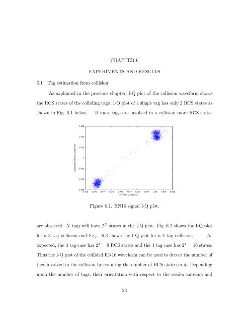
As explained in the previous chapter, I-Q plot of the collision waveform shows<br />
the RCS states of the colliding <strong>tag</strong>s. I-Q plot of a single <strong>tag</strong> has only 2 RCS states as<br />
shown in Fig. 6.1 below. If more <strong>tag</strong>s are involved in a collision more RCS states<br />
Figure 6.1. RN16 signal I-Q plot.<br />
are observed. N <strong>tag</strong>s will have 2 N states in the I-Q plot. Fig. 6.2 shows the I-Q plot<br />
for a 3 <strong>tag</strong> collision and Fig. 6.3 shows the I-Q plot for a 4 <strong>tag</strong> collision. As<br />
expected, the 3 <strong>tag</strong> case has 2 3 = 8 RCS states and the 4 <strong>tag</strong> case has 2 4 = 16 states.<br />
Thus the I-Q plot of the collided RN16 waveform can be used <strong>to</strong> detect the number of<br />
<strong>tag</strong>s involved in the collision by counting the number of RCS states in it. Depending<br />
upon the number of <strong>tag</strong>s, their orientation with respect <strong>to</strong> the reader antenna and<br />
23