Final Fairing & Finishing - WEST SYSTEM Epoxy
Final Fairing & Finishing - WEST SYSTEM Epoxy
Final Fairing & Finishing - WEST SYSTEM Epoxy

Create successful ePaper yourself
Turn your PDF publications into a flip-book with our unique Google optimized e-Paper software.
002-740<br />
<strong>Final</strong> <strong>Fairing</strong> & <strong>Finishing</strong><br />
Techniques for fairing surfaces with <strong>WEST</strong> <strong>SYSTEM</strong> ® <strong>Epoxy</strong><br />
and a guide to finish coatings<br />
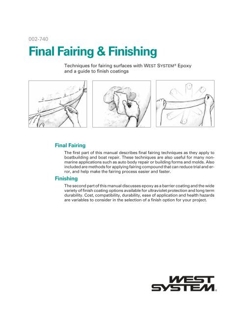
<strong>Final</strong> <strong>Fairing</strong><br />
The first part of this manual describes final fairing techniques as they apply to<br />
boatbuilding and boat repair. These techniques are also useful for many nonmarine<br />
applications such as auto body repair or building forms and molds. Also<br />
included are methods for applying fairing compound that can reduce trial and error,<br />
and help make the fairing process easier and faster.<br />
<strong>Finishing</strong><br />
The second part of this manual discusses epoxy as a barrier coating and the wide<br />
variety of finish coating options available for ultraviolet protection and long term<br />
durability. Cost, compatibility, durability, ease of application and health hazards<br />
are variables to consider in the selection of a finish option for your project.
Catalog No. 002-740<br />
<strong>Final</strong> <strong>Fairing</strong> & <strong>Finishing</strong><br />
Techniques for fairing surfaces with <strong>WEST</strong> <strong>SYSTEM</strong> ® <strong>Epoxy</strong><br />
and a guide to finish coating<br />
6th Edition—June 2010<br />
The techniques described in this manual are based on the handling characteristics and<br />
physical properties of <strong>WEST</strong> <strong>SYSTEM</strong> <strong>Epoxy</strong> products. Because physical properties of<br />
resin systems and epoxy brands vary, using the techniques as described this publication<br />
with coatings or adhesives other than <strong>WEST</strong> <strong>SYSTEM</strong> is not recommended. Refer to the<br />
current <strong>WEST</strong> <strong>SYSTEM</strong> User Manual & Product Guide for complete product information,<br />
and safety and handling guidelines.<br />
The information presented herein is believed to be reliable as of publication date, but<br />
we cannot guarantee its accuracy in light of possible new discoveries. Because West<br />
System Inc. cannot control the use of <strong>WEST</strong> <strong>SYSTEM</strong> products in customer possession,<br />
we do not make any warranty of merchantability or any warranty of fitness for a particular<br />
use or purpose. In no event, shall West System Inc. be liable for incidental or consequential<br />
damages.<br />
<strong>WEST</strong> <strong>SYSTEM</strong>, 105 <strong>Epoxy</strong> Resin, 205 Fast Hardener, 206 Slow Hardener, G/5, G/flex,<br />
410 Microlight and Six10 are registered trademarks of West System Inc. Scarffer, 209<br />
Extra Slow Hardener, 207 Special Clear Hardener and 422 Barrier Coat Additive are<br />
trademarks of West System Inc., Bay City, MI USA.<br />
Copyright © February 1989, February 1994, September 1997, October 2001, June<br />
2005, March 2010 by Gougeon Brothers, Inc.<br />
Published by Gougeon Brothers, Inc., Bay City, MI USA. All Rights reserved. No part<br />
of the contents of this book may be reproduced or transmitted in any form or by any<br />
means without the written permission of the publisher.
About this manual<br />
This manual is designed to be used along with the <strong>WEST</strong> <strong>SYSTEM</strong> ® User Manual and<br />
Product Guide. If you do not have previous experience with epoxy, read and become<br />
familiar with the safety, handling and basic techniques presented in the <strong>WEST</strong> <strong>SYSTEM</strong><br />
User Manual and Product Guide, available free from West System Inc. and and available<br />
at www.westsystem.com. Follow all safety precautions described in these manuals<br />
and on product labels. Structural repairs should be completed before beginning final<br />
fairing. For information on repairing fiberglass and wooden structures, refer to<br />
002-550 Fiberglass Boat Repair & Maintenance or 002-970 Wooden Boat Restoration<br />
& Repair, published by Gougeon Brothers, Inc. If you have specific questions about the<br />
use of <strong>WEST</strong> <strong>SYSTEM</strong> <strong>Epoxy</strong>, contact the <strong>WEST</strong> <strong>SYSTEM</strong> Technical Staff:<br />
West System Inc.<br />
P.O. Box 665<br />
Bay City, MI 48707 USA<br />
866-937-8797<br />
www.westsystem.com<br />
Table of Contents<br />
Introduction . . . . . . . . . . . 1<br />
<strong>Final</strong> <strong>Fairing</strong> . . . . . . . . . . . . 1<br />
Establishing a fair level . . . . . . . . . 2<br />
Removing high areas . . . . . . . . . 3<br />
Filling low areas . . . . . . . . . . 4<br />
Standard method . . . . . . . . . . 5<br />
Notched trowel method . . . . . . . . 6<br />
Guide methods . . . . . . . . . . 7<br />
Batten guide method . . . . . . . . . 8<br />
Template guide method . . . . . . . . 9<br />
Template transfer . . . . . . . . . . 12<br />
Local fairing . . . . . . . . . . . 13<br />
<strong>Finishing</strong>. . . . . . . . . . . . . 13<br />
<strong>Epoxy</strong> barrier coating . . . . . . . . . 13<br />
Re-coating . . . . . . . . . . . 15<br />
<strong>Final</strong> surface preparation . . . . . . . . . 16<br />
Finish coatings . . . . . . . . . . . 16<br />
Characteristics of coatings . . . . . . . . 17<br />
Coating types. . . . . . . . . . . 19<br />
<strong>Final</strong> notes . . . . . . . . . . . 21<br />
Appendix A Tools and materials . . . . . . . 22<br />
Appendix B Lofting foil shapes for rudders and keels . . . 25<br />
Appendix C Problem solving . . . . . . . . 26<br />
Appendix D Index . . . . . . . . . . 29
Introduction<br />
No matter how well a boat is built, the builder’s skill is often judged on the boat’s outer<br />
fraction of an inch. When you see an undistorted reflection in a flawless paint job over<br />
a perfectly faired surface, you see a reflection of the builder’s skill, attention to detail<br />
and pride in workmanship. <strong>Final</strong> fairing and finishing are more than the final steps in<br />
the boatbuilding process. They are two of the fine arts of boatbuilding.<br />
The first part of this manual describes final fairing techniques as they apply to<br />
boatbuilding, and boat repair and restoration projects such as modifying a boat’s shape<br />
and function, restoring or improving a hull’s efficiency, or simply improving a boat’s<br />
appearance. The value of these techniques is not limited to boatbuilding. <strong>WEST</strong><br />
<strong>SYSTEM</strong> epoxy’s versatility and ability to bond to many different materials permits<br />
these techniques to be used in a variety of non-marine applications as well, from auto<br />
body repair to building forms and molds.<br />
These techniques are intended to reduce trial and error, and help make the final fairing<br />
process easier and faster by putting some science back into the art of fairing. However,<br />
achieving the perfectly faired surface still requires a critical attitude and a discriminating<br />
eye.<br />
The second part of this manual discusses epoxy as a barrier coating and a base for the<br />
finish system. <strong>WEST</strong> <strong>SYSTEM</strong> epoxy is an excellent base for paints and clear finishes, but<br />
on surfaces exposed to sunlight it needs ultraviolet (UV) protection for long term durability.<br />
A wide variety of commercially available paints and clear finishes will protect<br />
epoxy surfaces from the effects of UV. Some may be more suited to your project than<br />
others. Cost, compatibility, durability, ease of application and health hazards are also<br />
variables to consider in the selection of a coating.<br />
Because of the wide range of coating types, the variability of different brands, and the<br />
continuing advancement of coating technology, this section can only provide a general<br />
guide to the types of finishes. Coating terminology and product names can vary between<br />
manufactures, suppliers, and applicators, especially when referring to newer<br />
types of coatings. Read and follow manufacturers’ recommendations and application<br />
instructions for specific coatings. If you are unsure of a product’s compatibility or suitability,<br />
test the product on a representative sample before coating your project.<br />
<strong>Final</strong> <strong>Fairing</strong><br />
<strong>Final</strong> <strong>Fairing</strong> 1<br />
<strong>Fairing</strong> is the process of creating or shaping a smooth line, edge or surface, free of hollows<br />
or bumps. In traditional boatbuilding, fairing is first employed during the layout<br />
of the many individual lines of the boat on the lofting floor, or on the less traditional<br />
computer aided design (CAD) program. Each line is described by a series of plotted<br />
points. If one or more points is out of place, the line will not be true or accurate. If the<br />
line connecting these points does not flow smoothly or continuously, the line will not<br />
be “fair”. Lines must be both true and fair. Plotting the points accurately requires careful<br />
measurement with a ruler, but the smoothness of a line flowing through those<br />
points is often best measured by eye. This is the conjunction of science and art in<br />
boatbuilding.<br />
Properly lofted lines are then transferred to the profiles of the keel, bulkheads and<br />
frames. When assembled and properly aligned, their combined two-dimensional profiles<br />
describe the three-dimensional shape of the hull. If one or more of these components<br />
is out of place or unfair, the surface of the planking installed over them will not<br />
be fair.
<strong>Final</strong> <strong>Fairing</strong> 2<br />
The skillful boatbuilder will keep the lines of the hull and deck surface both true and<br />
fair through all stages of construction, thereby reducing the amount of final fairing required.<br />
Up to a point, fairness is necessary to produce a hull that offers minimum resistance<br />
as it moves through the water. Beyond a certain point, the degree of fairness is a<br />
matter of personal pride and a reflection of the builder’s craftsmanship.<br />
<strong>Final</strong> fairing is the last step in the fairing process. Its purpose is to correct any unevenness<br />
or flaws in the surface after the structure is completed. <strong>Final</strong> fairing begins with<br />
overall fairing, that is removing major high spots and/or filling low spots over broad areas.<br />
Then local fairing removes any remaining minor surface irregularities and makes<br />
the surface texture smooth to the touch.<br />
Establishing a fair level<br />
First consider the overall or general fairness of the surface, rather than individual or local<br />
high or low spots.<br />
Imagine the earth without any water on it and you had the job of fairing it to a perfect<br />
sphere. You would have several options:<br />
1. You could grind all of the land down to the lowest elevation (the bottom of the lowest<br />
ocean trench).<br />
2. You could fill everything up to the highest elevation (the peak of Mt. Everest).<br />
3. You could grind all of the land down to a specific level or elevation (sea level for example),<br />
and then fill the remaining low areas up to that level.<br />
On a smaller scale, a fair surface on a boat hull is often achieved by removing material<br />
from highest areas until you reach a critical or convenient level or elevation, and then<br />
filling the remaining low areas up to that level (Figure 1).<br />
The question of where to establish that level may be determined by the type and size of<br />
the boat, how accurately you want to maintain the hull’s lines, the hardness or<br />
machinability of the surface material, the existing fairness and volume of material to be<br />
removed or added, skin thickness, whether the surface is to be finished clear or<br />
painted, the tools or equipment available, and your level of skill and endurance.<br />
If you are fairing a wooden boat that you want to finish natural, such as a stripper canoe,<br />
you have little choice but to remove all of the high areas and establish the fair level<br />
at the lowest point on the surface, (option 1). This emphasizes the importance of keeping<br />
the hull fair throughout construction. If you are fairing a stripper canoe, for exam-<br />
1. Grind down to the fair level<br />
2. Fill up to the fair level<br />
3. Grind down then fill up to the fair level<br />
Figure 1 Unfair surfaces can be 1. Ground down to the lowest level, 2. Filled to the<br />
highest level, 3. Ground to a specific elevation and filled to that level.
ple, and one of the frames is 5 16" too high, you would have to alter the shape of the hull<br />
to avoid sanding a hole through 1 4" planking.<br />
If you are fairing a hard surface like a fiberglass, aluminum or steel hull, or a lead keel,<br />
removing a lot of material is impractical. You are pretty much limited to filling the low<br />
areas and establishing the level near or above the highest point on the surface, (option<br />
2). Many steel and aluminum boats are built this way. A layer of fairing compound is<br />
applied over the completed hull and all of the fairing takes place in the easy-to-sand<br />
fairing compound outside of the hull’s metal surface.<br />
Removing high areas<br />
The first task in overall fairing is locating the high and low areas. Developing a good<br />
eye or feel for finding high or low areas may come naturally or with practice and trial<br />
and error. Whether you develop a good eye or not, a batten or chalk stick is an indispensable<br />
fairing tool. See Appendix A, page 23. A batten will also help you develop your<br />
eye by providing an accurate backup measurement to check against your eye and hand<br />
measurements.<br />
As you hold the batten firmly against the surface, it will rest on the high spots and<br />
bridge the low areas. By moving the batten to different positions in an area, you should<br />
be able to get an idea of the surface topography.<br />
Gaps under batten at low areas<br />
Chalk rubs off on high areas<br />
Figure 2 A batten will reveal the high and low areas, and the difference<br />
between them. Chalk applied to the batten will rub off on the high spots.<br />
<strong>Final</strong> <strong>Fairing</strong> 3<br />
Mark the high spots by applying carpenters chalk to the face of a batten, and rubbing<br />
the batten over the surface. The chalk will be deposited on the high spots (Figure 2).As<br />
you take the high spots down to fair, you can use the chalk stick as often as you like to<br />
monitor your progress. Continue removing high spots until you are satisfied with the<br />
fairness.<br />
Methods for removing high spots depend on the material and how much of it needs to<br />
be removed. For aluminum, steel, fiberglass or other hard materials, a heavy duty disc<br />
sander may be the most practical tool to use. For rough fairing on wood or cured fairing<br />
compound, a plane, disc sander, belt sander or air file can be used, but some skill<br />
and experience are required to avoid sanding too deep. The short contact area of these<br />
tools also increases the risk of removing material from the wrong areas.<br />
Warning! The dust generated from fairing can make it the dirtiest and one of the most hazardous<br />
operations in the boat shop. An appropriate dust mask and eye protection should<br />
always be worn. Wear appropriate protective clothing and keep your work area well ventilated.<br />
Refer to the safety information in the <strong>WEST</strong> <strong>SYSTEM</strong> User Manual & Product Catalog<br />
and on all product labels. Read and follow all power tool safety information.
A long flexible sanding block, or fairing board, is the primary tool for overall fairing on<br />
wood and fairing compound. See Appendix A, page 23 for information on making fairing<br />
boards. The key word is long, especially at early stages. Working on the same principle as<br />
the batten, the sanding board should bend to the overall shape of the surface, but be long<br />
enough and stiff enough to bridge the low areas and knock down the high spots over a<br />
large area. A short sanding block and most power tools at this stage will simply follow<br />
the contours and remove material from the low areas as well as the high areas.<br />
We prefer aluminum oxide sandpaper as it seems to cut a wide range of materials, including<br />
cured epoxy/fairing material, better than other types of sandpaper. Zirconia<br />
alumina also cuts well and it wears longer. Stick sandpaper to boards and blocks with a<br />
feathering disc adhesive, or use adhesive backed sandpaper. Either will permit removal<br />
of the paper when replacement is needed. See Appendix A, page 22 for more information<br />
about abrasives.<br />
Begin your final fairing with 50 or 60-grit paper, concentrating on taking down the<br />
high spots over a broad area. Change sanding direction frequently and check your<br />
progress from time to time by eye or feel, or with a batten.<br />
When you are getting close to final fairness, switch to 80-grit paper. If you will be clear<br />
coating wood, begin to sand only in the direction of the grain to remove and avoid<br />
cross-grain scratches. Vary the angle you hold the board to avoid sanding in or creating<br />
a valley (Figure 3). As a final check, place the batten in different positions on the surface.<br />
The batten should make solid contact everywhere on the surface with no voids<br />
anywhere along its length.<br />
Figure 3 Vary the angle of the board (0°,45°,90°) to avoid sanding in or creating a valley.<br />
Filling low areas<br />
<strong>Final</strong> <strong>Fairing</strong> 4<br />
If you will be painting the surface, you may decide that it is more practical at some<br />
point in the process to fill the remaining low areas with fairing compound rather than<br />
continue sanding high areas. Often the decision to begin filling low areas is determined<br />
simply by the volume of material remaining in the high areas and the time and effort<br />
required to remove it.<br />
Four methods for filling low areas may be used depending on the area or volume to be<br />
filled and the degree of fairness and accuracy required. A large job may have applications<br />
for all of these methods.
The standard method relies on your eye or a batten to judge the application and removal<br />
of the fairing compound. It is the method most often used, but requires some experience<br />
and/or a good eye to fair very large areas efficiently.<br />
The notched trowel method is a variation of the standard method that makes it easier<br />
to sand larger areas. It also relies on your eye to judge the application of the fairing<br />
compound.<br />
The batten guide method involves more steps than the standard or notched methods,<br />
but offers a more efficient application of the fairing compound.<br />
The template guide method, similar to the batten guide method, is useful when the surface<br />
must describe a specific shape very accurately. It is often used to produce accurately<br />
faired keel and rudder foils.<br />
Standard method<br />
This method requires you to judge the application of the fairing compound visually<br />
and with the aid of a batten. You may need to repeat the process several times to reach a<br />
fair surface; however, you should become more efficient with practice.<br />
1. Be sure surfaces to be coated are clean, dry and sanded. Clean contaminated fiberglass<br />
or metal surfaces with solvent before sanding. Sand or grind metal surfaces with a<br />
coarse grit to remove oxidation and provide a texture for the epoxy to key into. Before<br />
coating, identify the low areas by feel or with a batten and estimate the volume of filler<br />
required to slightly overfill the void.<br />
2. Wet out the surface with resin/hardener mixture (Figure 4). It is a good idea to coat the<br />
entire surface or repair area at this time. When coating metal surfaces, you can increase<br />
the ultimate adhesion of the fairing material by sanding the wet epoxy mixture into the<br />
metal with coarse sandpaper. To avoid sagging, allow the wet-out coat to gel before applying<br />
the fairing compound. Sanded epoxy surfaces do not need to be wet out.<br />
Figure 4 Wet out the surface with resin/hardener mixture. To<br />
avoid sags, allow the wet-out coat to gel before applying fairing<br />
compound.<br />
<strong>Final</strong> <strong>Fairing</strong> 5<br />
3. Prepare a fairing compound with epoxy and either 407 Low-Density or 410<br />
Microlight filler. Dispense no more than 1/4 of a pot full of resin/ hardener to allow<br />
room for filler. Mix the resin/ hardener together thoroughly. Stir in filler until it<br />
reaches a non-sagging, peanut butter consistency.<br />
4. Trowel the mixture on with a plastic spreader. Fill the low areas to just above the fair<br />
level so the fairing compound can be sanded back down to fair without having to be refilled.<br />
Use the spreader to smooth the compound as close as possible to the desired<br />
shape to avoid excessive sanding after the mixture has cured (Figure 5). The contour of
Figure 5 Use a spreader to apply fairing compound, and<br />
slightly overfill the area. Shape the mixture to blend with<br />
the surrounding contour.<br />
small areas can often be judged by eye. When filling voids over ½" deep, it’s best to apply<br />
the mixture in two or more layers to avoid excessive heat build up from the exothermic<br />
curing reaction. Apply the second layer after the first layer has partially cured.<br />
5. Use a batten to help shape larger areas. After slightly overfilling the area with a<br />
spreader, slowly drag a batten across the filled area while bending it to the contour of<br />
the surrounding fair areas (Figure 6). A slight “Z” or back and forth motion of the batten<br />
can help to reduce the drag of the fairing compound. Allow the fairing compound<br />
to cure thoroughly before sanding.<br />
6. With the application of the fairing compound, low areas have now become high areas.<br />
Sand these areas down to fair using the techniques for overall fairing. Continue to<br />
check for fairness as you sand.<br />
7. Fill and sand any low areas you find as many times as necessary until you are satisfied<br />
with the overall fairness. When refilling areas, it is not necessary to re-coat the surface<br />
with unthickened epoxy unless you’ve sanded through the first coating into the<br />
original surface.<br />
Notched trowel method<br />
Figure 6 On large areas, use a batten to shape the<br />
compound after applying it with a spreader.<br />
<strong>Final</strong> <strong>Fairing</strong> 6<br />
When fairing large areas that require a lot of filling, such as a steel or aluminum hull, it<br />
may be easier and more economical to divide the process into two stages. The notched<br />
trowel method helps to eliminate much of the sanding time required during the early<br />
part of the fairing process by reducing the volume of fairing compound to be sanded.<br />
The first layer of fairing compound is applied with a notched spreader to leave a pattern<br />
of ridges. Before starting the procedure, use a batten to determine the depths of<br />
the areas to be filled and cut the length of the notches in the spreader to match the<br />
deepest area.<br />
1. Be sure surfaces to be coated are clean, dry and sanded. Clean contaminated fiberglass<br />
or metal surfaces with solvent before sanding. Sand or grind metal surfaces with a<br />
coarse grit to remove oxidation and provide a texture for the epoxy to key into.<br />
2. Wet out the surface with resin/hardener mixture (Figure 4). Coat the entire surface or<br />
repair area at this time. To avoid sagging, allow the wet-out coat to gel before applying<br />
the fairing compound. Sanded epoxy surfaces do not need to be wet out.<br />
3. Prepare a fairing compound with epoxy and either 407 Low-Density or 410<br />
Microlight filler. Dispense no more than 1/4 of a pot full of resin/ hardener to allow<br />
room for filler. Mix the resin/hardener together thoroughly. Stir in filler until it<br />
reaches a stiff, peanut butter consistency.
Figure 7 Apply the fairing compound with the<br />
notched spreader. Control the height of the<br />
ridges by the angle you hold the spreader.<br />
4. Apply the fairing compound with the notched spreader (Figure 7). Hold the spreader<br />
at a higher angle to leave deeper ridges on the lowest areas and at a lower angle to leave<br />
shallower ridges on the higher areas. The tops of the ridges should be slightly above the<br />
finished fair level. Allow the fairing compound to cure thoroughly.<br />
5. Sand the ridges fair. The ridges of fairing compound are much easier to sand than solid<br />
material.<br />
6. Prepare the surface for bonding. Use a wire brush to rough up the exposed surface of<br />
the fairing compound within the grooves.<br />
7. Trowel a second layer of fairing compound over the surface to fill the grooves (Figure<br />
8). Use a smooth-edged spreader held firmly against the surface to drag away excess<br />
compound, leaving a smooth surface flush with the faired ridges. Mix the fairing compound<br />
for the second layer to the same density as the first layer. Allow the fairing compound<br />
to cure thoroughly.<br />
8. Sand the surface smooth. It should require only minor local fairing before barrier coating<br />
and finishing as described in the <strong>Finishing</strong> section.<br />
Guide methods<br />
<strong>Final</strong> <strong>Fairing</strong> 7<br />
Figure 8 Trowel a second layer of fairing<br />
compound over the surface to fill the grooves<br />
after the ridges have been sanded fair.<br />
The standard method for filling low areas is often one of trial and error. Excess fairing<br />
material is applied, then removed and often reapplied and removed until a fair level is<br />
reached. Skill and experience are required to accurately apply the fairing compound<br />
and cut it away to produce a fair surface with a minimum of waste and effort. The batten<br />
guide or template guide methods allow you to accurately fill low areas over a very<br />
large area, even entire hulls, using a minimum of material and requiring less sanding<br />
time.<br />
Ridges of fairing compound are applied across the unfair surface and a batten or templates<br />
are pressed into the ridges. When cured, the cast batten or template profiles provide<br />
guides for the application of the remaining fairing compound. A batten laid across<br />
the guides accurately controls the level of the fairing compound applied between the<br />
guides, in much the same way concrete is leveled between two forms to build a sidewalk.<br />
The number of guides required depends on the size and shape of the surface. On<br />
flat or simple curved areas like a hard chined hull or a fin keel, one to three guides may<br />
be enough to describe the surface. On curved surfaces, a number of closely spaced<br />
guides may be necessary to accurately describe surface. A single guide may be placed in<br />
an unfair area for general reference or many may be applied over an entire hull in a<br />
regular grid pattern for more precise application.
Batten guide method<br />
The batten guide method uses a flexible batten to cast an impression in the ridge of fairing<br />
compound. The resulting profile is determined by the stiffness of the batten and the<br />
batten’s points of contact with the unfair surface. The batten should be a suitable stiffness<br />
for the curve of the fairing area. This procedure may require at least two people to<br />
support and accurately position the batten.<br />
1. Prepare the area for bonding. Remove all paint. Wire brush the entire surface of external<br />
keels to remove any contamination and to expose fresh iron or lead. Sand the surface<br />
of internal keels or hulls to remove loose fillers and gelcoat and expose solid<br />
fiberglass laminate. Dry the surface if necessary, using a hot air gun, hair dryer or heat<br />
lamp.<br />
2. Determine and mark the locations for the guides. If you are fairing a curved surface like<br />
a hull, you may need to provide at least three parallel profile guides to describe the<br />
curve. Curves with a smaller radius and complex shapes may require more or closer<br />
spaced guides. Use a long batten to locate the high spots and determine how much fairing<br />
compound will be required to fill the low areas to a level above the bottom of the<br />
batten. Mark the high spots where the batten touches the surface (Figure 9).<br />
3. Wet out a 2"–3" wide strip at each guide location. If you are working with a lead or<br />
metal keel, wire brush the surface while the epoxy is still wet for a better bond. Allow<br />
the epoxy to gel.<br />
Figure 9 Use a long batten to locate the high and low areas<br />
and judge the amount of fairing compound required.<br />
<strong>Final</strong> <strong>Fairing</strong> 8<br />
Figure 10 Use a spreader notched to the shape of the ridge<br />
to shape the mixture.<br />
4. Apply a 1"–2" wide ridge of fairing compound to the surface at each guide location. Use<br />
the same mixture of epoxy/407 or 410 filler, thickened to a stiff, peanut butter consistency,<br />
that will be used to fill between the guides. Trowel on the fairing mixture with a<br />
plastic spreader, and then use a spreader notched to the shape of the ridge to shape the<br />
mixture (Figure 10). Cut the notch deep enough to equal the height of the ridge at the<br />
lowest area of the surface. Tilt the spreader as necessary to adjust the height.<br />
5. Cover the ridges with strips of 879 Release Fabric. Press the fabric lightly to the surface.<br />
Do not press hard enough to flatten the ridges. Tape the fabric in place if necessary.<br />
6. Press the batten into the ridge of thickened epoxy until it contacts the high spots in the<br />
surface. Push the batten into the ridge. Apply pressure only where the batten touched<br />
the high spot you marked earlier (Figure 11). If an area of the epoxy ridge is too low to<br />
contact the batten, squeeze the sides of the epoxy ridge together under the fabric so<br />
that it is forced up to contact the batten. When you’re satisfied, carefully remove the<br />
batten without disturbing the ridge or the fabric. Repeat the process for each batten<br />
guide and allow the epoxy mixture to cure thoroughly.
Release fabric Guide<br />
Figure 11 Push the batten into the ridge. Apply<br />
pressure only where the batten touched the high<br />
spot you marked earlier.<br />
7. Remove the release fabric strips and mark the center of the batten impression with a<br />
permanent felt marker to act as a sanding indicator. Sand the ridges on either side of<br />
the batten impression flush with the center. Avoid sanding into the profile. You should<br />
be left with smooth bands of fairing compound that will be used as guides to accurately<br />
apply the remaining fairing material.<br />
8. Wet out the surface between the guides with epoxy. Allow the coating to gel.<br />
9. Apply a layer of the epoxy/407 or 410 filler to the surfaces between the profile guides.<br />
Use the same filler and filler consistency that was used to make the guides. Use a plastic<br />
spreader to apply and smooth the mixture slightly higher than the guides.<br />
10. Shape the fairing mixture before it begins to gel, using an appropriate batten. With the<br />
batten held perpendicular to and pressed to the guides, drag it along the guides. The<br />
batten will follow the guide profiles, removing excess mixture and leaving the surface<br />
between the guides smooth and level with the guides (Figure 12). To give yourself adequate<br />
working time in warmer temperatures, use 206 or 209 Hardener or fill just one<br />
section at a time. Allow the fairing mixture to cure thoroughly.<br />
11. Sand the cured surface fair, being careful not to sand through the indicator you marked<br />
on the top of the guide. Use battens to check for fairness in both directions. Fill any remaining<br />
low areas again when cured. Repeat as necessary until you are satisfied with<br />
the shape and fairness of the surface.<br />
12. Repeat the process on all areas to be faired. When you are satisfied with the fairness<br />
and smoothness, apply epoxy barrier coats and finish as described in the <strong>Finishing</strong><br />
section.<br />
A variation of the previous method is to apply fairing compound to a large area. Lay<br />
strips of release fabric on the surface in several locations, and then press a batten to the<br />
surface at each location before the mixture begins to gel. If a thick enough layer of fairing<br />
compound is applied, the batten will leave a fair profile indentation in the fresh<br />
mixture. When the mixture cures, remove the strips and use the batten profiles as sanding<br />
guides. This method reduces the number of steps in the procedure, but requires<br />
more sanding.<br />
Template guide method<br />
<strong>Final</strong> <strong>Fairing</strong> 9<br />
Figure 12 Drag the batten along the guides,<br />
removing excess mixture and leaving the surface<br />
between the guides smooth and level with the<br />
This method is similar to the batten guide method except that a template describing a<br />
specific profile is used to shape the guide rather than a batten. Although a batten-generated<br />
profile may be fair, the high points of the unfair surface will determine the profile.<br />
Template profiles may be lofted from offsets (See Appendix B) or transferred from<br />
an existing surface (See Template Transfer following this section).
Root<br />
Midpoint<br />
Tip<br />
Waterline<br />
Plywood template<br />
<strong>Final</strong> <strong>Fairing</strong> 10<br />
Figure 13 Obtain the profiles for three locations on the keel: the root (top of the keel near the hull attachment<br />
point), the midpoint and the tip of the keel.<br />
One of the best uses of this method is to improve the efficiency of rudders and centerboards.<br />
The following example describes the use of templates to establish precise foil<br />
shaped guides on the surface of a keel and the application of fairing compound between<br />
the guides. Although the procedure describes keel templating, the same procedure<br />
applies to rudders or any other lofted shape. This procedure may require at least<br />
two people to support and accurately position the templates.<br />
1. Transfer the full size profiles to ½" A/C-grade plywood (Figure 13). Cut out the three<br />
templates with a band saw or saber saw and sand the edges of the foil shape carefully to<br />
eliminate any bumps or unfairness. Mark the keel’s centerline on each end of the template.<br />
Seal the profile edge of the templates with a coat of epoxy and sand them smooth<br />
after the epoxy cures.<br />
2. Prepare the area for bonding. Remove all paint. Wire brush the entire surface of external<br />
keels to remove any contamination and to expose fresh iron or lead. (Be sure to<br />
wear an appropriate dust mask, especially when sanding or wire brushing lead.) Sand<br />
the surface of internal keels (or hulls) to remove loose fillers and gelcoat and expose<br />
solid fiberglass laminate. Dry the keel using a hot air gun, hair dryer or heat lamp.<br />
Locate and mark the centerline on the leading edge and, if necessary, the trailing edge<br />
of the keel. Mark the template locations on both sides of the keel. Check the keel’s profile<br />
with the templates to locate any high spots and to gauge how much fairing compound<br />
to apply to the low areas. Grind down or plane off excessive high spots.<br />
3. Wet out 2"–3" wide strips at the template locations with epoxy. If you are working with<br />
a lead or metal keel, wire brush the surface while the epoxy is still wet for a better bond.<br />
Allow the epoxy to gel.<br />
4. Apply a 1"–2" wide ridge of epoxy/407 or 410 filler mixture (thickened to a stiff, peanut<br />
butter consistency) to the surface at each template location. Use a plastic spreader<br />
to trowel on the fairing mixture slightly thicker than the finished profile. A spreader<br />
notched to the shape of the ridge is helpful to shape the mixture.<br />
5. Cover the ridges with a strips of 879 Release Fabric to keep the fairing mixture from<br />
sticking to the template. Lightly press the release fabric to the ridge. Do not press hard<br />
enough to flatten the ridge.<br />
6. Push the templates into the soft mixture to make an impression of the exact keel profile<br />
at each template location. To gauge the depth of the impression (height of the profile),<br />
push the template into the mixture until the centerlines marked on the template match<br />
the centerlines marked on the leading and trailing edges of the keel (Figure 14). Ifan<br />
area of the ridge is too low to contact the template when it is properly aligned, squeeze
<strong>Final</strong> <strong>Fairing</strong> 11<br />
the material under the release fabric upward so it comes in contact with the template.<br />
When you’re satisfied, carefully remove the template, leave the release fabric in place,<br />
and allow the mixture to cure thoroughly.<br />
7. Remove the release fabric and mark the center of the template impression with a permanent<br />
felt marker to act as a sanding guide. Sand the ridges on either side of the template<br />
impression flush with the profile. Avoid sanding into the profile. You should be<br />
left with smooth bands of fairing compound at the root, midpoint and tip of the keel<br />
that will be used as profile guides to accurately apply the remaining fairing material.<br />
Use the templates to check the profiles and sand or add filler to the profile as necessary<br />
to match the template.<br />
8. Wet out the surface between the guides with epoxy. Allow the coating to gel.<br />
9. Mix enough epoxy/407 or 410 fairing compound to fill the area between two of the<br />
profile guides. Use the same filler and filler consistency used to make the guides. With a<br />
plastic spreader or custom spreader, apply the mixture to the middle area of the foil.<br />
Leave the mixture higher than the guides. See Appendix A for information on mixing<br />
and applying large quantities of fairing compound.<br />
Release<br />
fabric<br />
Template<br />
Match keel<br />
centerline<br />
Figure 14 Push the template into the mixture until<br />
the centerlines marked on the template match the<br />
centerlines marked on the leading and trailing edges<br />
of the keel<br />
1½" PVC pipe<br />
Release fabric<br />
Guides<br />
Figure 15 Using a length of 1½" diameter PVC pipe,<br />
shape the fairing mixture flush with the guides by<br />
rolling the pipe back and forth on the guides, as you<br />
would a rolling pin.<br />
10. Lay a precut piece of release fabric over the fairing compound. The fabric should be<br />
large enough to cover the entire area from guide to guide. Using a length of 1½" diameter<br />
PVC pipe cut to span two of the guides, shape the fairing mixture flush with the<br />
guides. Beginning in the middle of the foil, roll the pipe back and forth, as you would a<br />
rolling pin, forcing fairing compound under the release fabric toward the leading and<br />
trailing edges of the foil (Figure 15). Adjust the angle of the pipe as you approach the<br />
edges of the foil to finish with the pipe parallel to the leading and trailing edges. With<br />
the proper amount of fairing compound, a small amount of excess will squeeze from<br />
the leading and trailing edge. To give yourself adequate working time in warmer temperatures,<br />
use 206 or 209 Hardener. Allow the fairing mixture to cure thoroughly.<br />
11. Remove the release fabric. Repeat the process on the remaining areas. Fill any large remaining<br />
low areas using the same procedure after the fairing compound has cured. Repeat<br />
as necessary until you are satisfied with the shape and fairness of the surface.<br />
12. Sand the cured surface as necessary. It should require only minor local fairing. When<br />
you are satisfied with the fairness and smoothness, apply an epoxy barrier coat and finish<br />
as described in the <strong>Finishing</strong> section.
Plywood<br />
template<br />
Template transfer<br />
<strong>Final</strong> <strong>Fairing</strong> 12<br />
Template transfer is a method of casting a template profile of an existing shape, using<br />
its surface as a mold. The technique has a variety of uses. In the keel fairing situation<br />
above, the transfer method can be used to transfer the shape of one side of an existing<br />
keel to the opposite side to make the keel symmetrical or it can be used to transfer the<br />
shape of one keel or hull to another. The technique can also be used to cast an accurate<br />
hull profile to build bunks for cradles or trailers, or any similar situation that requires a<br />
shape to be accurately duplicated. The following procedure describes the transfer of a<br />
keel foil shape. For accuracy, templates should be transferred in at least two or three<br />
locations on the keel.<br />
1. Determine the template transfer locations on the keel. To prevent the template from<br />
bonding to the keel, tape a strip of plastic over the area to be cast. (A smooth surface<br />
may be waxed to prevent bonding. Apply several coats of paste wax to act as a mold release.<br />
Be sure the surface has no recesses that would allow the epoxy to “key” into the<br />
surface.)<br />
2. Prepare a rough plywood template scribed to within 1 4" of the profile you wish to transfer<br />
(Figure 16). Cut the template from 3 8"or 1 2" plywood or particle board several<br />
inches longer than the foil. Prepare a method to clamp or brace the template in position<br />
against the surface.<br />
Figure 16 Prepare a rough plywood template scribed<br />
to within 1/4" of the profile you wish to transfer.<br />
Hold the<br />
template in<br />
place with tape<br />
until epoxy cures<br />
Figure 17 Press the template in place against the<br />
surface until the thickened mixture makes contact<br />
with the surface everywhere along the profile.<br />
3. Wet out the profile edge of the plywood (the edge facing the surface) with epoxy. Apply<br />
a bead of epoxy/406 or 404 mixture (thickened to a stiff, peanut butter consistency)<br />
to the profile edge of the plywood. The bead should be high enough to bridge<br />
any gaps between the template and the foil.<br />
4. Press the template in place against the surface until the thickened mixture makes contact<br />
with the surface everywhere along the profile (Figure 17). Use duct tape or masking<br />
tape to brace the template in position. Fill in any gaps or displaced mixture and<br />
allow the mixture to cure thoroughly.<br />
5. Carefully mark the leading and trailing edge centerlines on the template. Remove the<br />
clamps or braces. Remove the template from the surface. Sand the ridges that squeezed<br />
from the edge to make both faces of the plywood smooth. Repeat the procedure in the<br />
other transfer locations.
Local fairing<br />
When the difference between high and low areas is reduced by overall fairing (either by<br />
sanding down or filling up) or if your hull is generally fair to begin with, you can begin<br />
to concentrate on local fairing. Local fairing may be done with smaller sanding blocks,<br />
an orbital sander or an air file, using 80 grit sandpaper. It is not necessary to use sandpaper<br />
finer than 80 grit. Finer sanding will be done after the final coating. The object is<br />
to remove minor bumps or flaws and leave a smooth even texture over the entire surface.<br />
A shorter batten may be useful at the early stages of local fairing, but as you continue<br />
to eliminate the minor bumps, the batten should become less and less useful.<br />
This is the stage where you rely most on your eye to tell you what is fair. A light held<br />
close to the surface will cast long shadows that can help you detect slight surface variations.<br />
A clear bulb will cast sharper, more detailed shadows than a frosted or fluorescent<br />
bulb. Moving the light around to cast shadows from different directions will help<br />
you to locate bumps and voids and determine their height or depth. Fill voids with a<br />
thin layer of fairing compound if necessary. Rub your hand lightly over the surface in<br />
different directions to detect minor flaws that may not be apparent to your eye. As the<br />
surface becomes smoother, your fingertips may be the final judge of fairness. How far<br />
you continue with local fairing depends on your ability to detect flaws and how critical<br />
you are. Keep in mind that flaws that seem insignificant in a dull 80 grit finish will be<br />
more noticeable in a glossy finish, especially a dark colored glossy finish.<br />
After the fairing is completed, fiberglass fabric can be applied to the surface if desired.<br />
Fabric is often used to reinforce the structure and/or to provide abrasion resistance to<br />
the surface. Refer to the current <strong>WEST</strong> <strong>SYSTEM</strong> User Manual & Product Catalog for details<br />
on applying fiberglass cloth.<br />
Note! An epoxy barrier coat is required over sanded 410 Filler, if you are going to apply<br />
a solvented coating over the faired surface. Solvents in these coatings can affect 410<br />
Filler and result in print through. An epoxy barrier coat is recommended over sanded<br />
407 Filler to provide a consistent non-porous surface for finish coatings.<br />
<strong>Finishing</strong><br />
<strong>Finishing</strong> 13<br />
Applying an epoxy barrier coating is the last step in the fairing process and the first step<br />
in the finishing process. It is included in the <strong>Finishing</strong> section because an epoxy barrier<br />
coating is widely used as an interface between substrates and paints and varnishes even<br />
when fairing is not required. <strong>Epoxy</strong> bonds to a wide range of materials better than<br />
most finish coatings, it is compatible with a wide range of finish coatings, and the stability<br />
of an epoxy base helps finishes to last longer than they would over the substrate<br />
alone. The combination of an epoxy barrier coating topped with a durable finish<br />
coating provides a very effective finish system.<br />
<strong>Epoxy</strong> barrier coating<br />
The object of epoxy barrier coating is to build up an epoxy layer that protects the substrate<br />
from moisture. In doing so it stabilizes the substrate and provides a smooth stable<br />
base for the finish coating needed for UV protection.<br />
For an effective moisture barrier on most exterior surfaces, apply a minimum of three<br />
coats (about 10 mils) of <strong>WEST</strong> <strong>SYSTEM</strong> epoxy. Moisture protection will increase with<br />
additional coats, up to six coats or about a 20 mil thickness. A minimum of six coats is<br />
recommended on fiberglass hulls below the waterline.<br />
For best results, apply the coatings at or above room temperature. <strong>Epoxy</strong> will be thinner<br />
and spread more easily in warmer temperatures. Adding solvents to thin <strong>WEST</strong>
<strong>Finishing</strong> 14<br />
<strong>SYSTEM</strong> epoxy compromises its strength and moisture resistance, and is not recommended.<br />
Additives or pigments should not be added to the first coat.<br />
Disposable, thin urethane foam rollers, such as <strong>WEST</strong> <strong>SYSTEM</strong> 800 Roller Covers, are<br />
essential for applying epoxy. They allow you greater control over film thickness, leave<br />
less stipple than thicker nap-type roller covers, and the epoxy does not build up and<br />
cure as quickly on the cover. When used with an 801 Roller Frame, the covers may be<br />
cut into narrower widths to reach difficult areas or for coating long narrow surfaces<br />
like stringers.<br />
Complete all fairing and cloth application before beginning the final coating. Allow<br />
the temperature of porous surfaces to stabilize before coating. Otherwise, as the material<br />
warms up, air within the porous material may expand and pass from the material<br />
through the coating (out-gassing) and leave bubbles in the cured coating. For most situations<br />
that will be coated with an opaque finish, 105 Resin with 205 or 206 Hardener<br />
are recommended. When extra working time is needed in warmer temperatures, use<br />
105 Resin with 209 Extra Slow Hardener. For clear finishes over wood, use 207<br />
Special Coating Hardener<br />
While coating, remember that the thinner the film thickness, the easier it is to control<br />
the evenness of the film and avoid runs or sags in each coat. Thin coats also reduce the<br />
risk of trapped air bubbles in the coating. Fewer thick coats may take less time to apply,<br />
but will require more sanding and possibly more time overall.<br />
Apply an epoxy barrier coat as follows:<br />
1. Prepare the surface as necessary. After local fairing, the surface should be immediately<br />
ready for bonding. To avoid the possibility of surface contamination, begin the coating<br />
operation within 24 hours of final sanding.<br />
2. Mix only as much resin/hardener as you can apply during the open time of the mixture.<br />
Pour the mixture into a roller pan as soon as it is mixed thoroughly.<br />
3. Load the roller with a moderate amount of the epoxy mixture. Roll the excess out on<br />
the ramp part of the roller pan to get a uniform coating on the roller.<br />
4. Transfer the epoxy evenly to a small area. Roll lightly and randomly over an area approximately<br />
2' × 2' (Figure 18).<br />
5. Work the epoxy from thicker areas into thinner areas to spread it into a thin even film.<br />
Increase pressure slightly as the roller dries out. Expand the coverage area if necessary<br />
to thin out the film. Avoid working air into the coating by rolling too vigorously.<br />
6. Finish the area with long, light, even strokes to reduce roller marks. Overlap the previously<br />
coated area to blend both areas together.<br />
Figure 18 Using a foam roller, apply the epoxy and spread<br />
it into a thin even film.<br />
Figure 19 Tip off each batch, as soon as it is applied, by<br />
dragging a roller cover brush lightly over the wet surface.
7. Coat as many of these small working areas as you can with each batch. If a batch begins<br />
to thicken before it can be applied, discard it and mix a fresh, smaller batch.<br />
8. Tip off each batch, as soon as it is applied, by dragging a roller cover brush lightly over<br />
the coating in continuous, parallel, overlapping strokes. Press hard enough to smooth<br />
the stipple and remove air bubbles, but not hard enough to remove any of the coating<br />
(Figure 19). Overlap and blend in the edge of the previous batch. The proper film<br />
thickness will flow out smooth and level, even on vertical surfaces. See Appendix A or<br />
the 800 Roller Cover package for information on making a roller cover brush.<br />
Re-coating<br />
<strong>Finishing</strong> 15<br />
Apply second and subsequent coats of epoxy following the same procedures. Make<br />
sure the previous coat has cured firmly enough to support the weight of the next coat.<br />
The ideal time to re-coat is when you can still leave a finger print in the previous coat,<br />
but it will no longer come off on your finger. <strong>Epoxy</strong> will chemically bond to a previous<br />
coat of epoxy that has not fully cured. Fully cured epoxy must be prepared by washing<br />
(see amine blush below) and sanding to achieve a mechanical bond with the next coat.<br />
To avoid sanding between coats, apply all of the coats in the same day (or apply each<br />
coat before the previous coat has fully cured). Tip off each coat in a direction perpendicular<br />
to the previous coat (e.g., first coat vertical, second horizontal, third vertical).<br />
After the final coat has cured thoroughly, wash and sand or wet-sand it to prepare for<br />
the final finish. If you are unable to apply all of the coats in the same day, allow the last<br />
coat to cure thoroughly and prepare the surface for re-coating by first removing the<br />
amine blush.<br />
On very large coating projects consider whether the job can be accomplished in one<br />
working day and, if necessary, how the coating operation could be efficiently split into<br />
multiple days. If, for example, you are applying six coats of epoxy to a large hull, it is a<br />
good idea to apply all six coats to half the hull on one day and six coats to the other half<br />
on the next day, rather than applying three coats to the entire hull on each day. Instead<br />
of having to wash and sand the entire hull to prepare for the next coat, you need only<br />
wash and sand the small overlap area at the edge of the first half. The project could be<br />
split into three or four day session depending on the number of helpers available and<br />
the conditions you are working in. The type of hardener, film thickness, temperature,<br />
humidity all affect epoxy’s cure time and your re-coating schedule. Refer to the <strong>WEST</strong><br />
<strong>SYSTEM</strong> User Manual & Product Guide for detailed information on handling epoxy.<br />
Amine blush<br />
Amine blush is a byproduct of the epoxy curing process and can appear as a wax-like<br />
film on some cured epoxy surfaces. It is more noticeable on thicker films, cured in cool<br />
humid conditions. 207 Special Clear Hardener is blush free.<br />
The blush is water soluble and can easily be removed, but can clog sandpaper and inhibit<br />
subsequent bonding if not removed. To remove the blush, wash the surface with<br />
clean water and an abrasive pad, such as 3-M Scotch Brite 7447 General Purpose<br />
Hand Pads. Dry the surface with plain white paper towels to remove the dissolved<br />
blush before it dries on the surface. After washing with the abrasive pad, the surface<br />
should appear dull. Sand any remaining glossy areas with 80-grit sandpaper.<br />
Wet-sanding the surface will also remove the amine blush. If a release fabric is applied<br />
over the surface of fresh epoxy, all amine blush will be removed when the release fabric<br />
is peeled from the cured epoxy.<br />
<strong>Epoxy</strong> surfaces that have not fully cured may be bonded to or coated with epoxy without<br />
washing or sanding. Before applying coatings other than epoxy (paints, bottom<br />
paints, varnishes, gelcoats, etc.), allow epoxy coated surfaces to cure fully, then wash<br />
and sand or wet-sand.
<strong>Final</strong> surface preparation<br />
Preparation for the final finish is just as important as it is for re-coating with epoxy.<br />
The object of the final sanding is to smooth flaws in the epoxy coating and provide the<br />
appropriate “tooth” for the finish coating to key into. Allow the final epoxy coat to<br />
cure thoroughly and sand it to a smooth finish by either dry or wet sanding. Wet sanding<br />
will automatically remove the amine blush and it reduces sanding dust. If you prefer<br />
dry sanding, remove the amine blush (as described above) before beginning to sand.<br />
The amount of sanding required will depend on how smoothly you applied the final<br />
epoxy coatings and which finish coating you choose. Since the epoxy is harder to sand<br />
than wood or fairing compound, power sanders can save a lot of work over hand sanding.<br />
An orbital or reciprocating sander with 80 or 100 grit paper works well for the initial<br />
sanding if the surface has stipple, sags or other unevenness. When the surface has<br />
reached an overall smoothness, switch to finer grits. Note that a dual-action (DA) orbital<br />
sander with coarser grit (e.g. 80 grit) will produce the same degree of smoothness<br />
as a reciprocating sander or hand sanding with a finer grit (e.g. 100 grit).<br />
Complete the sanding with the appropriate grit for the type of coating to be applied. If<br />
a high-build or filling primer is to be applied, 80–100 grit is usually sufficient. 120–180<br />
grit paper may be adequate for primers and high-solids coatings. Sanding with<br />
220–400 grit paper will result in a high gloss finish for most paints or varnishes. Grit<br />
finer than this may not provide enough tooth. Keep in mind that light colored surfaces<br />
do not show sanding scratches as easily as dark surfaces. Sand to a finer grit finish under<br />
dark paints and clear finishes over dark wood. Always refer to the coating manufacturer’s<br />
specifications for the surface finish recommended for a particular coating.<br />
Refer to Appendix A for more information on sanding equipment and abrasives.<br />
When you are satisfied with the smoothness, rinse the surface with fresh water. The<br />
rinse water should sheet evenly without beading or fisheyeing, indicating that there is<br />
no surface contamination. Dry the surface with plain white paper towels and allow to<br />
air dry completely before coating. To reduce the possibility of contamination, it is a<br />
good idea to apply the finish coating within 24 hours of the final sanding.<br />
Finish coatings<br />
<strong>Finishing</strong> 16<br />
We’re using the term “finish coating” to distinguish it from the epoxy “barrier coating”<br />
and to include all coating materials (pigmented and non-pigmented) that can be<br />
applied over an epoxy barrier coat to form a protective system. Although modern linear<br />
polyurethane coatings are chemically quite different than traditional coatings, the<br />
term paint is generally used to refer to all pigmented coatings. The term varnish is often<br />
used to refer to all clear coatings. However, manufacturers and others distinguish<br />
between traditional varnishes and modern clear urethanes or clear polyurethanes.<br />
Traditionally, paints and varnishes have been called on to protect structures from corrosion,<br />
oxidation and other forms of deterioration from exposure to air, sunlight, and<br />
water. However, paints and varnishes are not as effective for moisture protection as<br />
epoxy.<br />
If buried in the ground, used only on interior surfaces or on surfaces otherwise protected<br />
from sunlight, an epoxy moisture barrier will remain effective indefinitely.<br />
However, under prolonged exposure to sunlight, an epoxy coating, like many other<br />
plastics, will chalk, turn yellow, and eventually break down. It is not intended to be an<br />
exposed finish coating.<br />
When applied over an epoxy barrier coat, the function of a finish coating like paint or<br />
varnish is to decorate the surface and protect the epoxy from sunlight. In doing so, the<br />
finish coating extends the life of the epoxy moisture barrier, which, in turn provides a
stable base that extends the life of the finish coating. Together the two form a protective<br />
system far more durable than either coating by itself.<br />
The ideal finish coating should not only look good and provide UV protection, it<br />
should be long lasting, tough, safe, easy to use, affordable, and compatible with epoxy.<br />
This section discusses these characteristics and the different types of coatings, to help<br />
you select the one best suited to your project.<br />
Characteristics of coatings<br />
<strong>Finishing</strong> 17<br />
Over the years, advances in chemistry have improved the durability of finish coatings<br />
and the protection they offer. Paint and varnish have evolved into an extensive and increasingly<br />
confusing family of coatings and coating systems. When evaluating different<br />
coatings for your project, several basic coating characteristics should be considered.<br />
UV protection<br />
Protection from sunlight is a primary consideration in the selection of a finish coating.<br />
The ultraviolet portion of sunlight (UV) is the primary catalyst in the degradation of<br />
epoxy and other plastics. The following factors affect a coating’s ability to provide UV<br />
protection.<br />
Pigmented vs clear coatings—Any coating that adheres to the surface and contains<br />
enough pigment will protect the epoxy barrier substrate from UV, for a time. Pigmented<br />
coatings work because opaque pigments reflect both visible and ultraviolet<br />
light before it passes through the coating film. Clear coatings and varnishes, on the<br />
other hand, are designed to allow light to pass through the film to the substrate and<br />
back out. They depend on “ultraviolet absorbers” to selectively trap radiation in the<br />
UV wavelength in the coating film before it reaches the barrier substrate. Without absorbers,<br />
UV would soon break down the substrate, causing the coating film to lose adhesion.<br />
UV absorbers alone are not as effective as pigments in blocking UV.<br />
Consequently, even the best clear coatings do not last as long as pigmented coatings,<br />
and require more frequent re-coating. UV absorbers are added to pigmented and clear<br />
coatings for their own durability. For both types of coatings, long term UV protection<br />
of the barrier coat depends on how well the finish coating itself resists UV and keeps its<br />
pigments, or its shield of UV filters on the surface of the epoxy barrier coat.<br />
Glossy vs matte finishes—Surface gloss is an important contributor to the UV resistance<br />
of both pigmented and clear coatings. A high gloss finish reflects a higher proportion<br />
of the light hitting the surface than a dull surface. Coatings are often rated or<br />
promoted by their ability to retain their gloss. Chalking, or loss of gloss, is one of the<br />
first indications that a finish is breaking down. As a surface loses its gloss, it reflects a<br />
smaller proportion of light, absorbs more UV, and the pace of the breakdown accelerates.<br />
Matte or satin versions of the same type of coating have a much shorter life than<br />
gloss versions, and are generally limited to interior surfaces, unless the surface is protected<br />
from UV in other ways. UV damage is cumulative. Covering when not in use or<br />
storing indoors to limit the hours of exposure will extend the life of matte and gloss<br />
finish coatings.<br />
Light vs dark colors—The shade and color of the finish is also a factor in UV resistance.<br />
Darker shades absorb more ultraviolet than lighter shades, and some colors absorb<br />
more ultraviolet than others. White reflects more light and will last longer in sunlight<br />
than any color. It reflects all parts of the spectrum better, including infrared. This<br />
means the surface will remain cooler than a surface painted a dark color. All other<br />
things being equal, a white (especially a glossy white) coating will have the greatest longevity.<br />
A flat black coating will have the least. Cool colors (blues and greens) will last<br />
longer than warm colors (reds and browns). Clear coatings over light colored woods<br />
will outlast the same coating over dark colored woods. Remember! Sunlight is the enemy<br />
of epoxy.
<strong>Finishing</strong> 18<br />
Adhesion<br />
Paint adhesion relies on the mechanical grip of the paint keying into the sanding<br />
scratches in the epoxy’s surface. Big scratches provide the best adhesion, but they may<br />
show through the finish. As a general rule, use no coarser than 80-grit with a mechanical<br />
sander and no coarser than 100-grit when hand sanding. The final grit you use depends<br />
on the type of paint and how thick a film will be applied. Try to use the coarsest<br />
paper that will not show scratches through the paint.<br />
Surface contamination is a common cause of adhesion problems. After an epoxy barrier<br />
coat is properly sanded, protect the surface from all potential sources of contamination<br />
such as engine and heater exhaust, hand and finger prints, and rags cleaned or<br />
dried with fabric softeners. To reduce the possibility of contamination, begin the final<br />
coating application as soon as possible after the barrier coat preparation.<br />
Compatibility<br />
Most types of coatings are compatible with epoxy. Thoroughly cured epoxy is an almost<br />
completely inert hard plastic. This means most paint solvents will not soften,<br />
swell or react with it. However, it is still a good idea to build a test panel to assure coating<br />
compatibility and work out application procedures before final application on a<br />
project. The test should duplicate the barrier coat finish, finish coating materials, application<br />
procedure and shop conditions. A lot of variables can affect the success of the<br />
final coating. Working out the bugs beforehand can save money, time and effort.<br />
Note: Some types of one-part polyurethane coatings may not cure properly over epoxy.<br />
Incompatibility may be a result of a specific polyurethane catalyst reacting with or being<br />
affected by amine blush on the surface of the epoxy coating. Cure mechanisms vary from<br />
brand to brand. If a specific brand is incompatible, try a different brand or a different<br />
type of coating or use 207 Hardener. 207 Hardener is compatible with most coatings.<br />
Hardness<br />
The hardness of a coating is another factor to consider in selecting a finish. Manufactures<br />
refer to coating hardness in terms of a “pencil” hardness scale: 6B (the softest), to<br />
HB (the middle), to 6H (the hardest). Harder coatings are more resistant to wear and<br />
last longer than soft finishes. It is easier to remove flaws or scratches in harder finishes<br />
by rubbing or buffing. (Some coatings may harden enough to buff only after weeks or<br />
months of curing.)<br />
The biggest advantage of a hard glossy coating is that it is easier to keep clean. Softer or<br />
more flexible coatings hold dirt easier and require more abrasion to clean. The more<br />
they are abraded, the more dirt they hold, and the more abrasion is required to clean<br />
them the next time. The trade off is that too hard a finish can chip or crack if it’s applied<br />
to a flexible surface.<br />
Application considerations<br />
The method of application is another important factor in the selection of a coating.<br />
Spray application is preferred if achieving the smoothest possible finish is the primary<br />
goal, but in some situations rolling, brushing or a combination of rolling and brushing<br />
may be your preferred or only choice. Spraying depends on access to proper equipment<br />
and an environment where overspray and solvent fumes can be controlled. Safety<br />
and health considerations are a major concern when spraying, especially with coatings<br />
like linear polyurethanes which require the applicator to wear special breathing<br />
equipment.<br />
Roller/brush application is a good alternative to spraying. The same technique described<br />
for applying epoxy in <strong>Epoxy</strong> Barrier Coating (page 13) can be used to achieve a<br />
reasonably smooth finish with most coatings. There are a number of advantages to this<br />
method. The cost of transporting large projects to the nearest suitable location for<br />
spraying can be prohibitive. Most coatings are much less hazardous when they are not
atomized and overspray is eliminated, allowing you to work wherever temperature,<br />
humidity and airborne contaminates can be controlled or at least tolerated.<br />
Automotive finishes are limited to spray application, but most marine or architectural<br />
coatings can be applied by spraying or by rolling or brushing. Marine linear polyurethane<br />
(LP) systems require different catalysts for brushing and spraying. Additional reducers<br />
and additives are available to control the rate of cure and other handling<br />
characteristics.<br />
Coatings are adjusted to the proper consistency for either spraying or brushing by the<br />
addition of reducers or thinners. The amount of reducer/thinner added also affects the<br />
film thickness and the rate of cure. They may also soften the surface of some substrates,<br />
providing a chemical “bite” that improves adhesion. Reducers and thinners are blends<br />
of volatile solvents. Coatings may contain more than 20% solvents, most all of which<br />
evaporate into the air. Environmental concerns have restricted or will restrict the use<br />
of many of the more hazardous paint solvents. The number of highly solvented coatings<br />
is declining and the number of coatings with lower or safer solvents is increasing.<br />
Selecting the right finish coating is becoming increasingly difficult given the changes<br />
underway in the coating industries. Marine coatings, architectural coatings, automotive<br />
and industrial coatings are all suitable for use over epoxy, although some will be<br />
much more suited to an individual project than others.<br />
Coating types<br />
<strong>Finishing</strong> 19<br />
At one time “paint” referred to a protective and decorative coating consisting of a natural<br />
oil or resin binder and a solvent (together known as a vehicle), and pigments.<br />
When the solvent evaporated, the oils hardened to form a film, with the pigments suspended<br />
throughout. Although pigments have stayed pretty much the same, the natural<br />
oil and resin binders have been replaced or modified by a variety of synthetic resins and<br />
more complex film forming mechanisms.<br />
Modern coatings offer a range of curing systems, handling characteristics and physical<br />
properties, from water-based latex to linear polyurethane. As durability and protection<br />
increase, cost, health hazards and difficulty of use often increase proportionately.<br />
The following types of coatings are listed in order of protection they offer, although<br />
physical properties can vary widely within each type. Coatings are commonly identified<br />
by the chemical names of their resin/oil and solvent vehicles.<br />
Waterborne coatings<br />
Latex paint is the most common water-born coating and perhaps the safest and easiest<br />
to use of all coatings. Latex paints are compatible with epoxy and they do an adequate<br />
job of protecting the epoxy barrier from UV radiation. In many architectural applications<br />
latex paint may be the most suitable coating to use.<br />
The number of waterborne coatings is increasing rapidly. In response to restrictions on<br />
volatile organic compound (VOC) emissions, massive research and development projects<br />
are currently underway to improve the protection and durability of waterborne<br />
systems. Water offers an obviously cleaner and safer alternative to the aromatics,<br />
ethers, esters and aliphatics used as coating systems solvents. Newer waterborne coatings<br />
include bottom paints, varnishes and top coats. They should be compatible with<br />
epoxy, although few have been available to test for compatibility or durability.<br />
Alkyd finishes<br />
Alkyd resins are a synthetic polymer used as the base for a large family of coatings.<br />
They are usually modified with natural oils like linseed, soybean, cotton, or sunflower<br />
seed, or with other synthetic polymers like phenolics, acrylics or silicones. Alkyd finishes<br />
are one part coatings that cure as a result of solvent evaporation. They have been<br />
around for a long time and are among the lowest priced and easiest to use coatings.
<strong>Finishing</strong> 20<br />
They can be applied by brush, roller or spray equipment, and they thin and clean up<br />
with relatively safe solvents, like mineral spirits. They may be labeled as enamel, alkyd<br />
enamel, marine enamel, acrylic enamel, alkyd modified epoxy, traditional varnish and<br />
spar varnish. Within this group are a wide range of coatings with a variety handling<br />
characteristics and cured physical properties. Generally, they offer ease of application,<br />
low cost, low toxicity, and easy availability. Their disadvantages are low UV resistance<br />
and low abrasion resistance.<br />
One-part polyurethanes<br />
There are two types of one-part finish coatings labeled polyurethane. The first type are<br />
urethane modified oils and urethane modified alkyds, which are similar to alkyd coatings<br />
in that they cure by oxidation when exposed to air. They also are similar in handling,<br />
application and cleanup, but offer much higher performance than traditional<br />
alkyd finishes. The second type of polyurethane falls between the solvent evaporation<br />
type and the cross-linking type of coating. It relies on solvent evaporation, but cures by a<br />
cross-linking reaction when exposed to humidity in the air. This type of polyurethane<br />
forms a durable film with good gloss retention and chemical resistance. They may be labeled<br />
urethane, polyurethane varnish, or polyurethane enamel. They offer easy application,<br />
cleanup and better physical properties than alkyds. They are also more expensive<br />
and some may be incompatible with amine cure epoxy systems such as <strong>WEST</strong> <strong>SYSTEM</strong>.<br />
Two-part epoxy paint<br />
<strong>Epoxy</strong> paints are available in one-part and two-part versions. Two-part epoxies offer<br />
many characteristics similar to the higher performance polyurethanes. They are durable<br />
and chemical resistant, but offer limited UV protection compared to the linear<br />
polyurethanes. <strong>Epoxy</strong> paints are useful as a stain resistant, easy to clean coating for interior<br />
surfaces like kitchens and bathrooms or in areas subject to oil or chemical spills.<br />
Two-part polyurethanes<br />
Two-part linear polyurethane (LP) paints offer the most durable protection available.<br />
They are two part systems that cure by a cross-linking chemical reaction, initiated<br />
when a hardener (or converter) is mixed with the base resin. LP’s shrink less than coatings<br />
that cure by solvent evaporation. They can be applied in thinner films and they<br />
hide more flaws. LP’s are available as pigmented or clear coatings and offer excellent<br />
UV protection, gloss retention, abrasion resistance, plus compatibility with epoxy.<br />
However, they are expensive, require more skill to apply and present a greater health<br />
hazard than all other types of coatings.<br />
Two-part polyurethanes contain isocyanates, which are hazardous, especially when<br />
sprayed. Spraying requires the use of forced air breathing equipment, making it more<br />
suited to professional application. However, good results are possible with<br />
roller/brush application at much safer vapor levels. Awlgrip, Interlux and Sterling are<br />
manufacturers of marine LP’s that offer reducers for both roller/brush and spray application.<br />
Although automotive LP coatings are limited to spray application, they offer<br />
the same durability and protection as marine versions. They also offer a larger variety<br />
of colors (including metallics) and are available at local auto parts stores.<br />
Note! An epoxy barrier coat is required over epoxy/410 Microlight Filler, if you are going<br />
to apply a solvented coating over the faired surface. Solvents in these coatings can<br />
affect 410 Filler and result in print through. Barrier coating is recommended over<br />
sanded epoxy/407 Filler to provide a consistent non-porous surface for finish coatings.<br />
Other coatings<br />
Some coatings are formulated for specific functions—protection in a particular environment,<br />
as an interface between substrates and finish coatings or for certain application<br />
or handling traits. The following are examples of coatings designed for these kinds<br />
of limited applications.
Bottom paint—Bottom paints are available in a variety of formulations. Most bottom<br />
paints use copper as the biocide for algae and other forms of fouling. Some paint films<br />
are designed to wear away over time (ablative types), exposing fresh copper compounds.<br />
Most bottom paint systems are compatible with epoxy and can be applied directly<br />
over a prepared epoxy barrier coat. If you are unsure of compatibility or have<br />
curing or adhesion problems with a specific bottom paint, use only a primer recommended<br />
for that bottom paint over the barrier coat. Follow the recommendations<br />
given for preparation of fiberglass surfaces. Other paints, including marine LP’s and<br />
primers, are not recommended for use below the waterline.<br />
Primers—Many primers are epoxy based because of epoxy’s ability to adhere to a wide<br />
variety of materials and its compatibility with a wide variety of finish coatings. Primers<br />
are usually not needed to help a paint film bond to epoxy, although interfacing primers<br />
may be required with some specialized bottom paints and high-build primers are useful<br />
for hiding scratches or flaws in the substrate. If the instructions on your paint or varnish<br />
recommend a specially primed surface, follow the recommendations given for fiberglass<br />
preparation. Self-etching primers do not work well on an epoxy coating<br />
because of epoxy’s chemical resistance.<br />
Polyester gelcoats—Polyester gelcoat is a pigmented version of the resin used to build<br />
fiberglass boats and other products. Gelcoat is sprayed into a mold before the glass fabric<br />
and resin are applied to provide a smooth pre-finished surface when the part is removed<br />
from the mold. It is not often used as a post-production finish coating, but it can<br />
be applied over epoxy and is useful in some repair situations. Refer to 002-550 Fiberglass<br />
Boat Repair & Maintenance, published by West System, for detailed information<br />
on patching gelcoat over an epoxy repair.<br />
<strong>Final</strong> notes<br />
<strong>Finishing</strong> 21<br />
A few paints and varnishes do not cure well over the epoxy. If the coating does not dry<br />
in the specified time or flow on evenly, try a different brand or use a primer.<br />
Follow all instructions from the coating systems manufacturer. It is a good idea to<br />
make a test panel to evaluate the degree of surface preparation required, and the compatibility<br />
and handling characteristics of the finish system.<br />
Be sure to familiarize yourself with the use and handling of <strong>WEST</strong> <strong>SYSTEM</strong> epoxy products<br />
by reading the <strong>WEST</strong> <strong>SYSTEM</strong> User Manual & Product Guide.<br />
For structural repairs to wood or fiberglass, refer to 002-970 Wooden Boat Restoration<br />
& Repair, 002-550 Fiberglass Boat Repair & Maintenance, or002-650 Gelcoat Blisters–Diagnosis,<br />
Repair & Prevention.<br />
Additional Reading:<br />
Fine Boat Finishes by Paul and Marya Butler is an excellent marine oriented guide to<br />
materials and techniques used to produce professional quality finishes.<br />
The Gougeon Brothers on Boat Construction discusses many aspects of fairing and includes<br />
and extensive chapter on lofting.
Appendix<br />
Appendix A Tools and materials<br />
Abrasives<br />
Abrasives, specifically the different types of sandpaper,<br />
are the primary tool for removing material in fairing and<br />
finishing operations. Sandpaper is available in a variety of<br />
forms, grits and composition.<br />
The abrasive mineral particles are bonded to a cloth or<br />
paper backing, in sheets, discs and belts. 9" x 11" sheets<br />
are the most common form. They can be cut or folded to<br />
a convenient size for hand sanding or to fit pad sanders.<br />
Narrower sheets are sized for machine sanders. 2¾" x<br />
16½" or 17½" adhesive backed sizes are designed for air<br />
file sanders, but also work well on fairing boards or<br />
blocks. Discs come in a variety of diameters. 5", 6" and 8"<br />
are the most common and are available with pressure sensitive<br />
adhesive backs. Some manufacturers offer hook<br />
and loop type discs and corresponding pads. Plain backed<br />
papers can be mounted to blocks or boards with contact<br />
adhesive.<br />
Sandpaper can come in “open coat” or “closed coat”.<br />
Open coat means the mineral particles are spread out<br />
more and are less likely to "load up" or clog as easily as<br />
closed coat papers. Sandpaper is identified by the abrasive<br />
mineral on the face. Each mineral has different qualities<br />
of hardness (cutting ability) and toughness (wearing<br />
ability). The following types are most often used for<br />
fairing and finishing:<br />
Zirconia Alumina—Fairly aggressive cutting action, very<br />
long wearing (toughest), useful for rough fairing.<br />
Aluminum Oxide—Aggressive cutting action, long wearing,<br />
good all around paper for rough and finish sanding.<br />
Silicon Carbide—Very aggressive cutting action (hardest),<br />
moderately long wearing, useful for finishing and<br />
wet-sanding (with waterproof paper).<br />
Grit refers to the mineral particle size and generally determines<br />
the amount of material a paper will remove and<br />
how smooth it will leave the surface. The following grits<br />
are useful for fairing and finishing:<br />
36 to 50 grit—Rough fairing depending on the type and<br />
amount of material.<br />
50 to 80 grit—Local fairing and preparation for the epoxy<br />
barrier coat.<br />
80 to 100 grit—Preparing the epoxy barrier coat if a<br />
high-build or filling primer is to be applied.<br />
120 to 180 grit—Preparing the epoxy barrier coat for<br />
primers and high-solids coatings.<br />
220 to 400 grit—Preparing the epoxy barrier coat for<br />
most paints or varnishes and sanding between coats of<br />
paint or varnish. The thinner the coating film thickness,<br />
the finer the grit.<br />
<strong>Finishing</strong> 22<br />
<strong>Fairing</strong> fillers<br />
<strong>WEST</strong> <strong>SYSTEM</strong> 407 Low-Density and 410 Microlight<br />
fillers are blended to create fairing compounds when<br />
mixed with epoxy. 407 filler is a phenolic microballoon<br />
based mixture. It sands and carves easily when cured, and<br />
is strong enough to be used in some structural applications.<br />
407 can be mixed to a stiffer consistency than 410.<br />
410 Microlight is about three times lighter and about<br />
25% easier to sand than 407. It mixes easier and is more<br />
economical. However, 410 is not recommended under<br />
dark paint or other surfaces subject to high temperatures.<br />
407 filler is a better choice for thicker applications or applications<br />
requiring more impact or abrasion resistance.<br />
<strong>Fairing</strong> compound is generally mixed to the consistency<br />
of peanut butter. The more filler added to the epoxy—the<br />
stiffer the mixture and the easier it is to sand.<br />
Because epoxy is thinner at higher temperatures, it takes<br />
more filler to make a specific consistency at higher temperatures<br />
than it does at lower temperatures.<br />
Mixing large quantities<br />
Approximate quantity of mixed epoxy to produce a<br />
"peanut butter" consistency<br />
<strong>Fairing</strong> Filler Package size <strong>Epoxy</strong> quantity<br />
407-5<br />
407-15<br />
407-B<br />
410-2<br />
410-7<br />
410-B<br />
4.0 oz<br />
12.0 oz<br />
14.0 lb<br />
2.0 oz<br />
5.0 oz<br />
4.0 lb<br />
.3 qt<br />
1.0 qt<br />
3.7 gal<br />
.7 qt<br />
1.8 qt<br />
5.6 gal<br />
Use the above guide as a starting point for determining<br />
the proportion of epoxy and filler. Increase quantities of<br />
mixed epoxy and filler proportionately. Monitor and record<br />
quantities and modifications so workers have a<br />
gauge to assure greater accuracy and speed of mixing.<br />
Mixing and applying large quantities of epoxy requires<br />
an efficient, coordinated operation.<br />
First, stir resin and hardener thoroughly in a mixing pot.<br />
Then pour the mixed epoxy over an equal volume of<br />
filler in a container that holds at least four times the volume<br />
of the mixed epoxy. Using a stiff wooden paddle, stir<br />
the mixture until it reaches a smooth consistency. Continue<br />
stirring and adding filler, gradually thickening the<br />
mixture. When you arrive at stiff (peanut butter) consistency,<br />
dump the material onto a 2' x 2' piece of scrap ½"<br />
thick plywood. Spread the fairing compound out on the<br />
plywood to make it easier to see dry or unmixed areas and<br />
allow you to better judge the consistency. This also increases<br />
the material’s surface area, allowing heat to dissipate<br />
and providing more working time. Use 206 or 209<br />
Hardener to provide more working time at room temperature<br />
or adequate working time at warmer temperatures.<br />
Apply the mixture as soon as possible after mixing.
Roller cover brushes<br />
Roller cover brushes are used to<br />
“tip-off” coats of epoxy or paint. Tipping<br />
removes bubbles, stipple and roller<br />
marks, and helps the coating to flow out<br />
evenly. Cut a <strong>WEST</strong> <strong>SYSTEM</strong> 800 Roller<br />
Cover into equal segments. The cover<br />
can be first cut in half to make six 3½"<br />
wide brushes per cover. Fasten a handle<br />
to the cover by inserting a flat edge of<br />
the cover into a slot cut in the end of a<br />
short stick of scrap wood.<br />
A larger brush can be made by cutting a<br />
cover in half lengthwise and fastening<br />
the halves to a larger handles.<br />
Avoid grain<br />
run-out<br />
Batten<br />
parallel to<br />
wood grain<br />
Making a fairing board<br />
A long fairing board can be made of ¼" to<br />
½" plywood, depending on the curve of the<br />
surface to be faired. The length of the<br />
board is a multiple of 11" to make economical<br />
use of a 7½" x 11" sheet of sandpaper.<br />
The width of the board is 3½" or half a<br />
sheet. Handles may be bonded to the ends<br />
of the board for greater control. On larger<br />
yachts, 4' to 6'-long boards may be necessary<br />
when a truly fair hull is the goal. Unfortunately,<br />
boards this size can be very<br />
fatiguing to use. Specially constructed<br />
boards can reduce weight by 50% or more.<br />
Just like any other tool, boards designed for<br />
specific tasks translate into better quality<br />
surfaces with less effort.<br />
For smaller areas<br />
Cut 800 Roller Cover<br />
into segments<br />
For larger areas<br />
<strong>Finishing</strong> 23<br />
Making a batten<br />
The simplest battens are produced from straight-grained softwood like pine<br />
or fir. Select stock with no grain run-out and cut the batten parallel to the<br />
grain, rather than the edge of the stock. You may need several battens of different<br />
lengths and cross sections if you are fairing a large hull or a variety of<br />
surfaces. A long batten may be between ¾" and 1¼" square (depending of<br />
the flexibility of the wood and the shape of the hull) and as long as the length<br />
of the hull. It should be thin enough to conform to the overall shape, but stiff<br />
enough to bend in a fair curve. A short batten, up to 6' long, is useful for fairing<br />
smaller areas. It may be up to ¾" square or as thin as ¼" x ¾" to conform<br />
to tighter curves, such as the turn of the bilge. If joining shorter lengths of<br />
wood to make a long batten, use long scarf joints (20:1) to avoid hard spots.<br />
Painting the batten a flat color can reduce any visual deception from the<br />
wood grain.<br />
½ sheets of sandpaper<br />
½ of a full width roller cover<br />
Attach a segment to a handle<br />
to make a "tipping brush"<br />
1½" radius
Making a fairing file<br />
Hacksaw blades can be modified and used for fairing.<br />
Sanding the cured epoxy with sanding boards can be slow<br />
work. A new hacksaw blade will easily cut through the<br />
low-density filler and occasional high spots in the fiberglass.<br />
Clamp the hacksaw blade between two ¼"-thick wooden<br />
strips The strips provide a handle and add stiffness to the<br />
blade, but are flexible enough to bend slightly over curved<br />
surfaces. Round the corners of the wooden strips with<br />
sandpaper, to make it comfortable to hold. Hold the blade<br />
and strips together with epoxy or G/5, Five Minute Adhesive.<br />
Keep the glue out of the saw teeth while bonding the<br />
wooden strips to the saw blade.<br />
G/5 Adhesive<br />
Hacksaw blade<br />
¼" wood strips—<br />
thickness may vary<br />
to adjust flexibillity<br />
Hacksaw blade—vary<br />
teeth per inch for more<br />
or less abrasion<br />
For surfaces with lots of curve, add thinner strips of wood<br />
to each side of the hacksaw blade. If it’s still too stiff, a few<br />
strokes of a hand plane on each side will fine tune flexibility.<br />
Some industrial or power hacksaw blades may be stiff<br />
enough to use without adding wood. When doing a lot of<br />
fairing, it is helpful to have a variety of these tools, to allow<br />
a change of handholds to reduce fatigue.<br />
Just like sandpaper, hacksaw blades offer differing abrasive<br />
qualities. A 6 to 10 TPI (teeth per inch) blade will offer<br />
good coarse fairing capability. A 16 to 20 TPI blade<br />
offers medium fairing capability and the 28 to 32 TPI offers<br />
fine fairing capability.<br />
To work this modified tool effectively, hold it so the saw<br />
teeth are against the surface to be faired. Lean the tool<br />
over slightly at a 10° to 20° angle and push the tool across<br />
the surface in a direction that is diagonal to the length of<br />
the tool. Avoid pushing in a direction parallel to the tool<br />
length, because the saw blade will cut a slot in the surface.<br />
Think of the modified saw as a file that is used in a diagonal<br />
direction to maximize the cut. Experiment with the<br />
angle at which you push or pull the tool across the surface.<br />
As with sandpaper, it is best to fair the surface in opposing<br />
directions on a diagonal. To do this, turn the saw around<br />
so the teeth are facing the other direction and repeat the<br />
fairing process working in the opposite direction. <strong>Fairing</strong><br />
in opposing directions will quickly establish a fair surface<br />
and help to better maintain fairness.<br />
<strong>Finishing</strong> 24<br />
Making a flexible sanding board<br />
Long, stiff sanding boards work well on gently curving<br />
structures. However, where surfaces are more tightly<br />
curved, very little of the sanding board will actually<br />
touch the surface.<br />
Make a flexible sanding block for these surfaces by gluing<br />
3 8"-thick redwood to conveyor belt material. Scuff<br />
the belt material up so it will bond with epoxy. After the<br />
epoxy cures, make saw cuts parallel to the length of the<br />
redwood on ½" apart. Make the cuts just deep enough to<br />
pass through the wood but not into the conveyor belt.<br />
These cuts allow the sanding board to conform to concave<br />
or convex surfaces across the width of the sanding<br />
board while remaining stiff along the length. By varying<br />
the thickness of the wood and the distance between saw<br />
cuts, you can adjust the stiffness and edgewise flexibility<br />
of the tool.<br />
Make a waterproof version for wet sanding by using of<br />
two skins of flexible conveyor belting separated by a<br />
layer of low-density closed-cell foam core. Glue 1 16" thick<br />
conveyor belting to both sides of the foam core, creating<br />
a stiff laminate. Like the wooden version, make deep saw<br />
cuts parallel to the length of the sanding board, going<br />
through the first skin and core but not into the second<br />
skin.<br />
Saw cut through bottom<br />
vinyl and core only<br />
Heavy duty<br />
cloth-backed vinyl<br />
Vary core thickness<br />
and saw cut spacing<br />
to adjust flexibility to<br />
suit specific jobs<br />
Foam core<br />
Belting materials, core thickness and cut spacing can be<br />
varied to achieve different results for specific jobs. Sizes<br />
can range from 1" thick by 6" wide by 36" long, to much<br />
smaller versions ¼" thick by 1" wide by 2" long. A thickness<br />
that works well for 1/3 to 1/2 sheet of sandpaper is<br />
½" thick, made of 3 8" thick foam core separated by two<br />
layers of belting. These sanding blocks work particularly<br />
well with adhesive-backed sandpaper.
Appendix B Lofting foil shapes for rudders and keels<br />
Whether you are going to build an airfoil from scratch or<br />
fair an existing foil with a template as described in the<br />
Template guide method on page 9, you have to establish<br />
the section profile accurately.<br />
Airfoils are cambered sections that are designed to produce<br />
lift (with minimum drag) as they operate in a fluid<br />
(air or water). Certain sections produce the most lift with<br />
the least amount of drag for given conditions of fluid density<br />
and foil speed.<br />
When a designer chooses a foil section for a particular design,<br />
that section is often not produced to a close tolerance.<br />
Optimization of the airfoil section translates into<br />
measurable performance and handling benefits.<br />
Airfoil sections of all NACA (National Advisory Committee<br />
for Aeronautics) families are obtained from dimensions<br />
off the centerline from specific station points.<br />
Station points begin at zero at the nose. The stations are<br />
spaced more closely in the forward third of the foil section’s<br />
chord length. This area carries more shape, thus requiring<br />
more reference points to define it.<br />
Chord line is defined as the straight line connecting the<br />
leading and trailing edges (or centerline). Station locations<br />
are expressed as a percentage, measured from the<br />
forward #0 station of the chord line. Chord thickness is<br />
described as a percentage of chord line, measured in half<br />
breadths at a particular station.<br />
NACA 0012 Basic Thickness form<br />
<strong>Finishing</strong> 25<br />
1. Establish overall chord line length (c); our example is<br />
24".<br />
2. Refer to NACA 0012 Basic Thickness Form. Calculate<br />
and mark the station locations (x) which are a percentage<br />
of the overall chord line length, measured from 0%.<br />
3. Calculate and mark the y dimensions (thickness from<br />
the chord line) at each station.<br />
4. Duplicate the y dimension points on the other half of<br />
the foil.<br />
5. Connect the plotted points with a batten or ship’s<br />
curve.<br />
6. Lay out the leading edge line. The actual line is a 90 degree<br />
segment of a circle drawn tangent to #0, bisected<br />
by the chord line. Its radius is 1.58% of the chord line<br />
length (c).<br />
90°<br />
0<br />
0 10% 20% 30% 50% 70% 90% 100%<br />
x<br />
c = 24"<br />
y<br />
Radius = 1.58% of "c"<br />
100%
Appendix C Problem solving<br />
<strong>Finishing</strong> 26<br />
This guide is designed to help identify and prevent potential problems associated with using <strong>WEST</strong> <strong>SYSTEM</strong><br />
epoxy. If the solutions described here do not resolve the problem, call the <strong>WEST</strong> <strong>SYSTEM</strong> technical staff.<br />
PROBLEM POSSIBLE CAUSES SOLUTION<br />
The epoxy mixture has not<br />
cured after the recommended<br />
cure time has<br />
passed.<br />
Bond failure.<br />
Clear coating turned<br />
cloudy.<br />
Waxy film appears on surface<br />
of cured epoxy.<br />
Hardener has turned red after<br />
several years storage.<br />
Off ratio—too much or too<br />
little hardener will affect the<br />
cure time and thoroughness<br />
of the cure.<br />
Low temperature—epoxy<br />
mixtures cure slower at low<br />
temperatures.<br />
Insufficient mixing.<br />
Incorrect products.<br />
Insufficient cure. See above.<br />
Resin starved joint-epoxy<br />
has wicked into porous surfaces<br />
leaving a void at the<br />
joint.<br />
Contaminated bonding surface.<br />
Bonding area too small for<br />
the load on the joint.<br />
Too much clamping pressure<br />
squeezed epoxy out of<br />
the joint.<br />
Moisture from condensation<br />
or very humid conditions reacts<br />
with components in uncured<br />
hardener.<br />
Entrapped air from aggressive<br />
roller application.<br />
Amine blush forms as a result<br />
of the curing process.<br />
Moisture in contact with<br />
hardener and metal container.<br />
1. Remove epoxy. Do not apply additional material over non-curing<br />
epoxy. See Removing epoxy, page 28.<br />
2. Check correct number of pump strokes-use equal strokes of<br />
resin and hardener. DO NOT add extra hardener for faster cure!<br />
3. Check for correct pump (5:1 or 3:1 ratio) and pump group<br />
size (Group B resin and Group B hardener).<br />
4. Check pump ratio (see pump instructions). See User Manual—Dispensing,<br />
page 4.<br />
1. Allow extra curing time in cool weather.<br />
2. Apply heat to maintain the chemical reaction and speed the<br />
cure. NOTE! Unvented kerosene or propane heaters can inhibit<br />
the cure of epoxy and contaminate epoxy surfaces.<br />
3. Use a faster hardener, designed to cure at lower temperatures.<br />
See User Manual—Understanding cure time, page 3.<br />
1. Remove epoxy. Do not apply additional material over non-curing<br />
epoxy. See Removing epoxy, page 28.<br />
2. Mix resin and hardener together thoroughly to avoid resin rich<br />
and hardener rich areas.<br />
3. Add fillers or additives after resin and hardener have been<br />
thoroughly mixed.<br />
See User Manual—Mixing, page 4.<br />
1. Remove epoxy. Do not apply additional material over non-curing<br />
epoxy. See Removing epoxy, page 28.<br />
2. Check for proper resin and hardener. Resin will not cure properly<br />
with other brands of hardener or with polyester catalysts.<br />
Wet out bonding surfaces before applying thickened epoxy.<br />
Re-wet very porous surfaces and end grain.<br />
See User Manual—Two-step bonding, page 7.<br />
Clean and sand the surface properly. Sand wood surfaces after<br />
planing or joining. See User Manual—Surface preparation, page 6.<br />
Increase bonding area by adding fillets, bonded fasteners or<br />
scarf joints.<br />
Use just enough clamping pressure to squeeze a small amount<br />
of epoxy from the joint.<br />
See Clamping, page 28.<br />
1. Apply moderate heat to partially cured coating to remove<br />
moisture and complete cure.<br />
2. Use 207 Hardener for clear coating applications and for bonding<br />
thin veneers where epoxy may bleed through to the surface.<br />
1. Apply coating at warmer temperature–epoxy is thinner at<br />
warmer temperatures.<br />
2. Apply epoxy in thin coats.<br />
3. Apply moderate heat to release trapped air and complete<br />
cure. See User Manual—Out-gassing caution, page 4.<br />
Blush formation is typical. Remove with water.<br />
See Amine blush, page 15. Or Use blush-free 207 Hardener<br />
Red color is a normal condition. It will not affect epoxy handling<br />
or cured strength. Avoid using for clear coating or exposed areas<br />
where color is not desired.
PROBLEM POSSIBLE CAUSES SOLUTION<br />
Runs or sags in coating.<br />
<strong>Fairing</strong> compound (epoxy/407<br />
or 410 mixture)<br />
sags and is difficult to<br />
sand.<br />
Paint, varnish or gelcoat<br />
will not set up over epoxy.<br />
<strong>Epoxy</strong> became very hot and<br />
cured too quickly.<br />
Bubbles formed in coating<br />
over porous material (bare<br />
wood or foam).<br />
Pinholes appear in epoxy<br />
coating over abraded fiberglass<br />
or epoxy.<br />
Fisheyeing in coating.<br />
<strong>Epoxy</strong> applied too thick.<br />
Coating curing too slowly.<br />
<strong>Fairing</strong> material not thick<br />
enough.<br />
<strong>Epoxy</strong> not completely cured.<br />
Paint incompatible with epoxy.<br />
<strong>Epoxy</strong> surface not thoroughly<br />
prepared.<br />
Batch too large, or<br />
left in mixing pot too long.<br />
Temperature too warm for<br />
the hardener.<br />
<strong>Finishing</strong> 27<br />
1. Use 800 Roller Covers and roll the coating out into a thinner<br />
film. A thin film will flow out much smoother than a thicker film<br />
after it is tipped off with the foam roller brush.<br />
2. Warm the epoxy to thin it or apply the coating at a warmer<br />
temperature.<br />
See <strong>Epoxy</strong> barrier coating, page 13.<br />
1. Apply the coating at a warmer temperature.<br />
2. Warm the resin and hardener before mixing to speed the cure<br />
in cool weather.<br />
3. Switch to a faster hardener, if possible.<br />
See User Manual—Controlling cure time, page 3.<br />
1. Add more filler to the mixture until it reaches a “peanut butter”<br />
consistency–the more filler added, the stiffer and easier it<br />
will be to sand.<br />
2. Allow the wet-out coat to gel before applying the fairing material<br />
to vertical surfaces.<br />
Allow the final epoxy coat to cure thoroughly. Allow several<br />
days if necessary for slow hardeners at cooler temperatures.<br />
Apply moderate heat to complete the cure if necessary.<br />
See User Manual—Controlling cure time, page 3.<br />
1. Use a different type of paint. Some paints and varnishes may<br />
be incompatible with some hardeners. If unsure, test for compatibility<br />
on a coated piece of scrap material.<br />
2.Use207Hardener.Itiscompatiblewithmostpaintsandvarnishes.<br />
Remove the amine blush and sand the surface thoroughly before<br />
applying paints or varnishes.<br />
See <strong>Final</strong> surface preparation, page 16.<br />
1. Mix smaller batches.<br />
2. Transfer the mixture to a container with more surface area,<br />
immediately after mixing.<br />
See User Manual—Understanding cure time, page 3, Dispensing<br />
and mixing, page 4.<br />
Use 206 Slow or 209 Extra Slow Hardener in very warm<br />
weather.<br />
Application too thick. Apply thick areas of fill in several thin layers.<br />
Air trapped in the material<br />
escapes through coating<br />
(out-gassing) as the material’s<br />
temperature is rising.<br />
Surface tension causes epoxy<br />
film to pull away from<br />
pinhole before it gels.<br />
Contamination of the coating<br />
or surface or improper<br />
abrasion for the coating<br />
1. Coat the wood as its temperature is dropping– after warming<br />
the wood with heaters or during the later part of the day.<br />
2. Apply a thinner coat, allowing air to escape easier.<br />
3. Tip off the coating with a roller cover brush to break bubbles.<br />
See User Manual—out-gassing caution, page 4.<br />
After applying epoxy with 800 Roller Cover, force epoxy into pinholes<br />
with a stiff plastic or metal spreader held at a low or<br />
nearly flat angle. Recoat and tip off coating after all pinholes are<br />
filled.<br />
1. Be sure mixing equipment is clean. Avoid waxed mixing containers.<br />
2. Be sure surface is properly prepared. Use proper grit sandpaper<br />
for the coating, e.g. 80-grit for epoxy. See paint or varnish<br />
manufacturer's instructions for proper surface preparation. After<br />
surface is prepared, avoid contamination—fingerprints, exhaust<br />
fumes, rags with fabric softener (silicone). Coat within hours of<br />
preparation. After wet sanding, rinse water should sheet without<br />
beading (beading indicates contamination). Wipe with appropriate<br />
solvent and re-rinse until rinse water no longer beads.<br />
Contact West System Technical staff if you have additional<br />
questions.
Appendix C Problem solving notes<br />
<strong>Finishing</strong> 28<br />
Removing epoxy<br />
Removing uncured or non-curing epoxy. Uncured epoxy is removed as you would<br />
spilled resin. Scrape as much material as you can from the surface using a stiff metal or<br />
plastic scraper—warm the epoxy to lower its viscosity. Clean the residue with lacquer<br />
thinner, acetone, or alcohol. Be sure the solvent you choose does not attack the substrate.<br />
Follow safety warnings on solvents, and provide adequate ventilation. After<br />
re-coating wood surfaces with epoxy, it's a good idea to brush the wet epoxy (in the direction<br />
of the grain) with a wire brush to improve adhesion. Allow solvents to dry<br />
before re-coating.<br />
Removing fiberglass cloth applied with epoxy. Use a heat gun to heat and soften the<br />
epoxy. Start in a small area near a corner or edge. Apply heat until you can slip a putty<br />
knife or chisel under the cloth (about 200°F). Grab the edge with a pair of pliers and<br />
pull up on the cloth while heating just ahead of the separation. On large areas, use a<br />
utility knife to score the glass and remove in narrower strips. Resulting surface texture<br />
may be coated or remaining epoxy may be removed as follows.<br />
Removing cured epoxy coating. Use a heat gun to soften the epoxy (200°F). Heat a<br />
small area and use a paint or cabinet scraper to remove the bulk of the coating. Sand the<br />
surface to remove the remaining material. Provide ventilation when heating epoxy. Be<br />
sure the temperature will not affect the substrate.<br />
Clamping<br />
Any method of clamping is suitable as long as the parts to be joined are held so that<br />
movement will not occur. Don’t use so much pressure that you squeeze all of the epoxy<br />
out of the joint. Common methods include spring clamps, “C” clamps and adjustable<br />
bar clamps, heavy rubber bands cut from inner tubes, nylon-reinforced packaging<br />
tape, applying weights, and vacuum bagging. When placing clamps near epoxy-covered<br />
areas, cover clamp pads with duct tape, or use polyethylene sheeting or release<br />
fabric under the clamps so they don’t inadvertently bond to the surface. Staples, nails<br />
or drywall screws are often used where conventional clamps will not work. Any fasteners<br />
left in should be of a non-corroding alloy such as bronze. In some cases the thickened<br />
epoxy or gravity will hold parts in position without clamps.<br />
Thinning epoxy<br />
There are epoxy-based products specifically designed to penetrate and reinforce rotted<br />
wood. These products, basically an epoxy thinned with solvents, do a good job of<br />
penetrating wood. But the solvents compromise the strength and moisture barrier<br />
properties of the epoxy. <strong>WEST</strong> <strong>SYSTEM</strong> epoxy can be thinned with solvents for greater<br />
penetration, but not without the same compromise in strength and moisture resistance.<br />
Acetone and lacquer thinner have been used to thin <strong>WEST</strong> <strong>SYSTEM</strong> epoxy and<br />
duplicate these penetrating epoxies with about the same effectiveness. If you chose to<br />
thin the epoxy, keep in mind that the strength and moisture protection of the epoxy<br />
are lost in proportion to the amount of solvent added.<br />
There is a better solution to get good penetration without losing strength or moisture<br />
resistance. We recommend moderate heating of the repair area and the epoxy with a<br />
heat gun or heat lamp. The epoxy will have a lower viscosity and penetrate more<br />
deeply when it is warmed and contacts the warmed wood cavities and pores. Although<br />
the working life of the epoxy will be considerably shortened, slower hardeners (206,<br />
207, 209) will have a longer working life and will penetrate more than 205 Hardener<br />
before they begin to gel. When the epoxy cures it will retain all of its strength and effectiveness<br />
as a moisture barrier, which we feel more than offsets any advantages gained<br />
by adding solvents to the epoxy.
Index<br />
<strong>Finishing</strong> 29<br />
A<br />
fairing board, making, 23<br />
P<br />
abrasives, 22<br />
fairing compound, preparing, 5 Pigmented coatings, 17<br />
Adhesion, paint, 18<br />
<strong>Fairing</strong> fillers, 22<br />
polyurethanes, 20<br />
alkyd finishes, 19<br />
<strong>Final</strong> <strong>Fairing</strong>, 1-12<br />
preparation for finish coating, 16<br />
aluminum oxide, 22<br />
<strong>Final</strong> surface preparation, 16 primers, 21<br />
Amine blush, 15<br />
Finish coatings, 16<br />
Problem solving, 26<br />
application methods, finish coatings,<br />
18<br />
automotive finishes, 19<br />
B<br />
batten, 3<br />
Batten guide method, 8<br />
batten, making, 23<br />
bottom paints, 21<br />
C<br />
chalk stick, 3<br />
Clamping, 28<br />
<strong>Finishing</strong>, 13 - 21<br />
Fish-eyeing, 27<br />
Flexible sanding board, making,<br />
24<br />
G<br />
gelcoats, 21<br />
Glossy finishes, 17<br />
grits, sanding, 22<br />
Guide fairing methods, 7<br />
H<br />
high areas, removing, 3<br />
R<br />
re-coating, 15<br />
Removing epoxy, 28<br />
Removing fiberglass cloth, 28<br />
Roller cover brushes, 23<br />
rudders, fairing, 10<br />
rudders, lofting, 25<br />
S<br />
silicon carbide, 22<br />
Standard fairing method, 5<br />
Standard method of filling, 5<br />
clear coatings, 17<br />
closed coat sandpaper, 22<br />
Coating compatibility, 18<br />
Coating hardness, 18<br />
K<br />
keels, fairing, 10<br />
keels, lofting, 25<br />
stripper canoe, 3<br />
T<br />
Template guide method, 9<br />
Coating types, 19<br />
L<br />
Template transfer, 12<br />
cross-grain scratches, 4<br />
light colors, 17<br />
Thinning epoxy, 28<br />
D<br />
dark colors, 17<br />
dust warning, 3<br />
E<br />
<strong>Epoxy</strong> barrier coating, 13<br />
epoxy paint, 20<br />
F<br />
fair level, 2<br />
fair, definition, 1<br />
Local fairing, 13<br />
lofting, 1<br />
Lofting foil shapes, 25<br />
low areas, filling, 4<br />
M<br />
matte finishes, 17<br />
Mixing large quantities, 22<br />
N<br />
Notched trowel method, 6<br />
Tipping off, 15<br />
Tools and materials, 22<br />
U<br />
User Manual & Product Guide, 5<br />
UV protection, 13,, 17<br />
W<br />
waterborne coating, 19<br />
Z<br />
zirconia alumina, 22<br />
fairing batten, 3<br />
O<br />
fairing board, 4<br />
open coat sandpaper, 22<br />
Overview, 1
Additional building and repair information available from West System Inc.<br />
Publications 002-950 <strong>WEST</strong> <strong>SYSTEM</strong> ® User Manual & Product Guide<br />
The primary guide to safety, handling and the basic techniques of epoxy use. It includes a<br />
complete description of <strong>WEST</strong> <strong>SYSTEM</strong> <strong>Epoxy</strong> resin, hardeners, fillers, additives, reinforcing<br />
materials tools, supplies and publications.<br />
002 The Gougeon Brothers on Boat Construction<br />
This book is a must for anyone building a boat or working with wood and <strong>WEST</strong> <strong>SYSTEM</strong><br />
epoxy. Includes extensive chapters on composite construction techniques, materials,<br />
lofting, safety and tools, with many illustrations, diagrams and photographs.<br />
002-550 Fiberglass Boat Repair & Maintenance<br />
A complete guide to repair fiberglass boats with <strong>WEST</strong> <strong>SYSTEM</strong> epoxy. Includes illustrated<br />
procedures for structural reinforcement, cored and non-cored laminate repair, hardware<br />
installation, keel repair, and teak deck installation<br />
002-970 Wooden Boat Restoration & Repair<br />
An illustrated guide to restore the structure, improve the appearance, reduce the maintenance<br />
and prolong the life of wooden boats with <strong>WEST</strong> <strong>SYSTEM</strong> epoxy. Includes information<br />
on dry rot repair, structural framework repair, hull and deck planking repair,<br />
hardware installation with epoxy and protective coating.<br />
002-650 Gelcoat Blisters-Diagnosis, Repair & Prevention<br />
A guide for repairing and preventing gelcoat blisters in fiberglass boats with <strong>WEST</strong><br />
<strong>SYSTEM</strong> <strong>Epoxy</strong>. Includes an analysis of the factors that contribute to blister formation and<br />
illustrated steps for preparation, drying, repairing and coating for moisture protection.<br />
002-150 Vacuum Bagging Techniques<br />
A step-by-step guide to vacuum bag laminating techniques for bonding wood, core materials<br />
and synthetic composites with <strong>WEST</strong> <strong>SYSTEM</strong> <strong>Epoxy</strong>. Discusses theory, molds,<br />
equipment and techniques used to build composite structures.<br />
DVD 002-898 <strong>WEST</strong> <strong>SYSTEM</strong> <strong>Epoxy</strong> How-to DVD<br />
An interactive compilation of three instructional videos.<br />
Basic Application Techniques, a video primer on <strong>WEST</strong> <strong>SYSTEM</strong> <strong>Epoxy</strong> Products and their<br />
use, includes safety procedures and application tips for coating, bonding and fairing. Fiberglass<br />
Repair with <strong>WEST</strong> <strong>SYSTEM</strong> <strong>Epoxy</strong> is a guide to structural repair on fiberglass<br />
boats. It covers repairs to cored and non-cored panels and how to apply gelcoat over epoxy<br />
repairs. Gelcoat Blister Repair with <strong>WEST</strong> <strong>SYSTEM</strong> <strong>Epoxy</strong> is a guide for repairing and<br />
preventing gelcoat blisters on fiberglass boats. It includes an analysis of the factors contributing<br />
to blister formation and steps for preparation, drying, repairing and coating for<br />
moisture protection.<br />
002-740 <strong>Final</strong> <strong>Fairing</strong> & <strong>Finishing</strong><br />
Published by<br />
Gougeon Brothers Inc.<br />
PO Box 908<br />
Bay City, MI 48707<br />
866-937-8797<br />
www.westsystem.com<br />
6th Edition · 3/10<br />
©2010 Gougeon Brothers, Inc., Bay City, MI USA. All Rights reserved.