Final Fairing & Finishing - WEST SYSTEM Epoxy
Final Fairing & Finishing - WEST SYSTEM Epoxy
Final Fairing & Finishing - WEST SYSTEM Epoxy

Create successful ePaper yourself
Turn your PDF publications into a flip-book with our unique Google optimized e-Paper software.
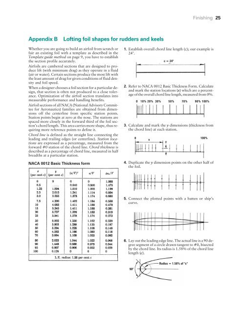
Appendix B Lofting foil shapes for rudders and keels<br />
Whether you are going to build an airfoil from scratch or<br />
fair an existing foil with a template as described in the<br />
Template guide method on page 9, you have to establish<br />
the section profile accurately.<br />
Airfoils are cambered sections that are designed to produce<br />
lift (with minimum drag) as they operate in a fluid<br />
(air or water). Certain sections produce the most lift with<br />
the least amount of drag for given conditions of fluid density<br />
and foil speed.<br />
When a designer chooses a foil section for a particular design,<br />
that section is often not produced to a close tolerance.<br />
Optimization of the airfoil section translates into<br />
measurable performance and handling benefits.<br />
Airfoil sections of all NACA (National Advisory Committee<br />
for Aeronautics) families are obtained from dimensions<br />
off the centerline from specific station points.<br />
Station points begin at zero at the nose. The stations are<br />
spaced more closely in the forward third of the foil section’s<br />
chord length. This area carries more shape, thus requiring<br />
more reference points to define it.<br />
Chord line is defined as the straight line connecting the<br />
leading and trailing edges (or centerline). Station locations<br />
are expressed as a percentage, measured from the<br />
forward #0 station of the chord line. Chord thickness is<br />
described as a percentage of chord line, measured in half<br />
breadths at a particular station.<br />
NACA 0012 Basic Thickness form<br />
<strong>Finishing</strong> 25<br />
1. Establish overall chord line length (c); our example is<br />
24".<br />
2. Refer to NACA 0012 Basic Thickness Form. Calculate<br />
and mark the station locations (x) which are a percentage<br />
of the overall chord line length, measured from 0%.<br />
3. Calculate and mark the y dimensions (thickness from<br />
the chord line) at each station.<br />
4. Duplicate the y dimension points on the other half of<br />
the foil.<br />
5. Connect the plotted points with a batten or ship’s<br />
curve.<br />
6. Lay out the leading edge line. The actual line is a 90 degree<br />
segment of a circle drawn tangent to #0, bisected<br />
by the chord line. Its radius is 1.58% of the chord line<br />
length (c).<br />
90°<br />
0<br />
0 10% 20% 30% 50% 70% 90% 100%<br />
x<br />
c = 24"<br />
y<br />
Radius = 1.58% of "c"<br />
100%