Final Fairing & Finishing - WEST SYSTEM Epoxy
Final Fairing & Finishing - WEST SYSTEM Epoxy
Final Fairing & Finishing - WEST SYSTEM Epoxy

You also want an ePaper? Increase the reach of your titles
YUMPU automatically turns print PDFs into web optimized ePapers that Google loves.
Root<br />
Midpoint<br />
Tip<br />
Waterline<br />
Plywood template<br />
<strong>Final</strong> <strong>Fairing</strong> 10<br />
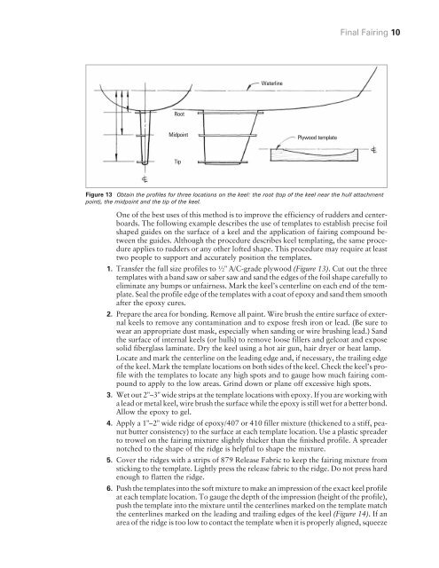
Figure 13 Obtain the profiles for three locations on the keel: the root (top of the keel near the hull attachment<br />
point), the midpoint and the tip of the keel.<br />
One of the best uses of this method is to improve the efficiency of rudders and centerboards.<br />
The following example describes the use of templates to establish precise foil<br />
shaped guides on the surface of a keel and the application of fairing compound between<br />
the guides. Although the procedure describes keel templating, the same procedure<br />
applies to rudders or any other lofted shape. This procedure may require at least<br />
two people to support and accurately position the templates.<br />
1. Transfer the full size profiles to ½" A/C-grade plywood (Figure 13). Cut out the three<br />
templates with a band saw or saber saw and sand the edges of the foil shape carefully to<br />
eliminate any bumps or unfairness. Mark the keel’s centerline on each end of the template.<br />
Seal the profile edge of the templates with a coat of epoxy and sand them smooth<br />
after the epoxy cures.<br />
2. Prepare the area for bonding. Remove all paint. Wire brush the entire surface of external<br />
keels to remove any contamination and to expose fresh iron or lead. (Be sure to<br />
wear an appropriate dust mask, especially when sanding or wire brushing lead.) Sand<br />
the surface of internal keels (or hulls) to remove loose fillers and gelcoat and expose<br />
solid fiberglass laminate. Dry the keel using a hot air gun, hair dryer or heat lamp.<br />
Locate and mark the centerline on the leading edge and, if necessary, the trailing edge<br />
of the keel. Mark the template locations on both sides of the keel. Check the keel’s profile<br />
with the templates to locate any high spots and to gauge how much fairing compound<br />
to apply to the low areas. Grind down or plane off excessive high spots.<br />
3. Wet out 2"–3" wide strips at the template locations with epoxy. If you are working with<br />
a lead or metal keel, wire brush the surface while the epoxy is still wet for a better bond.<br />
Allow the epoxy to gel.<br />
4. Apply a 1"–2" wide ridge of epoxy/407 or 410 filler mixture (thickened to a stiff, peanut<br />
butter consistency) to the surface at each template location. Use a plastic spreader<br />
to trowel on the fairing mixture slightly thicker than the finished profile. A spreader<br />
notched to the shape of the ridge is helpful to shape the mixture.<br />
5. Cover the ridges with a strips of 879 Release Fabric to keep the fairing mixture from<br />
sticking to the template. Lightly press the release fabric to the ridge. Do not press hard<br />
enough to flatten the ridge.<br />
6. Push the templates into the soft mixture to make an impression of the exact keel profile<br />
at each template location. To gauge the depth of the impression (height of the profile),<br />
push the template into the mixture until the centerlines marked on the template match<br />
the centerlines marked on the leading and trailing edges of the keel (Figure 14). Ifan<br />
area of the ridge is too low to contact the template when it is properly aligned, squeeze