

Switched-Capacitor Circuits - University of Toronto
Switched-Capacitor Circuits - University of Toronto
Switched-Capacitor Circuits - University of Toronto

You also want an ePaper? Increase the reach of your titles
YUMPU automatically turns print PDFs into web optimized ePapers that Google loves.
<strong>University</strong> <strong>of</strong> <strong>Toronto</strong><br />
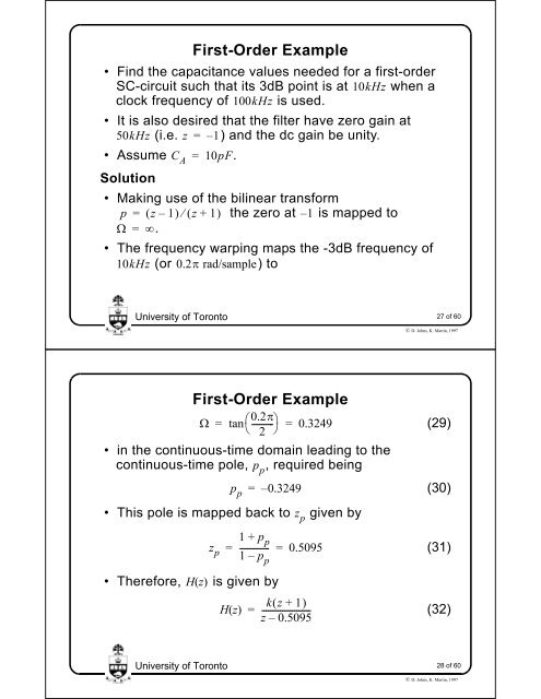
First-Order Example<br />
• Find the capacitance values needed for a first-order<br />
SC-circuit such that its 3dB point is at 10kHz when a<br />
clock frequency <strong>of</strong> 100kHz is used.<br />
• It is also desired that the filter have zero gain at<br />
50kHz (i.e. z = – 1)<br />
and the dc gain be unity.<br />
• Assume = 10pF.<br />
C A<br />
Solution<br />
• Making use <strong>of</strong> the bilinear transform<br />
p = z – 1<br />
z+ 1<br />
the zero at – 1 is mapped to<br />
= .<br />
• The frequency warping maps the -3dB frequency <strong>of</strong><br />
10kHz (or 0.2 rad/sample)<br />
to<br />
<strong>University</strong> <strong>of</strong> <strong>Toronto</strong><br />
First-Order Example<br />
=<br />
0.2<br />
tan---------- <br />
2 <br />
= 0.3249<br />
• in the continuous-time domain leading to the<br />
continuous-time pole, , required being<br />
p p<br />
• This pole is mapped back to given by<br />
p p<br />
– 0.3249<br />
zp =<br />
1 + pp --------------<br />
1 – pp = 0.5095<br />
• Therefore, Hz () is given by<br />
Hz ()<br />
=<br />
z p<br />
kz + 1<br />
=<br />
-----------------------z<br />
– 0.5095<br />
27 <strong>of</strong> 60<br />
© D. Johns, K. Martin, 1997<br />
(29)<br />
(30)<br />
(31)<br />
(32)<br />
28 <strong>of</strong> 60<br />
© D. Johns, K. Martin, 1997


