

Switched-Capacitor Circuits - University of Toronto
Switched-Capacitor Circuits - University of Toronto
Switched-Capacitor Circuits - University of Toronto

Create successful ePaper yourself
Turn your PDF publications into a flip-book with our unique Google optimized e-Paper software.
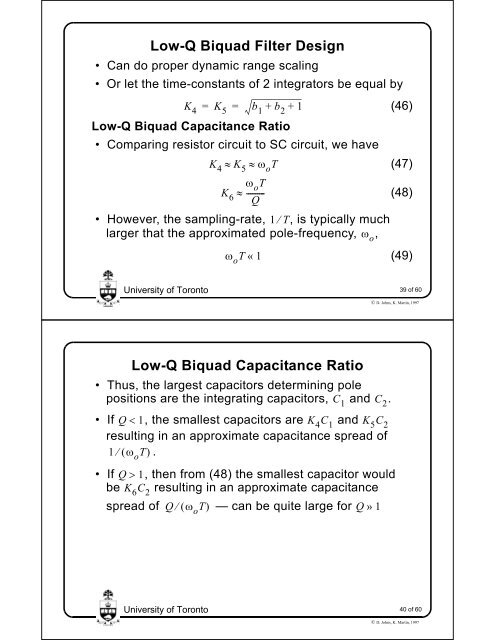
Low-Q Biquad Filter Design<br />
• Can do proper dynamic range scaling<br />
• Or let the time-constants <strong>of</strong> 2 integrators be equal by<br />
K4 = K5 = b1 + b2 + 1<br />
(46)<br />
Low-Q Biquad Capacitance Ratio<br />
• Comparing resistor circuit to SC circuit, we have<br />
K4 K5 oT (47)<br />
oT K6 ---------<br />
Q<br />
(48)<br />
• However, the sampling-rate, 1 T,<br />
is typically much<br />
larger that the approximated pole-frequency, ,<br />
<strong>University</strong> <strong>of</strong> <strong>Toronto</strong><br />
<strong>University</strong> <strong>of</strong> <strong>Toronto</strong><br />
oT « 1<br />
Low-Q Biquad Capacitance Ratio<br />
• Thus, the largest capacitors determining pole<br />
positions are the integrating capacitors, and .<br />
• If Q 1,<br />
the smallest capacitors are K4C1 and K5C2 resulting in an approximate capacitance spread <strong>of</strong><br />
1 oT. o<br />
(49)<br />
39 <strong>of</strong> 60<br />
© D. Johns, K. Martin, 1997<br />
• If Q 1,<br />
then from (48) the smallest capacitor would<br />
be K6C2 resulting in an approximate capacitance<br />
spread <strong>of</strong> Q oT — can be quite large for Q »<br />
1<br />
C 1<br />
C 2<br />
40 <strong>of</strong> 60<br />
© D. Johns, K. Martin, 1997


