

Cutler-Hammer - Eaton Canada
Cutler-Hammer - Eaton Canada
Cutler-Hammer - Eaton Canada

Create successful ePaper yourself
Turn your PDF publications into a flip-book with our unique Google optimized e-Paper software.
<strong>Cutler</strong>-<strong>Hammer</strong><br />
May 2001<br />
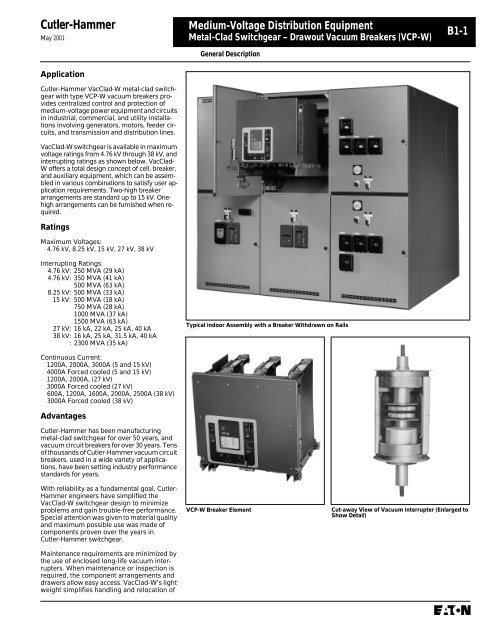
Application<br />
<strong>Cutler</strong>-<strong>Hammer</strong> VacClad-W metal-clad switchgear<br />
with type VCP-W vacuum breakers provides<br />
centralized control and protection of<br />
medium-voltage power equipment and circuits<br />
in industrial, commercial, and utility installations<br />
involving generators, motors, feeder circuits,<br />
and transmission and distribution lines.<br />
VacClad-W switchgear is available in maximum<br />
voltage ratings from 4.76 kV through 38 kV, and<br />
interrupting ratings as shown below. VacClad-<br />
W offers a total design concept of cell, breaker,<br />
and auxiliary equipment, which can be assembled<br />
in various combinations to satisfy user application<br />
requirements. Two-high breaker<br />
arrangements are standard up to 15 kV. Onehigh<br />
arrangements can be furnished when required.<br />
Ratings<br />
Maximum Voltages:<br />
4.76 kV, 8.25 kV, 15 kV, 27 kV, 38 kV<br />
Interrupting Ratings:<br />
4.76 kV: 250 MVA (29 kA)<br />
4.76 kV: 350 MVA (41 kA)<br />
500 MVA (63 kA)<br />
8.25 kV: 500 MVA (33 kA)<br />
15 kV: 500 MVA (18 kA)<br />
750 MVA (28 kA)<br />
1000 MVA (37 kA)<br />
1500 MVA (63 kA)<br />
27 kV: 16 kA, 22 kA, 25 kA, 40 kA<br />
38 kV: 16 kA, 25 kA, 31.5 kA, 40 kA<br />
: 2300 MVA (35 kA)<br />
Continuous Current:<br />
1200A, 2000A, 3000A (5 and 15 kV)<br />
4000A Forced cooled (5 and 15 kV)<br />
1200A, 2000A, (27 kV)<br />
3000A Forced cooled (27 kV)<br />
600A, 1200A, 1600A, 2000A, 2500A (38 kV)<br />
3000A Forced cooled (38 kV)<br />
Advantages<br />
<strong>Cutler</strong>-<strong>Hammer</strong> has been manufacturing<br />
metal-clad switchgear for over 50 years, and<br />
vacuum circuit breakers for over 30 years. Tens<br />
of thousands of <strong>Cutler</strong>-<strong>Hammer</strong> vacuum circuit<br />
breakers, used in a wide variety of applications,<br />
have been setting industry performance<br />
standards for years.<br />
With reliability as a fundamental goal, <strong>Cutler</strong>-<br />
<strong>Hammer</strong> engineers have simplified the<br />
VacClad-W switchgear design to minimize<br />
problems and gain trouble-free performance.<br />
Special attention was given to material quality<br />
and maximum possible use was made of<br />
components proven over the years in<br />
<strong>Cutler</strong>-<strong>Hammer</strong> switchgear.<br />
Maintenance requirements are minimized by<br />
the use of enclosed long-life vacuum interrupters.<br />
When maintenance or inspection is<br />
required, the component arrangements and<br />
drawers allow easy access. VacClad-W’s light<br />
weight simplifies handling and relocation of<br />
Medium-Voltage Distribution Equipment<br />
Metal-Clad Switchgear – Drawout Vacuum Breakers (VCP-W)<br />
General Description<br />
Typical Indoor Assembly with a Breaker Withdrawn on Rails<br />
VCP-W Breaker Element<br />
B1-1<br />
Cut-away View of Vacuum Interrupter (Enlarged to<br />
Show Detail)
B1-2<br />
Medium-Voltage Distribution Equipment<br />
Metal-Clad Switchgear – Drawout Vacuum Breakers (VCP-W)<br />
VacClad-W meets or exceeds all applicable<br />
ANSI, NEMA, and IEEE design standards, and<br />
additionally offers many outstanding safety<br />
features. To ensure reliability and quality, the<br />
testing of VacClad-W switchgears has been<br />
extensive. UL and CSA listed switchgear is<br />
also available.<br />
Features<br />
General Description<br />
Endurance<br />
High power laboratory tests prove VCP-W<br />
breakers are capable of 50 to 200 full fault<br />
current interruptions.<br />
Space Savings<br />
Up to 50% floor space reduction over previous<br />
designs.<br />
Vacuum Interrupter, Current Transfer<br />
Conductor<br />
The <strong>Cutler</strong>-<strong>Hammer</strong> stiff-flexible design eliminates<br />
sliding/rolling contacts in the main<br />
conductor which provides excellent electrical<br />
and thermal transfer and long vacuum interrupter<br />
life.<br />
Grounded Steel Safety Shutters<br />
Prevents accidental contact with live primary<br />
voltage connections when breaker is<br />
withdrawn.<br />
Breaker Rails<br />
On 5-27 kV units the breaker can be withdrawn<br />
on rails for inspection and maintenance without<br />
the need for a separate lifting device.<br />
Roll-on-the-Floor<br />
38 kV breaker is designed to roll directly on<br />
the floor.<br />
Reduced Breaker Weight<br />
525 Ibs. maximum through 27 kV vs. 2450 Ibs.<br />
in a comparable air-magnetic design for ease<br />
of handling.<br />
Reduced Breaker Maintenance<br />
Vacuum interrupter requires only periodic<br />
check for contact erosion. Integral wear<br />
indicator provided. No contact adjustments<br />
are required.<br />
Front Accessible Mechanism<br />
Front accessible mechanism is standard on<br />
all VCP-W breakers.<br />
Front Accessible CTs (5-27 kV)<br />
Up to 12 CTs per breaker can be mounted for<br />
easy access.<br />
Drawout Auxiliary Compartments<br />
Up to 4 drawers per vertical section can<br />
be equipped with CPTs or VTs up to 15 kV.<br />
Primary isolation shutters are standard.<br />
Fluidized Bed Epoxy Bus Insulation<br />
Excellent track resistant and flame retardant<br />
properties.<br />
Standardized Functional Designs<br />
Shortens order cycle time.<br />
Protective Relays<br />
A full scope of protective relays designed to<br />
meet all application requirements is available<br />
to provide the utmost in system and component<br />
protection, such the <strong>Cutler</strong>-<strong>Hammer</strong> Digitrip<br />
3000 / FP5000 relay. This microprocessorbased<br />
circuit protective, control and monitoring<br />
relay system includes devices 50, 51, 50N,<br />
51N, 50G, 51G and 86, plus cause and magnitude<br />
of trip, integral test and programming,<br />
ampere demand, high load alarm, non-volatile<br />
set-points, self-testing and communications<br />
capabilities. The Digitrip 3000 / FP5000 relay is<br />
capable of being monitored and controlled<br />
through the <strong>Cutler</strong>-<strong>Hammer</strong> IMPACC/Power-<br />
Net System and other monitoring/control<br />
packages. The Digitrip 3000 is further discussed<br />
elsewhere in this publication. Refer to<br />
section B2 for further information.<br />
IMPACC/PowerNet- Integrated Monitoring<br />
Protection and Control Communications<br />
System<br />
Medium-voltage VacClad-W switchgear is<br />
ideally suited for the unique <strong>Cutler</strong>-<strong>Hammer</strong><br />
IMPACC/PowerNet System.<br />
IMPACC/PowerNet is the unique system that,<br />
for the first time, ties together multiple devices<br />
in electrical distribution systems in a wide<br />
variety of buildings and plants.<br />
IMPACC/PowerNet utilizes the proven,<br />
INCOM chip for highly reliable, two-way<br />
communications (even in noisy industrial<br />
environments) between the master control<br />
unit and system devices via a twisted pair of<br />
conductors. Communications wires can be<br />
extended up to 10,000 feet from the master<br />
control unit without repeaters...and as many<br />
as 1,000 compatible devices, installed in<br />
various assemblies, can be on the IMPACC/<br />
PowerNet System.<br />
Easy Installation<br />
Installation is uncomplicated and devices are<br />
connected, daisy chain style, via the twisted<br />
pair conductors. All assemblies and devices<br />
are standard <strong>Cutler</strong>-<strong>Hammer</strong> equipment<br />
when IMPACC/PowerNet compatible devices<br />
are ordered as part of an assembly. The<br />
assemblies (with compatible devices built in)<br />
are prewired, pretested and delivered<br />
complete.<br />
Flexibility<br />
IMPACC/PowerNet is flexible in that it can<br />
include those assemblies, such as VacClad-W<br />
switchgear, that are desired in a distribution<br />
system...but IMPACC/PowerNet can be easily<br />
upgraded as new assemblies are added. In<br />
essence, a customer determines the requirements<br />
for a building’s electrical distribution<br />
system, and <strong>Cutler</strong>-<strong>Hammer</strong> provides the<br />
IMPACC/PowerNet System to fit those<br />
specific requirements.<br />
Refer to section B5 for more information on<br />
IMPACC/PowerNet.<br />
<strong>Cutler</strong>-<strong>Hammer</strong><br />
World Class VCP-W Vacuum Circuit Breakers<br />
Designed with a Patented V-Flex Nonsliding<br />
Current Transfer System<br />
Supplemental Devices<br />
May 2001<br />
Ground and Test Device<br />
The ground and test device is a drawout<br />
element that may be inserted into a metal-clad<br />
switchgear housing in place of a circuit breaker<br />
to provide access to the primary circuits to<br />
permit the temporary connection of grounds or<br />
testing equipment to the high-voltage circuits.<br />
High potential testing of cable or phase checking<br />
of circuits are typical tests which may be<br />
performed. The devices are insulated to suit the<br />
voltage rating of the switchgear and will carry<br />
required levels of short-circuit current.<br />
Before using ground and test devices it is<br />
recommended that each user develop detailed<br />
operating procedures consistent with safe operating<br />
practices. Only qualified personnel should<br />
be authorized to use ground and test devices.<br />
Manual and electrical ground and test devices<br />
are available. These devices include six studs<br />
for connection to primary circuits. On the manual<br />
device, selection and grounding is accomplished<br />
by cable connection. On electrical-type<br />
device, grounding is accomplished by electrically<br />
operated grounding switch.<br />
Standard Accessories:<br />
1 - test jumper<br />
1 - levering crank<br />
1 - maintenance tool<br />
1 - lifting yoke (5-27 kV)<br />
2 - set of rails (5-27 kV)<br />
1 - set of rail clamps (5-27 kV)<br />
1 - turning handle (5th wheel, 38 kV)<br />
Optional Accessories:<br />
1 - transport dolly (5-27 kV)<br />
1 - portable lifter (5-27 kV)<br />
1 - test cabinet<br />
1 - electrical levering device (5-27 kV)<br />
1 - ramp for lower breaker (5-27 kV)<br />
1 - manual or electrical ground and test device<br />
1 - hi-pot tester
<strong>Cutler</strong>-<strong>Hammer</strong><br />
May 2001<br />
26-inch Wide 5 kV 250 MVA 1200A Switchgear<br />
Application<br />
This new member of the VacClad-W MV Metal-<br />
Clad switchgear family was designed for use in<br />
instances where floor space requirements<br />
would not allow the industry standard 36-inch<br />
wide switchgear. Typical applications include<br />
not only new construction but also replacement<br />
switchgear for installations previously<br />
equipped with 26-inch wide airbreak devices.<br />
This new line of switchgear has also proven<br />
very popular among Generator Control<br />
manufacturers where 5 kV, 1200A, 250 MVA<br />
applications are commonplace.<br />
Ratings<br />
At the heart of the new switchgear line is<br />
the World-Class <strong>Cutler</strong>-<strong>Hammer</strong> VCPW-ND<br />
“Narrow Design” vacuum circuit breaker. The<br />
26-inch wide offering includes breakers and<br />
gear that are rated for use on 5 kV, 250 MVA,<br />
1200A, 60 kV BIL maximum systems. Main<br />
bus ratings of up to 3000A are available.<br />
38 kV Metal-Clad Switchgear<br />
Application<br />
This new member of the VacClad Switchgear<br />
family was designed for use in applications<br />
with distribution voltages at 38 kV maximum.<br />
Typical applications include not only new<br />
construction but also replacement for older<br />
airbreak, minimum oil or SF6 switchgear.<br />
This new line is available in two basic versions:<br />
one designed specifically for domestic<br />
and export ANSI applications (VacClad-W),<br />
with a continuous current range of 600-<br />
2000A; and one built for export only IEC<br />
applications (W-VAC) for continuous current<br />
ranges of 630-2000A.<br />
Ratings and Configurations<br />
Both ANSI and IEC versions offer 31.5 kA<br />
RMS SYM momentary short circuit, 80 kV<br />
1 minute withstand, 170 V BIL ratings as<br />
standard and both feature a revolutionary<br />
interface design that permits crossover and<br />
transition bus connections to adjacent sections<br />
without the need for a transition section.<br />
Standard dimensions of this 170 kV BIL<br />
gear is 42 inches wide x 100 inches tall x<br />
128.75 inches deep, making the VacClad-W<br />
offering the smallest in its class.<br />
Medium-Voltage Distribution Equipment<br />
Metal-Clad Switchgear – Drawout Vacuum Breakers (VCP-W)<br />
General Description<br />
Configurations<br />
Functionality is the name of the game.<br />
Available configurations include breaker over<br />
breaker, one or two auxiliaries over breaker,<br />
breaker over one or two auxiliaries or up to<br />
four auxiliaries in one vertical section.<br />
In addition to the tremendous floor space<br />
saving offered by the 26-inch wide design, a<br />
savings in the height of the switchgear is also<br />
available. Where height is an issue, such as<br />
an outdoor powerhouse or in a mobile power<br />
container, the standard 95-inch height can be<br />
reduced to an 80-inch tall model with a single<br />
high breaker with one auxiliary and/or<br />
control cubical. In addition, the low-profile<br />
structure is designed to accommodate Voltage<br />
Transformers which may be front or rear<br />
mounted. Shallow-depth versions are also<br />
available for applications where depth is an<br />
issue. Contact your local <strong>Cutler</strong>-<strong>Hammer</strong><br />
representative for more information on<br />
special dimensional requirements.<br />
Features and Benefits<br />
Safety has been thoroughly addressed in the<br />
design of the 38 kV VacClad-W. Both ANSI<br />
and IEC designs are designed and tested at<br />
the factory to be Corona-Free. In addition,<br />
optional Arc-Resistant designs can be<br />
specified to comply with EEMAC G-14-1 for<br />
Accessibility Types A, B and C. On all standard<br />
units, shutters can be independently<br />
padlocked to prevent inadvertent energizing<br />
during maintenance. Where needed, fully<br />
rated feeder and main bus earthing switches<br />
are also available.<br />
Ease of service is another benefit. All 38 kV<br />
switchgear units are equipped with roll-onthe-floor<br />
vacuum circuit breakers that provide<br />
both unprecedented mobility and ready<br />
accessibility to the breaker cell. Levering-in<br />
mechanisms for breaker installation employ<br />
an innovative ball-screw bearing drive that can<br />
be operated by a single technician. A motordriven<br />
levering system is also available.<br />
Like the <strong>Cutler</strong>-<strong>Hammer</strong> VacClad-W Metal-clad<br />
switchgear products, the 38 kV line can be<br />
equipped with a variety of optional features to<br />
enhance system protection and monitoring.<br />
The <strong>Cutler</strong>-<strong>Hammer</strong> Digitrip 3000 and FP5000<br />
microprocessor-based relays, IQ Analyzer and<br />
the IMPACC/PowerNet communications system<br />
are all available with the 38 kV metal-clad<br />
switchgear.<br />
B1-3<br />
For installations requiring 2000A main breakers<br />
with 1200A feeders, lineups can be built<br />
with standard 36-inch wide main breaker<br />
cubicals and 26-inch wide feeders. The main<br />
bus connections are 100% compatible with<br />
standard 36-inch wide vertical sections. As a<br />
result, add-ons to existing installations can be<br />
simply and rapidly performed without costly<br />
system modifications and transition sections.
B1-4<br />
Medium-Voltage Distribution Equipment<br />
Metal-Clad Switchgear – Drawout Vacuum Breakers (VCP-W)<br />
Table 1: Available VCP-W Vacuum Circuit Breaker Types Rated on Symmetrical Current Rating Basis, Per ANSI Standards➀<br />
Identification Rated Values Related Required Capabilities➁<br />
Circuit Nominal Nominal Voltage Insulation Level Current Rated Transient Rated Rated Rated Rated Current Values<br />
Breaker Voltage 3-Phase<br />
Recovery Voltage InterPermisReMaxi- Type Class MVA<br />
Class<br />
Rated<br />
Maximum<br />
Voltage<br />
Rated<br />
Voltage<br />
Range<br />
Factor<br />
Rated Withstand<br />
Test Voltage<br />
Rated<br />
Continuous<br />
Current<br />
Rated<br />
Short-<br />
Circuit<br />
Current<br />
Rated<br />
Crest<br />
Voltage<br />
Rated<br />
Time To<br />
Crest<br />
rupting<br />
Time<br />
sible<br />
Tripping<br />
Delay<br />
closing<br />
Time<br />
mum<br />
Voltage<br />
Divided<br />
By K<br />
Maximum<br />
Sym.<br />
Interrupting<br />
Capability<br />
3 Sec. Short-<br />
Time Current<br />
Carrying<br />
Capability<br />
at 60 Hz (at Rated<br />
Max. kV)<br />
K Times Rated<br />
50 VCP-<br />
WND<br />
250<br />
50 VCP-W<br />
250<br />
50 VCP-W<br />
350<br />
50 VCP-W<br />
500<br />
75 VCP-W<br />
500<br />
150 VCP-W<br />
500<br />
150 VCP-W<br />
750<br />
150 VCP-W<br />
1000<br />
150 VCP-W<br />
1500<br />
270 VCP-W<br />
750<br />
270 VCP-W<br />
1000<br />
270 VCP-W<br />
1250<br />
270 VCP-W<br />
40<br />
380 VCP-W<br />
16<br />
kV<br />
Class<br />
MVA<br />
Class<br />
V<br />
kV rms<br />
➂<br />
K<br />
Normal 1.2 x<br />
Fre- 50 µsec.<br />
quency Impulse<br />
➃<br />
➂<br />
I<br />
kA rms<br />
E2<br />
kV Crest T2<br />
➄<br />
Micro-sec Cycles<br />
Short-Circuit Current➂<br />
KI<br />
<strong>Cutler</strong>-<strong>Hammer</strong><br />
Closing and Latching<br />
Capability (Momentary) ➆<br />
2.7 K Times<br />
Rated<br />
Short-<br />
Circuit<br />
Current<br />
➅<br />
Y<br />
Sec. Cycles V/K<br />
kV rms kA rms kA rms kA Crest<br />
1.6 K Times<br />
Rated<br />
Short-<br />
Circuit<br />
Current<br />
➇<br />
kV rms kV Crest Amperes<br />
kA rms Assy.<br />
S<br />
4.16 250 4.76 1.24 19 60 1200 29 8.9 50 5 2 30 3.85 36 36 97 58 1.2<br />
4.16 250 4.76 1.24 19 60 1200<br />
2000<br />
3000<br />
4.16 350 4.76 1.19 19 60 1200<br />
2000<br />
3000<br />
4.16 500 4.76 1.0 19 60 1200<br />
2000<br />
3000<br />
7.2 500 8.25 1.25 36 95 1200<br />
2000<br />
3000<br />
13.8 500 15 1.30 36 95 1200<br />
2000<br />
3000<br />
13.8 750 15 1.30 36 95 1200<br />
2000<br />
3000<br />
13.8 1000 15 1.30 36 95 1200<br />
2000<br />
3000<br />
13.8 1500 15 1.0 36 95 1200<br />
2000<br />
3000<br />
27 — 27 1.0 60 125 600<br />
1200<br />
2000<br />
27 — 27 1.0 60 125 600<br />
1200<br />
2000<br />
27 — 27 1.0 60 125 600<br />
1200<br />
2000<br />
27 — 27 1.0 60 125 1200<br />
2000<br />
34.5 — 38 1.0 80 170<br />
➉<br />
380 VCP-W<br />
21<br />
34.5 — 38 1.65 80 170<br />
➉<br />
380 VCP-W<br />
25<br />
34.5 — 38 1.0 80 170<br />
➉<br />
380 VCP-W<br />
32<br />
380 VCP-W<br />
40<br />
Application and Technical Data<br />
34.5 — 38 1.0 80 170<br />
➉<br />
34.5 — 38 1.0 80 170<br />
➀<br />
➀ Contact <strong>Cutler</strong>-<strong>Hammer</strong> for capacitor switching,<br />
low inductive switching, and cable charging<br />
ratings.<br />
➁ For reclosing service, there is No De-Rating<br />
necessary for the <strong>Cutler</strong>-<strong>Hammer</strong> VCP-W family of<br />
circuit breakers. R = 100% . Type VCP-W breaker can<br />
perform the O-C-O per ANSI C37.09; O-0.3s-CO-15s-<br />
CO per IEC 56; and some VCP-Ws have performed<br />
O-0,3s-CO-15s-CO-15s-CO-15s-CO; all with no derating.<br />
Contact <strong>Cutler</strong>-<strong>Hammer</strong> for special reclosing<br />
requirements.<br />
➂ For 3-phase and line-to-line faults, the sym.<br />
interrupting capability at an operating voltage, Vo<br />
V<br />
=<br />
V<br />
(Rated Short-Circuit Current)<br />
o<br />
But not to exceed KI.<br />
600<br />
1200<br />
1600<br />
2000<br />
1200<br />
2000<br />
600<br />
1200<br />
1600<br />
2000<br />
600<br />
1200<br />
1600<br />
2000<br />
600<br />
1200<br />
1600<br />
2000<br />
2500<br />
29 8.9 50 5 2 30 3.85 36 36 97<br />
132➆<br />
41 8.9 50 5 2 30 4.0 49 49 132 78 1.2<br />
63 8.9 50 5 2 30 4.76 63 63 170 100.8 1.27<br />
33 15.5 60 5 2 30 6.6 41 41 111 66 1.2<br />
18 28 75 5 2 30 11.5 23 23 62<br />
97➆<br />
28 28 75 5 2 30 11.5 36 36 97<br />
130➆<br />
37 28 75 5 2 30 11.5 48 48 130 77 1.2<br />
63 28 75 5 2 30 15 63 63 170 100.8 1.27<br />
16 51 105 5 2 30 27 16 16 43 26 1.2<br />
22 51 105 5 2 30 27 22 22 60 35 1.2<br />
25 51 105 5 2 30 27 25 25 68 40 1.2<br />
40 51 105 5 2 30 27 40 40 108 64 1.2<br />
16 71 125 5 2 30 38 16 16 43 26 1.2<br />
21 71 125 5 2 30 23 35 35 95 56 1.2<br />
25 71 125 5 2 30 38 25 25 68 40 1.2<br />
31.5 71 125 5 2 30 38 31.5 31.5 85 51 1.2<br />
40 71 125 5 2 30 38 40 40 108 64 1.2<br />
Single line-to-ground fault capability at an<br />
operating voltage, V<br />
o<br />
V<br />
= 1.15 (Rated Short-Circuit Current)<br />
Vo<br />
But not to exceed KI.<br />
The above apply on predominately inductive or<br />
resistive 3-phase circuits with normal-frequency<br />
line-to-line recovery voltage equal to the operating<br />
voltage.<br />
➃ 4000A continuous rating is available for 5/15 kV.<br />
3000A continuous rating is available for 27/38 kV.<br />
Contact <strong>Cutler</strong>-<strong>Hammer</strong> for details.<br />
➄ 3-cycle rating available.<br />
➅ Tripping may be delayed beyond the rated<br />
permissible tripping delay at lower values of<br />
58<br />
78➆<br />
37<br />
58➆<br />
58<br />
77➆<br />
May 2001<br />
Asymmetry<br />
Factor for<br />
VCP-W<br />
Breakers<br />
current in accordance with the following formula:<br />
2<br />
(K Times Rated Short-Circuit Current)<br />
T (seconds) = Y[<br />
Short-Circuit Current Through Breaker ]<br />
The aggregate tripping delay on all operations<br />
within any 30-minute period must not exceed the<br />
time obtained from the above formula.<br />
➆ Non-standard breakers with high momentary<br />
rating available for special applications.<br />
➇ Included for reference only.<br />
➈ Asymmetrical interrupting capability = “S” times<br />
symmetrical interrupting capability, both at<br />
specified operating voltage.<br />
➉ ANSI standard requires 150 kV BIL. All 38 kV<br />
ratings are tested to 170 kV BIL.<br />
➈<br />
1.2<br />
1.2<br />
1.2
<strong>Cutler</strong>-<strong>Hammer</strong><br />
May 2001<br />
Application Quick Check<br />
See Table 2 for application of circuit breakers<br />
in a radial system supplied from a single<br />
source transformer. Short-circuit duty was<br />
determined using E/X amperes and 1.0<br />
multiplying factor for X/R ratios in the range<br />
of 15 to 40.<br />
Applications Above 3300 Feet [1000 m]<br />
The rated one-minute power frequency withstand<br />
voltage, the impulse withstand voltage,<br />
the continuous current rating and the maximum<br />
voltage rating must be multiplied by the<br />
appropriate correction factor in Table 3 to<br />
obtain modified ratings which most equal or<br />
exceed the application requirements. Note<br />
that intermediate values may be obtained<br />
by interpolation.<br />
Load Current Switching<br />
Table 4 showing number of operations is a<br />
guide to normal maintenance for circuit<br />
breakers operated under usual service conditions<br />
for most repetitive duty applications<br />
including isolated capacitor bank switching<br />
and shunt reactor switching, but not for arc<br />
furnace switching. The numbers in the table<br />
are equal to or in excess of those required by<br />
ANSI C37.06.<br />
Maintenance shall consist of adjusting, cleaning,<br />
lubricating, tightening, etc., as recommended<br />
by the circuit breaker instruction book.<br />
Continuous current switching assumes opening<br />
and closing rated continuous current at<br />
rated maximum voltage with power factor<br />
between 80% leading and 80% lagging.<br />
Inrush current switching assures a closing current<br />
equal to 600% of rated continuous current<br />
at rated maximum voltage with power factor<br />
of 30% lagging or less, and an opening current<br />
equal to rated continuous current at rated<br />
maximum voltage with power factor between<br />
80% leading and 80% lagging.<br />
In accordance with ANSI C37.06, if a<br />
short-circuit operation occurs before the<br />
completion of the listed switching operations,<br />
maintenance is recommended and possible<br />
functional part replacement may be necessary,<br />
depending on previous accumulated<br />
duty, fault magnitude and expected future<br />
operations.<br />
Applications Above or Below 40°C Ambient<br />
Refer to ANSI C37.20.2, section 7.4 for load<br />
current-carrying capabilities under various<br />
conditions of ambient temperature and load.<br />
➀ Also includes 50VCPW-ND250.<br />
➁ Transformer impedance 6.5% or more. All other<br />
transformer impedances are 5.5% or more.<br />
➂ Each operation is comprised of one closing plus<br />
one opening.<br />
Medium-Voltage Distribution Equipment<br />
Metal-Clad Switchgear – Drawout Vacuum Breakers (VCP-W)<br />
Table 2<br />
Source<br />
Transformer<br />
Operating Voltage<br />
MVA Rating kV<br />
Motor Load 2.4 4.16 6.6 12 13.8 27<br />
100% 0%<br />
Up to<br />
5<br />
7.5<br />
10➀<br />
Up to<br />
7.5<br />
10<br />
10<br />
10 12➁<br />
50 VCP-W<br />
250➀<br />
(36 kA)<br />
50 VCP-W<br />
350<br />
(49 kA)<br />
50 VCP-W<br />
250➀<br />
(33.2 kA)<br />
12 15 50 VCP-W<br />
350<br />
(46.9 kA)<br />
15<br />
20➁<br />
20<br />
25<br />
30<br />
50➁<br />
150 VCP-W<br />
500<br />
(23 kA)<br />
75 VCP-W<br />
500<br />
(41.3 kA)<br />
150 VCP-W<br />
500<br />
(22.5 kA)<br />
150 VCP-W<br />
750<br />
(35 kA)<br />
150 VCP-W<br />
1000<br />
(46.3 kA)<br />
150 VCP-W<br />
500<br />
(19.6 kA)<br />
150 VCP-W<br />
750<br />
(30.4 kA)<br />
150 VCP-W<br />
1000<br />
(40.2 kA)<br />
B1-5<br />
270 VCP-W<br />
750<br />
(16 kA)<br />
270 VCP-W<br />
1000<br />
(22 kA)<br />
25 50<br />
30 270 VCP-W<br />
1250<br />
(25 kA)<br />
Table 3<br />
Altitude Above<br />
Sea Level in<br />
Feet [m]<br />
3300 [1000]<br />
(and Below)<br />
4000 [1200]<br />
5000 [1500]<br />
6000 [1800]<br />
6600 [2000]<br />
7000 [2100]<br />
8000 [2400]<br />
9000 [2700]<br />
10000 [3000]<br />
12000 [3600]<br />
13200 [4000]<br />
14000 [4300]<br />
16000 [4900]<br />
16400 [5000]<br />
18000 [5500]<br />
20000 [6100]<br />
Table 4<br />
Application and Technical Data<br />
Altitude Correction<br />
Factor to be Applied to<br />
Voltage Rated<br />
Continuous<br />
Current<br />
1.0<br />
0.98<br />
0.95<br />
0.92<br />
0.91<br />
0.89<br />
0.86<br />
0.83<br />
0.80<br />
0.75<br />
0.72<br />
0.70<br />
0.65<br />
0.64<br />
0.61<br />
0.56<br />
1.0<br />
0.995<br />
0.99<br />
0.99<br />
0.985<br />
0.98<br />
0.97<br />
0.965<br />
0.96<br />
0.95<br />
0.94<br />
0.935<br />
0.925<br />
0.92<br />
0.91<br />
0.90<br />
Circuit Breaker Ratings Maximum Number of Operations➂<br />
Rated<br />
Maximum<br />
Voltage<br />
kV rms<br />
Breaker Type and<br />
Sym. Interrupting Capability<br />
at the Operating Voltage<br />
Rated<br />
Continuous<br />
Current<br />
Ampere<br />
Rated Short<br />
Circuit Current<br />
kA rms<br />
Between<br />
Servicing<br />
No-Load<br />
Mechanical<br />
Rated<br />
Continuous<br />
Current<br />
Switching<br />
Inrush<br />
Current<br />
Switching<br />
4.76, 8.25, 15 1200, 2000 33 kA and below 2000 10000 10000 750<br />
4.76, 8.25, 15 3000 All 1000 5000 5000 400<br />
4.76, 15 All 37 kA and above 1000 5000 5000 400<br />
27 All All 500 2500 2500 100<br />
38 All All 250 1500 1500 100
B1-6<br />
Surge Protection<br />
Medium-Voltage Distribution Equipment<br />
Metal-Clad Switchgear – Drawout Vacuum Breakers (VCP-W)<br />
Application and Technical Data<br />
VacClad-W metal-clad switchgear is applied<br />
over a broad range of circuits, and is one of<br />
the many types of equipment in the total system.<br />
The distribution system can be subject<br />
to voltage transients caused by lighting or<br />
switching surges.<br />
Recognizing this phenomenon, the industry<br />
has developed standards to provide guidelines<br />
for application of electrical equipment,<br />
which should be used in the design of distribution<br />
systems independent of the breaker<br />
interrupting medium. These standards are:<br />
ANSI C62 – Guides and Standards for Surge<br />
Protection<br />
IEEE 242 – Buff Book<br />
IEEE Recommended Practice for Protection<br />
and Coordination of Industrial and<br />
Commercial Power Systems<br />
IEEE 141 – Red Book<br />
Recommended Practice for Electric Power<br />
Distribution for Industrial Plants<br />
ANSI C37.20.2<br />
Metal-Clad Switchgear<br />
In general, if the BIL of the system is equal to<br />
the BIL of VacClad-W metal-clad switchgear, no<br />
protection is required against switching surges;<br />
however, standard BIL dry-type transformers<br />
and rotating apparatus rarely meet this criteria.<br />
For circuits exposed to lightning, protection is<br />
recommended in line with standard practices.<br />
In a wide range of applications, not all circuits<br />
require surge protection. Therefore, VacClad-W<br />
metal-clad switchgear does not include any<br />
surge protection as standard. The user exercises<br />
the options as to the type of protection<br />
deemed necessary, depending on the individual<br />
circuit characteristics and cost considerations.<br />
The following recommendations are outlined<br />
to provide guidelines of minimum surge<br />
protection for metal-clad switchgear and the<br />
associated system equipment:<br />
1. Lightning – Provide standard lightning<br />
protection.<br />
2. Switching surge protection:<br />
a. Liquid-filled transformer — no surge<br />
protection required.<br />
b. Dry-type transformers:<br />
38 kV - 170 kV BIL — no surge protection<br />
required.<br />
27 kV - 125 kV BIL — no surge protection<br />
required.<br />
15 kV - 95 kV BIL — no surge protection<br />
required.<br />
7.5 kV - 95 kV BIL — no surge protection<br />
required.<br />
5 kV - 60 kV BIL — no surge protection<br />
required.<br />
Turn-to-turn insulation protection:<br />
Surge capacitors may be required on<br />
some systems where a steep rate of<br />
rise is expected which may damage<br />
turn-to-turn insulation.<br />
For all other voltage/BIL ratings for<br />
dry-type transformers, surge protection<br />
(arresters or capacitors) is recommended<br />
at the transformer terminals,<br />
in line with established practices.<br />
Metal oxide surge arresters can be<br />
supplied in VacClad-W switchgear as<br />
an alternate to above.<br />
c. Motors — Surge capacitors at the<br />
motor terminals (and surge arresters<br />
where appropriate).<br />
d. Generators — Surge capacitors and<br />
station class surge arresters at<br />
machine terminals.<br />
e. Switching overhead lines and underground<br />
cables — No surge protection<br />
required.<br />
f. Capacitor switching — No surge<br />
protection required.<br />
g. Shunt reactor switching — Threephase<br />
15 kV dry-type reactors less<br />
than 9 MVA require surge protection<br />
at the reactor’s terminals.<br />
These application guidelines for VacClad-W<br />
metal-clad switchgear were established after<br />
extensive analysis of medium-voltage power<br />
systems.<br />
Surge Arresters<br />
The modern metal-oxide surge arresters are<br />
recommended because this latest advance in<br />
arrester design ensures better performance<br />
and high reliability of surge protection<br />
schemes. Manufacturer’s technical data must<br />
be consulted for correct application of a given<br />
type of arresters. Notice that published arrester<br />
MCOV (maximum continuous operating voltage)<br />
ratings are based on 40-45°C ambient<br />
temperature range. In general, the following<br />
guidelines are recommended for arrester<br />
selections, when installed inside the VCP-W<br />
metal-clad switchgear:<br />
a. Solidly Grounded System – Minimum<br />
arrester MCOV rating should be equal to<br />
1.05 x VLL/(1.732<br />
x T), where VLL<br />
is nominal<br />
line-to-line service voltage, 1.05 factor<br />
allows for +5% voltage variation above<br />
the nominal voltage according to ANSI<br />
C84.1, and T is derating factor to allow for<br />
operation at 55°C switchgear ambient,<br />
which should be obtained from the<br />
arrester manufacturer for the type of<br />
arrester under consideration. Typical<br />
values of T are: 0.946 to 1.0.<br />
b. Low Resistance Grounded Systems<br />
(systems grounded through resistor rated<br />
10 seconds) – Arrester 10-second MCOV<br />
capability at 60°C, which is obtained from<br />
manufacturer’s data, should be equal to<br />
1.05 VLL,<br />
where VLL<br />
is nominal line-to-line<br />
<strong>Cutler</strong>-<strong>Hammer</strong><br />
May 2001<br />
service voltage, and 1.05 factor allows for<br />
+5% voltage variation above the nominal<br />
voltage.<br />
c. Ungrounded Systems or Systems<br />
Grounded through impedance other than<br />
10-second resistor – The arrester minimum<br />
MCOV rating should be equal to 1.05 VLL/T,<br />
where VLL<br />
and T are as defined above.<br />
Surge Capacitors<br />
Metal-oxide surge arresters limit the magnitude<br />
of prospective surge overvoltage, but<br />
are ineffective in controlling its rate of rise.<br />
Specially designed capacitors with low internal<br />
inductance are used to limit the rate of<br />
rise of this surge overvoltage to protect<br />
turn-to-turn insulation. Recommended values<br />
for surge capacitors are: 0.5 µf on 5 kV<br />
and 7.5 kV, 0.25 µf on 15 kV, and 0.13 µf on 24<br />
kV and higher systems.<br />
Arc Furnace Transformer Protection<br />
For arc furnace transformer protection, recommended<br />
RC network and arresters are shown<br />
below. For values of Cs<br />
and Rs,<br />
see Table 5. The<br />
resistor is important to limit capacitive current<br />
in the event of a re-ignition. This is especially<br />
important when large power-factor correction<br />
capacitor banks are used.<br />
Transformer<br />
Arc Furnace<br />
Main Bus<br />
VCP-W<br />
Vacuum Circuit Breaker<br />
R S<br />
C S<br />
Surge<br />
Arrester<br />
Resistor-Capacitor Protection for Arc Furnace<br />
Instrument Transformers<br />
Instrument transformers are used to protect<br />
personnel and secondary devices from high<br />
voltage and permit use of reasonable insulation<br />
levels for relays, meters and instruments.<br />
The secondaries of standard instrument<br />
transformers are rated at 5 amperes and/or<br />
120 volts, 60 Hertz.<br />
Voltage Transformers<br />
Selection of the ratio for voltage transformers<br />
is seldom a question since the primary rating<br />
should be equal to or higher than the system<br />
line-to-line voltage. The number of potential<br />
transformers per set and their connection is<br />
determined by the type of system and the<br />
relaying and metering required.
<strong>Cutler</strong>-<strong>Hammer</strong><br />
May 2001<br />
The 3-phase, 3-wire system with 2-element<br />
watt-hour meters would require a set of<br />
two line-to-line voltage transformers. If<br />
line-to-ground potential is also required for<br />
a directional ground relay, then a set of three<br />
line-to-ground voltage transformers could<br />
be used to provide both line-to-line potential<br />
for the 2-element watt-hour meter and<br />
line-to-ground potential for the ground relay.<br />
Ground detection lights or relays for the<br />
ungrounded system requires three line-toground<br />
voltage transformers and a separate<br />
set is usually recommended for this purpose.<br />
The 3-phase, 4-wire, solidly grounded system<br />
usually requires three line-to-ground voltage<br />
transformers for 2 1 /2- or 3-element metering.<br />
Where synchronizing of generators or<br />
systems is involved, it is recommended that<br />
only line-to-line potential be used.<br />
Current Transformers<br />
The current transformer ratio is generally<br />
selected so that the maximum load current<br />
will read about 70 percent full scale on a standard<br />
5-ampere coil ammeter. Therefore, the<br />
current transformer primary rating should be<br />
140 to 150 percent of the maximum load current.<br />
Maximum system fault current can sometimes<br />
influence the current transformer ratio<br />
selection since the connected secondary<br />
devices have published one-second ratings.<br />
The zero-sequence current transformer is<br />
used for sensitive ground fault relaying or<br />
self-balancing primary current type machine<br />
differential protection. The zero-sequence<br />
current transformer is available with a<br />
nominal ratio of 50/5 or 100/5 and available<br />
opening size for power cables of 7.25 inches,<br />
special zero-sequence transformers with<br />
larger windows are also available.<br />
The minimum number of current transformers<br />
for circuit relaying and instruments is<br />
three current transformers, one for each<br />
phase or two-phase connected current<br />
transformers and one zero-sequence current<br />
transformer. Separate sets of current transformers<br />
are required for differential relays.<br />
The minimum pickup of a ground relay in the<br />
residual of three-phase connected current<br />
transformers is primarily determined by the<br />
current transformer ratio. The relay pickup can<br />
be reduced by adding one residual connected<br />
auxiliary current transformer. This connection<br />
is very desirable on main incoming and tie<br />
circuits of low resistance grounded circuits.<br />
Standard accuracy current transformers are<br />
normally more than adequate for most standard<br />
applications of microprocessor-based<br />
➀ Cable surge impedance 37Ω.<br />
➁ For solidly grounded 4160 volt system only or<br />
any type 2400 volt system.<br />
Medium-Voltage Distribution Equipment<br />
Metal-Clad Switchgear – Drawout Vacuum Breakers (VCP-W)<br />
Table 6: Standard Voltage Transformer, 60 Hertz<br />
LL = Line-to-line connection.<br />
LG = Line-to-ground connection.<br />
B1-7<br />
Rating-<br />
Volts<br />
2400 4200 4800 7200 8400 10800 12000 14400 15600 18000 21000 24000 27000 36000<br />
Ratio 20-1 35-1 40-1 60-1 70-1 90-1 100-1 120-1 130-1 150-1 175-1 200-1 225-1 300-1<br />
Switchgear Voltage Transformer – ANSI Accuracy<br />
kV<br />
Class<br />
kV<br />
BIL<br />
Maximum<br />
Number<br />
Per Set and<br />
Connection<br />
5 60 2LL<br />
or 3LG<br />
7.5<br />
and<br />
15<br />
Application and Technical Data<br />
Table 5: Characteristics of Transformers for Arc Furnaces and Protection<br />
Arc Furnace Transformer R-C Protection<br />
Voltage<br />
kV<br />
MVA Continuous<br />
Current<br />
Short<br />
Circuit<br />
Magnetizing<br />
Current<br />
Cap.<br />
Cs RES. Rs Ohm<br />
50 Ft. Cable➀ 100 Ft. Cable➀ 1000 Ft. Cable➀<br />
A<br />
Z% % A Microf. ohm watt ohm watt ohm watt<br />
25.5 50 1130 2.4 0.155 1.75 0.018 15.47 0.15 21.87 0.21 69.16 0.66<br />
23 35 878 3.5 0.16 1.4 0.016 16.41 0.10 23.21 0.14 73.39 0.45<br />
13.2 30 1312 3 0.796 10.4 0.204 4.56 1.54 6.45 2.18 20.40 6.90<br />
13.2 50 2000 2.4 0.765 15.30 0.326 3.60 3.13 5.10 4.43 16.12 14.00<br />
95 2LL<br />
or 3LG<br />
27 125 2LL<br />
or 3LG<br />
38 170 2LL<br />
or 3LG<br />
Standard<br />
Ratio’s<br />
20,➁<br />
35,<br />
40<br />
35, 40,<br />
60, 70,<br />
100, 120<br />
90, 100,<br />
120, 130,<br />
150, 175,<br />
200, 225<br />
Table 7: Current Transformers, 55°C Ambient<br />
CT Ratio<br />
(MR= Multi-Ratio)<br />
50:5<br />
75:5<br />
100:5<br />
150:5<br />
200:5<br />
250:5<br />
300:5<br />
400:5<br />
500:5<br />
600:5<br />
800:5<br />
1000:5<br />
1200:5<br />
1500:5<br />
2000:5<br />
2500:5<br />
3000:5<br />
4000:5<br />
600:5 MR<br />
1200:5 MR<br />
2000:5 MR<br />
3000:5 MR<br />
50:5 Zero Seq<br />
100:5 Zero Seq<br />
Burdens at 120 Volts Burdens at 69.3 Volts Thermal<br />
W, X, Y Z M ZZ W, X Y M Z<br />
Rating<br />
55°C<br />
Conn.<br />
0.3 1.2 0.3 LL<br />
LG<br />
LG➂<br />
0.3 0.3 0.3 0.6 0.3 0.3 0.3 1.2 LL<br />
LG<br />
LG➂<br />
0.3 0.3 0.3 1.2 0.3 0.3 0.3 1.2 LL<br />
LG<br />
LG➂<br />
175, 300 0.3 0.3 0.3 0.3 0.3 0.3 0.3 0.3 LL<br />
LG<br />
LG➂<br />
Metering Accuracy Classification Relaying Accuracy Classification<br />
at 60 Hz<br />
Standard<br />
Burden<br />
B 0.1<br />
1.2<br />
1.2<br />
1.2<br />
0.6<br />
0.6<br />
0.6<br />
0.6<br />
0.3<br />
0.3<br />
0.3<br />
0.3<br />
0.3<br />
0.3<br />
0.3<br />
0.3<br />
0.3<br />
0.3<br />
0.3<br />
0.3<br />
0.3<br />
0.3<br />
0.3<br />
at 60 Hz<br />
Standard<br />
Burden<br />
B 0.5<br />
2.4<br />
2.4<br />
2.4<br />
2.4<br />
2.4<br />
2.4<br />
1.2<br />
0.3<br />
0.3<br />
0.3<br />
0.3<br />
0.3<br />
0.3<br />
0.3<br />
0.3<br />
0.3<br />
0.3<br />
0.3<br />
0.3<br />
0.3<br />
0.3<br />
➂ For solidly grounded system only.<br />
➃ Not listed in C37.20.2.<br />
at 60 Hz<br />
Standard<br />
Burden<br />
B 1.8<br />
2.4<br />
2.4<br />
2.4<br />
2.4<br />
1.2<br />
0.3<br />
0.3<br />
0.3<br />
0.3<br />
0.3<br />
0.3<br />
0.3<br />
2.4<br />
0.3<br />
0.3<br />
0.3<br />
Minimum<br />
Accuracy<br />
Required<br />
per IEEE<br />
C37.20.2<br />
C10<br />
C10<br />
C10<br />
C20<br />
C20<br />
C20<br />
C20<br />
C50 ➃<br />
C50<br />
C100 ➃<br />
C100<br />
C100<br />
C100 ➃<br />
C100<br />
C100 ➃➃➃➃<br />
Standard<br />
Accuracy<br />
Supplied in<br />
VCP-W<br />
Switchgear<br />
C10<br />
C20<br />
C20<br />
C20<br />
C20<br />
C20<br />
C50<br />
C50<br />
C50<br />
C100<br />
C100<br />
C100<br />
C200<br />
C200<br />
C200<br />
C200<br />
C200<br />
C200<br />
C100<br />
C200<br />
C200<br />
C200<br />
C20<br />
C20<br />
Voltamp<br />
700<br />
400<br />
700<br />
1000<br />
550<br />
1000<br />
1000<br />
550<br />
1000<br />
1000<br />
550<br />
1000<br />
Optional<br />
High<br />
Accuracy<br />
Available in<br />
VCP-W<br />
Switchgear<br />
—<br />
—<br />
—<br />
C50<br />
C50<br />
C50<br />
C100<br />
C100<br />
C100<br />
C200<br />
C200<br />
C200<br />
C400<br />
C400<br />
C400<br />
C400<br />
C400<br />
C400<br />
C200<br />
C400<br />
C400<br />
C400
B1-8<br />
Medium-Voltage Distribution Equipment<br />
Metal-Clad Switchgear – Drawout Vacuum Breakers (VCP-W)<br />
Application and Technical Data<br />
Control Equipment<br />
Circuit Breaker Control<br />
The VCP-W circuit breaker has a motor charged<br />
spring type stored energy closing mechanism.<br />
Closing the breaker charges accelerating<br />
springs. Protective relays or the control switch<br />
will energize a shunt trip coil to release the<br />
accelerating springs and open the breaker. This<br />
requires a reliable source of control power for<br />
the breaker to function as a protective device.<br />
For ac control, a capacitor trip device is used<br />
with each circuit breaker shunt trip to ensure<br />
that energy will be available for tripping during<br />
fault conditions. A control power transformer<br />
is required on the source side of each<br />
incoming line breaker. Closing bus tie or bus<br />
sectionalizing breakers will require automatic<br />
transfer of control power. This control power<br />
transformer may also supply other ac auxiliary<br />
power requirements for the switchgear.<br />
Signal: Initiation of<br />
Initiation of<br />
Close Signal<br />
Trip Signal<br />
VCP-W<br />
Circuit Breaker<br />
Main Contacts<br />
Breaker Aux.<br />
Switch<br />
"a" Contact<br />
Rated<br />
Control<br />
Voltage<br />
48 Vdc<br />
125 Vdc<br />
250 Vdc<br />
120 Vac<br />
240 Vac<br />
9.0<br />
4.0<br />
2.0<br />
4.0<br />
2.0<br />
C<br />
Closing Time<br />
∆t = 45-60 ms<br />
6<br />
6<br />
6<br />
6<br />
6<br />
∆t ±3 ms<br />
16<br />
7<br />
4<br />
6<br />
3<br />
200<br />
80<br />
40<br />
T<br />
Opening Time<br />
∆t = 30-45 ms<br />
Table 11: Control Power Transformers, 1 Phase, 60 Hertz➀➁<br />
Taps Secondary<br />
+7<br />
Volts<br />
1 ⁄2% Rated -71 ⁄2%<br />
2580<br />
2400<br />
2220<br />
240/120<br />
4470<br />
4160<br />
3850<br />
240/120<br />
5160<br />
4800<br />
4400<br />
240/120<br />
7740<br />
7200<br />
6680<br />
240/120<br />
9030<br />
8400<br />
7770<br />
240/120<br />
13405<br />
12470<br />
11535<br />
240/120<br />
14190<br />
13200<br />
12210<br />
240/120<br />
14835<br />
13800<br />
12765<br />
240/120<br />
24725<br />
23000<br />
21275<br />
240/120<br />
37088<br />
34500<br />
31913<br />
240/120<br />
38-56<br />
100-140<br />
200-280<br />
104-127<br />
208-254<br />
<strong>Cutler</strong>-<strong>Hammer</strong><br />
∆t ±3 ms<br />
28-56<br />
70-140<br />
140-280<br />
104-127<br />
208-254<br />
kVA kV<br />
Class<br />
5, 10, 15<br />
5, 10, 15<br />
5, 10, 15<br />
5, 10, 15<br />
5, 10, 15<br />
5, 10, 15<br />
5, 10, 15<br />
5, 10, 15<br />
5, 10, 15<br />
15, 25<br />
5<br />
5<br />
5<br />
15<br />
15<br />
15<br />
15<br />
15<br />
27<br />
38➂<br />
.035<br />
.035<br />
.035<br />
.035<br />
.035<br />
May 2001<br />
Dc control would require a dc control battery,<br />
Open<br />
battery charger and an ac auxiliary power<br />
source for the battery charger. The battery provides<br />
a very reliable dc control source, since it<br />
is isolated from the ac power system by the<br />
battery charger. However, the battery will require<br />
periodic routine maintenance and battery<br />
capacity is reduced by low ambient temperature.<br />
Breaker Aux.<br />
Switch<br />
"b" Contact<br />
"b" Breaks 6 ms<br />
Before "a" Makes<br />
∆t –6 ms<br />
to –3 ms<br />
"a" Breaks 7 ms<br />
Before "b" Makes<br />
Closed<br />
∆t +10 ms<br />
to +4 ms Open<br />
Any economic comparison of ac and dc con-<br />
Table 9: Auxiliary Switch Contacts Interrupting Capacities<br />
trol for switchgear should consider that the ac Type Auxiliary Switch Continuous Control Circuit Voltage<br />
capacitor trip is a static device with negligible<br />
maintenance and long life, while the dc bat-<br />
Current<br />
Amperes<br />
120 Ac 240 Ac 48 Dc 125 Dc 250 Dc<br />
tery will require maintenance and replace-<br />
Non-inductive circuit interrupting capacity in amperes<br />
ment at some time in the future.<br />
Breaker Auxiliary Switch 20<br />
15<br />
10<br />
16<br />
10<br />
5<br />
TOC<br />
20<br />
15<br />
10<br />
16<br />
10<br />
5<br />
Relays<br />
MOC Auxiliary Switch 20<br />
15<br />
10<br />
16<br />
10<br />
5<br />
Microprocessor-based or solid-state relays<br />
Inductive circuit interrupting capacity in amperes<br />
would generally require dc power or reliable<br />
uninterruptible ac supply for their logic circuits.<br />
Breaker Auxiliary Switch<br />
TOC<br />
20<br />
20<br />
15<br />
15<br />
10<br />
10<br />
16<br />
16<br />
10<br />
10<br />
5<br />
5<br />
Auxiliary Switches<br />
MOC Auxiliary Switch 20<br />
15<br />
10<br />
16<br />
10<br />
5<br />
Optional circuit breaker and cell auxiliary<br />
switches are available where needed for<br />
interlocking or control of auxiliary devices.<br />
Typical applications and operation are<br />
described in Tables 8 and 9.<br />
Table 10: VCP-W Breaker Stored Energy Mechanism Control Power Requirements<br />
Spring Charge Motor UV Trip Voltage Range Ind.<br />
Run Time Close or Trip<br />
mA (Max.)<br />
Close Trip<br />
Light<br />
Amperes Seconds Amperes<br />
Amperes<br />
Auxiliary switch contacts from the circuit<br />
breaker mechanism are limited in number by<br />
the breaker control requirements usually to<br />
one “a” and two “b” contacts for ac control or<br />
two “a” and two “b” contacts for dc control.<br />
When additional auxiliary contacts are needed,<br />
the optional auxiliary relay or mechanism<br />
operated cell (MOC) switch is used. Two<br />
types of MOC switches are available:<br />
a. operates with breaker in connected<br />
position only.<br />
b. operates with breaker in connected<br />
➀ Line-to-line connection only available.<br />
➁ Refer to <strong>Cutler</strong>-<strong>Hammer</strong> for other voltages and<br />
kVA ratings.<br />
➂ 150 kV BIL.<br />
position and test position.<br />
The optional truck operated cell (TOC) switch<br />
operates when the circuit breaker is levered<br />
into or out of the operating position.<br />
MOC and TOC switch contacts are not field<br />
convertible from “a” to “b” or “b” to “a”. Up<br />
to 3 MOC switches, each with 5a and 4b contacts,<br />
and 1 TOC with 4a and 5b contacts can<br />
Table 8: Breaker Auxiliary Switch Operating Times<br />
be provided in each breaker compartment.<br />
Auxiliary switch contacts are primarily used<br />
to provide interlocking in control circuits,<br />
switch indicating lights, auxiliary relays or<br />
other small loads. Suitability for switching<br />
remote auxiliary devices, such as motor heaters<br />
or solenoids, may be checked with the<br />
interrupting capacity listed in Table 9. Where<br />
higher interrupting capacities are required,<br />
Closed<br />
Open<br />
Closed
<strong>Cutler</strong>-<strong>Hammer</strong><br />
May 2001<br />
3<br />
1<br />
50/5<br />
BUS<br />
52<br />
A<br />
Digitrip 3000<br />
or FP5000<br />
50/51<br />
50/51N<br />
50/51G<br />
A<br />
Ct Rating = 200% Feeder Full Load<br />
Digitrip 3000 or FP5000 Multifunction Microprocessor Overcurrent Trip Unit<br />
A – Alternate to 50/51N<br />
Protective Relays – Feeder Circuit<br />
2<br />
27/<br />
47<br />
27/<br />
47X<br />
1<br />
1<br />
1<br />
50/5<br />
Protective Relays – Induction Motors Below 1500 Hp<br />
Minimum Adequate Protection➀<br />
3<br />
BUS<br />
52<br />
M<br />
Phase Ct Rating = 150% Full Load<br />
MP-3000 Multifunction Motor Protection Unit<br />
27/47 – Undervoltage, Phase Sequence, and Unbalanced Voltage Relay<br />
(One Per Bus)<br />
27/47x – Auxiliary Relay for Multimotor System<br />
➀ For additional backup overcurrent/short circuit protection a<br />
Digitrip 3000 or FP500 Relay can be added in addition to the MP-3000.<br />
1<br />
Medium-Voltage Distribution Equipment<br />
Metal-Clad Switchgear – Drawout Vacuum Breakers (VCP-W)<br />
MP-3000<br />
49<br />
50<br />
51<br />
46<br />
86<br />
51G<br />
Relays – Device Numbers, Type and Function<br />
For AC Generator, Transformer and AC Motor Protection Industrial and Commercial Power System Applications<br />
➀<br />
3<br />
3<br />
1<br />
50/5<br />
3<br />
BUS<br />
52<br />
Protective Relays – Transformer Feeder<br />
A<br />
Digitrip 3000<br />
or FP5000<br />
1<br />
50/51<br />
50/51N<br />
86<br />
50/51G<br />
A<br />
1<br />
63<br />
Protective Relays – Induction Motors Above 1500 Hp<br />
and Synchronous Motors➀<br />
3<br />
86 87T<br />
Phase Ct Rating = 150% Full Load<br />
A - Prefered Scheme<br />
B - Alternate Scheme<br />
IQ-1000-II – Multifunction Motor Protection Unit<br />
87 - Motor Differential Relay<br />
86 - Lockout Relay<br />
27/47 – Undervoltage, Phase Sequence, and Unbalanced Voltage Relay<br />
(One Per Bus)<br />
27/47x – Auxiliary Relay for Multi-motor System<br />
55 – Loss of Synchronism (Synchronous Motors Only)<br />
URTD – Universal RTD Interface Module<br />
B1-9<br />
Ct Rating = 200% Full Load<br />
Digitrip 3000 or FP5000 Multifunction Microprocessor Overcurrent Trip Unit<br />
87T – Transformer Differential Relay (Above 5 MVA)<br />
86 – Lockout Relay<br />
63 – Sudden Pressure Relay (Liquid Above 5 MVA)<br />
A – Alternate to 50/51N<br />
2<br />
27/47<br />
27/<br />
47X<br />
1<br />
1<br />
3<br />
3<br />
1<br />
50/5<br />
NEUT 3<br />
➁ Optional for MP-5000.<br />
3<br />
52<br />
M<br />
BUS<br />
A<br />
B<br />
MP-3000/MP-5000<br />
49<br />
50<br />
51<br />
46<br />
37<br />
38<br />
66<br />
2/19<br />
➀<br />
74<br />
50G<br />
51G<br />
86<br />
3 ➁<br />
87 86<br />
87 86<br />
A<br />
B<br />
RTD<br />
U<br />
R<br />
T<br />
D<br />
55
B1-10<br />
Medium-Voltage Distribution Equipment<br />
Metal-Clad Switchgear – Drawout Vacuum Breakers (VCP-W)<br />
Typical Units Available Configurations<br />
Terminal<br />
Blocks<br />
36-inch [914.4] Wide Typical Breaker/Breaker<br />
Vertical Section<br />
1 - 1200/2000/3000-ampere main bus.<br />
2 - Type VCP-W breakers 1200/2000-ampere<br />
in 2-high configuration.<br />
4 - Current transformers per phase,<br />
standard accuracy.<br />
- Surge arresters, if desired.<br />
- Zero sequence current transformer (ZST).<br />
Terminal<br />
Blocks<br />
Layout Dimensions➀ – 5 and 15 kV<br />
QC<br />
Bkr.<br />
Breaker<br />
CTS<br />
Breaker<br />
PT<br />
CPT<br />
CTS<br />
Breaker<br />
CTS<br />
36-inch [914.4] Wide Typical Auxiliary/Breaker<br />
Vertical Section<br />
1 - 1200/2000/3000-ampere main bus.<br />
1 - Type VCP-W breaker 1200/2000-ampere in<br />
lower position.<br />
1 - Drawout voltage transformer drawer.<br />
2 -L-L with fuses.<br />
3 -L-G with fuses.<br />
1 - Drawout control power transformer<br />
drawer CPT - 15 kVA max. - single phase.<br />
- Surge arresters, if desired.<br />
[ ] = Dimensions in mm.<br />
H<br />
96.25<br />
[2444.75]<br />
H<br />
96.25<br />
[2444.75]<br />
➀ For 4000A force cooled application, refer to<br />
<strong>Cutler</strong>-<strong>Hammer</strong>.<br />
➁ Breakers cannot be located in bus transition<br />
compartment.<br />
➂ Breakers can be located in these compartments.<br />
Main Bus<br />
Gnd.<br />
Bus<br />
Main Bus<br />
Gnd. Bus<br />
ARR<br />
ARR<br />
ARR<br />
ARR<br />
Zero<br />
Seq.<br />
CT<br />
Zero<br />
Seq.<br />
CT<br />
Z (1)<br />
H<br />
Z (1)<br />
H<br />
H<br />
H<br />
95.00<br />
[2413]<br />
95.00<br />
[2413]<br />
36-inch [914.4] Wide Typical Auxiliary/Auxiliary<br />
Vertical Section<br />
1 - 1200/2000/3000-ampere main bus.<br />
Illustrating maximum utilization of<br />
auxiliary compartment with 4-high<br />
draw-out auxiliaries and fixed mounted<br />
control power transformer.<br />
Tie<br />
Bus<br />
Transition➁<br />
52 52<br />
➂ ➂<br />
Bus<br />
Transition➁<br />
Drawout CPT<br />
QC<br />
Bkr.<br />
Drawout<br />
V.T.’s<br />
Drawout<br />
V.T.’s<br />
Drawout<br />
Fuses<br />
Tie<br />
52 52<br />
➂ ➂<br />
96.25<br />
[2444.75]<br />
➂ ➂<br />
52<br />
Tie<br />
52<br />
Bus<br />
Transition➁<br />
52<br />
Bus<br />
Transition➁<br />
➂ ➂<br />
Dimensions for Estimating Purposes Only.<br />
Main Bus<br />
Gnd.<br />
Bus<br />
Fixed CPT<br />
Tie Breaker Bus Transition<br />
Requirements<br />
52<br />
Tie<br />
95.00<br />
[2413]<br />
1200-Amp<br />
Breaker<br />
1200-Amp<br />
Breaker<br />
Drawout<br />
Auxiliary<br />
1200-Amp<br />
Breaker<br />
Vented<br />
Auxiliary<br />
Compartment<br />
(Non-<br />
Draw-out)<br />
3000-Amp<br />
Breaker<br />
➀<br />
3000-Amp<br />
Breaker<br />
Vent Area<br />
Drawout<br />
Auxiliary<br />
<strong>Cutler</strong>-<strong>Hammer</strong><br />
1200-Amp<br />
Breaker<br />
2000-Amp<br />
Breaker<br />
2000-Amp<br />
Breaker<br />
Drawout<br />
Auxiliary<br />
Drawout<br />
Auxiliary<br />
Draw-out<br />
Auxiliary<br />
May 2001<br />
1200-Amp<br />
Breaker<br />
Drawout<br />
Auxiliary<br />
Drawout<br />
Auxiliary<br />
2000-Amp<br />
Breaker<br />
2000-Amp<br />
Breaker<br />
1200-Amp<br />
Breaker
<strong>Cutler</strong>-<strong>Hammer</strong><br />
May 2001<br />
Typical Weights, Lbs. (kg)<br />
Assemblies (Less Breakers)<br />
Type of<br />
Vertical<br />
Section<br />
Main Bus<br />
Rating<br />
Amperes<br />
B/B 1200<br />
2000<br />
3000<br />
B/A<br />
or<br />
A/B<br />
1200<br />
2000<br />
3000<br />
A/A 1200<br />
2000<br />
3000<br />
B 1200<br />
2000<br />
3000<br />
Breakers Weights<br />
Type of<br />
Breaker<br />
50 VCP-W 250<br />
50 VCP-W 350<br />
50 VCP-W 500<br />
75 VCP-W 500<br />
150 VCP-W 500<br />
150 VCP-W 750<br />
150 VCP-W 1000<br />
150 VCP-W 1500<br />
Dimensions, Inches<br />
5.75<br />
[146]<br />
115.0<br />
[2921]<br />
Terminal<br />
Blocks<br />
Outdoor Aisleless<br />
Breaker<br />
CTS<br />
Breaker<br />
CTS<br />
3.5 [88.9]<br />
ARR<br />
H Zero<br />
120.0<br />
Seq.<br />
[3048] Z(1) CT<br />
107.31<br />
[2725.67]<br />
Medium-Voltage Distribution Equipment<br />
Metal-Clad Switchgear – Drawout Vacuum Breakers (VCP-W)<br />
Indoor Aisleless Sheltered-Aisle Including Aisle<br />
Single Row Double Row<br />
2400 (1090)<br />
2500 (1135)<br />
2600 (1180)<br />
2300 (1045)<br />
2400 (1090)<br />
2500 (1135)<br />
2000 (910)<br />
2100 (955)<br />
2200 (1000)<br />
2200 (1000)<br />
2300 (1045)<br />
2400 (1090)<br />
3000 (1365)<br />
3100 (1410)<br />
3200 (1455)<br />
2900 (1320)<br />
3000 (1365)<br />
3100 (1410)<br />
2600 (1180)<br />
2700 (1230)<br />
2800 (1275)<br />
2800 (1275)<br />
2900 (1320)<br />
3000 (1365)<br />
Current Rating, Amperes<br />
1200 2000 3000<br />
Approximate Weight, Lbs. (kg)<br />
350 (160)<br />
460 (210)<br />
575 (261)<br />
375 (170)<br />
350 (160)<br />
350 (160)<br />
460 (210)<br />
575 (261)<br />
110.5<br />
[2806.7]<br />
Outdoor Sheltered Aisle Double Row<br />
H<br />
Gnd.<br />
Bus<br />
101.25<br />
[2568.45]<br />
Main Bus<br />
Main Bus<br />
3.5 [88.9]<br />
ARR<br />
Zero H<br />
Seq.<br />
CT Z (1)<br />
Zero<br />
ARR<br />
Seq.<br />
CT<br />
Z (1) H<br />
Breaker<br />
CTS<br />
Breaker<br />
Zero ARR<br />
Seq.<br />
H CT Z(1)<br />
Gnd.<br />
Bus<br />
H<br />
CTS<br />
410 (190)<br />
490 (225)<br />
575 (261)<br />
410 (190)<br />
410 (190)<br />
410 (190)<br />
490 (225)<br />
575 (261)<br />
Terminal<br />
Blocks<br />
107.31<br />
[2725.67]<br />
6 [152.4]<br />
271.12<br />
[6886.45]<br />
Aisle Door<br />
69.5 [1765.3]<br />
Aisle<br />
264.12<br />
[6708.65]<br />
Layout Dimensions – 5 and 15 kV<br />
525 (240)<br />
525 (240)<br />
575 (261)<br />
525 (240)<br />
525 (240)<br />
525 (240)<br />
525 (240)<br />
575 (261)<br />
4200 (1910)<br />
4300 (1955)<br />
4400 (2000)<br />
4100 (1865)<br />
4200 (1910)<br />
4300 (1955)<br />
3800 (1730)<br />
3900 (1770)<br />
4000 (1820)<br />
4000 (1820)<br />
4100 (1865)<br />
4200 (1910)<br />
Outdoor Sheltered Aisle Single Row<br />
Terminal<br />
Blocks<br />
120.0<br />
[3048]<br />
Breaker<br />
CTS<br />
Breaker<br />
CTS<br />
H<br />
Main Bus<br />
7200 (3270)<br />
7400 (3365)<br />
7600 (3455)<br />
7000 (3180)<br />
7200 (3270)<br />
7400 (3365)<br />
6400 (2910)<br />
6600 (3000)<br />
6800 (3090)<br />
6800 (3090)<br />
7000 (3180)<br />
7200 (3270)<br />
Aisle Door<br />
72.0 [1828.80] Aisle<br />
3.5 [88.9]<br />
ARR<br />
ARR<br />
Zero<br />
Seq.<br />
Gnd.<br />
Bus<br />
CT<br />
Z(1)<br />
H<br />
Zero H<br />
Seq.<br />
CT Z(1)<br />
107.31<br />
[2725.67]<br />
6 [152.4]<br />
173.75<br />
[4413.25]<br />
Terminal<br />
Blocks<br />
169.38<br />
[4302.25]<br />
Terminal<br />
Blocks<br />
Indoor<br />
Breaker<br />
CTS<br />
Main Bus<br />
Breaker<br />
CTS<br />
Breaker<br />
CTS<br />
3.5 [88.9]<br />
ARR<br />
Zero<br />
Seq.<br />
CT<br />
H<br />
Breaker<br />
CTS Gnd.<br />
Bus<br />
H<br />
Zero<br />
ARR Seq.<br />
CT<br />
Z (1) H<br />
96.25<br />
[2444.75]<br />
[ ] = Dimensions in mm.<br />
H<br />
Z (1)<br />
Main Bus<br />
Gnd.<br />
Bus<br />
107.31<br />
[2725.67]<br />
6 [152.4]<br />
ARR<br />
ARR<br />
Zero<br />
Seq.<br />
CT<br />
Zero<br />
Seq.<br />
CT<br />
Z (1)<br />
Dimensions and Weights for Estimating<br />
Purposes Only.<br />
B1-11<br />
H<br />
Z (1)<br />
H<br />
95.00<br />
[2413]
B1-12<br />
Medium-Voltage Distribution Equipment<br />
Metal-Clad Switchgear – Drawout Vacuum Breakers (VCP-W)<br />
Layout Dimensions – 5 and 15 kV<br />
3" [76.2]<br />
23" [584.2]<br />
6" [152.4]<br />
7" [177.8]<br />
3"<br />
[76.2]<br />
2" [50.8]<br />
Top View of Typical Indoor Breaker and Auxiliary<br />
Structures<br />
1 1 1 2<br />
2 2 2 7<br />
3 3 3 3 3<br />
6 5 5<br />
4<br />
4<br />
3 3 3 3 3<br />
6 5 5<br />
32" [812.8]<br />
2 2 2 7<br />
1 1 1 1<br />
MAXIMUM Hinged Panel Equipment<br />
➀<br />
(4) Knockouts<br />
for Top Secondary<br />
Conduit Entry<br />
4<br />
2" [50.8]<br />
3"<br />
[76.2]<br />
Upper<br />
Hinged<br />
Panel<br />
1-Large Relay<br />
Case<br />
2-Small Relay<br />
Case<br />
3-Instrument<br />
4-Test Switch<br />
5-Switch<br />
6-Lock-out<br />
Relay or<br />
Switch<br />
7-IQ Metering<br />
Unit<br />
Lower<br />
Hinged<br />
Panel<br />
96.25" [2444.75]<br />
60.88" [1546.35]<br />
3" [76.2]<br />
23"<br />
[584.2]<br />
32" [812.8]<br />
2" [50.8]<br />
34.25"<br />
[869.95]<br />
➃<br />
3"<br />
[76.2]<br />
➃<br />
20.25" ➅<br />
[514.35]<br />
➅<br />
3.38" [85.85] ➅<br />
➅<br />
.25" [6.35] Member<br />
➆<br />
2" [50.8]<br />
44.5" [1130.3]<br />
0.56" [14.22]<br />
5.56"<br />
➇ [141.22]<br />
0.56"<br />
[14.22]<br />
3.38"<br />
[85.85]<br />
Base Plan of a Typical Indoor Breaker or Auxiliary<br />
Structure<br />
Dimensions for Estimating Purposes Only.<br />
➀<br />
➃<br />
34.25"<br />
[869.95]<br />
➃<br />
➄<br />
9" [228.6]<br />
➁<br />
➂<br />
Front<br />
➈<br />
Four Conduits<br />
Two Conduits<br />
<strong>Cutler</strong>-<strong>Hammer</strong><br />
6" [152.4]<br />
6" [152.4]<br />
7" [177.8]➉<br />
11.25" [285.75]<br />
May 2001<br />
Primary Conduit Locations for Top or Bottom Entry<br />
[ ] = Dimensions in mm.<br />
➀ Primary conduit locations for top or bottom entry.<br />
➁ Recommended minimum clearance to rear of<br />
VacClad-W: 36 inches [914.4].<br />
➂ Floor steel, if used, must not exceed 3.25 inches<br />
[82.55] under VacClad-W.<br />
➃ Anchor locations: indoor – 0.5-inch [13] bolts or<br />
weld, outdoor – 0.5-inch [13] bolts.<br />
➄ Station ground connection provision.<br />
➅ Secondary conduit space: All – maximum of<br />
1-inch [25.4] projection.<br />
➆ Minimum clearance to LH side of VacClad-W:<br />
32 inches [812.8].<br />
➇ Finished foundation surface (including floor<br />
steel) must be flat and level and in true plane.<br />
➈ Minimum clearance to front of VacClad-W:<br />
70 inches [1778].<br />
➉ Changes to 8.25 [209.55] if optional hinged rear<br />
doors are required.<br />
Note that the figure above shows that the<br />
arrangement of components differs between<br />
upper and lower panels. The figure may also be<br />
used to select custom arrangements of hinged<br />
panel components.<br />
Use of multipurpose solid-state relays such as the<br />
<strong>Cutler</strong>-<strong>Hammer</strong> Digitrip 3000 (same size as 7) will<br />
significantly reduce consumption of panel space.
<strong>Cutler</strong>-<strong>Hammer</strong><br />
May 2001<br />
Indoor<br />
36-inch [914.4] Wide Typical<br />
Auxiliary/Breaker Vertical Section<br />
Medium-Voltage Distribution Equipment<br />
Metal-Clad Switchgear – Drawout Vacuum Breakers (VCP-W)<br />
Typical Units Available Configurations<br />
115.0<br />
[2921]<br />
Drawout<br />
V.T.S<br />
Breaker<br />
CTS<br />
H<br />
Gnd.<br />
Bus<br />
96.25 [2444.75]<br />
Breaker<br />
110.5 [2806.7]<br />
Drawout<br />
V.T.S<br />
CTS<br />
ARR<br />
Outdoor Aisleless<br />
Typical Auxiliary/Breaker Vertical Section<br />
H<br />
Main Bus<br />
Gnd.<br />
Bus<br />
101.5 [2568.45]<br />
Main Bus<br />
ARR<br />
H<br />
H<br />
H<br />
H<br />
95.00<br />
[2413]<br />
107.31<br />
[2725.67]<br />
Typical Weights, Lbs. (kg.)<br />
Assemblies (Less Breakers)<br />
Type of Main Bus Indoor Outdoor<br />
Vertical Rating<br />
Aisleless<br />
Section Amperes<br />
A/B 1200 2500 (1135) 3100 (1410)<br />
2000 2600 (1180) 3200 (1455)<br />
A/A 1200 2100 (955) 2700 (1230)<br />
2000 2200 (1000) 2800 (1275)<br />
Layout Dimensions – 27 kV<br />
H1<br />
Drawout<br />
Fuse<br />
Fixed<br />
CPT<br />
96.25 [2444.75]<br />
Main Bus<br />
Indoor<br />
36-inch [914.4] Wide Typical<br />
Auxiliary/Auxiliary Vertical Section<br />
Breaker Weights<br />
Type of<br />
Breaker<br />
270 VCPW 750<br />
270 VCPW 1000<br />
270 VCPW 1250<br />
270 VCPW 40<br />
H<br />
H<br />
95.00<br />
[2413]<br />
Current Rating, Amperes<br />
1200 2000<br />
415 (188)<br />
415 (188)<br />
415 (188)<br />
415 (188)<br />
475 (216)<br />
475 (216)<br />
475 (216)<br />
475 (216)<br />
Dimensions for Estimating Purposes Only.<br />
Drawout<br />
VTs<br />
1200-Amp<br />
Breaker<br />
Drawout<br />
Fuses<br />
Fixed<br />
CPT<br />
Drawout<br />
VTs<br />
2000-Amp<br />
Breaker<br />
[ ] = Dimensions in mm.<br />
B1-13<br />
Drawout<br />
VTs<br />
Drawout<br />
VTs
B1-14<br />
3" [76.2]<br />
23" [584.2]<br />
8.5" [215.9]<br />
Medium-Voltage Distribution Equipment<br />
Metal-Clad Switchgear – Drawout Vacuum Breakers (VCP-W)<br />
Layout Dimensions – 27 kV<br />
3"<br />
[76.2]<br />
2" [50.8]<br />
Top View of Typical Indoor Breaker and Auxiliary<br />
Structures<br />
1 1 1 2<br />
2 2 2 7<br />
3 3 3 3 3<br />
6 5 5<br />
32" [812.8]<br />
4<br />
4<br />
No devices on the<br />
breaker compartment<br />
door<br />
2" [50.8]<br />
MAXIMUM Hinged Panel Equipment<br />
➀<br />
(2) Knockouts<br />
for Top Secondary<br />
Conduit Entry<br />
3"<br />
[76.2]<br />
Upper<br />
Hinged<br />
Panel<br />
1-Large Relay<br />
Case<br />
2-Small Relay<br />
Case<br />
3-Instrument<br />
4-Test Switch<br />
5-Switch<br />
6-Lock-out<br />
Relay or<br />
Switch<br />
7-IQ Metering<br />
Unit<br />
Lower<br />
Hinged<br />
Panel<br />
96.25" [2444.75]<br />
59.31" [1506.47]<br />
3" [76.2]<br />
23"<br />
[584.2]<br />
15.5"<br />
[393.7]<br />
➆<br />
2" [50.8]<br />
34" [863.6]<br />
➄<br />
➃<br />
32" [812.8]<br />
2" [50.8]<br />
0.56" [14.22]<br />
5.56"<br />
➇ [141.22]<br />
0.56"<br />
[14.22]<br />
3.88"<br />
[98.55]<br />
Base Plan of a Typical Indoor Breaker or Auxiliary<br />
Structure<br />
Dimensions for Estimating Purposes Only.<br />
➀<br />
34.25"<br />
[869.95]<br />
9" [228.6]<br />
➄<br />
34.25"<br />
➄<br />
3"<br />
[76.2]<br />
➄<br />
➅ 3.88" [98.55] ➅<br />
➅<br />
➅<br />
.25" [6.35] Member<br />
➁<br />
➂<br />
Front<br />
➈<br />
Four Conduits<br />
Two Conduits<br />
<strong>Cutler</strong>-<strong>Hammer</strong><br />
6" [152.4]<br />
6" [152.4]<br />
7" [177.8]➉<br />
11.25" [285.75]<br />
May 2001<br />
Primary Conduit Locations for Top or Bottom Entry<br />
[ ] = Dimensions in mm.<br />
➀ Primary conduit locations for top or bottom entry.<br />
➁ Recommended minimum clearance to rear of<br />
VacClad-W: 36 inches [914.4].<br />
➂ Floor steel, if used, must not exceed 3.25 inches<br />
[82.55] under VacClad-W.<br />
➃ Anchor locations: indoor – 0.5-inch [13] bolts or<br />
weld, outdoor – 0.5-inch [13] bolts.<br />
➄ Station ground connection provision.<br />
➅ Secondary conduit space: All – maximum of<br />
1-inch [25.4] projection.<br />
➆ Minimum clearance to LH side of VacClad-W:<br />
32 inches [812.8].<br />
➇ Finished foundation surface (including floor<br />
steel) must be flat and level and in true plane.<br />
➈ Minimum clearance to front of VacClad-W:<br />
70 inches [1778].<br />
➉ Changes to 8.25 [209.55] if optional hinged rear<br />
doors are required.<br />
Note that the figure above shows that the<br />
arrangement of components differs between<br />
upper and lower panels. The figure may also be<br />
used to select custom arrangements of hinged<br />
panel components.<br />
Use of multipurpose solid-state relays such as the<br />
<strong>Cutler</strong>-<strong>Hammer</strong> Digitrip 3000 (same size as device<br />
7) will significantly reduce consumption of panel<br />
space.
<strong>Cutler</strong>-<strong>Hammer</strong><br />
May 2001<br />
Width =<br />
42 [1066.8]<br />
Terminal Blocks Control Compt<br />
Indoor<br />
Typical Breaker, Vertical Section, Bottom Cable Exit<br />
Width =<br />
42 [1066.8]<br />
Indoor<br />
Typical, Auxiliary/Auxiliary<br />
Width =<br />
42 [1066.8]<br />
Breaker<br />
Control<br />
Compartment<br />
Terminal Blocks Control Compt<br />
Indoor<br />
Typical Tie Breaker, Vertical Section<br />
128.75 [3270.25]<br />
Gnd Bus<br />
Draw Out<br />
Fuse<br />
(3-Max)<br />
Draw Out<br />
Fuse<br />
(3-Max)<br />
1 or 2<br />
VTS<br />
1 or 2<br />
VTS<br />
Main Bus<br />
Breaker<br />
CT<br />
Medium-Voltage Distribution Equipment<br />
Metal-Clad Switchgear – Drawout Vacuum Breakers (VCP-W)<br />
Main Bus<br />
CTS<br />
128.75 [3270.25]<br />
128.75 [3270.25]<br />
Layout Dimensions – 38 kV<br />
Gnd Bus<br />
Bottom<br />
Entry<br />
Cables<br />
CT<br />
48.00 [1219.2]<br />
CTS<br />
100.00 [2540]<br />
Top<br />
Entry<br />
Cables<br />
100.00 [2540]<br />
100.00 [2540]<br />
Dimensions for Estimating Purposes Only.<br />
48.00 [1219.2]<br />
Typical Weights, Lbs. (kg.)<br />
Assemblies (Less Breakers)<br />
Type of<br />
Main Bus<br />
Vertical<br />
Rating<br />
Section<br />
Amperes<br />
Breaker 1200<br />
2000<br />
Auxiliary 1200<br />
2000<br />
Breaker Weights<br />
Type of<br />
Breaker<br />
380 VCPW-16<br />
380 VCPW-25<br />
380 VCPW-32<br />
380 VCPW-21<br />
[ ] = Dimensions in mm.<br />
B1-15<br />
Indoor<br />
2400 [1090]<br />
2500 [1135]<br />
2300 [1044]<br />
2400 [1090]<br />
Current Rating, Amperes<br />
1200 2000<br />
1080 (490)<br />
1080 (490)<br />
1080 (490)<br />
1080 (490)<br />
1140 (518)<br />
1140 (518)<br />
1140 (518)<br />
1140 (518)
B1-16<br />
4.15" [105.41]<br />
16" [406.4]<br />
7.5" [190.5]<br />
2.20" [55.88]<br />
Medium-Voltage Distribution Equipment<br />
Metal-Clad Switchgear – Drawout Vacuum Breakers (VCP-W)<br />
3.75" [95.25]<br />
34.5" [876.3]<br />
Top View of Typical Indoor Breaker and Auxiliary<br />
Structures<br />
1 1 1<br />
3<br />
Layout Dimensions – 38 kV<br />
5 5 5 6<br />
MAXIMUM Hinged Panel Equipment<br />
➀<br />
Top Secondary<br />
Conduit Space<br />
3.38" [85.85]<br />
3" [76.2]<br />
7<br />
4<br />
4<br />
No devices on the<br />
breaker compartment<br />
door<br />
3.5" [88.9]<br />
Control<br />
Compt.<br />
Door<br />
1-Large Relay<br />
Case<br />
3-Instrument<br />
4-Test Switch<br />
5-Switch<br />
6-Lock-out<br />
Relay or<br />
Switch<br />
7-IQ Metering<br />
Unit<br />
Breaker<br />
Compt.<br />
Door<br />
4.15"<br />
[105.41]<br />
128.75" [3270.25]<br />
61.62" [1565.15]<br />
16"<br />
[406.4]<br />
65.85" [1672.59]<br />
30.88"<br />
[784.35]<br />
3" [76.2]<br />
➆<br />
➅<br />
42" [1066.8]<br />
3.75" [95.25]<br />
34.5" [876.3]<br />
1.48"<br />
[37.59]<br />
Base Plan of a Typical Indoor Breaker or Auxiliary<br />
Structure<br />
Dimensions for Estimating Purposes Only.<br />
➀<br />
39.60"<br />
[1005.84]<br />
➃ ➃<br />
➄<br />
12" [304.8]<br />
39.60"<br />
[1005.84]<br />
➃ ➃<br />
7.5" [190.5]<br />
15.38" [390.65]<br />
➇<br />
➁<br />
➂<br />
➂<br />
Front<br />
➈<br />
A<br />
Four Conduits<br />
7 [177.8]"<br />
Three Conduits<br />
Two Conduits<br />
B B<br />
C A<br />
Single Conduit<br />
<strong>Cutler</strong>-<strong>Hammer</strong><br />
7 [177.8]"<br />
9" [228.6]➉<br />
7 [177.8]"<br />
12" [304.8]<br />
May 2001<br />
A = 10" [254]<br />
B = 4.5" [114.3]<br />
C = 5.5" [139.7]<br />
9" [228.6]➉<br />
7 [177.8]"<br />
9" [228.6]➉<br />
7" [177.8]<br />
Primary Conduit Locations for Top or Bottom Entry<br />
[ ] = Dimensions in mm.<br />
➀ Primary conduit locations for top or bottom entry.<br />
➁ Recommended minimum clearance to rear of<br />
VacClad-W: 42 inches [1066.8].<br />
➂ Floor steel, if used, must not exceed 3.25 inches<br />
[82.55] under VacClad-W.<br />
➃ Anchor locations: indoor – 0.5-inch [13] bolts or<br />
weld, outdoor – 0.5-inch [13] bolts.<br />
➄ Station ground connection provision.<br />
➅ Secondary conduit space: All – maximum of<br />
1-inch [25.4] projection.<br />
➆ Minimum clearance to LH side of VacClad-W:<br />
38 inches [965.2].<br />
➇ Finished foundation surface (including floor<br />
steel) must be flat and level and in true plane.<br />
➈ Minimum clearance to front of VacClad-W:<br />
84 inches [2133.6].<br />
➉ Changes to 10.25 inches [260.35] if optional<br />
hinged rear doors are required.<br />
Note that the figure above shows that the<br />
arrangement of components. The figure may also<br />
be used to select custom arrangements of hinged<br />
panel components.<br />
Use of multipurpose solid-state relays such as the<br />
<strong>Cutler</strong>-<strong>Hammer</strong> Digitrip 3000 (same size as device<br />
7) will significantly reduce consumption of panel<br />
space. Changes to 13.25 inches [336.55] if optional<br />
hinged rear doors are required.
<strong>Cutler</strong>-<strong>Hammer</strong><br />
May 2001<br />
Ratings<br />
A. The switchgear described in this specification<br />
shall be designed for operation on<br />
a ______ kV, three-phase, ______ wire,<br />
[solidly grounded] [ungrounded]<br />
[impedance grounded] [high impedance<br />
grounded], 60-hertz system.<br />
B. Each circuit breaker shall have the following<br />
ratings:<br />
Maximum Voltage ______ kV<br />
BIL Rated ______ kV<br />
Continuous Current ______ Amperes<br />
[1200] [2000] [3000]<br />
Short-Circuit Current ______ kA<br />
At Rated Maximum kV<br />
Closing and<br />
Latching Capability ______ kA Crest<br />
Three Second Rating ______ kA<br />
Nominal 3-Phase<br />
MVA Class ______ MVA<br />
Rated Interrupting<br />
Time Five cycles<br />
Construction<br />
A. The switchgear assembly shall consist of<br />
individual vertical sections housing various<br />
combinations of circuit breakers and<br />
auxiliaries, bolted to form a rigid metalclad<br />
switchgear assembly. Metal side<br />
sheets shall provide grounded barriers<br />
between adjacent structures and solid<br />
removable metal barriers shall isolate the<br />
major primary sections of each circuit.<br />
[Two rear covers shall be furnished for<br />
each vertical section for circuit isolation<br />
and ease of handling.] [Hinged rear<br />
doors, complete with provisions for<br />
padlocking, shall be provided.]<br />
B. The stationary primary contacts shall<br />
be silver-plated and recessed within<br />
insulating tubes. A steel shutter shall<br />
automatically cover the stationary<br />
primary disconnecting contacts when<br />
the breaker is in the disconnected<br />
position or out of the cell. Provide rails<br />
to allow withdrawal of each 5-, 15-, and<br />
27-kV circuit breaker for inspection and<br />
maintenance without the use of a separate<br />
lifting device. The 38-kV circuit<br />
breaker shall be roll-out design.<br />
Bus<br />
A. The main bus shall be copper and have<br />
fluidized bed epoxy flame-retardant<br />
and track-resistant insulation. The bus<br />
supports between units shall be flameretardant,<br />
track-resistant, [glass polyester<br />
for 5- and 15-kV class] [cycloaliphatic<br />
epoxy supports for 27- and 38-kV class].<br />
The switchgear shall be constructed so<br />
that all buses, bus supports and connections<br />
shall withstand stresses that would<br />
be produced by currents equal to the<br />
momentary ratings of the circuit breakers.<br />
A set of [1200-] [2000-] [3000-] ampere<br />
insulated copper main bus shall be<br />
provided and have provisions for<br />
future extension. All bus joints shall be<br />
Medium-Voltage Distribution Equipment<br />
Metal-Clad Switchgear – Drawout Vacuum Breakers (VCP-W)<br />
Typical Specifications<br />
silver-plated, bolted and insulated with<br />
easily installed boots. The bus shall be<br />
braced to withstand fault currents equal<br />
to the close and latch rating of the breakers.<br />
The temperature rise of the bus and<br />
connections shall be in accordance with<br />
ANSI standards and documented by<br />
design tests.<br />
B. A copper ground bus shall extend the<br />
entire length of the switchgear.<br />
C. A [bare] [insulated] fully rated neutral bus<br />
shall extend the entire length of the<br />
switchgear.<br />
Wiring/Terminations<br />
A. The switchgear manufacturer shall provide<br />
suitable terminal blocks for secondary<br />
wire terminations and a minimum of<br />
10% spare terminal connections shall be<br />
provided. One control circuit cutout<br />
device shall be provided in each circuit<br />
breaker housing. Switchgear secondary<br />
wire shall be #14 AWG, type SIS rated 600<br />
volt, 90 degrees C, furnished with wire<br />
markers at each termination. Wires shall<br />
terminate on terminal blocks with marker<br />
strips numbered in agreement with<br />
detailed connection diagrams.<br />
B. Incoming line and feeder cable lugs of the<br />
type and size indicated elsewhere shall be<br />
furnished.<br />
Circuit Breakers<br />
A. The circuit breakers shall be horizontal<br />
drawout type, capable of being withdrawn<br />
on rails for 5-27 kV and roll-out<br />
type for 38 kV. The breakers shall be<br />
operated by a motor-charged stored<br />
energy spring mechanism, charged<br />
normally by a universal electric motor<br />
and in an emergency by a manual handle.<br />
The primary disconnecting contacts shall<br />
be silver-plated copper.<br />
B. Each circuit breaker shall contain three<br />
vacuum interrupters separately mounted<br />
in a self-contained, self-aligning pole<br />
unit which can be removed easily. The<br />
vacuum interrupter pole unit shall be<br />
mounted on [glass polyester supports<br />
for 5- and 15-kV class] [cycloaliphatic<br />
epoxy supports for 27- and 38-kV class].<br />
A contact wear gap indicator for each<br />
vacuum interrupter, which requires no<br />
tools to indicate available contact life,<br />
shall be easily visible when the 5/15/27 kV<br />
breaker is removed from its compartment.<br />
It shall be visible when opening the<br />
compartment door of the 38 kV breaker.<br />
The current transfer from the vacuum<br />
interrupter moving stem to the breaker<br />
main conductor shall be a non-sliding<br />
design. The breaker front panel shall<br />
be removable when the breaker is<br />
withdrawn for ease of inspection and<br />
maintenance.<br />
B1-17<br />
C. The secondary contacts shall be silverplated<br />
and shall automatically engage in<br />
the breaker operating position, which can<br />
be manually engaged in the breaker test<br />
position.<br />
D. Interlocks shall be provided to prevent<br />
closing of a breaker between operating<br />
and test positions, to trip breakers upon<br />
insertion or removal from housing and<br />
to discharge stored energy mechanisms<br />
upon insertion or removal from the<br />
housing. The breaker shall be secured<br />
positively in the housing between and<br />
including the operating and test positions.<br />
E. The breakers shall be electrically operated<br />
by the following control voltages:<br />
[120-] [240-] volt AC close and AC<br />
capacitor trip.<br />
— OR —<br />
[48-] [125-] [250-] volt DC close and<br />
[48-] [125-] [250-] volt DC trip.<br />
Each breaker shall be complete with control<br />
switch and red and green indicating<br />
lights to indicate breaker contact position.<br />
F. The control voltage shall be [derived from a<br />
control power transformer mounted in the<br />
switchgear] [as indicated on the drawings].<br />
Protective Relays<br />
A. The switchgear manufacturer shall furnish<br />
and install, in the metal-clad switchgear, the<br />
quantity, type and rating of protection<br />
relays as indicated on the drawings and<br />
described hereafter in this specification.<br />
Select one of the following for overcurrent<br />
protection:<br />
● Microprocessor-based three-phase relay<br />
● Induction-disk type single-phase overcurrent<br />
relays<br />
B. Microprocessor Three-Phase Protective<br />
Relay<br />
1. Relays for phase time overcurrent, instantaneous<br />
overcurrent and ground fault protection,<br />
ANSI 50/51, 50/51G,<br />
or 50/51N, shall be incorporated into<br />
a single device and shall be <strong>Cutler</strong>-<br />
<strong>Hammer</strong> type Digitrip-3000 or approved<br />
equal. Refer to page _____ for more<br />
details.<br />
— OR —<br />
B. Induction-Disk Overcurrent Relay<br />
1. Provide an induction-disk type overcurrent<br />
relay mounted in a semi-flush drawout<br />
case.<br />
2. Where shown on drawings, induction-
B1-18<br />
Medium-Voltage Distribution Equipment<br />
Metal-Clad Switchgear – Drawout Vacuum Breakers (VCP-W)<br />
Typical Specifications<br />
disk relays shall be equipped with ANSI<br />
Device 50 adjustable pickup instantaneous<br />
coils.<br />
3. Induction-disk relay shall be furnished<br />
with targets to indicate relay operation.<br />
Auxiliary Devices<br />
A. Ring type current transformers shall be<br />
furnished as indicated on the contract<br />
drawings. The thermal and mechanical<br />
ratings of the current transformers shall<br />
be coordinated with the circuit breakers.<br />
Their accuracy rating shall be equal to or<br />
higher than ANSI standard requirements.<br />
The standard location for the current<br />
transformers on the bus side and<br />
line side of the 5-, 15-, and 27-kV breaker<br />
units shall be front accessible to permit<br />
adding or changing current transformers<br />
without removing high-voltage insulation<br />
connections. Shorting terminal blocks<br />
shall be furnished on the secondary of all<br />
the<br />
current transformers.<br />
B. Voltage and control power transformers<br />
of the quantity and ratings indicated in<br />
the detail specification shall be supplied.<br />
Voltage transformers shall be mounted<br />
in drawout drawers contained in an<br />
enclosed auxiliary compartment. Control<br />
power transformers up to 15 kV, 15 kVA,<br />
single-phase shall be mounted in drawout<br />
drawers. Control power transformers<br />
for 27-kV class and voltage and control<br />
power transformers for 38-kV class switchgear<br />
shall be fixed mounted with primary<br />
fuses in drawout drawers. Rails shall be<br />
provided for each drawer to permit easy<br />
inspection, testing and fuse replacement.<br />
Shutters shall isolate primary bus stabs<br />
when drawers are withdrawn.<br />
C. A mechanical interlock shall be provided<br />
to require the secondary breaker to be<br />
open before the CPT drawer or CPT<br />
primary fuse drawer can be withdrawn.<br />
Utility Metering<br />
A. Where shown on drawings, provide<br />
separate barriered-off utility metering<br />
compartment or structure complete with<br />
hinged sealable door. Bus work shall<br />
include provisions for mounting utility<br />
company current transformers and<br />
potential transformers as required by the<br />
utility company. Provide service entrance<br />
label and provide necessary applicable<br />
service entrance features per NEC and<br />
local code requirements.<br />
Customer Metering<br />
A. Provide customer metering devices where<br />
shown on the drawings. Where indicated<br />
provide a separate customer metering<br />
compartment with front hinged doors.<br />
Include associated instrument transformers.<br />
➀ Applicable to 5-, 15- and 27-kV switchgear only.<br />
B. Provide current transformers for each<br />
meter. Current transformers shall be<br />
wired to shorting type terminal blocks.<br />
C. Potential transformers including primary<br />
and secondary fuses with disconnecting<br />
means for metering as shown on the<br />
drawings.<br />
Select devices as required for item D.<br />
Refer to page indicated for detailed specification.<br />
D. Microprocessor-Based Metering System<br />
IQ Analyzer<br />
IQ DP-4000<br />
IQ Generator<br />
IQ Data<br />
Enclosures<br />
A. The switchgear described in these specifications<br />
shall be indoor construction,<br />
with devices arranged as shown on contract<br />
drawings.<br />
— OR —<br />
A. The switchgear described in these specifications<br />
shall be weatherproof, aisleless<br />
construction for outdoor service. Each<br />
shipping group shall be mounted upon<br />
an integral base frame with a weatherproof<br />
enclosure for assembly in the field<br />
into a complete metal-enclosed switchgear<br />
assembly with a weatherproof door<br />
provided on the breaker drawout side of<br />
each vertical section.<br />
— OR —<br />
A. The switchgear described in these specifications<br />
shall be weatherproof, shelteredaisle<br />
construction for outdoor service.<br />
Each shipping group shall be mounted<br />
upon an integral base frame with a weatherproof<br />
enclosure assembly in the field<br />
into a complete metal enclosed switchgear<br />
assembly. The enclosure shall be<br />
extended on the breaker drawout side to<br />
form an operating and/or maintenance<br />
aisle large enough to permit interchange<br />
of circuit breakers. A weatherproof door<br />
with an inside quick release latch mechanism<br />
shall be located at each end of the<br />
inside even when locked on the outside.<br />
Interior lights, light switches and duplex<br />
ground fault receptacles shall be furnished<br />
in the aisle.<br />
B. Where outdoor switchgear is shown,<br />
each vertical section of outdoor switchgear<br />
shall be provided with space heaters.<br />
Tubular type heaters operated at half<br />
voltage for long life shall be supplied.<br />
500-volt or 250-volt rated heaters shall be<br />
used at 240 or 120 volts, respectively.<br />
<strong>Cutler</strong>-<strong>Hammer</strong><br />
May 2001<br />
Power for space heaters shall be furnished<br />
[as indicated on the drawings]<br />
[from a control power transformer<br />
mounted in the switchgear].<br />
C. Heaters shall be wired to provide temporary<br />
heating during storage.<br />
Nameplates<br />
A. Engraved nameplates, mounted on the<br />
face of the assembly, shall be furnished for<br />
all main and feeder circuits as indicated on<br />
the drawings. Nameplates shall be laminated<br />
plastic, black characters on white<br />
background, and secured with screws.<br />
Characters shall be 3/16-inch high, minimum.<br />
Nameplates shall give item designation<br />
and circuit number as well as frame<br />
ampere size and appropriate trip rating.<br />
Furnish master nameplate giving switchgear<br />
designation, voltage ampere rating,<br />
short-circuit rating, manufacturer's name,<br />
general order number, and item number.<br />
B. Control components mounted within the<br />
assembly, such as fuse blocks, relays,<br />
pushbuttons, switches, etc., shall be suitably<br />
marked for identification corresponding<br />
to appropriate designations on<br />
manufacturer’s wiring diagrams.<br />
Finish<br />
A. The finish shall consist of a coat of gray<br />
(ANSI-61), thermosetting, polyester<br />
powder paint applied electrostatically to<br />
pre-cleaned and phosphatized steel and<br />
aluminum for internal and external parts.<br />
The coating shall have corrosion resistance<br />
of 600 hours to 5% salt spray. Prior<br />
to shipment, the complete assemblies,<br />
indoor as well as outdoor, shall be given<br />
1.5 to 2.0 mil thick exterior finish spray<br />
coat of air drying high-gloss gray enamel.<br />
Accessories<br />
A. The switchgear manufacturer shall furnish<br />
accessories for test, inspection,<br />
maintenance, and operation, including:<br />
1. One — Maintenance tool for manually<br />
charging the breaker closing spring and<br />
manually opening the shutter<br />
2. One — Levering crank for moving the<br />
breaker between test and connected positions<br />
3. One — Test jumper for electrically operating<br />
the breaker while out of its compartment<br />
4. One — Breaker lifting yoke used for<br />
attachment to breaker for lifting breaker<br />
on or off compartment rails➀<br />
5. One — Set of rail extensions and rail<br />
clamps➀<br />
6. One — (Optional) Portable lifting device
<strong>Cutler</strong>-<strong>Hammer</strong><br />
May 2001<br />
for lifting the breaker on or off the rails➀<br />
7. One — (Optional) Ramp for rolling<br />
breaker mounted in lower compartment<br />
directly onto the floor➀<br />
8. One — (Optional) Test cabinet for testing<br />
electrically operated breakers outside<br />
housing<br />
9. One — (Optional) “Dockable” transport<br />
dolly for moving breaker about outside its<br />
compartment➀<br />
10.One — (Optional) Electrical levering<br />
device.<br />
Bills of Material<br />
A. The metal-clad switchgear auxiliary section<br />
for control and instrumentation shall<br />
include the following:<br />
1. [Two — Line-to-line] [Three —<br />
Line-to-ground] voltage transformers<br />
2. Three — Current transformers<br />
3. One — _____ kVA [Single-phase]<br />
[Three-phase] control power transformer<br />
4. One — Microprocessor-based<br />
metering system<br />
5. Additional requirements as shown<br />
on the plans.<br />
B. The metal-clad switchgear main circuit<br />
breaker section for control of a main circuit<br />
breaker shall include the following:<br />
1. One — Drawout power circuit breaker<br />
rated ____ amperes<br />
2. Three — Current transformers, single<br />
➀ Applicable to 5-, 15- and 27-kV switchgear only.<br />
Medium-Voltage Distribution Equipment<br />
Metal-Clad Switchgear – Drawout Vacuum Breakers (VCP-W)<br />
Typical Specifications<br />
secondary<br />
3. One — Circuit breaker control switch with<br />
red and green indicating lights<br />
4. [One — Microprocessor-based threephase<br />
and ground overcurrent relay,<br />
ANSI device number 51/50, 51/50N]<br />
[Three — Single-phase overcurrent<br />
relays, induction-disk type ANSI device<br />
number 51/50 and One —<br />
Single ground overcurrent relay,<br />
ANSI device number 51/50N]<br />
5. One — Nameplate<br />
6. One — Microprocessor-based<br />
metering system<br />
7. One — Set of cable lugs.<br />
C. The metal-clad switchgear tie breaker<br />
section for control of a tie breaker shall<br />
include the following:<br />
1. One — Drawout power circuit breaker<br />
rated ______ amperes<br />
2. Three — Current transformers, single secondary<br />
3. One — Circuit breaker control switch with<br />
red and green indicating lights<br />
4. [One — Microprocessor-based threephase<br />
and ground overcurrent relay,<br />
ANSI device number 51/50, 51/50/N]<br />
[Three — Single-phase overcurrent<br />
relays, induction-disk type ANSI device<br />
number 51/50 and One — Single ground<br />
overcurrent relay. ANSI device number<br />
51/50, 50/51N]<br />
5. One — Nameplate<br />
6. One — Microprocessor-based<br />
metering system.<br />
B1-19<br />
D. Each metal-clad switchgear feeder<br />
breaker section for control of a feeder<br />
circuit breaker shall include the following:<br />
1. One — Drawout power circuit breaker<br />
rated ______ amperes<br />
2. Three — Current transformers, single secondary<br />
3. One — Circuit breaker control switch with<br />
red and green indicating lights<br />
4. [One — Microprocessor-based 3-phase<br />
and ground relay, ANSI device number<br />
51/50, 50/51G] [Three — Single-phase<br />
overcurrent relays, induction-disk type<br />
ANSI device number 51/50 and<br />
One — Single ground overcurrent relay.<br />
ANSI device number 51/50G]<br />
5. One — Nameplate<br />
6. One — Microprocessor-based metering<br />
system<br />
7. One — Set of cable lugs<br />
8. One — Zero sequence current<br />
transformer.
B1-20<br />
Medium-Voltage Distribution Equipment<br />
Metal-Clad Switchgear – Drawout Vacuum Breakers (VCP-W)<br />
This page intentionally left blank.<br />
<strong>Cutler</strong>-<strong>Hammer</strong><br />
May 2001


