

Cutler-Hammer - Eaton Canada
Cutler-Hammer - Eaton Canada
Cutler-Hammer - Eaton Canada

Create successful ePaper yourself
Turn your PDF publications into a flip-book with our unique Google optimized e-Paper software.
B1-14<br />
3" [76.2]<br />
23" [584.2]<br />
8.5" [215.9]<br />
Medium-Voltage Distribution Equipment<br />
Metal-Clad Switchgear – Drawout Vacuum Breakers (VCP-W)<br />
Layout Dimensions – 27 kV<br />
3"<br />
[76.2]<br />
2" [50.8]<br />
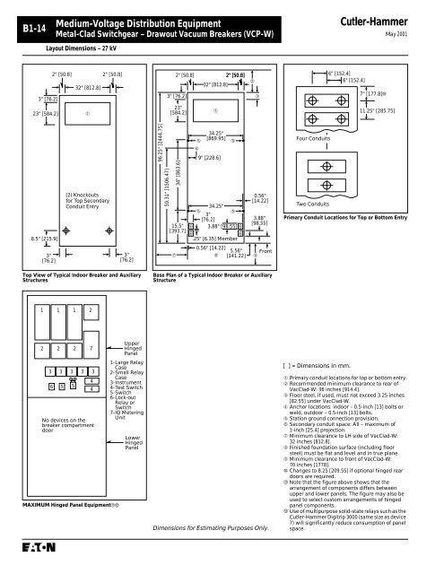
Top View of Typical Indoor Breaker and Auxiliary<br />
Structures<br />
1 1 1 2<br />
2 2 2 7<br />
3 3 3 3 3<br />
6 5 5<br />
32" [812.8]<br />
4<br />
4<br />
No devices on the<br />
breaker compartment<br />
door<br />
2" [50.8]<br />
MAXIMUM Hinged Panel Equipment<br />
➀<br />
(2) Knockouts<br />
for Top Secondary<br />
Conduit Entry<br />
3"<br />
[76.2]<br />
Upper<br />
Hinged<br />
Panel<br />
1-Large Relay<br />
Case<br />
2-Small Relay<br />
Case<br />
3-Instrument<br />
4-Test Switch<br />
5-Switch<br />
6-Lock-out<br />
Relay or<br />
Switch<br />
7-IQ Metering<br />
Unit<br />
Lower<br />
Hinged<br />
Panel<br />
96.25" [2444.75]<br />
59.31" [1506.47]<br />
3" [76.2]<br />
23"<br />
[584.2]<br />
15.5"<br />
[393.7]<br />
➆<br />
2" [50.8]<br />
34" [863.6]<br />
➄<br />
➃<br />
32" [812.8]<br />
2" [50.8]<br />
0.56" [14.22]<br />
5.56"<br />
➇ [141.22]<br />
0.56"<br />
[14.22]<br />
3.88"<br />
[98.55]<br />
Base Plan of a Typical Indoor Breaker or Auxiliary<br />
Structure<br />
Dimensions for Estimating Purposes Only.<br />
➀<br />
34.25"<br />
[869.95]<br />
9" [228.6]<br />
➄<br />
34.25"<br />
➄<br />
3"<br />
[76.2]<br />
➄<br />
➅ 3.88" [98.55] ➅<br />
➅<br />
➅<br />
.25" [6.35] Member<br />
➁<br />
➂<br />
Front<br />
➈<br />
Four Conduits<br />
Two Conduits<br />
<strong>Cutler</strong>-<strong>Hammer</strong><br />
6" [152.4]<br />
6" [152.4]<br />
7" [177.8]➉<br />
11.25" [285.75]<br />
May 2001<br />
Primary Conduit Locations for Top or Bottom Entry<br />
[ ] = Dimensions in mm.<br />
➀ Primary conduit locations for top or bottom entry.<br />
➁ Recommended minimum clearance to rear of<br />
VacClad-W: 36 inches [914.4].<br />
➂ Floor steel, if used, must not exceed 3.25 inches<br />
[82.55] under VacClad-W.<br />
➃ Anchor locations: indoor – 0.5-inch [13] bolts or<br />
weld, outdoor – 0.5-inch [13] bolts.<br />
➄ Station ground connection provision.<br />
➅ Secondary conduit space: All – maximum of<br />
1-inch [25.4] projection.<br />
➆ Minimum clearance to LH side of VacClad-W:<br />
32 inches [812.8].<br />
➇ Finished foundation surface (including floor<br />
steel) must be flat and level and in true plane.<br />
➈ Minimum clearance to front of VacClad-W:<br />
70 inches [1778].<br />
➉ Changes to 8.25 [209.55] if optional hinged rear<br />
doors are required.<br />
Note that the figure above shows that the<br />
arrangement of components differs between<br />
upper and lower panels. The figure may also be<br />
used to select custom arrangements of hinged<br />
panel components.<br />
Use of multipurpose solid-state relays such as the<br />
<strong>Cutler</strong>-<strong>Hammer</strong> Digitrip 3000 (same size as device<br />
7) will significantly reduce consumption of panel<br />
space.


