

Cutler-Hammer - Eaton Canada
Cutler-Hammer - Eaton Canada
Cutler-Hammer - Eaton Canada

Create successful ePaper yourself
Turn your PDF publications into a flip-book with our unique Google optimized e-Paper software.
<strong>Cutler</strong>-<strong>Hammer</strong><br />
May 2001<br />
The 3-phase, 3-wire system with 2-element<br />
watt-hour meters would require a set of<br />
two line-to-line voltage transformers. If<br />
line-to-ground potential is also required for<br />
a directional ground relay, then a set of three<br />
line-to-ground voltage transformers could<br />
be used to provide both line-to-line potential<br />
for the 2-element watt-hour meter and<br />
line-to-ground potential for the ground relay.<br />
Ground detection lights or relays for the<br />
ungrounded system requires three line-toground<br />
voltage transformers and a separate<br />
set is usually recommended for this purpose.<br />
The 3-phase, 4-wire, solidly grounded system<br />
usually requires three line-to-ground voltage<br />
transformers for 2 1 /2- or 3-element metering.<br />
Where synchronizing of generators or<br />
systems is involved, it is recommended that<br />
only line-to-line potential be used.<br />
Current Transformers<br />
The current transformer ratio is generally<br />
selected so that the maximum load current<br />
will read about 70 percent full scale on a standard<br />
5-ampere coil ammeter. Therefore, the<br />
current transformer primary rating should be<br />
140 to 150 percent of the maximum load current.<br />
Maximum system fault current can sometimes<br />
influence the current transformer ratio<br />
selection since the connected secondary<br />
devices have published one-second ratings.<br />
The zero-sequence current transformer is<br />
used for sensitive ground fault relaying or<br />
self-balancing primary current type machine<br />
differential protection. The zero-sequence<br />
current transformer is available with a<br />
nominal ratio of 50/5 or 100/5 and available<br />
opening size for power cables of 7.25 inches,<br />
special zero-sequence transformers with<br />
larger windows are also available.<br />
The minimum number of current transformers<br />
for circuit relaying and instruments is<br />
three current transformers, one for each<br />
phase or two-phase connected current<br />
transformers and one zero-sequence current<br />
transformer. Separate sets of current transformers<br />
are required for differential relays.<br />
The minimum pickup of a ground relay in the<br />
residual of three-phase connected current<br />
transformers is primarily determined by the<br />
current transformer ratio. The relay pickup can<br />
be reduced by adding one residual connected<br />
auxiliary current transformer. This connection<br />
is very desirable on main incoming and tie<br />
circuits of low resistance grounded circuits.<br />
Standard accuracy current transformers are<br />
normally more than adequate for most standard<br />
applications of microprocessor-based<br />
➀ Cable surge impedance 37Ω.<br />
➁ For solidly grounded 4160 volt system only or<br />
any type 2400 volt system.<br />
Medium-Voltage Distribution Equipment<br />
Metal-Clad Switchgear – Drawout Vacuum Breakers (VCP-W)<br />
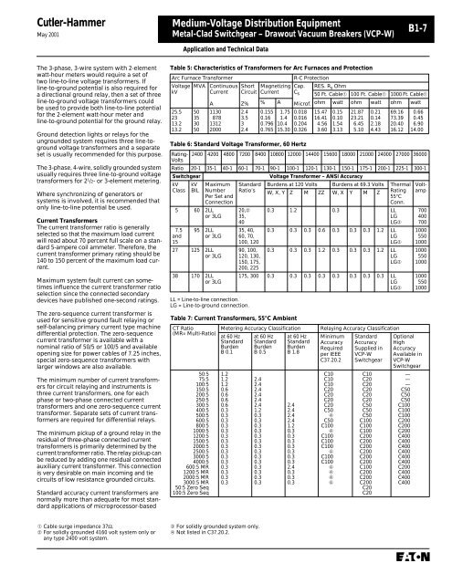
Table 6: Standard Voltage Transformer, 60 Hertz<br />
LL = Line-to-line connection.<br />
LG = Line-to-ground connection.<br />
B1-7<br />
Rating-<br />
Volts<br />
2400 4200 4800 7200 8400 10800 12000 14400 15600 18000 21000 24000 27000 36000<br />
Ratio 20-1 35-1 40-1 60-1 70-1 90-1 100-1 120-1 130-1 150-1 175-1 200-1 225-1 300-1<br />
Switchgear Voltage Transformer – ANSI Accuracy<br />
kV<br />
Class<br />
kV<br />
BIL<br />
Maximum<br />
Number<br />
Per Set and<br />
Connection<br />
5 60 2LL<br />
or 3LG<br />
7.5<br />
and<br />
15<br />
Application and Technical Data<br />
Table 5: Characteristics of Transformers for Arc Furnaces and Protection<br />
Arc Furnace Transformer R-C Protection<br />
Voltage<br />
kV<br />
MVA Continuous<br />
Current<br />
Short<br />
Circuit<br />
Magnetizing<br />
Current<br />
Cap.<br />
Cs RES. Rs Ohm<br />
50 Ft. Cable➀ 100 Ft. Cable➀ 1000 Ft. Cable➀<br />
A<br />
Z% % A Microf. ohm watt ohm watt ohm watt<br />
25.5 50 1130 2.4 0.155 1.75 0.018 15.47 0.15 21.87 0.21 69.16 0.66<br />
23 35 878 3.5 0.16 1.4 0.016 16.41 0.10 23.21 0.14 73.39 0.45<br />
13.2 30 1312 3 0.796 10.4 0.204 4.56 1.54 6.45 2.18 20.40 6.90<br />
13.2 50 2000 2.4 0.765 15.30 0.326 3.60 3.13 5.10 4.43 16.12 14.00<br />
95 2LL<br />
or 3LG<br />
27 125 2LL<br />
or 3LG<br />
38 170 2LL<br />
or 3LG<br />
Standard<br />
Ratio’s<br />
20,➁<br />
35,<br />
40<br />
35, 40,<br />
60, 70,<br />
100, 120<br />
90, 100,<br />
120, 130,<br />
150, 175,<br />
200, 225<br />
Table 7: Current Transformers, 55°C Ambient<br />
CT Ratio<br />
(MR= Multi-Ratio)<br />
50:5<br />
75:5<br />
100:5<br />
150:5<br />
200:5<br />
250:5<br />
300:5<br />
400:5<br />
500:5<br />
600:5<br />
800:5<br />
1000:5<br />
1200:5<br />
1500:5<br />
2000:5<br />
2500:5<br />
3000:5<br />
4000:5<br />
600:5 MR<br />
1200:5 MR<br />
2000:5 MR<br />
3000:5 MR<br />
50:5 Zero Seq<br />
100:5 Zero Seq<br />
Burdens at 120 Volts Burdens at 69.3 Volts Thermal<br />
W, X, Y Z M ZZ W, X Y M Z<br />
Rating<br />
55°C<br />
Conn.<br />
0.3 1.2 0.3 LL<br />
LG<br />
LG➂<br />
0.3 0.3 0.3 0.6 0.3 0.3 0.3 1.2 LL<br />
LG<br />
LG➂<br />
0.3 0.3 0.3 1.2 0.3 0.3 0.3 1.2 LL<br />
LG<br />
LG➂<br />
175, 300 0.3 0.3 0.3 0.3 0.3 0.3 0.3 0.3 LL<br />
LG<br />
LG➂<br />
Metering Accuracy Classification Relaying Accuracy Classification<br />
at 60 Hz<br />
Standard<br />
Burden<br />
B 0.1<br />
1.2<br />
1.2<br />
1.2<br />
0.6<br />
0.6<br />
0.6<br />
0.6<br />
0.3<br />
0.3<br />
0.3<br />
0.3<br />
0.3<br />
0.3<br />
0.3<br />
0.3<br />
0.3<br />
0.3<br />
0.3<br />
0.3<br />
0.3<br />
0.3<br />
0.3<br />
at 60 Hz<br />
Standard<br />
Burden<br />
B 0.5<br />
2.4<br />
2.4<br />
2.4<br />
2.4<br />
2.4<br />
2.4<br />
1.2<br />
0.3<br />
0.3<br />
0.3<br />
0.3<br />
0.3<br />
0.3<br />
0.3<br />
0.3<br />
0.3<br />
0.3<br />
0.3<br />
0.3<br />
0.3<br />
0.3<br />
➂ For solidly grounded system only.<br />
➃ Not listed in C37.20.2.<br />
at 60 Hz<br />
Standard<br />
Burden<br />
B 1.8<br />
2.4<br />
2.4<br />
2.4<br />
2.4<br />
1.2<br />
0.3<br />
0.3<br />
0.3<br />
0.3<br />
0.3<br />
0.3<br />
0.3<br />
2.4<br />
0.3<br />
0.3<br />
0.3<br />
Minimum<br />
Accuracy<br />
Required<br />
per IEEE<br />
C37.20.2<br />
C10<br />
C10<br />
C10<br />
C20<br />
C20<br />
C20<br />
C20<br />
C50 ➃<br />
C50<br />
C100 ➃<br />
C100<br />
C100<br />
C100 ➃<br />
C100<br />
C100 ➃➃➃➃<br />
Standard<br />
Accuracy<br />
Supplied in<br />
VCP-W<br />
Switchgear<br />
C10<br />
C20<br />
C20<br />
C20<br />
C20<br />
C20<br />
C50<br />
C50<br />
C50<br />
C100<br />
C100<br />
C100<br />
C200<br />
C200<br />
C200<br />
C200<br />
C200<br />
C200<br />
C100<br />
C200<br />
C200<br />
C200<br />
C20<br />
C20<br />
Voltamp<br />
700<br />
400<br />
700<br />
1000<br />
550<br />
1000<br />
1000<br />
550<br />
1000<br />
1000<br />
550<br />
1000<br />
Optional<br />
High<br />
Accuracy<br />
Available in<br />
VCP-W<br />
Switchgear<br />
—<br />
—<br />
—<br />
C50<br />
C50<br />
C50<br />
C100<br />
C100<br />
C100<br />
C200<br />
C200<br />
C200<br />
C400<br />
C400<br />
C400<br />
C400<br />
C400<br />
C400<br />
C200<br />
C400<br />
C400<br />
C400


