- Page 2 and 3: Advanced welding processes i
- Page 4 and 5: Advanced welding processes Technolo
- Page 6 and 7: Contents Preface ix Acknowledgement
- Page 8 and 9: Contents vii 10.4 Automated control
- Page 10 and 11: Welding has traditionally been rega
- Page 12 and 13: Acknowledgements I would like to ac
- Page 14 and 15: 1.1 Introduction Welding and joinin
- Page 16 and 17: An introduction to welding processe
- Page 18 and 19: An introduction to welding processe
- Page 20 and 21: An introduction to welding processe
- Page 22 and 23: Stage 1 Stage 2 An introduction to
- Page 24 and 25: Slag deposit on weld surface An int
- Page 26 and 27: ∑ no heavy slag - reduced post-we
- Page 28 and 29: An introduction to welding processe
- Page 30 and 31: Electro slag SAW multi wire SAW FCA
- Page 32 and 33: Weld metal used (kg m -1 ) 40 35 30
- Page 34 and 35: Advanced process development trends
- Page 36 and 37: % consumed 70 60 50 40 30 20 10 Adv
- Page 38 and 39: Advanced process development trends
- Page 40 and 41: Mains input Power regulation Contro
- Page 42 and 43: Welding power source technology 29
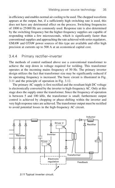
- Page 44 and 45: Welding power source technology 31
- Page 46 and 47: Welding power source technology 33
- Page 50 and 51: Three-phase transformer Three-phase
- Page 52 and 53: Mains input Welding power source te
- Page 54 and 55: Off line storage Operator interface
- Page 56 and 57: Welding power source technology 43
- Page 58 and 59: 4.2.1 Improved toughness Filler mat
- Page 60 and 61: Filler materials for arc welding 47
- Page 62 and 63: Flat strip Solidified slag on weld
- Page 64 and 65: Filler materials for arc welding 51
- Page 66 and 67: Filler materials for arc welding 53
- Page 68 and 69: Filler materials for arc welding 55
- Page 70 and 71: Filler materials for arc welding 57
- Page 72 and 73: Gases for advanced welding processe
- Page 74 and 75: Gases for advanced welding processe
- Page 76 and 77: CVN impact energy (J) 200 150 100 5
- Page 78 and 79: ∑ argon plus 15-25% carbon dioxid
- Page 80 and 81: 25 23 21 19 17 15 13 11 9 7 20 18 1
- Page 82 and 83: Gases for advanced welding processe
- Page 84 and 85: Ozone emission (ml min -1 ) 4 3 2 1
- Page 86 and 87: Table 5.3 Continued Argon + 1 to 7%
- Page 88 and 89: Advanced gas tungsten arc welding 7
- Page 90 and 91: Power source Advanced gas tungsten
- Page 92 and 93: Number of arc starts 35 30 25 20 15
- Page 94 and 95: Advanced gas tungsten arc welding 8
- Page 96 and 97: Advanced gas tungsten arc welding 8
- Page 98 and 99:
Water cooling 6.7 Dual-shielded GTA
- Page 100 and 101:
Advanced gas tungsten arc welding 8
- Page 102 and 103:
∑ low current: 0.1-15 A; ∑ inte
- Page 104 and 105:
Advanced gas tungsten arc welding 9
- Page 106 and 107:
Advanced gas tungsten arc welding 9
- Page 108 and 109:
Advanced gas tungsten arc welding 9
- Page 110 and 111:
Surface tension Surface tension Adv
- Page 112 and 113:
Advanced gas tungsten arc welding 9
- Page 114 and 115:
7.2.1 Globular drop transfer Metal
- Page 116 and 117:
Gas metal arc welding 103 projected
- Page 118 and 119:
Droplet forming 7.6 Drop spray tran
- Page 120 and 121:
Number of counts 100 80 60 40 20 0
- Page 122 and 123:
Metal cored Rutile Basic Self-shiel
- Page 124 and 125:
F d Fem F v F st F g 7.13 Balance o
- Page 126 and 127:
Gas metal arc welding 113 is the cu
- Page 128 and 129:
Stick out Dip transfer Pulse/spray
- Page 130 and 131:
Gas metal arc welding 117 V = M + A
- Page 132 and 133:
Voltage (V) 50 40 30 20 10 Gas meta
- Page 134 and 135:
Pulse current t p 7.23 Pulsed trans
- Page 136 and 137:
Gas metal arc welding 123 The mean
- Page 138 and 139:
Wire feed rate (m min -1 ) 11 10.5
- Page 140 and 141:
Gas metal arc welding 127 Improveme
- Page 142 and 143:
Gas metal arc welding 129 and a num
- Page 144 and 145:
Current (A) 500 400 300 200 100 0 G
- Page 146 and 147:
Pulse amplitude (A) 500 400 300 200
- Page 148 and 149:
Gas metal arc welding 135 otherwise
- Page 150 and 151:
High-energy density processes 137
- Page 152 and 153:
High-energy density processes 139 P
- Page 154 and 155:
Arc voltage 30 25 20 15 10 High-ene
- Page 156 and 157:
High-energy density processes 143 N
- Page 158 and 159:
Reflecting mirror Laser cavity Powe
- Page 160 and 161:
High-energy density processes 147 H
- Page 162 and 163:
Laser beam Gas lens Plasma control
- Page 164 and 165:
High-energy density processes 151 P
- Page 166 and 167:
High-energy density processes 153 M
- Page 168 and 169:
High-energy density processes 155 a
- Page 170 and 171:
High-energy density processes 157 l
- Page 172 and 173:
High-energy density processes 159 p
- Page 174 and 175:
8.4.5 Practical considerations High
- Page 176 and 177:
Sliding particle stop Undeflected b
- Page 178 and 179:
9.1 Introduction 9 Narrow-gap weldi
- Page 180 and 181:
6-16 mm Parallel-sided with backing
- Page 182 and 183:
Water cooling Main Shielding-gas po
- Page 184 and 185:
Narrow-gap welding techniques 171 T
- Page 186 and 187:
9.7 ‘Twist arc’ narrow-gap GMAW
- Page 188 and 189:
GMAW torch The NOW process GMAW tor
- Page 190 and 191:
Narrow-gap welding techniques 177 T
- Page 192 and 193:
10.1 Introduction 10 Monitoring and
- Page 194 and 195:
Monitoring and control of welding p
- Page 196 and 197:
PROJECT: WELDING CODE : WELDING PRO
- Page 198 and 199:
TYPE TOUGHNESS TEST TYPE No. TEMP R
- Page 200 and 201:
Monitoring and control of welding p
- Page 202 and 203:
Monitoring and control of welding p
- Page 204 and 205:
Data RAM ADC I/O device Monitoring
- Page 206 and 207:
Monitoring and control of welding p
- Page 208 and 209:
Current I(A) 150 140 130 120 110 Mo
- Page 210 and 211:
Table 10.5 Stability criteria Monit
- Page 212 and 213:
Monitoring and control of welding p
- Page 214 and 215:
Monitoring and control of welding p
- Page 216 and 217:
Monitoring and control of welding p
- Page 218 and 219:
Monitoring and control of welding p
- Page 220 and 221:
Monitoring and control of welding p
- Page 222 and 223:
Monitoring and control of welding p
- Page 224 and 225:
CCD camera Travel direction Torch M
- Page 226 and 227:
Monitoring and control of welding p
- Page 228 and 229:
Monitoring and control of welding p
- Page 230 and 231:
Monitoring and control of welding p
- Page 232 and 233:
Welding automation and robotics 219
- Page 234 and 235:
Welding automation and robotics 221
- Page 236 and 237:
Welding automation and robotics 223
- Page 238 and 239:
Welding automation and robotics 225
- Page 240 and 241:
Welding automation and robotics 227
- Page 242 and 243:
Welding automation and robotics 229
- Page 244 and 245:
Welding automation and robotics 231
- Page 246 and 247:
Welding automation and robotics 233
- Page 248 and 249:
Table 11.1 Robot applications Weldi
- Page 250 and 251:
Welding automation and robotics 237
- Page 252 and 253:
Welding automation and robotics 239
- Page 254 and 255:
Welding automation and robotics 241
- Page 256 and 257:
∑ evaluate alternatives; ∑ eval
- Page 258 and 259:
Option Manual metal arc Gas metal a
- Page 260 and 261:
Appendices Appendices 247
- Page 262 and 263:
Arc Metal arc Manual metal arc Resi
- Page 264 and 265:
Tensile strength Appendices 251 Des
- Page 266 and 267:
Appendices 253 Exx16 Basic low-hydr
- Page 268 and 269:
GMAW stainless steel c Wire feed sp
- Page 270 and 271:
Appendix 4 American, Australian and
- Page 272 and 273:
Appendices 259 Carbon Manganese ste
- Page 274 and 275:
Consumable type Features Applicatio
- Page 276 and 277:
Appendix 7 Plasma keyhole welding o
- Page 278 and 279:
References [1] British Standards In
- Page 280 and 281:
References 267 [40] Anon, 1989 ‘S
- Page 282 and 283:
References 269 [88] Boughton P and
- Page 284 and 285:
References 271 Century Conference (
- Page 286 and 287:
References 273 [178] Benn B, 1988
- Page 288 and 289:
References 275 [224] Philpott M L,
- Page 290 and 291:
References 277 [269] UK Patent 8411
- Page 292 and 293:
Activated TIG (A-TIG) 91, 97 adapti
- Page 294 and 295:
digital measuring systems 189-90 di
- Page 296 and 297:
high-frequency high-voltage arc ini
- Page 298 and 299:
current measurement 194-6 determina
- Page 300 and 301:
carbon dioxide 63-4, 64-6 chlorine