Y-IM-Single Package AC and Single Package Gas/Electric Units ...
Y-IM-Single Package AC and Single Package Gas/Electric Units ...
Y-IM-Single Package AC and Single Package Gas/Electric Units ...

You also want an ePaper? Increase the reach of your titles
YUMPU automatically turns print PDFs into web optimized ePapers that Google loves.
127083-Y<strong>IM</strong>-B-0606<br />
by inadequate supply air flow occurs, thus shutting down the<br />
heater <strong>and</strong> energizing the blower.<br />
The auxiliary limit switch is wired in series with the limit<br />
switch. As such, the UCB cannot distinguish the auxiliary limit<br />
<strong>and</strong> the gas heat limit switch operation except the auxiliary is<br />
manual reset. Consequently, the control will respond in the<br />
same manner as outlined above under “Limit Switch”.<br />
TABLE 46: GAS HEAT L<strong>IM</strong>IT CONTROL SETTINGS 1<br />
Unit Main Limit Setting<br />
Size Opt.<br />
°F<br />
DF078<br />
10<br />
15<br />
215<br />
195<br />
DF090<br />
10<br />
15<br />
165<br />
165<br />
DF102<br />
10<br />
15<br />
165<br />
165<br />
DF120<br />
15<br />
20<br />
195<br />
160<br />
1. Rollout = 300°F, Auxiliary Limit = 200°F<br />
The ICB monitors the Pressure <strong>and</strong> Rollout switches of gas<br />
heat units.<br />
The control circuit includes the following safety controls:<br />
PRESSURE SWITCH (PS)<br />
Once the draft motor has reached full speed <strong>and</strong> closes the<br />
pressure switch during a normal ignition sequence, if the<br />
pressure sw opens for 2 seconds, the GV will be de-energized,<br />
the ignition cycle is aborted, <strong>and</strong> the ICB flashes the<br />
appropriate code. See Table 55 Ignition Control Flash Codes.<br />
The draft motor is energized until the pressure switch closes<br />
or “W1” is lost.<br />
ROLLOUT SWITCH (ROS)<br />
The rollout switch is wired in series with the pressure switch.<br />
As such, the ICB cannot distinguish the rollout switch operation<br />
from that of the pressure switch.<br />
Consequently, the control will only respond in the same manner<br />
as outlined above under “Pressure Switch”. An open rollout<br />
will inhibit the gas valve from actuating.<br />
INTERNAL MICROPROCESSOR FAILURE<br />
If the ICB detects an internal failure, it will cease all outputs,<br />
ignore inputs, <strong>and</strong> display the proper flash code for control<br />
replacement. The ICB remains in this condition until replaced.<br />
FLASH CODES<br />
The UCB will initiate a flash code associated with errors<br />
within the system. Refer to UNIT CONTROL BOARD FLASH<br />
CODES Table 54.<br />
RESETS<br />
Remove the call for heating by lowering the thermostat setting<br />
lower than the conditioned space temperature. This<br />
resets any flash codes.<br />
GAS HEAT ANTICIPATOR SETPOINTS<br />
It is important that the anticipator setpoint be correct. Too<br />
high of a setting will result in longer heat cycles <strong>and</strong> a greater<br />
temperature swing in the conditioned space. Reducing the<br />
value below the correct setpoint will give shorter “ON cycles<br />
<strong>and</strong> may result in the lowering of the temperature within the<br />
conditioned space. Refer to Table 47 for the required gas<br />
heat anticipator setting.<br />
TABLE 47: GAS HEAT ANTICIPATOR SETPOINTS<br />
START-UP (COOLING)<br />
PRESTART CHECK LIST<br />
SETTING, AMPS<br />
W1 W2<br />
0.65 0.1<br />
/ ) 5<br />
5 7 2 2 ;<br />
2 12 - * 7 4 - 4<br />
* 7 4 - 4 * 4 ) + - 6<br />
1/ 16 4<br />
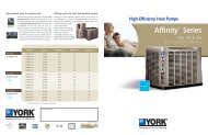
FIGURE 28 - TYPICAL FLAME<br />
After installation has been completed:<br />
1. Check the electrical supply voltage being supplied. Be<br />
sure that it is the same as listed on the unit nameplate.<br />
2. Set the room thermostat to the off position.<br />
3. Turn unit electrical power on.<br />
4. Set the room thermostat fan switch to on.<br />
5. Check indoor blower rotation.<br />
• If blower rotation is in the wrong direction. Refer to<br />
Phasing Section in general information section.<br />
• Check blower drive belt tension.<br />
6. Check the unit supply air (CFM).<br />
7. Measure evaporator fan motor's amp draw.<br />
8. Set the room thermostat fan switch to off.<br />
9. Turn unit electrical power off.<br />
* 7 4 - 4 . ) -<br />
* 7 - ;<br />
0 - ) 6 - : + 0 ) / - 4 6 7 * -<br />
Unitary Products Group 53