Important Placement Instructions Enclosed See Lifting - Haas ...
Important Placement Instructions Enclosed See Lifting - Haas ...
Important Placement Instructions Enclosed See Lifting - Haas ...

You also want an ePaper? Increase the reach of your titles
YUMPU automatically turns print PDFs into web optimized ePapers that Google loves.
<strong>Haas</strong> Technical Publications<br />
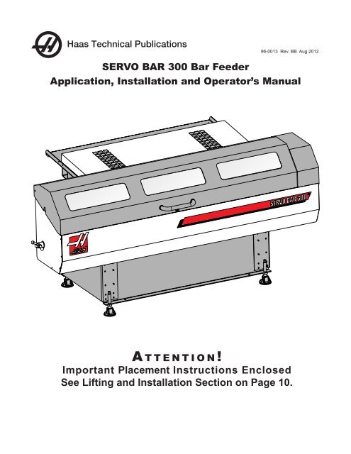
SERVO BAR 300 Bar Feeder<br />
96-0013 Rev. BB Aug 2012<br />
Application, Installation and Operator’s Manual<br />
A t t e n t i o n !<br />
<strong>Important</strong> <strong>Placement</strong> <strong>Instructions</strong> <strong>Enclosed</strong><br />
<strong>See</strong> <strong>Lifting</strong> and Installation Section on Page 10.
Original <strong>Instructions</strong><br />
<strong>Haas</strong> Technical Publications<br />
Installation, Application and Operator’s Manual<br />
Table of Contents<br />
Servo Bar Feeder Overview ................................................................5<br />
Declaration of Incorporation ................................................................6<br />
Safety ..................................................................................................7<br />
Lathe Preparation ...............................................................................8<br />
Spindle Liners ............................................................................8<br />
ST-10 Bar Feeder Interface Plate ..............................................8<br />
<strong>Lifting</strong> and Installation .........................................................................10<br />
Uncrating and Assembly ............................................................11<br />
Bar Feeder Positioning ..............................................................13<br />
Bar Feeder Cable Routing ........................................................14<br />
Cable Connections - Bar Feeder ...............................................16<br />
Electrical Installation ............................................................................17<br />
Installing the Interface ...............................................................17<br />
Cable Connections - Lathe ........................................................20<br />
Change Parameters ..................................................................24<br />
Bar Feeder Leveling ............................................................................25<br />
Verify Alignment ...................................................................................25<br />
Establish End of Bar Position ..............................................................26<br />
Operation .............................................................................................27<br />
Introduction ................................................................................27<br />
Recommendations ....................................................................28<br />
Modes of Operation ...................................................................30<br />
Servo Bar 300 Quick Start Guide ........................................................31<br />
Setup ...................................................................................................32<br />
Transfer Tray Adjustment ..........................................................32<br />
Bar Feeder Push Rod Clearance ..............................................33<br />
Charging Tray Height Adjustments ............................................33<br />
Small Diameter Bars (.375"/9.5mm to .75"/19mm) ....................34<br />
Changing the Push Rod ............................................................34<br />
Reference Position Setup ..........................................................39<br />
Bar Feed Recovery ..............................................................................39<br />
Programming .......................................................................................40<br />
G Code Description ...................................................................40<br />
Q Mode Descriptions .................................................................40<br />
Sample Program .......................................................................42<br />
Counter ......................................................................................44<br />
Machining Short Bars ................................................................45<br />
Using the Bar 300 as a Stop ................................................................46<br />
Macro Variables ...................................................................................47<br />
Bar Feeder Compatibility .....................................................................48<br />
ST / DS Models Bar Feeder Compatibility .................................48<br />
GT / SL / TL (Subspindle) Models Bar Feeder Compatibility .....49<br />
Compatibility Notes ..................................................................50<br />
Bar Feeder Height Adjustment ............................................................51<br />
Method 1: Height Adjustment - Forklift ......................................52<br />
Method 2: Height Adjustment - <strong>Lifting</strong> Straps ............................53<br />
Method 3: Height Adjustment - Jack Screws .............................54<br />
SL Models - Lathe Positioning .............................................................56<br />
Maintenance ........................................................................................57<br />
96-0013, Rev. BB Aug 2012<br />
PAgE 3 OF 66
<strong>Haas</strong> Technical Publications<br />
Installation, Application and Operator’s Manual<br />
Bar Feeder External Dimensions .........................................................59<br />
Bar Feeder Parts List ...........................................................................60<br />
Bar Feeder Sheetmetal .............................................................60<br />
Bar Feeder External Parts .........................................................61<br />
Bar Feeder Internal Parts ..........................................................63<br />
Bar Feeder Detail Parts List ......................................................65<br />
PAgE 4 OF 66<br />
96-0013, Rev. BB Aug 2012<br />
Original <strong>Instructions</strong>
Servo Bar Feeder Overview<br />
The <strong>Haas</strong> Bar Feeder features a heavy-duty yet compact design, with up to 3 1/8" (79 mm) bar<br />
capacity and a footprint of only 4.5' x 8' (1.38 m x 2.43 m). Designed to boost productivity and<br />
streamline turning operations, this servo-driven Bar Feeder is built by <strong>Haas</strong> exclusively for <strong>Haas</strong> CNC<br />
lathes.<br />
Charging Tray<br />
Charging<br />
Tray<br />
Adjustment<br />
Screw<br />
Liner Adapter<br />
Spanner Wrench<br />
Storage<br />
Height Adjustment<br />
Handle<br />
Original <strong>Instructions</strong><br />
Charging Tray<br />
Cover<br />
Storage Tray<br />
Set-up Lid Lock<br />
<strong>Haas</strong> Technical Publications<br />
Installation, Application and Operator’s Manual<br />
Charging Tray<br />
Push Rod Assy<br />
Transfer Tray<br />
For Servo Bar Feeder shipping dimensions see ES0428.<br />
96-0013, Rev. BB Aug 2012<br />
Set-up Lid<br />
End of Bar<br />
Switch<br />
Transfer Tray<br />
Charging<br />
Position<br />
Charging<br />
Tray<br />
PAgE 5 OF 66
Product: Servo Bar 300 Magazine Bar Feeder<br />
Declaration of Incorporation<br />
Model: _____________________ Serial Number: _____________________<br />
Manufactured By: <strong>Haas</strong> Automation, Inc.<br />
2800 Sturgis Road, Oxnard, CA 93030 805-278-1800<br />
We declare, in sole responsibility, that the above listed product, to which this declaration refers, cannot function independently and does not<br />
change the function of the machine it is attached to. The Servo Bar 300 when incorporated into Hass CNC Lather( turning centers), complies<br />
with the regulations as outlined in the CE directive for turning centers.<br />
· Machinery Directive 2006/42/EC<br />
· Electromagnetic Compatibility Directive 2004/108/EC<br />
· Low Voltage Directive 2006/95/EC<br />
Additional Standards:<br />
· EN 60204-1:2006/A1:2009<br />
· EN 614-1:2006+A1:2009<br />
· EN 894-1:1997+A1:2008<br />
· EN 13849-1:2008/AC:2009<br />
· EN 14121-1:2007<br />
RoHS: COMPLIANT by Exemption per producer documentation. Exception by:<br />
a) Large scale stationary industrial tool<br />
b) Monitoring and control systems<br />
c) Lead as an alloying element in steel, aluminum and copper<br />
Person authorized to compile technical file:<br />
Patrick Goris<br />
Address: <strong>Haas</strong> Automation Europe<br />
Mercuriusstraat 28<br />
B-1930 Zaventem<br />
Belgium<br />
USA: <strong>Haas</strong> Automation certifies this machine to be in compliance with the OSHA and ANSI design and manufacturing standards listed below.<br />
Operation of this machine will be compliant with the below-listed standards only as long as the owner and operator continue to follow the<br />
operation, maintenance, and training requirements of these standards.<br />
· OSHA 1910.212 - General Requirements for All Machines<br />
· ANSI B11.5-1984 (R1994) Lathes<br />
· ANSI B11.19-2003 Performance Criteria for Safeguarding<br />
· ANSI B11.22-2002 Safety Requirements for Turning Centers and Automatic Numerically Controlled Turning Machines<br />
· ANSI B11.TR3-2000 Risk Assessment and Risk Reduction - A Guideline to Estimate, Evaluate, and Reduce Risks Associated with<br />
Machine Tools<br />
CANADA: As the original equipment manufacturer, we declare that the listed products comply with regulation as outlined in the Pre-Start Health<br />
and Safety Reviews Section 7 of Regulation 851 of the Occupational Health and Safety Act Regulations for Industrial Establishments for machine<br />
guarding provisions and standards.<br />
Further this document satisfies the notice in writing provision for exemption from Pre-Start inspection for the listed machinery as outlined in the<br />
Ontario Health and Safety Guidelines, PSR Guidelines dated April 2001. The PSR Guideline allows that notice in writing from the original equipment<br />
manufacture for conformity to applicable standards as acceptable for the exemption from Pre-Start Health and Safety Review.<br />
PAgE 6 OF 66<br />
<strong>Haas</strong> Technical Publications<br />
Installation, Application and Operator’s Manual<br />
96-0013, Rev. BB Aug 2012<br />
Original <strong>Instructions</strong>
Safety<br />
Before starting any work on the machine, read this manual and the warning labels on the machine.<br />
Ensure that all personnel using this equipment understand the hazards that are present with<br />
automatic equipment. Individuals not associated with production or who are unfamiliar with this type<br />
of equipment must be kept away.<br />
The Bar Feeder is controlled by the lathe and may start at any time.<br />
Cautions<br />
• Read and follow all safety instructions, warnings and cautions associated with this machine.<br />
• Read and follow all machine maintenance, setup and operation instructions.<br />
• Read and follow spindle liner installation and use instructions.<br />
• Disconnect all sources of power before maintaining, servicing or altering setup of this machine.<br />
• Lethal voltages may be present; disconnect main power before servicing this machine.<br />
• Incorrect setup of Bar Feeder or spindle liner tubes can cause workpiece or rotating parts to be<br />
ejected with lethal force and may destroy machine(s).<br />
• Follow all setup precautions and verify correct setup before automatic operation.<br />
• The Bar Feeder is automatically controlled and may start at any time.<br />
• Warn persons nearby about automatic machine in operation.<br />
• Do not operate lathe or Bar Feeder with access doors or operator doors open.<br />
• Moving parts inside; keep body, limbs and foreign objects out of machine during operation.<br />
• No user serviceable parts inside machine. Contact your dealer for approved service.<br />
• Replace worn or broken Bar Feeder components or spindle liners immediately.<br />
• Do not alter or modify the Bar Feeder in any way.<br />
• Do not use Bar Feeder beyond recommended limits of speed or material capacity.<br />
• Do not use Bar Feeder without proper size spindle liner installed.<br />
• Do not operate or allow others to operate Bar Feeder until receiving user and safety training.<br />
• Stop spindle if vibration or noise is present. Find and correct condition before operating<br />
machine.<br />
• Do not attach dead stop, bar pilot bushing or anti-vibration collars to the body of the rotating union<br />
(chuck closing cylinder) of lathe. Violent, catastrophic failure of rotating union can occur at high spindle<br />
RPM if rotating union is damaged by body attached devices.<br />
• Do not operate spindle with bar material unclamped or extending beyond the spindle liner.<br />
• Damage resulting from incorrect or improper use will not be covered under the machine(s)<br />
warranty.<br />
• Do not start or continue a machine cycle unless you are certain of the part off allowance.<br />
Original <strong>Instructions</strong><br />
<strong>Haas</strong> Technical Publications<br />
Installation, Application and Operator’s Manual<br />
96-0013, Rev. BB Aug 2012<br />
PAgE 7 OF 66
Lathe Preparation<br />
Spindle Liners<br />
When using a Bar Feeder with an ST-30 Big Bore lathe, you must install spindle liners. For all other<br />
lathes, spindle liners are optional when using a Bar Feeder.<br />
<strong>See</strong> ES0603 for information on all spindle liner kits, including installation and part reorder<br />
information.<br />
ST-10 Bar Feeder Interface Plate<br />
ST-10 lathes with a Bar Feeder may need an additional plate installed at the Bar Feeder interface to<br />
prevent coolant spray from exiting the coolant collector.<br />
You should install this plate before installing the Bar Feeder for the first time, but you can install and<br />
remove this plate at any time while the Bar Feeder is installed.<br />
Before You Begin! Remove any bar stock between the Bar Feeder and the lathe spindle.<br />
1. For clarity, the Bar Feeder is not shown in<br />
the illustrations for this procedure.<br />
If you are installing the interface plate when<br />
the bar feedeer is already installed, you<br />
DO NOT need to remove the Bar Feeder to<br />
complete this procedure.<br />
2. Align the interface plate with the liner<br />
adapter and the tabs on the coolant<br />
collector.<br />
PAgE 8 OF 66<br />
<strong>Haas</strong> Technical Publications<br />
Installation, Application and Operator’s Manual<br />
96-0013, Rev. BB Aug 2012<br />
Original <strong>Instructions</strong>
3. Push the the interface plate in, then slide it<br />
down so the coolant collector tabs lock it in<br />
place.<br />
If the interface plate does not slide into<br />
place, tap it gently into place with a dead<br />
blow hammer.<br />
4. With the small hole on the flange at the top<br />
(A), put the bar tube into the interface plate.<br />
The mounting tabs on the tube fit into the<br />
slots on the plate. For clarity, inset view (B)<br />
illustrates this from the other side of the<br />
plate.<br />
5. Turn the bar tube clockwise until the small<br />
hole in the bar tube flange (A) lines up with<br />
the small hole in the interface plate (B).<br />
To remove the interface plate, remove any bar between the lathe and the Bar Feeder, turn the<br />
bar tube counter-clockwise to remove the tube, then pull the interface plate up and out of the<br />
coolant collector.<br />
Original <strong>Instructions</strong><br />
<strong>Haas</strong> Technical Publications<br />
Installation, Application and Operator’s Manual<br />
96-0013, Rev. BB Aug 2012<br />
A<br />
B<br />
B<br />
A<br />
PAgE 9 OF 66
<strong>Lifting</strong> and Installation<br />
A t t e n t i o n !<br />
<strong>Important</strong> <strong>Placement</strong><br />
<strong>Instructions</strong> <strong>Enclosed</strong><br />
Please read these instructions for proper Bar Feeder placement.<br />
The Bar Feeder is shipped in only one of two height configurations to match the models<br />
indicated.<br />
ST-10, ST-20 Series. ST-30, DS-30 Series<br />
<strong>See</strong> Bar Feeder Compatibility on page 48 and Height Adjustment on page 51 for<br />
other lathe model compatibility and height adjustment procedures.<br />
PAgE 10 OF 66<br />
<strong>Haas</strong> Technical Publications<br />
Installation, Application and Operator’s Manual<br />
96-0013, Rev. BB Aug 2012<br />
Original <strong>Instructions</strong>
Original <strong>Instructions</strong><br />
<strong>Haas</strong> Technical Publications<br />
Installation, Application and Operator’s Manual<br />
Uncrating and Assembly<br />
Do not position the Bar Feeder until after installing the Liner Adapter Kit.<br />
<strong>See</strong> Lathe Preparation on page 8.<br />
1. Carefully remove the alignment plate from the charging table and accessories from the Bar<br />
Feeder and pallet.<br />
2. Remove the four lag bolts holding the base to the pallet and lift the machine off of the pallet.<br />
3. Remove the zip ties holding the push rod in place.<br />
96-0013, Rev. BB Aug 2012<br />
PAgE 11 OF 66
4. Reposition the height adjustment shaft.<br />
Loosen the set screw on the locking collar as<br />
shown. Turn the height adjustment shaft until<br />
the inside locking collar meets against the<br />
bulkhead. Reposition the outside collet and<br />
tighten the set screw.<br />
5. Install the height adjustment handle.<br />
PAgE 12 OF 66<br />
<strong>Haas</strong> Technical Publications<br />
Installation, Application and Operator’s Manual<br />
96-0013, Rev. BB Aug 2012<br />
Loosen<br />
Screw<br />
Tighten<br />
Screw<br />
Original <strong>Instructions</strong>
Original <strong>Instructions</strong><br />
<strong>Haas</strong> Technical Publications<br />
Installation, Application and Operator’s Manual<br />
Bar Feeder Positioning<br />
1. Lift the left side of the lathe off the leveling pads and position the alignment plate under the two<br />
leveling screws. Lower the lathe and re-level.<br />
Bar Feeder<br />
Leveling<br />
Pad<br />
ST/DS Lathe Alignment Plate<br />
BAR FEEDER<br />
Leveling<br />
Screw<br />
Alignment<br />
Plate<br />
ST-10<br />
25-1026B<br />
DS-30<br />
ST-20/30<br />
25-1576B<br />
25-10195<br />
96-0013, Rev. BB Aug 2012<br />
LATHE<br />
Big Bore, Gearbox, Extended Push<br />
Lathes with Coolant Collector<br />
Extension<br />
Standard Lathes<br />
2. Lift the Bar Feeder with a pallet jack or forklift. Align the right side leveling screws to the<br />
appropriate holes in the alignment plate. Align the leveling pads with the leveling screws and<br />
lower the Bar Feeder onto the pads.<br />
PAgE 13 OF 66
Bar Feeder Cable Routing<br />
Warning!<br />
Bar Feeder cables must be routed correctly to avoid damage.<br />
NOTE: Refer to cable labels to make sure the correct cable ends are in the proper location.<br />
1 L1 3 L2 5 L3<br />
1 L1 3 L2 5 L3<br />
21<br />
21<br />
NC 32<br />
NC 32<br />
CA7<br />
DELTA CA7<br />
WYE<br />
DANGER!<br />
-37<br />
-37<br />
VECTOR<br />
22<br />
22 HIGH VOLTAGE!<br />
NO USER SERVICEABLE PARTS<br />
D RIVE<br />
NC 31<br />
NC 31 INSIDE. HIGH VOLTAGE LIGHT<br />
2 T1 4 T2 6 T3<br />
2 T1 4 T2 6 T3<br />
MUST BE OUT BEFORE SERVICE.<br />
CLOSED LOOP<br />
MADE IN USA<br />
TB2<br />
240V OUT<br />
325 VDC<br />
INPUT<br />
OUTPUT<br />
TO SERVOS 230 VAC 3 GROUND<br />
TO MOTOR<br />
+ - A B C<br />
A B C<br />
1 2 3 4 5 6 7 8 9 10 11<br />
260-244 V 243-227 V 226-211 V 210-195 V<br />
INCOMING LINE VOLTAGE TAPS (74,75,76)<br />
DANGER!!! HIGH VOLTAGE DANGER!!!<br />
32-1579A<br />
Alignment Plate<br />
Trough<br />
32-1405<br />
On ST-10/20 series it may be necessary to remove the storage tray to route the cables and gain<br />
access to the cable connecting plate.<br />
1. Raise the charging tray to its highest<br />
position.<br />
PAgE 14 OF 66<br />
<strong>Haas</strong> Technical Publications<br />
Installation, Application and Operator’s Manual<br />
96-0013, Rev. BB Aug 2012<br />
Original <strong>Instructions</strong>
2. Remove the storage tray to gain access to<br />
the Bar Feeder bracket and cable routing.<br />
3. Feed Cable 32-1579A through the opening<br />
in the lathe side of the Bar Feeder and<br />
down through the aligment plate trough.<br />
Original <strong>Instructions</strong><br />
<strong>Haas</strong> Technical Publications<br />
Installation, Application and Operator’s Manual<br />
Do not route cables over the side of the Bar Feeder. This will result in pinched or broken cables.<br />
Route cables under the machine using strain reliefs.<br />
x 1<br />
x 4<br />
96-0013, Rev. BB Aug 2012<br />
PAgE 15 OF 66<br />
`
1. Connect cable 32-1579 to the Bar<br />
Feeder. Use cable ties to secure the<br />
connectors under the protective plate.<br />
Ground the cable using the cable clamp<br />
screw.<br />
2. Connect cable 32-1405 to the socket on<br />
the Bar Feeder bracket.<br />
3. Install the storage tray.<br />
4. Adjust the charging tray to the desired<br />
position. For most round stock, the angle<br />
of the charging tray should be set to 5°<br />
above horizontal.<br />
PAgE 16 OF 66<br />
<strong>Haas</strong> Technical Publications<br />
Installation, Application and Operator’s Manual<br />
Cable Connections - Bar Feeder<br />
x 1<br />
END OF BAR O LOAD LOAD BAR<br />
HOME SW SPARE SPARE<br />
EXT PUSH LOAD Q/B<br />
x 4<br />
96-0013, Rev. BB Aug 2012<br />
MADE IN U.S.A. 32-1405<br />
32-1579<br />
Original <strong>Instructions</strong>
1. Press the Power Off button. Open the<br />
cabinet door. Turn off and lock out system<br />
power.<br />
2. Ensure that the 320V bus on the Vector<br />
Drive has been completely discharged<br />
before beginning work.<br />
Original <strong>Instructions</strong><br />
<strong>Haas</strong> Technical Publications<br />
Installation, Application and Operator’s Manual<br />
Electrical Installation<br />
Installing the Interface<br />
DANGER!<br />
HIGH VOLTAGE!<br />
NO USER SERVICEABLE PARTS<br />
INSIDE. HIGH VOLTAGE LIGHT<br />
MUST BE OUT BEFORE SERVICE.<br />
96-0013, Rev. BB Aug 2012<br />
MADE IN USA<br />
VECTOR<br />
D RIVE<br />
CLOSED LOOP<br />
I<br />
O<br />
325 VDC<br />
INPUT<br />
OUTPUT<br />
TO SERVOS 230 VAC 3 GROUND<br />
TO MOTOR<br />
+ - A B C<br />
A B C<br />
1 2 3 4 5 6 7 8 9 10 11<br />
PAgE 17 OF 66
3. Remove the Maincon cover.<br />
4. Add the Bar Feeder Amplifier (P/N 32-<br />
5550D) into its assigned slot.<br />
5. Remove the cable channel covers.<br />
PAgE 18 OF 66<br />
<strong>Haas</strong> Technical Publications<br />
Installation, Application and Operator’s Manual<br />
x4<br />
96-0013, Rev. BB Aug 2012<br />
OBSERVE PRECAUTIONS FOR HANDLING ELECTROSTATIC SENSITIVE DEVICES<br />
Original <strong>Instructions</strong>
6. Attach the jumpers between the High<br />
Voltage Power connection of the closest<br />
amp and the Bar Feeder amp.<br />
Original <strong>Instructions</strong><br />
<strong>Haas</strong> Technical Publications<br />
Installation, Application and Operator’s Manual<br />
96-0013, Rev. BB Aug 2012<br />
PAgE 19 OF 66
1. Route the cables through the alignment<br />
plate trough and up thorough the bottom of<br />
the control cabinet.<br />
2. Plug the Bar Feeder encoder cable into the<br />
Y-axis port (P7) on the Maincon PCB.<br />
Cable Connections - Lathe<br />
C200<br />
S3<br />
LINE 1:<br />
LINE 2:<br />
LINE 3:<br />
U99<br />
U104<br />
U83<br />
U88<br />
U89<br />
J9<br />
J21<br />
U146<br />
RP77<br />
RP86<br />
RP83<br />
RP8<br />
RP79 1<br />
U86<br />
1 L1 3 L2 5 L3<br />
1 L1 3 L2 5 L3<br />
21<br />
21<br />
NC 32<br />
NC 32<br />
CA7<br />
DELTA CA7<br />
WYE<br />
DANGER!<br />
-37<br />
-37<br />
VECTOR<br />
22<br />
22 HIGH VOLTAGE!<br />
NO USER SERVICEABLE PARTS<br />
D RIVE<br />
NC 31<br />
NC 31 INSIDE. HIGH VOLTAGE LIGHT<br />
2 T1 4 T2 6 T3<br />
2 T1 4 T2 6 T3<br />
MUST BE OUT BEFORE SERVICE.<br />
CLOSED LOOP<br />
MADE IN USA<br />
TB2<br />
240V OUT<br />
325 VDC<br />
INPUT<br />
OUTPUT<br />
TO SERVOS 230 VAC 3 GROUND<br />
TO MOTOR<br />
+ - A B C<br />
A B C<br />
1 2 3 4 5 6 7 8 9 10 11<br />
260-244 V 243-227 V 226-211 V 210-195 V<br />
INCOMING LINE VOLTAGE TAPS (74,75,76)<br />
DANGER!!! HIGH VOLTAGE DANGER!!!<br />
C537<br />
RP98<br />
C78<br />
C765<br />
C536<br />
RP3<br />
1<br />
RP116<br />
CP12<br />
CP3<br />
32-1579A<br />
Alignment Plate<br />
Trough<br />
U144<br />
CP4<br />
RP28<br />
RP12<br />
U172 U133<br />
U132<br />
U130<br />
U131<br />
U125<br />
U57<br />
C325 C471<br />
U142 U126<br />
U33<br />
C570<br />
RP88<br />
U94<br />
C202<br />
RP9 CP2<br />
1RP97<br />
RP26<br />
C314<br />
C466<br />
C313<br />
C470 RP90 RP92<br />
C281<br />
U138<br />
U137<br />
C30<br />
U136<br />
CP1 RP103<br />
P20<br />
U105<br />
C669<br />
C113 C465 C205<br />
U174<br />
28<br />
U90<br />
U148<br />
U156<br />
U157 U129<br />
U166<br />
RP7<br />
U164<br />
RP18 RP14 RP17 RP15<br />
P17 P34<br />
P10<br />
RP19 RP6 RP20 RP16<br />
C538<br />
U165<br />
C766<br />
P18<br />
P26<br />
P24<br />
RP78<br />
RP76<br />
RP85<br />
RP84<br />
RP82<br />
RP80<br />
RP87<br />
RP89<br />
RP96<br />
RP75<br />
RP94<br />
RP95<br />
RP93<br />
U160 U159<br />
U135<br />
U139<br />
RP25<br />
RP5 RP11<br />
RP3<br />
0<br />
U134<br />
RP2<br />
9<br />
RP27<br />
RP10<br />
U141 U140<br />
U147<br />
NOTE: Y-Axis lathes: Connect the Bar Feeder signal cable to P6 on Maincon board II.<br />
3. Connect the BF MOTOR AMP end of cable<br />
32-1579A to the amp and ground.<br />
PAgE 20 OF 66<br />
<strong>Haas</strong> Technical Publications<br />
Installation, Application and Operator’s Manual<br />
CE Core<br />
C335<br />
96-0013, Rev. BB Aug 2012<br />
C459<br />
RP117<br />
C274<br />
C206<br />
RP13<br />
C535<br />
P8<br />
P7<br />
P6<br />
32-1405<br />
Original <strong>Instructions</strong>
4. Plug one end of cable 33-0610 into the<br />
amp Servo Drive Current Commands<br />
port.<br />
5. Plug the other end of 33-0610 into the<br />
Current Commands port (P3) on the<br />
Maincon board.<br />
NOTE: Y-Axis lathes: Connect the Bar Feeder signal cable to P2 on Maincon board II..<br />
6. Remove the I/O Board Cover.<br />
Original <strong>Instructions</strong><br />
<strong>Haas</strong> Technical Publications<br />
Installation, Application and Operator’s Manual<br />
96-0013, Rev. BB Aug 2012<br />
P3<br />
P32<br />
J8<br />
P3<br />
P32<br />
P33<br />
P2<br />
P29<br />
D17<br />
J3<br />
P2<br />
P4<br />
P5<br />
P25<br />
U79<br />
P14<br />
P13<br />
J5<br />
J7<br />
U183<br />
U121<br />
P35<br />
U185<br />
U184<br />
U180<br />
P16<br />
U80<br />
C662<br />
U181<br />
U64<br />
P11<br />
U26<br />
U53<br />
C580<br />
U154<br />
C720<br />
U49<br />
U65<br />
U98<br />
S2<br />
U119 U120<br />
C77<br />
7<br />
C25<br />
U28<br />
RP64<br />
RP66<br />
RP72<br />
RP65<br />
RP74<br />
RP73<br />
U54<br />
RP59<br />
U36<br />
U155<br />
RP6 RP53<br />
C461 1<br />
C719 RP58<br />
RP60 RP55<br />
R<br />
P12<br />
C203<br />
C468<br />
J20<br />
P15 P22<br />
P37<br />
U182<br />
U93<br />
U96 U97<br />
RP70<br />
RP7<br />
1<br />
U34<br />
x4<br />
RP68<br />
P28<br />
RP63<br />
PAgE 21 OF 66<br />
R
APC MTR<br />
810<br />
P59<br />
SPARE3 SKIP<br />
TC MOTORS<br />
190A<br />
P21<br />
240<br />
1070<br />
OVER V<br />
LO AIR/OIL LO LUB<br />
OVERH<br />
SP HD STAT SPARE5 SPARE1<br />
SPARE2<br />
REM UNCL A/B<br />
SPARE3<br />
SKIP<br />
SPARE4<br />
SPARE6<br />
SPARE7<br />
SPARE8<br />
SPARE10<br />
CE DOOR LOCK-A/B<br />
140B<br />
820B 820<br />
CHIPC OC SH IN/OUT<br />
TC STAT<br />
LO TSC<br />
E-STOP-A/B/C<br />
770A<br />
770B<br />
100<br />
1050<br />
DOOR-A M-FIN<br />
970<br />
950<br />
960<br />
830<br />
890<br />
780<br />
410<br />
790<br />
190<br />
190A<br />
240<br />
1070<br />
420<br />
440<br />
450<br />
460<br />
470<br />
SPARE9<br />
480<br />
PHLS<br />
REM UNCL A/B<br />
1050A<br />
DOOR-B<br />
SQUIRT<br />
LO OIL<br />
1040/A<br />
Q22<br />
190<br />
K33 K34 K35 K36 K37<br />
M21 M22 M23 M24 M25<br />
Q21<br />
540<br />
FROM MOCON<br />
Q33<br />
Q32<br />
550<br />
M26<br />
M27<br />
220<br />
1160<br />
GREEN<br />
RED<br />
SPIG CW<br />
SPIG CCW<br />
PALRDY<br />
TSC PURGE<br />
PRE-CHG<br />
HTC SHUT<br />
5'TH BRK<br />
DOOR LOK<br />
Q20<br />
310<br />
(INPUT MUX<br />
DISABLE)<br />
SPARE<br />
AIR DOOR<br />
AIR BLAST<br />
BEEPER<br />
OILSQUIRT<br />
PALCW/CCW<br />
C66<br />
Q23<br />
540A<br />
TO MCD RLY<br />
530<br />
Q18<br />
NC NO<br />
Q28 PALCW<br />
SERVO DRIVE<br />
ASSEMBLY<br />
CR12<br />
CR13<br />
CR14<br />
CR15<br />
CR9<br />
K2<br />
K1<br />
900<br />
ESTOP-D/E<br />
770C/D<br />
CR24 CR23 CR21 CR22 CR20<br />
CR19 CR17 CR18<br />
AXIS BRAKE<br />
770<br />
Q30 AIR BLAST<br />
Q7 OIL EXTEND<br />
PROBE<br />
CR5<br />
TSC PURGE<br />
BEACON PALRDY SPIGOT<br />
CHIPC EN/REV<br />
I/O Board<br />
CR10<br />
CR11<br />
230<br />
250<br />
5'TH BRAKE<br />
270 280<br />
HTC SHUT<br />
260 200<br />
140A<br />
260<br />
PAL RDY<br />
U73<br />
Q17<br />
CR1<br />
Q44<br />
Q31<br />
Q29 PALCCW<br />
Q27<br />
Q46<br />
NSK<br />
M26<br />
BEEPER<br />
AIR DOOR<br />
860A<br />
CR33 L1<br />
C59<br />
AGND<br />
*<br />
P35<br />
200<br />
SPIGOT<br />
CR34<br />
Z10<br />
T1<br />
+25V<br />
TP4<br />
R51<br />
CR25<br />
K18 K17<br />
Z9<br />
C69 C70<br />
C9<br />
Z6<br />
CHIPC REV<br />
K9 K10 K11 K12<br />
R122<br />
CR2 CR3 CR4 CR6<br />
R127<br />
CR35<br />
Z8<br />
R3<br />
CHIPC OC ADJUST<br />
140<br />
140A<br />
IOPCB - U CCA<br />
I/O PCB-U 3-AUGUST-05<br />
CR16<br />
CHIPC EN/REV<br />
CHIPC EN<br />
520<br />
510<br />
C15<br />
TSC COOL<br />
K32<br />
C14<br />
Q3<br />
Q4<br />
160<br />
CHIP CONVEYOR<br />
230VAC 3PH<br />
PC REV<br />
CR7<br />
APC MTR<br />
TC MOTORS<br />
810<br />
K38<br />
Q39<br />
R7<br />
R44<br />
R311<br />
Q40<br />
SERVO BRK<br />
PALUP<br />
SPARE1<br />
SPARE2<br />
4TH BRK<br />
COOLANT<br />
AUTO OFF<br />
SPIN FAN<br />
MILL<br />
LATHE<br />
R5<br />
TC IN<br />
TC OUT<br />
TC CW<br />
TC CCW<br />
HIGH GEAR<br />
LOW GEAR<br />
UNCLAMP<br />
DELTA-WYE<br />
R4 R52<br />
C46<br />
D1<br />
Q11<br />
Q36<br />
Q19<br />
Q13<br />
Q14<br />
Q15<br />
Q16<br />
Q5<br />
Q41<br />
Q42<br />
Q2<br />
Q10<br />
CR8<br />
R42<br />
D17<br />
D20<br />
Q45<br />
Q6<br />
R146<br />
Q43<br />
Q8<br />
Q9<br />
Q12<br />
D10<br />
D18<br />
D21<br />
R145<br />
J2<br />
880B<br />
R66<br />
REMV TO ISOL 115<br />
D19<br />
D22<br />
880C DELTA-WYE<br />
350 350A<br />
130<br />
120<br />
90<br />
710<br />
430<br />
390<br />
K7<br />
TSC O/T<br />
COOL O/T<br />
940A<br />
930<br />
R310<br />
940<br />
300A<br />
300<br />
Q1<br />
SP HD SOLENOIDS<br />
GB I/F<br />
170<br />
115V 3PH<br />
880A<br />
SPARE<br />
PALUP<br />
SERVO BRK-A/B<br />
4'TH BRAKE<br />
TSC ENABLE<br />
AUTO OFF TSC COOL<br />
COOL/TSC 230 IN<br />
COOLANT<br />
SPIN FAN<br />
LUB OIL PUMP<br />
P51<br />
710<br />
430<br />
350 350A<br />
ARE PAL UP<br />
SERVO BRK<br />
Power<br />
Transformer<br />
7. Position the ground of P/N 32-1405 as shown and plug the individual connectors into the I/O<br />
card as specified on the labels.<br />
Cable 200 End of Bar to P35 on the I/O PCB.<br />
Cable 240 Bar Feeder to P21 on the I/O PCB.<br />
Cable 430 Extend Push to P51 on the I/O PCB.<br />
Cable 810 Bar Feeder Motor/A Drive to P59 on the I/O PCB.<br />
8. Reinstall the cable channel covers.<br />
PAgE 22 OF 66<br />
<strong>Haas</strong> Technical Publications<br />
Installation, Application and Operator’s Manual<br />
96-0013, Rev. BB Aug 2012<br />
810<br />
R17 CR18<br />
R7<br />
K12<br />
R311<br />
TC MOTORS<br />
Q40<br />
R4<br />
R5<br />
C46<br />
R52<br />
D1<br />
Q19<br />
Q13<br />
CR8<br />
R42<br />
D17<br />
D20<br />
R146<br />
D18<br />
D21<br />
R145<br />
R66<br />
D10<br />
J2<br />
880B<br />
REMV TO ISOL 115<br />
D19<br />
D22<br />
90<br />
GB I/F<br />
R310<br />
Q1<br />
115V 3PH<br />
SP<br />
Original <strong>Instructions</strong>
9. Reinstall the maincon cover.<br />
10. Reinstall the I/O board cover.<br />
x4<br />
11. Remove the Lock out Tag out device and close the cabinet door.<br />
Original <strong>Instructions</strong><br />
<strong>Haas</strong> Technical Publications<br />
Installation, Application and Operator’s Manual<br />
Note: Use cable ties to raise excess cable off the floor under the Bar Feeder.<br />
96-0013, Rev. BB Aug 2012<br />
OBSERVE PRECAUTIONS FOR HANDLING ELECTROSTATIC SENSITIVE DEVICES<br />
x4<br />
PAgE 23 OF 66
Change Parameters<br />
1. Power on the lathe, update the following parameters and check for alarms.<br />
PARAMETER NAME VALUE<br />
315 bit 7 Brless Bf 1<br />
316 Measure Bar Rate 25000 for inch mode, 1000 for metric<br />
390 bit 3 Disabled 0<br />
390 bit 12 Low Pass+1X 1<br />
390 bit 13 Low Pass+2X 0<br />
390 bit 21 No Limsw Alm 1<br />
399 V Fuse Limit 500,000<br />
404 V In Position Limit 1000<br />
405 V Max Current 1000 for 3/8" Push Rod;<br />
1729 for 3/4" Push Rod<br />
412 V Accel Feed Forward 125,000<br />
2. The following Parameters are written on<br />
a decal at the left end of the Bar Feeder.<br />
Enter these values into the lathe control at<br />
set-up.<br />
395 V Max Travel<br />
409 Grid Offset<br />
415 Tool Change Offset<br />
PAgE 24 OF 66<br />
<strong>Haas</strong> Technical Publications<br />
Installation, Application and Operator’s Manual<br />
96-0013, Rev. BB Aug 2012<br />
SERVO BAR 300<br />
PARMETERS<br />
Model 409:<br />
415: Parameter<br />
395:<br />
MADE INU.S.A.<br />
Documentation<br />
Decal<br />
Back View<br />
Original <strong>Instructions</strong>
Bar Feeder Leveling<br />
1. Open the lid of the Bar Feeder. Place magnetic torpedo level on the top of the transfer tray and<br />
adjust the jacking screws to level the Bar Feeder.<br />
2. Command G105 Q7 - Load Push Rod to set the push rod in the down position.<br />
3. Press “V” on the keyboard then the Handle Jog button to enable push rod movement.<br />
4. Use the jog handle to move the push rod toward the spindle until it just enters the spindle liner.<br />
5. Measure the vertical alignment of the push rod centerline to the centerline of the spindle liner.<br />
6. Adjust the leveling screws of the Bar Feeder until the push rod is vertically aligned with the<br />
spindle.<br />
7. Measure the horizontal alignment of the push rod centerline to the centerline of the spindle liner.<br />
8. Adjust the fore/aft positioning of the Bar Feeder until the push rod is horizontally aligned with the<br />
spindle by pivoting on the right end of the Bar Feeder.<br />
9. Jog the push rod until it is flush with the spindle face.<br />
10. Manually lift the push rod vertically to spindle center and check only for horizontal alignment and<br />
adjust the Bar Feeder as required.<br />
11. Once the push rod is aligned at both ends of travel command G105 Q6 - Unload Push Rod to<br />
home the push rod.<br />
Verify Alignment<br />
1. Install a 1-inch liner and push by hand at least a 3 ft bar stock to ensure there is no binding<br />
through the liner.<br />
2. Hand jog the push rod to make sure that the push rod will not interfere with the rear of the<br />
spindle or liner.<br />
3. Push rod should travel through the entire liner without binding against the inner diameter of the<br />
liner.<br />
Original <strong>Instructions</strong><br />
<strong>Haas</strong> Technical Publications<br />
Installation, Application and Operator’s Manual<br />
96-0013, Rev. BB Aug 2012<br />
PAgE 25 OF 66
Establish End of Bar Position<br />
1. Place the 12" gauge bar supplied with the machine in the charging tray. Make sure the bar will<br />
be picked up by at least two of the pick arms or the bar may not load properly.<br />
2. In MDI mode on the lathe control, enter G105 Q5 - Set EOB Position and press Cycle Start.<br />
The Bar Feeder will load the bar and push it up to actuate the end of bar switch then stop,<br />
updating the value for macro variable # 3111.<br />
3. Remove the gauge bar and begin setup procedures.<br />
PAgE 26 OF 66<br />
<strong>Haas</strong> Technical Publications<br />
Installation, Application and Operator’s Manual<br />
NOTE: If the 12" gauge bar is unavailable, a substitute bar may be used provided Parameter 325,<br />
Standard Bar Length, is reset to the new bar length. To do this, measure the new bar length, multiply<br />
it by 10000 and enter the number as the new parameter value. The default value is 120000.<br />
96-0013, Rev. BB Aug 2012<br />
Original <strong>Instructions</strong>
Operation<br />
Introduction<br />
This section provides information on Bar Feeder programming and operation. This Operation<br />
section is to be used in conjunction with the <strong>Haas</strong> Lathe Operator’s Manual.<br />
Charging Tray<br />
Charging<br />
Tray<br />
Adjustment<br />
Screw<br />
Charging Tray<br />
Cover<br />
Storage Tray<br />
Liner Adapter<br />
Spanner Wrench<br />
Storage<br />
Height Adjustment<br />
Handle<br />
Set-up Lid Lock<br />
Charging Tray<br />
Push Rod Assy<br />
Transfer Tray<br />
Set-up Lid<br />
End of Bar<br />
Switch<br />
Transfer Tray<br />
Charging<br />
Position<br />
Charging<br />
Tray<br />
The Bar Feeder can store a single layer of 60" long bars on its adjustable charging tray, located<br />
at the rear of the machine. A spindle liner must be installed in the lathe spindle and the transfer<br />
tray must be aligned to it before the machine is ready for operation.<br />
When using a collet, it must be one that pulls the stock back against the push rod. Any other<br />
type will result in inaccuracies.<br />
If the collet is changed or the Bar Feeder is moved, then G105 Q4 [R] - Jog To Reference<br />
Position and G105 Q2 - [I] Set Reference Position then Initial Push procedures must be<br />
repeated to reset the reference position.<br />
Original <strong>Instructions</strong><br />
<strong>Haas</strong> Technical Publications<br />
Installation, Application and Operator’s Manual<br />
96-0013, Rev. BB Aug 2012<br />
PAgE 27 OF 66
Recommendations<br />
• Study and use safe programming methods to avoid a tool crash into a non-part off condition.<br />
• Spindle liners are oversized and do not grip the outside of bar material. If vibration or poor<br />
surface finish occurs, check bar-liner clearance.<br />
• Leading end of bar should be chamfered. Successful bar feeding requires a smooth bar path.<br />
Collets should have lead-in corners chamfered. Sharp lead-in corners must be removed.<br />
Any sharp corners in the bar path must be removed. Corners cause feeding problems.<br />
• When manufacturing custom liners or small bar discs use a generous lead in chamfer.<br />
• It may be helpful to add lead into the rear of collets to guide bar material into position.<br />
• Check for obstructions in bar path after any mishaps.<br />
• Liner must be centered in the spindle and be just large enough to allow the bar to pass through<br />
freely.<br />
• The larger the bar material diameter, the shorter the bar and the closer the bar liner fit.<br />
• Intermittent cutting tool damage or poor part consistency may be caused from using excessively<br />
long bar stock, irregular bar diameter, bent bar stock, dirty or contaminated bar stock.<br />
• Bar should not extend past the end of the liner when machining.<br />
• Reduce spindle speeds when using full length bars to avoid or reduce out of balance vibration.<br />
• Bar should be wiped clean before placing on charging tray. Dirty bar stock increases liner wear<br />
and may become jammed inside liner or not pilot into the work holding device.<br />
• Do not use the 3/8" push rod to push 3/4" or larger stock.<br />
• Do not use bent or irregular stock. Square, hex or obround bar material will require special<br />
piloting and alignment methods.<br />
• Use a drawback collet. The push rod is held in place while the collet is closed. If material is not<br />
pulled into pusher by draw tube, length variation may occur.<br />
• End of bar that contacts push rod must be cut at 90° or protrusions or length variation will occur.<br />
• Elevate charging tray just enough to allow bar to feed. Too much height will cause bar overrun<br />
and the possibility of multiple bars being transferred.<br />
• All bars loaded from the charging tray should be at least 10" (254mm) long, or a minimum<br />
of 2.25 times the distance from the end of the transfer tray to the start of the liner bore,<br />
whichever is longer.<br />
• When feeding large diameter heavy material bar length should not exceed 36" (914mm).<br />
• Short bars should be placed on the charging tray close to the lathe.<br />
• Withdraw the 3/8" push rod from the liner before the spindle reaches speed; set minimum<br />
retract to 32" (813mm).<br />
• Make sure setup tools and spare spindle liners are out of Bar Feeder before operation.<br />
• Store liners in the rack mounted to the rear of the Bar Feeder.<br />
PAgE 28 OF 66<br />
<strong>Haas</strong> Technical Publications<br />
Installation, Application and Operator’s Manual<br />
96-0013, Rev. BB Aug 2012<br />
Original <strong>Instructions</strong>
Hex Stock<br />
• Hex liners are required when using hex stock.<br />
• When the charging tray and height adjustment are correct, the bar will usually be placed in the<br />
transfer tray at the same orientation.<br />
• The bar lead end should have flats beveled at a 30° angle.<br />
• Set spindle orient option (Rn.nnn) to align the collet flats with loaded bar flats.<br />
• Collet’s inside corner should be beveled.<br />
• Big Bore: When running 5/8" and smaller hex stock in the <strong>Haas</strong> Universal Liner, the first two<br />
spindle liner disks should be hex shaped and oriented with the collet.<br />
Drawtube Cover Plate<br />
• It is necessary to remove the cover plate at the far end of the drawtube when using a Bar<br />
Feeder.<br />
• Replace the cover plate any time bar stock is not being fed automatically.<br />
Original <strong>Instructions</strong><br />
<strong>Haas</strong> Technical Publications<br />
Installation, Application and Operator’s Manual<br />
96-0013, Rev. BB Aug 2012<br />
PAgE 29 OF 66
Modes of Operation<br />
The Servo Bar Feeder 300 has two modes of operation, setup and run.<br />
Setup Mode<br />
Setup mode allows a trained user to load and adjust the machine to feed bar. Raise the setup<br />
lid to view the path of the bars. Never put your hands in the enclosure of the Bar Feeder unless<br />
the Emergency Stop button on the lathe is pressed in. It is at this stage that the operator is most<br />
vulnerable to dangers, such as:<br />
• Pinched fingers between bars.<br />
• Pinched fingers/hand from moving mechanism.<br />
• Pinch point between Bar Feeder and lathe.<br />
• Pinched fingers/hand between charging tray and transfer tray.<br />
Run Mode<br />
Close and secure the setup lid with the lock before running a program. Doing so is considered<br />
Run mode. Securing the lid closed with the lock will significantly help to keep others safe from<br />
harm.<br />
WARNING<br />
The area between the Bar Feeder and the lathe may be a hazard.<br />
Hands or fingers may be pinched if placed between the two machines.<br />
Always press the Emergency Stop button before you put anything between the Bar Feeder and the lathe.<br />
PAgE 30 OF 66<br />
Front View<br />
Back View<br />
<strong>Haas</strong> Technical Publications<br />
Installation, Application and Operator’s Manual<br />
SERVO BAR 300<br />
MADE IN U.S.A.<br />
Model<br />
SERVO BAR 300<br />
PARMETERS<br />
409:<br />
415:<br />
395:<br />
E<br />
D<br />
A<br />
C<br />
96-0013, Rev. BB Aug 2012<br />
DOWN UP B<br />
Left Side View<br />
A–Safety Decal<br />
B–Height adjustment<br />
C–Setup commands<br />
D–Parameter documentation<br />
E–Machine data plate<br />
Original <strong>Instructions</strong>
Servo Bar 300 Quick Start Guide<br />
1. Install a spindle liner for the bar size used and adjust the transfer table to proper height. The bar<br />
must slide from transfer table into the liner without interference.<br />
2. Load bar stock on to the storage tray. Note: The bar length must be a minimum 2.25 x the gap<br />
between the Bar Feeder and the liner, or at least 10" (254mm) long.<br />
3. Press Curnt Comds, and page down to the Servo Bar page. Enter the part length + cutoff, initial<br />
push length and the minimum clamping length.<br />
4. Enter G105 Q4 - Jog To Reference Position, in MDI mode and press Cycle Start. The bar will be<br />
loaded and pushed through the liner to within 4" (102mm) of the collet face. Press Reset and jog<br />
the end of bar to the reference position. Close collet.<br />
5. Enter G105 Q2 - Set Reference Position, in MDI mode. Bar Feeder is ready for operation. Write<br />
a machining program that has the G105 command at the end of the program.<br />
Original <strong>Instructions</strong><br />
<strong>Haas</strong> Technical Publications<br />
Installation, Application and Operator’s Manual<br />
96-0013, Rev. BB Aug 2012<br />
PAgE 31 OF 66
Setup<br />
Transfer Tray Adjustment<br />
Any time different diameter barstock is used in the machining process, the spindle liner must<br />
be changed and the transfer tray must be adjusted to it. The transfer tray should be adjusted to<br />
position a loaded bar concentric with the spindle liner.<br />
1. Use the height adjustment handle to lower<br />
the transfer tray in order to insert the<br />
appropriate spindle liner into the rear of the<br />
spindle.Down Up<br />
2. Place a bar in the transfer tray and raise<br />
the tray to align the bar to the spindle liner.<br />
Visually check alignment.<br />
3 Verify that the collet is set for the loaded bar diameter.<br />
With the collet open and the spindle stopped, slide the bar into the spindle liner and collet by<br />
hand and check for any misalignment, binding or interference.<br />
Remove the bar and place it in the charging tray.<br />
PAgE 32 OF 66<br />
<strong>Haas</strong> Technical Publications<br />
Installation, Application and Operator’s Manual<br />
96-0013, Rev. BB Aug 2012<br />
Original <strong>Instructions</strong>
Bar Feeder Push Rod Clearance<br />
CAUTION: When pushing a length of material into/through the collet, ensure that the push rod maintains<br />
1/4" (6.4mm) of clearance between it and the bore taper. 1/4" (6.4mm) of clearance is necessary<br />
to ensure the push rod does not come in contact with the collet clamping surfaces..<br />
Macro variable #3102 MIN CLAMPING LENGTH should be set to 1/4" (6.4mm) from the collet<br />
clamping surfaces.<br />
Push Rod<br />
Min. 1/4"<br />
(6.4mm)<br />
Collet<br />
Part<br />
Charging Tray Height Adjustments<br />
The charging tray holds the supply of bar stock to be loaded onto the transfer tray. An adjustable<br />
handle is located underneath the tray and is used to adjust the tray angle. The angle to set the<br />
charging tray is determined by the size and number of bars used.<br />
1. Turn the adjustment handle under the charging tray to adjust the feed angle. For most round<br />
stock, the angle of the charging should be set to 5° above horizontal.<br />
2. Load the supply of bar stock onto the charging tray. Run G105 Q9 - Load Bar Stock and G105<br />
Q8 - Unload Bar Stock to observe the Bar Feeder operation. Adjust the tray angle as necessary.<br />
Original <strong>Instructions</strong><br />
<strong>Haas</strong> Technical Publications<br />
Installation, Application and Operator’s Manual<br />
96-0013, Rev. BB Aug 2012<br />
PAgE 33 OF 66
Machining Small Diameter Bars (.375"/9.5mm to .75"/19mm)<br />
The Bar Feeder comes with two push rods: 3/4" and 3/8". The 3/8" is used for all round stock<br />
material less than 0.8" (20mm) in diameter The 3/4" is used for material 0.8" (20mm) in diameter<br />
and larger. Change Parameter 405 V Max Current when changing push rods.<br />
1000 for 3/8" Push Rod; 1729 for 3/4" Push Rod.<br />
1. Power down the machine. Loosen the<br />
socket head clamp bolt on the rotation<br />
control arm.<br />
2. Remove the two socket head bolts from<br />
the push rod control bracket located on the<br />
control arm positioner. Slide the bracket to<br />
the right and the push rod to the left until it<br />
comes out of the clamp bracket.<br />
PAgE 34 OF 66<br />
<strong>Haas</strong> Technical Publications<br />
Installation, Application and Operator’s Manual<br />
Changing the Push Rod<br />
Push Rod Removal<br />
Push Rod Control<br />
Bracket<br />
Push Rod<br />
Push Rod<br />
Clamp Bolt<br />
96-0013, Rev. BB Aug 2012<br />
Control Arm<br />
Positioner<br />
Rotation<br />
Control<br />
Arm<br />
Original <strong>Instructions</strong>
1. Slide the push rod control bracket over the<br />
push rod, and slide the push rod into the<br />
clamp on the rotation control arm.<br />
2. Attach the push rod control bracket to the<br />
control arm positioner with two socket head<br />
bolts; do not tighten.<br />
Original <strong>Instructions</strong><br />
<strong>Haas</strong> Technical Publications<br />
Installation, Application and Operator’s Manual<br />
Push Rod Installation<br />
Push Rod Control<br />
Bracket<br />
Push Rod<br />
Push Rod<br />
Clamp Bolt<br />
96-0013, Rev. BB Aug 2012<br />
Rotation<br />
Control<br />
Arm<br />
Push Rod<br />
Clamp Bolt<br />
Rotation<br />
Control<br />
Arm<br />
PAgE 35 OF 66
3. Tighten the clamp bolt on the rotation control<br />
arm.<br />
4. Press “V” on the keyboard then the Handle<br />
Jog button. Use the jog handle to move the<br />
push rod toward the spindle until it is about<br />
2" (51mm) from the control bracket. Center<br />
the push rod to the liner and tighten the<br />
control bracket bolts.<br />
Push Rod Control<br />
Bracket<br />
Push Rod<br />
Control Arm<br />
Positioner<br />
WARNING<br />
The 3/8” diameter push rod must be retracted from the spindle liner before the spindle is started.<br />
Failure to do so will damage the push rod and spindle liner.<br />
The machine can be programmed to retract the push rod out of the liner after each bar feed by<br />
changing the value of macro variable #3113 Min Retract Position. To determine the value, go to<br />
MDI mode, enter G105 Q7 - Load Push Rod then press Cycle Start. This will load the push rod.<br />
Measure the distance between the end of the push rod and the spindle liner. Subtract a buffer<br />
distance (1/2” / 13mm) and enter the remainder in macro variable #3113 on the Bar Feeder<br />
Current Commands page. Next in MDI enter G105 Q6 - Unload Push Rod to unload the push<br />
rod. As a final check, in MDI enter G105 Q0 - Normal Bar Feed to load the first bar and insure<br />
that the push rod retracts to the programmed position.<br />
PAgE 36 OF 66<br />
<strong>Haas</strong> Technical Publications<br />
Installation, Application and Operator’s Manual<br />
96-0013, Rev. BB Aug 2012<br />
Original <strong>Instructions</strong>
Push Rod Adjustment (3/8" Push Rod shown)<br />
1. Adjust the transfer table to between 10° and<br />
15° of elevation. Place a piece of 3/8" stock<br />
approximately 1" (25mm) from the transfer<br />
table stop. Allow the rod to roll down the<br />
charging table. Raise the transfer table until<br />
the rod does not overrun the transfer table<br />
stops.<br />
2. Lower the push rod arms and install the<br />
push rod connector. The push rod connector<br />
should be adjusted flush with the bottom of<br />
the pusher nose by raising or lowering the<br />
set screw in the push rod carriage.<br />
3. Raise or lower the push control bushing<br />
assembly to align the push rod parallel with<br />
the charging table.<br />
Original <strong>Instructions</strong><br />
<strong>Haas</strong> Technical Publications<br />
Installation, Application and Operator’s Manual<br />
96-0013, Rev. BB Aug 2012<br />
Transfer Table Stop<br />
for 1/4 to 3/8 Bar<br />
Set Screw<br />
Push Control<br />
Bushing<br />
Assembly<br />
PAgE 37 OF 66
4. Handle jog the push rod up to the back of the spindle and realign the Bar Feeder to the spindle.<br />
5. Return the push rod to the home position.<br />
6. Remove the bar hold down bracket from<br />
its storage position on the rear of the Bar<br />
Feeder.<br />
7. Install the bar hold down bracket.<br />
Large Bar<br />
To run 3/4" and larger bars, use the 3/4" push rod. The push control 3/4" bushing must be installed<br />
and adjusted so that the 3/4" push rod is parallel to the transfer tray.<br />
PAgE 38 OF 66<br />
<strong>Haas</strong> Technical Publications<br />
Installation, Application and Operator’s Manual<br />
96-0013, Rev. BB Aug 2012<br />
Original <strong>Instructions</strong>
Reference Position Setup<br />
Press the Current Commands button and press the Page Up or Down buttons to navigate to the<br />
screen labeled Bar Feeder 300.<br />
Press the Up or Down arrow keys to highlight the <strong>Haas</strong> Servo Bar System Variable to edit.<br />
Enter the value and press “Write”.<br />
#3100 (Part Length + Cutoff): This is the total workpiece length plus the amount that will be<br />
removed when the workpiece is “faced”.<br />
#3101 (Initial Push Length): The distance the material is pushed past the chuck jaws or the face<br />
of the collet.<br />
#3102 (Minimum Clamping Length): The minimum amount of stock to clamp to and safely<br />
machine the workpiece.<br />
Example<br />
#3100=2.150 (2.0" long workpiece + .125" cut off width + .025" to face off)<br />
#3101=2.5 (2.5" of stock pushed past face of the collet )<br />
#3102=1.0 (1.0" of material to clamp to. During subsequent bar feeds, the machine will not push<br />
the bar farther than is safe to clamp to)<br />
Remove any material from the lathe. Command G105 Q4 - Jog To Reference Position to load a<br />
bar and push it toward the face of the collet. Once the machine stops push RESET once. The<br />
machine will be in HANDLE JOG for the V-Axis. Use the hand wheel and jog the material until<br />
the bar is flush with the face of the collet. Close the collet.<br />
Command G105 Q2 - Set Reference Position. The machine will now push the material to the<br />
value in Setting #3101 (Initial Push Length). Measure the bar and verify that the machine did<br />
push the stock the proper length.<br />
To change jobs, remove all material from the Bar Feeder and lathe, and change the spindle<br />
liners. Load the new material in the Bar Feeder tray, and re-enter values for variables 3100,<br />
3101 and 3102.<br />
Bar Feed Recovery<br />
1. Handle jog the V-axis until the bar is up to the reference position. The bar must be in contact<br />
with the end of the push rod. In MDI mode enter G105 Q1.- Set Bar Length. This resets the endof-bar<br />
position and pushes the bar out to its initial push out length.<br />
Original <strong>Instructions</strong><br />
<strong>Haas</strong> Technical Publications<br />
Installation, Application and Operator’s Manual<br />
96-0013, Rev. BB Aug 2012<br />
PAgE 39 OF 66
G105 [In.nnnn] [Jn.nnnn] [Kn.nnnn] [Pnnnnn] [Rn.nnnn]<br />
In.nnnn Optional Initial Push Length (macro variable #3101) Override (variable #3101 if ‘I’ is not<br />
commanded)<br />
Jn.nnnn Optional Part Length + Cutoff (macro variable #3100) Override (variable #3100 if ‘J’ is<br />
not commanded)<br />
Kn.nnnn Optional Min Clamping Length (macro variable #3102) Override (variable #3102 if ‘K’ is<br />
not commanded)<br />
Pnnnnn Optional subprogram<br />
Rn.nnnn Optional spindle orientation for new bar<br />
I,J,K are overrides to macro variable values listed on the Current Commands Page. The<br />
control uses override values for the command line they are in only, values stored in the Current<br />
Commands Page are not modified.<br />
Under some conditions the system may halt at the end of the bar feed and display the message<br />
“Check Bar Position”. Verify the current bar position is correct then press Cycle Start to restart<br />
the program.<br />
Q Mode Descriptions<br />
Q Mode List<br />
Q0 Normal Bar Feed Q5 Set EOB Position<br />
Q1 Set Bar Length Q6 Unload Push Rod<br />
Q2 Set Reference Position Q7 Load Push Rod<br />
(Q2 Used In Combination With Q4 Only) Q8 Unload Bar Stock<br />
Q3 Set Alt Reference Position Q9 Load Bar Stock<br />
Q4 Jog To Reference Position<br />
Q modes are used in MDI mode only and must always be preceded by G105.<br />
G105 or G105 Q0 Normal Bar Feed<br />
Used for commanding bar feeds in MDI mode. <strong>See</strong> G code description for operation.<br />
G105 Q1 Set Bar Length<br />
Used to reset bar length stored in control. Press “V” on the keyboard then Handle Jog button on<br />
the control. Use the jog handle to push the bar up to the reference position set during bar feed<br />
position setup. Run G105 Q1 and the current bar length will be recalculated.<br />
PAgE 40 OF 66<br />
<strong>Haas</strong> Technical Publications<br />
Installation, Application and Operator’s Manual<br />
Programming<br />
G Code Description<br />
NOTE: The push rod must be in contact with the bar when setting bar length. If the bar is pushed out<br />
too far, jog the push rod back, push the bar against it by hand then jog it up to the reference point.<br />
96-0013, Rev. BB Aug 2012<br />
Original <strong>Instructions</strong>
G105 Q2 [I] Set Reference Position Then Initial Push<br />
Sets the reference position then unclamps and pushes bar out the distance in Initial Push Length<br />
(#3101) or I Value, if on the same line, then reclamps and runs subprogram PXXXXX if specified.<br />
This command can only be used after running G105 Q4.<br />
NOTE: The push rod must be in contact with the bar when setting reference position. If the bar is<br />
pushed out too far the operator can jog the push rod back, push the bar against it by hand then jog<br />
it up to the reference point.<br />
The reference position only needs reset if the collet is changed or the Bar Feeder is moved,<br />
relative to the lathe. This position is stored with macro variable #3112; save and restore macro<br />
variables if software is updated.<br />
G105 Q3 Set Reference Position From Bar Face<br />
Sets the reference position by subtracting macro variable #3100 Part Length + Cutoff from<br />
current bar face position then runs subprogram PXXXXX if specified. <strong>See</strong> G105 Q2 description<br />
for other considerations. This command can only be used after running G105 Q4.<br />
WARNING<br />
The bar will not move when this command is executed. If executed more than once it will move the<br />
reference position farther away from the bar face and possibly out of the clamping area. If the bar is not<br />
clamped when the spindle is started severe damage will occur.<br />
G105 Q4 [R] Jog To Reference Position<br />
When executed a new bar is loaded, measured and pushed through the spindle and halted just<br />
before the chuck face. Pushing the reset button switches the control to V axis Handle Jog mode<br />
and the user can jog the bar to the Reference Position.<br />
G105 Q5 Set EOB Position<br />
Used to set end of bar switch position used in determining bar lengths. This value is stored in<br />
macro variable #3111 and only needs to be reset if the macro variable is lost. <strong>See</strong> “Establish End<br />
of Bar Position” section of installation instructions for reset procedure.<br />
G105 Q6 Unload Push Rod<br />
G105 Q7 Load Push Rod<br />
G105 Q8 Unload Bar<br />
Unloads a bar from the transfer tray and places it in the charging tray.<br />
G105 Q9 Load Bar<br />
Loads a bar from the charging tray and places it in the transfer tray.<br />
G105 Q10 Load Bar With Measure<br />
Loads a bar from the charging tray and places it in the transfer tray and measures it. Used to<br />
check end of bar switch position. Place a bar of known length in the storage tray. Execute G105<br />
Q10 then compare the value macro variable #3110 from the Bar Feeder Current Commands<br />
page to the bar length.<br />
G105 Q11 Bump Load Push Rod Direction<br />
Bumps bar transfer mechanism toward the charging tray. Used for assembly access only.<br />
G105 Q12 Bump Load Bar Direction<br />
Bumps bar transfer mechanism away from the charging tray. Used for assembly access only.<br />
Original <strong>Instructions</strong><br />
<strong>Haas</strong> Technical Publications<br />
Installation, Application and Operator’s Manual<br />
96-0013, Rev. BB Aug 2012<br />
PAgE 41 OF 66
Example 1<br />
The following example uses material that is 2" (51mm) diameter solid stock and the finish part is<br />
1" (25mm) long. The parts are cutoff with a .125" wide parting tool. The spindle tool clearance is<br />
.875".<br />
1. Enter 1.125 for macro variable #3100 Part Length + Cutoff + face off<br />
2. Enter 2.0 for macro variable #3101 Initial Push Length.<br />
3. Enter 1.0 for macro variable #3102 Min Clamping Length.<br />
4. Place a bar on the charging tray.<br />
5. In MDI mode enter G105 and press Cycle Start. The machine will load the bar and push it into<br />
the lathe and push it out the amount set in variable #3101 (Initial Push Length) then clamp.<br />
6. Set tool offsets.<br />
Sample Program<br />
7. Select program, press Memory mode button then Cycle Start.<br />
%<br />
O00020 (PART OFF AND BAR FEED)<br />
T404<br />
G50 S500<br />
G96 S500 M03<br />
G00 X2.1 Z0.1 M08<br />
Z-1.125 (1" PART LENGTH PLUS THE TOOL WIDTH)<br />
G01 X-0.05 F0.005<br />
G00 X2.1<br />
G53 X0<br />
G53 Z0<br />
G105<br />
M30<br />
%<br />
A Reference Position Macro Variable #3112<br />
Cut-off Tool Facing Tool B Initial Push Length Macro Variable #3101<br />
C Part Length +Cutoff Macro Variable #3100<br />
D Min Clamp Length Macro Variable #3102<br />
E Spindle Tool Clearance<br />
Collet H F G F Finished Part Length<br />
Stub Bar<br />
G Face Clean Up Allowance<br />
H Parting Tool Width<br />
PAgE 42 OF 66<br />
D<br />
A<br />
E C<br />
B<br />
<strong>Haas</strong> Technical Publications<br />
Installation, Application and Operator’s Manual<br />
X0, Z0<br />
NOTE: Part programs that use a bar feed command at the beginning must be bypassed for the first<br />
part run after this procedure. Do not use a PXXXX (part off subprogram) on the same line as the G105<br />
command. It will cause a blank part to be cut off the bar at each bar change.<br />
96-0013, Rev. BB Aug 2012<br />
Original <strong>Instructions</strong>
Example 2<br />
Use this program for reference when doing a double-push on a workpiece. Notice that every time<br />
a G105 bar feed is commanded, a different value is used temporarily in place of the permanent<br />
variable values below.<br />
Refer to the descriptions for the following variables in this and the lathe operator’s manual.<br />
Variable 3100, Variable 3101, Variable 3102, I, J, K.<br />
(I=initial push length J = part length + cutoff K = min clamping length) could be added to the<br />
G105 line to make the program function regardless of values stored in macro variables 3101,<br />
3100 and 3102.<br />
Study both G105 callouts on the program for programmed moves. At the start of the first G105<br />
the part should be flush with the collet face.<br />
%<br />
O00021 (DOUBLE PUSH WITH Bar Feeder)<br />
G105 (BAR FEED USING CONTROL VARIABLES)<br />
T303 (FACE & TURN)<br />
M01<br />
G50 S500<br />
G96 S500 M03<br />
G00 G54 X2.1 Z0 M08<br />
G01 X-0.05 F0.005<br />
G00 X1.5<br />
G01 Z-1. F0.01<br />
X2.1<br />
G53 G00 X0<br />
G53 Z0<br />
G105 J3.125 K2.(BAR FEED WITH OPTIONAL VARIABLES)<br />
M01<br />
G00 G55 X2.1 Z0.1 S500 M03<br />
G01 X1.75 F0.01<br />
G01 Z-3.<br />
X2.1<br />
G00 X4. Z0<br />
T404 (CUT OFF TOOL)<br />
G50 S500<br />
G96 S500 M03<br />
G00 G55 X2.1 Z0.1 M08<br />
Z-3.125<br />
G01 X-0.05 F0.005<br />
G00 X2.1<br />
G53 X0<br />
G53 Z0<br />
M30<br />
%<br />
Original <strong>Instructions</strong><br />
<strong>Haas</strong> Technical Publications<br />
Installation, Application and Operator’s Manual<br />
96-0013, Rev. BB Aug 2012<br />
PAgE 43 OF 66
Counter<br />
The Bar Feeder can count either the number of bars used, parts made or length of material<br />
run. A non-zero value set in Max # Parts (#3103), Max # Bars (#3104), or Max Length to Run<br />
(#3105) determines the active counting modes. The first non-zero value will stop the cycle if<br />
more than one is present.<br />
To stop the machine after a chosen number of parts are made go to the Bar Feeder Current<br />
Commands page and set Current Number of Parts Run (#3106) to zero. Then set Max # Parts<br />
(#3103) to the chosen quantity. The counter is incremented at each G105 command. If G105 is<br />
at the beginning of the program the counter is incremented before the part is finished. If G105 is<br />
at the end of the program the counter is incremented after each part is finished.<br />
To stop the machine after a chosen number of bars are machined, go to the Bar 300 Current<br />
Commands page and set Current Number of Bars Run (#3107) to zero. Then set Max # Bars<br />
(#3104) to the chosen quantity. The counter is incremented as each bar is loaded.<br />
To stop the machine after a chosen length of bar is machined go to the Bar 300 Current<br />
Commands page and set Current Length Run (#3108) to zero. Then set Max Length To Run<br />
(#3105) to the chosen length.<br />
NOTE: The counter is incremented by the amount of push out at each G105 command. The amount<br />
is either the initial push length (#3101) after a bar is loaded or the part length + cutoff (#3100) at<br />
each following bar feed.<br />
To make the Current Length Run count only material used to make parts, the reference position<br />
(#3112) must be set to the position where the end of the bar is after a finished part is cutoff.<br />
Then Initial Push Length (#3101) must be set equal to Part Length + Cutoff (#3100).<br />
PAgE 44 OF 66<br />
<strong>Haas</strong> Technical Publications<br />
Installation, Application and Operator’s Manual<br />
96-0013, Rev. BB Aug 2012<br />
Original <strong>Instructions</strong>
Machining Short Bars<br />
All bars loaded from the charging tray should be at least 10" (254 mm) long, or a minimum of<br />
2.25 times the distance from the end of the transfer tray to the start of the liner bore, whichever<br />
is longer.<br />
When machining short bars the cycle time required to load a new bar can be reduced by<br />
changing the value of macro variable #3109 Length Of Longest Bar. To operate properly all of<br />
the bars in the charging tray must be pushed against the side closest to the lathe. Add a buffer<br />
distance to the length of the longest bar in the tray and enter that value in macro variable #3109<br />
on the Bar Feeder Current Commands page. This will cause the bar load finger to rapid up to<br />
the buffer position before slowing down to measure the bar length.<br />
When loading short bars on the charging tray make sure the bar will be picked up by at least two<br />
of the pick arms or the bar may not load properly.<br />
Original <strong>Instructions</strong><br />
<strong>Haas</strong> Technical Publications<br />
Installation, Application and Operator’s Manual<br />
96-0013, Rev. BB Aug 2012<br />
PAgE 45 OF 66
Using the Bar 300 as a Stop<br />
The Bar Feeder can be used as a hard stop, ensuring all parts are started at the same point.<br />
The following is an example using the Bar 300 as a stop. Once the push rod moves into position,<br />
there is a pause in the program to allow the operator to open the chuck and load the workpiece<br />
against the push rod. Do not load the workpiece until after the initial move of the Bar Feeder.<br />
Example Program<br />
%<br />
O00022 (USE THE Bar Feeder AS A STOP)<br />
G105 Q7 (LOAD PUSH ROD)<br />
G160 (ALLOW THE USE OF THE “V”AXIS)<br />
G00 V-20. (POSITION THE PUSH ROD)<br />
M00 (LOAD THE PART)<br />
G00 V-19.(BACK OFF THE PUSH ROD SO IT DOES NOT RUB THE PART)<br />
G161 (DISABLE THE “V” AXIS)<br />
(RUN PROGRAM HERE)<br />
M30<br />
PAgE 46 OF 66<br />
<strong>Haas</strong> Technical Publications<br />
Installation, Application and Operator’s Manual<br />
96-0013, Rev. BB Aug 2012<br />
Original <strong>Instructions</strong>
Macro Variables<br />
#3100 PART LENGTH + CUTOFF Bar feed increment (Length of bar pushed out each G105<br />
after bar is loaded). Finished part length + cutoff length + face cleanup allowance.<br />
#3101 INITIAL PUSH LENGTH Initial bar feed length (Length of a bar pushed out, past<br />
reference position, when loaded).<br />
#3102 MIN CLAMPING LENGTH Minimum length for clamping (Length of bar required to<br />
support length pushed past the collet face).<br />
#3103 MAX # PARTS Maximum number of parts.<br />
#3104 MAX # BARS Maximum number of bars.<br />
#3105 MAX LENGTH TO RUN Maximum length to run.<br />
#3106 CURRENT # PARTS RUN Part counter.<br />
#3107 CURRENT # BARS RUN Bar counter.<br />
#3108 CURRENT LENGTH RUN Length counter.<br />
#3109 LENGTH OF LONGEST BAR Length of the longest bar (set to 48 if unknown). Setting the<br />
length close to the size of the bar stock allows faster measurement of shorter bars. This length<br />
must be longer than the bar stock being used.<br />
#3113 MIN RETRACT POSITION. Adjust this to make sure the push rod retracts out of the<br />
spindle liner after each G105 push. Jog the V-Axis until there is a safe gap between the end of<br />
the push rod and the spindle liner (approximately 1 inch/25 mm). Look at your V-Axis position, it<br />
will be a negative number (example: -13.0). Enter this number, as a positive value under #3113<br />
(example: #3113=13.0).<br />
Read Only<br />
#3110 CURRENT BAR LENGTH Current bar length measure by the machine.<br />
Internal Only<br />
#3112 REFERENCE POSITION Established using G105 Q4 Jog To Reference Position<br />
Original <strong>Instructions</strong><br />
<strong>Haas</strong> Technical Publications<br />
Installation, Application and Operator’s Manual<br />
96-0013, Rev. BB Aug 2012<br />
PAgE 47 OF 66
Bar Feeder Compatibility<br />
ST / DS Models Bar Feeder Compatibility<br />
<strong>Haas</strong> Lathe Bar Feeder<br />
ST-10 / ST-10Y BAR1006ST<br />
ST-20 / ST-20Y BAR2008ST<br />
ST-20SS / ST-20SSY BAR2008ST<br />
ST-20 / ST-20Y with BB-20 BAR2010ST<br />
2.5" (64mm) Bar Capacity Option<br />
ST-30 / ST-30Y BAR3010ST<br />
ST-30SS / ST-30SSY BAR3010SS<br />
ST-30 / ST-30Y with BB BAR3012ST<br />
4" (102mm) Bar Capacity Option<br />
DS-30 / DS-30Y BAR2008ST<br />
DS-30SS / DS-30SSY BAR2008ST<br />
DS-30 / DS-30Y with DS-3B<br />
3" (76mm) Bar Capacity Option BAR3010SS<br />
DS-30SS / DS-30SSY with DS-3BSS<br />
3" (76 mm) Bar Capacity Option BAR3010SS<br />
Notes:<br />
There are no available Bar Feeders for the following lathes:<br />
OL-1, ST-40, ST-40L and all Toolroom Lathes<br />
A Bar Feeder interface is included with all new Bar Feeders.<br />
93-BBIH – <strong>Haas</strong> Bar Feeder interface is available through the Parts Department. Kit may vary<br />
depending on current machine software.<br />
93-BIA – Non-<strong>Haas</strong> Bar Feeder interface is available through the Parts Department. Kit may<br />
vary depending on current machine software.<br />
Chuck upgrades do not change Bar Feeder compatibility.<br />
PAgE 48 OF 66<br />
<strong>Haas</strong> Technical Publications<br />
Installation, Application and Operator’s Manual<br />
96-0013, Rev. BB Aug 2012<br />
Original <strong>Instructions</strong>
GT / SL / TL (Subspindle) Models Bar Feeder Compatibility<br />
LATHE Replaced Bar Feeder New Bar Feeder and Additional<br />
(Obsolete Part Number) Parts<br />
GT-10 BARGT05B BAR1006ST<br />
• Alignment Plate (25-1026A)<br />
• LINERGT-10 KIT (1 each)<br />
• UDK5 LINER DISK KIT (1 each).<br />
• Casting Level Pad (14-2462) 4 each<br />
SL-10 BAR1006B BAR1006ST<br />
• Casting Level Pad (14-2462) 4 each<br />
SL-10BB BAR1008B BAR2008ST<br />
GT-20 • Alignment Plate (25-1026A)<br />
• Casting Level Pad (14-2462) 4 each<br />
SL-20 / TL-15 BAR2005B BAR2008ST<br />
7K RPM Option • Alignment Plate (25-6516B)<br />
• LINER5 KIT (1 each)<br />
• OPTUDK5 LINER DISK KIT (1 each)<br />
• Casting Level Pad (14-2462) 4 each<br />
SL-20 / TL-15 BAR2008B BAR2008ST<br />
• Alignment Plate (25-6516B)<br />
• Casting Level Pad (14-2462) 4 each<br />
SL-20BB / TL-15BB BAR2010B BAR2010ST<br />
2" Bar Capacity • Alignment Plate (25-6516B)<br />
• Casting Level Pad (14-2462) 4 each<br />
SL-30 / TL-25 BAR3010B BAR3010ST<br />
• Alignment Plate (25-6516B)<br />
• Casting Level Pad (14-2462) 4 each<br />
SL-30GB / TL-25GB BAR3010GB BAR3010ST<br />
• Alignment Plate (25-6516B)<br />
• Casting Level Pad (14-2462) 4 each<br />
SL-30BB / TL-25BB BAR3015B BAR3012ST<br />
4" Bar Capacity • Alignment Plate (25-6516B)<br />
• Casting Level Pad (14-2462) 4 each<br />
SL-40 BAR4015B No Model Available<br />
Original <strong>Instructions</strong><br />
<strong>Haas</strong> Technical Publications<br />
Installation, Application and Operator’s Manual<br />
96-0013, Rev. BB Aug 2012<br />
PAgE 49 OF 66
Compatibility Notes<br />
• Previous generation Bar Feeder models can be retrofitted to a new lathe model.<br />
List of Bar Feeders that can be modified:<br />
BARGT05B BAR1006B BAR1008B BAR2005B BAR2008B<br />
BAR2010B BAR3010B BAR3015B BAR4015B.<br />
The previous Bar Feeder models can be modified to fit these lathes:<br />
ST-10, ST-10Y, ST-20,ST-20SS, ST-20Y, ST-20SSY, ST-30, ST-30SS, ST-30Y, ST-30SSY, DS-<br />
30, DS-30SS, DS-30Y AND DS-30SSY<br />
• Chuck upgrades do not change Bar Feeder compatibility.<br />
• Brush Bar Feeders are not supported on machines with Coldfire processors or newer (e.g.<br />
MAINCON).<br />
• 93-BBIH brushless Bar Feeder interface kits must be ordered through the Parts Department.<br />
The kit will vary based on machine software and hardware. Requires software version 4.26 or<br />
later. The lathe must be built after January 2000.<br />
• The following conversion kits must be installed so that previous generation brushless Bar<br />
Feeders will work with current lathes.<br />
ST-10, ST-10Y 30-5816<br />
ST-20, ST-20SS 30-5817<br />
ST-20Y, ST-20SSY<br />
ST-30*, ST-30SS 30-5818<br />
ST-30Y*, ST-30SSY<br />
DS-30, DS-30Y, DS-30SS, DS-30SSY<br />
*ST-30 with gearbox requires BAR3010ST and ST-30 with Big Bore option requires BAR3012ST.<br />
Contact the Parts Department for pricing and availability<br />
Parts availability is not guaranteed.<br />
PAgE 50 OF 66<br />
<strong>Haas</strong> Technical Publications<br />
Installation, Application and Operator’s Manual<br />
96-0013, Rev. BB Aug 2012<br />
Original <strong>Instructions</strong>
Original <strong>Instructions</strong><br />
<strong>Haas</strong> Technical Publications<br />
Installation, Application and Operator’s Manual<br />
Bar Feeder Height Adjustment<br />
Note: The Bar Feeder is shipped in only one of two height configurations to match the<br />
models indicated. ST-10, ST-20 Series, ST-30, DS-30 Series.<br />
<strong>Important</strong><br />
Use one of the three following methods to adjust Bar Feeder height. Be aware that the<br />
Bar Feeder weighs 1300 lb (590 kg) and all necessary precautions should be taken into<br />
consideration to safely change the height of the Bar Feeder. For example, lifting straps should be<br />
able to adequately carry the weight of the Bar Feeder. Forks of the forklift should be long enough<br />
to reach under the rear tray of the Bar Feeder.<br />
IMPORTANT<br />
Sheetmetal is cut-out<br />
around SHCS<br />
DO NOT REMOVE THIS BOLT<br />
OR THE BOLT ON THE<br />
OPPOSITE CORNER IN BACK<br />
Support the weight of the Bar Feeder with the forklift or cables. Remove all the SHCS at each<br />
corner of the base, except for the lower outside bolts on the front legs.<br />
Raise the Bar Feeder to the desired height, and replace the bolts (see the following<br />
illustrations). Note that the studs on the rear of the Bar Feeder are to fasten the base and rear<br />
support bracket together. These are not to be removed.<br />
96-0013, Rev. BB Aug 2012<br />
PAgE 51 OF 66
1. From the back of the Bar Feeder,<br />
position the forks under the bar feeding<br />
mechanism. Be careful not to lift from the<br />
storage tray, see the following picture.<br />
Look through the end sheet metal to<br />
properly position the forks. Caution:<br />
Damage to the front sheet metal will occur<br />
if the forks are inserted too far.<br />
PAgE 52 OF 66<br />
<strong>Haas</strong> Technical Publications<br />
Installation, Application and Operator’s Manual<br />
Method 1: Height Adjustment - Forklift<br />
96-0013, Rev. BB Aug 2012<br />
Original <strong>Instructions</strong>
Original <strong>Instructions</strong><br />
<strong>Haas</strong> Technical Publications<br />
Installation, Application and Operator’s Manual<br />
Method 2: Height Adjustment - <strong>Lifting</strong> Straps<br />
1. Carefully route the lifting straps under the<br />
Bar Feeder. Use caution and keep straps<br />
away from any sheet metal edges.<br />
2. If a third strap is required for balance, wrap<br />
around the base assembly. Do not attach<br />
the strap to the charging tray.<br />
Additional Strap<br />
used to balance<br />
lifting assembly<br />
96-0013, Rev. BB Aug 2012<br />
PAgE 53 OF 66
PAgE 54 OF 66<br />
<strong>Haas</strong> Technical Publications<br />
Installation, Application and Operator’s Manual<br />
Method 3: Height Adjustment - Jack Screws<br />
Note: Jack screws are not shipped with the machine. You may purchase the <strong>Haas</strong> lifting kit P/N<br />
93-0535, or purchase these parts at a local industrial supply house. The bolt dimensions are 3/4 - 10<br />
x 10" long, and the spacer is 5" long x 1" diameter.<br />
1. Thread the jack screws into the nut.<br />
Remove Bar Feeder height adjustment<br />
bolts and nuts. Start tightening the<br />
jack screws. As both screws cannot be<br />
tightened simultaneously (unless two<br />
people are working on it), the jack screw<br />
may become difficult to turn before the<br />
proper height is reached, move to the other<br />
side and tighten the other jack screw.<br />
2 The length of the jack screw only allows<br />
the Bar Feeder to be raised one position at<br />
a time, for example ST/SL-20 to ST/SL-30<br />
position. In order to raise the Bar Feeder<br />
(ST/SL-20) to SL-40 position, an additional<br />
spacer must be used (see illustration).<br />
3. In order to achieve the SL-40 height, the<br />
Bar Feeder must be raised to the ST/SL-<br />
30 position and secured at this position<br />
with the nuts and bolts. Then loosen the<br />
jack screw, insert the spacer and tighten<br />
to take the weight off of the nuts and bolts.<br />
Remove the nuts and bolts and tighten<br />
the jack screws to reach the SL-40 height.<br />
Secure the Bar Feeder at this height with<br />
the nuts and bolts.<br />
96-0013, Rev. BB Aug 2012<br />
SL-20 SL-30<br />
SL-30<br />
SL-40<br />
SL-30<br />
SL-30 SL-40<br />
SL-30<br />
Spacer<br />
Original <strong>Instructions</strong>
4. Position the height of the Bar Feeder here<br />
for the following machines: SL-30 and TL-<br />
25.<br />
5 Position the Bar Feeder as shown in the<br />
illustration for the following machines: SL-<br />
40.<br />
6. Position the Bar Feeder as shown in the<br />
illustration for the following machines: GT-<br />
10 and GT-20.<br />
Original <strong>Instructions</strong><br />
<strong>Haas</strong> Technical Publications<br />
Installation, Application and Operator’s Manual<br />
SL-30<br />
TL-25<br />
SL-40<br />
GT-10<br />
96-0013, Rev. BB Aug 2012<br />
GT-20<br />
PAgE 55 OF 66
SL Models - Lathe Positioning<br />
Lathes - Loosen the left rear leveling screw of the lathe until it is 1/2" above the leveling pad.<br />
Position the appropriate slot of the alignment plate around the front left leveling screw of the<br />
lathe. Rotate the alignment plate around the front left screw until the appropriate rear alignment<br />
plate hole is aligned under the left rear leveling screw of the lathe. Tighten the left rear leveling<br />
screw of the lathe against its leveling pad.<br />
SL / TL / GT Alignment Plate<br />
Bar Feeder<br />
GT-10<br />
GT-20<br />
Lathe<br />
SL-10<br />
GT-20 SL-10<br />
GT-10/SL-10B<br />
Big<br />
Bore<br />
Standard<br />
SL-10/GT-10/GT-20 SL-20/30, TL15/25<br />
SL-40<br />
PAgE 56 OF 66<br />
<strong>Haas</strong> Technical Publications<br />
Installation, Application and Operator’s Manual<br />
Bar Feeder<br />
25-1026A 25-6516B<br />
Lathe<br />
96-0013, Rev. BB Aug 2012<br />
Bar Feeder<br />
25-6114<br />
Lathe<br />
Original <strong>Instructions</strong>
Maintenance<br />
POWER OFF machine before performing any maintenance or service tasks.<br />
To ensure proper operation, the rotation control shaft and push rod require regular lubrication.<br />
Lubricate the rotation control shaft approximately once a month (or whenever it is dry) and the<br />
push rod during installation (or whenever it is dry).<br />
• Grease the bar feed “V” roller tracks, ballscrew, and rotation control shaft on a regular basis.<br />
• Push Rod Lubrication. Grease the bar feed push rod and bushing frequently to assure smooth<br />
operation. Jog the push rod back and forth to spread the grease. A 3/8” push rod should be<br />
lubricated frequently. It is easily bent if binding occurs.<br />
Push Rod<br />
Rotation Control Shaft<br />
Lubricate points as shown when servicing Bar Feeder<br />
• Clean the transfer tray. Do not allow buildup of debris.<br />
• Clean the lathe rotating union coolant collector of debris regularly.<br />
• Check for obstructions in the bar path after any mishap.<br />
Original <strong>Instructions</strong><br />
<strong>Haas</strong> Technical Publications<br />
Installation, Application and Operator’s Manual<br />
96-0013, Rev. BB Aug 2012<br />
SERVO BAR 300<br />
PAgE 57 OF 66
PAgE 58 OF 66<br />
<strong>Haas</strong> Technical Publications<br />
Installation, Application and Operator’s Manual<br />
96-0013, Rev. BB Aug 2012<br />
Original <strong>Instructions</strong>
A<br />
20"<br />
(508mm)<br />
Original <strong>Instructions</strong><br />
32"<br />
(813mm)<br />
Bar Feeder External Dimensions<br />
27"<br />
(686mm)<br />
3"<br />
(76mm)<br />
ST-10/20 Series 42.50" (1080mm)<br />
ST-30/DS-30 Series 47.25" (1200mm)<br />
Reference Dimension<br />
<strong>Haas</strong> Technical Publications<br />
Installation, Application and Operator’s Manual<br />
96-0013, Rev. BB Aug 2012<br />
98" (2489mm)<br />
90" (2286mm)<br />
59" (1499mm)<br />
69"/1753mm<br />
63"/1600mm<br />
A<br />
59"<br />
(1499mm)<br />
PAgE 59 OF 66
PAgE 60 OF 66<br />
10<br />
9<br />
<strong>Haas</strong> Technical Publications<br />
Installation, Application and Operator’s Manual<br />
Bar Feeder Parts List<br />
Bar Feeder Sheetmetal<br />
8<br />
1 59-0007A Gas Spring 40lbs<br />
2 25-1538 Right End Enc Panel<br />
3 25-1537A Right End Hinge Assy.<br />
4 25-6538C Adjusting End Support<br />
5 25-1536A Main Enclosure Bottom<br />
6 14-2462 Casting Level Pad, Mid<br />
7 44-0018 SSS 1-14 x5Round Point<br />
8 25-6539C Base Bottom Bar Feeder<br />
9 25-6538C<br />
11<br />
12<br />
Adjusting End Support<br />
13<br />
10 25-5796A Left End Hinge Assy<br />
11 25-6540A Beam Charging Table Support<br />
12 25-1535 Door Top Cover<br />
13 28-0164 Bar 300 Window<br />
14 22-8895 Handle, Door, Chrome<br />
15 59-1046 Latch Lock<br />
16 25-9111 Cam Catch<br />
7<br />
6<br />
1<br />
A<br />
96-0013, Rev. BB Aug 2012<br />
16<br />
2<br />
A<br />
3<br />
5<br />
15<br />
4<br />
14<br />
Original <strong>Instructions</strong>
Original <strong>Instructions</strong><br />
<strong>Haas</strong> Technical Publications<br />
Installation, Application and Operator’s Manual<br />
Bar Feeder External Parts<br />
96-0013, Rev. BB Aug 2012<br />
PAgE 61 OF 66
1. 20-6480 Rotation Control Push Rod<br />
2. 59-3024 Spring 1.5 X 6<br />
3. 20-6481 J-Slot Control Bushing<br />
4. 48-1657 Dowel Pin 5/8 X 1-1/2<br />
5. 49-1015 Shoulder Bolt 1/4 X 1/2<br />
6. 20-1033 Clamp Push Rod End<br />
7. 20-6484 Push Rod<br />
8. 20-0356 Flange Bushing 1 in.<br />
9. 20-1921 Push Control Bushing 3/4 in.<br />
10. 20-6485 Control Arm Positioner<br />
11. 59-3026 Spring 1-1/8 X 8.5 X .148<br />
12. 20-0356 Flange Bushing 1 in.<br />
13. 20-6023B Rotational Control Shaft<br />
14. 56-0007 Retaining Ring 1-9/16 in.<br />
15. 51- 1016 Linear Bearing 1 in.<br />
16. 20-6482 Pusher Control Arm<br />
17. 62-2508 Servo Motor<br />
18. 30-6767 Coupling Assembly<br />
19. 25-6520A Bar Pusher Nose<br />
20. 22-6501 Base Bar Carriage<br />
21. 25-6521 Latch Pusher Bar<br />
22. 22-9256 Bushing Extractor<br />
23. 59-6701 5/16 Ball Joint w/Stud<br />
24. 25-6522 Fork Activator Bar<br />
25. 22-6502 Latch Linkage Rod Bar<br />
26. 54-0054 Flange Bushing 5/16 in.<br />
27. 59-3027 Spring 1/2 X 10<br />
28. 58-1750 Coupling Nut 5/16-24<br />
29. 20-6478A Ballscrew Bearing<br />
30. 22-9256 Bushing Extractor<br />
31. 54-0030 Guide Wheel<br />
32. 30-0153 Support Bearing Assembly (2)<br />
33. 24-0007A Ballscrew Assembly<br />
34. 51-2012 Bearing Locknut TCN-04-F<br />
35. 25-6525 Rail Mounting Plate<br />
36. 22-6505 Bar Feeder V-Rail<br />
PAgE 62 OF 66<br />
<strong>Haas</strong> Technical Publications<br />
Installation, Application and Operator’s Manual<br />
Bar Feeder External Parts List<br />
96-0013, Rev. BB Aug 2012<br />
Original <strong>Instructions</strong>
4<br />
65<br />
Original <strong>Instructions</strong><br />
5<br />
3<br />
2<br />
6<br />
48<br />
49<br />
50<br />
66<br />
1<br />
7<br />
51<br />
<strong>Haas</strong> Technical Publications<br />
Installation, Application and Operator’s Manual<br />
8<br />
Bar Feeder Internal Parts<br />
18<br />
52<br />
View Rotated 180<br />
17<br />
24<br />
23<br />
9<br />
16<br />
32<br />
25<br />
22<br />
10<br />
26<br />
55<br />
96-0013, Rev. BB Aug 2012<br />
9<br />
53<br />
o<br />
27<br />
10<br />
21<br />
54<br />
7<br />
56<br />
33<br />
34<br />
11<br />
20<br />
38<br />
13<br />
35<br />
61<br />
19<br />
36<br />
12<br />
59<br />
60<br />
37<br />
41<br />
14<br />
28<br />
39<br />
40<br />
56<br />
42<br />
63<br />
64<br />
29<br />
27<br />
55<br />
43<br />
44<br />
52<br />
15<br />
30<br />
57<br />
45<br />
47<br />
58<br />
31<br />
62<br />
46<br />
View Rotated 180<br />
PAgE 63 OF 66<br />
o
PAgE 64 OF 66<br />
<strong>Haas</strong> Technical Publications<br />
Installation, Application and Operator’s Manual<br />
Bar Feeder Internal Parts List<br />
1. 49-1203 1/8 x 1 Cotter pin<br />
2. 49-1201 3/4 x 3 Clevis pin<br />
3. 20-3886 Support stand<br />
4. 25-6541 Charging table<br />
5. 49-1202 1 x 6 Clevis pin<br />
6. 49-1203 1/8 x 1 Cotter pin<br />
7. 46-0011 1/4 Push cap nut<br />
8. 20-0341 Transfer table<br />
9. 22-9256 Bushing extractor<br />
10. 58-1982 Hose urethane 3/8 OD x 1/4 ID (APL)<br />
11. 32-2213 Limit switch (end of bar)<br />
12. 49-1019 Shoulder bolt 1/4 x 1<br />
13. 25-6528B Bar end mounting<br />
14. 25-6529C Bar end switch paddle<br />
15. 25-6527E Bar transfer table<br />
16. 25-6546A Height indicator support bracket<br />
17. 25-6547 Height indicator flag<br />
18. 29-0051 Height gauge decal<br />
19. 46-1702 Nut<br />
20. 45-1739 Washer<br />
21. 54-0010 Cam follower<br />
22. 43-7000 Bolt<br />
23. 49-0101 Key<br />
24. 20-6487 <strong>Lifting</strong> arm shaft<br />
25. 45-0013 Washer<br />
26. 51-1017 Bearing<br />
27. 25-6530A Motion control lift arm<br />
28. 25-6532 Motion control torque box<br />
29. 25-6531 Motion control intermediate arm<br />
30. 51-1017 Bearing<br />
31. 22-7477 Pressure plate<br />
32. 32-0011 Shuttle motor assembly<br />
33. 49-0100 Key<br />
34. 20-0216 Slip clutch nut<br />
96-0013, Rev. BB Aug 2012<br />
36. 55-0010 Spring washer<br />
36. 22-7477 Pressure plate<br />
37. 45-2020 Plastic washer<br />
38. 20-6486 Motor end clutch linkage<br />
39. 44-1624 Set screw<br />
40. 48-0005 Dowel pin<br />
41. 20-0215A Slip clutch hub<br />
42. 20-6533 Cam end slip linkage<br />
43. 51-1015 3/4 Flange bearing<br />
44. 49-0100 Key<br />
45. 20-6488 Cam shaft assembly<br />
46. 43-7000 Bolt<br />
47. 54-0010 Cam follower<br />
48. 46-0010 3/4-10 Cap nut<br />
49. 59-0102 Clamp handle 3/4-10<br />
50. 45-0004 3/4 Flat washer<br />
51. 20-6026C Height adjusting<br />
52. 59-0110 Spring 6 x 27/32 x .106<br />
53. 51-1015 Flange bearing 3/4<br />
54. 54-0057 Shaft collar 3/4<br />
55. 56-0085 Snap ring<br />
56. 45-0013 Washer<br />
57. 25-6549A Height adjusting box<br />
58. 59-7200 Grommet material .125<br />
59. 20-6490A Box cross rollers<br />
60. 25-0338 Home switch bracket<br />
61. 32-2142 Home Switch<br />
62. 30-0802A Main frame<br />
63. 32-2212 Load Q limit switch<br />
64. 32-2211 Load bar limit switch<br />
65. 22-6025 1" Acme adjusting screw<br />
66. 49-1020 Acme wing nut 1-5<br />
Original <strong>Instructions</strong>
30-1389 – 3/8" Push rod<br />
30-0804 – 3/4" Push rod<br />
CURRENT<br />
20-1033 Push<br />
Rod End Clamp<br />
PREVIOUS<br />
20-6483 Push Rod<br />
Connector Adapter<br />
Original <strong>Instructions</strong><br />
20-1034 Push Rod Control<br />
Bushing Holder 3/4”<br />
<strong>Haas</strong> Technical Publications<br />
Installation, Application and Operator’s Manual<br />
Bar Feeder Detail Parts List<br />
20-6032 Push Rod Control<br />
Bushing Holder 3/4”<br />
20-1035 Push Rod Control<br />
Bushing Holder 3/8”<br />
20-6044 Push Rod Control<br />
Bushing Holder 3/8”<br />
96-0013, Rev. BB Aug 2012<br />
20-1923 Spacer<br />
51-0055<br />
Nylon Flange<br />
Bearing 3/8"<br />
30-1336 Switch Hold<br />
Down Assembly<br />
20-1046<br />
Push Shaft<br />
Bushing 3/4"<br />
PAgE 65 OF 66