

flow and level measurement - Omega Engineering
flow and level measurement - Omega Engineering
flow and level measurement - Omega Engineering

You also want an ePaper? Increase the reach of your titles
YUMPU automatically turns print PDFs into web optimized ePapers that Google loves.
the installation <strong>and</strong> on the nature of<br />
the upstream components in the<br />
pipeline. For example, when a single<br />
90° elbow precedes an orifice plate, the<br />
straight-pipe requirement ranges from<br />
6 to 20 pipe diameters as the diameter<br />
ratio is increased from 0.2 to 0.8.<br />
In order to reduce the straight run<br />
requirement, <strong>flow</strong> straighteners<br />
(Figure 2-2) such as tube bundles,<br />
perforated plates, or internal tabs<br />
can be installed upstream of the primary<br />
element.<br />
The size <strong>and</strong> orientation of the<br />
pressure taps are a function of both<br />
the pipe size <strong>and</strong> the type of process<br />
fluid. The recommended maximum<br />
diameter of pressure tap holes<br />
through the pipe or flange is G" for<br />
pipes under 2" in diameter, K" for 2"<br />
<strong>and</strong> 3" pipes, H" for 4 to 8" <strong>and</strong> I" for<br />
larger pipes. Both taps should be of<br />
the same diameter, <strong>and</strong>, where the<br />
hole breaks through the inside pipe<br />
surface, it should be square with no<br />
roughness, burrs, or wire edges.<br />
Connections to pressure holes<br />
should be made by nipples, couplings,<br />
or adaptors welded to the<br />
outside surface of the pipe.<br />
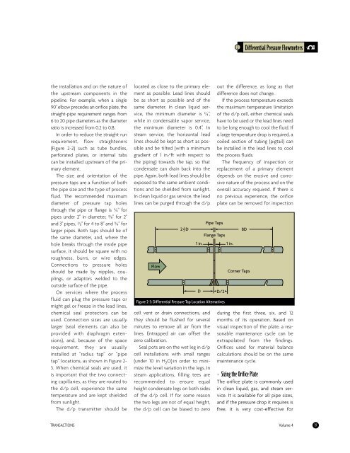
On services where the process<br />
fluid can plug the pressure taps or<br />
might gel or freeze in the lead lines,<br />
chemical seal protectors can be<br />
used. Connection sizes are usually<br />
larger (seal elements can also be<br />
provided with diaphragm extensions),<br />
<strong>and</strong>, because of the space<br />
requirement, they are usually<br />
installed at “radius tap” or “pipe<br />
tap” locations, as shown in Figure 2-<br />
3. When chemical seals are used, it<br />
is important that the two connecting<br />
capillaries, as they are routed to<br />
the d/p cell, experience the same<br />
temperature <strong>and</strong> are kept shielded<br />
from sunlight.<br />
The d/p transmitter should be<br />
located as close to the primary element<br />
as possible. Lead lines should<br />
be as short as possible <strong>and</strong> of the<br />
same diameter. In clean liquid service,<br />
the minimum diameter is G",<br />
while in condensable vapor service,<br />
the minimum diameter is 0.4". In<br />
steam service, the horizontal lead<br />
lines should be kept as short as possible<br />
<strong>and</strong> be tilted (with a minimum<br />
gradient of 1 in/ft with respect to<br />
the piping) towards the tap, so that<br />
condensate can drain back into the<br />
pipe. Again, both lead lines should be<br />
exposed to the same ambient conditions<br />
<strong>and</strong> be shielded from sunlight.<br />
In clean liquid or gas service, the lead<br />
lines can be purged through the d/p<br />
Flow<br />
2 1 D<br />
2<br />
cell vent or drain connections, <strong>and</strong><br />
they should be flushed for several<br />
minutes to remove all air from the<br />
lines. Entrapped air can offset the<br />
zero calibration.<br />
Seal pots are on the wet leg in d/p<br />
cell installations with small ranges<br />
(under 10 in H 2 O) in order to minimize<br />
the <strong>level</strong> variation in the legs. In<br />
steam applications, filling tees are<br />
recommended to ensure equal<br />
height condensate legs on both sides<br />
of the d/p cell. If for some reason<br />
the two legs are not of equal height,<br />
the d/p cell can be biased to zero<br />
Pipe Taps<br />
Flange Taps<br />
1 in. 1 in.<br />
D D/2<br />
Figure 2-3: Differential Pressure Tap Location Alternatives<br />
2 Differential Pressure Flowmeters<br />
out the difference, as long as that<br />
difference does not change.<br />
If the process temperature exceeds<br />
the maximum temperature limitation<br />
of the d/p cell, either chemical seals<br />
have to be used or the lead lines need<br />
to be long enough to cool the fluid. If<br />
a large temperature drop is required, a<br />
coiled section of tubing (pigtail) can<br />
be installed in the lead lines to cool<br />
the process fluids.<br />
The frequency of inspection or<br />
replacement of a primary element<br />
depends on the erosive <strong>and</strong> corrosive<br />
nature of the process <strong>and</strong> on the<br />
overall accuracy required. If there is<br />
no previous experience, the orifice<br />
plate can be removed for inspection<br />
Corner Taps<br />
during the first three, six, <strong>and</strong> 12<br />
months of its operation. Based on<br />
visual inspection of the plate, a reasonable<br />
maintenance cycle can be<br />
extrapolated from the findings.<br />
Orifices used for material balance<br />
calculations should be on the same<br />
maintenance cycle.<br />
• Sizing the Orifice Plate<br />
The orifice plate is commonly used<br />
in clean liquid, gas, <strong>and</strong> steam service.<br />
It is available for all pipe sizes,<br />
<strong>and</strong> if the pressure drop it requires is<br />
free, it is very cost-effective for<br />
TRANSACTIONS Volume 4 19<br />
8D


