

flow and level measurement - Omega Engineering
flow and level measurement - Omega Engineering
flow and level measurement - Omega Engineering

You also want an ePaper? Increase the reach of your titles
YUMPU automatically turns print PDFs into web optimized ePapers that Google loves.
lowers pumping costs <strong>and</strong> aids<br />
gravity feed systems.<br />
• Problem Applications<br />
The magmeter cannot distinguish<br />
entrained air from the process fluid;<br />
therefore, air bubbles will cause the<br />
magmeter to read high. If the<br />
trapped air is not homogeneously<br />
dispersed, but takes the form of air<br />
slugs or large air bubbles (the size of<br />
the electrode), this will make the<br />
output signal noisy or even disrupt it.<br />
Therefore, in applications where air<br />
entrainment is likely, the meter<br />
should be sized so that the <strong>flow</strong><br />
velocity under normal <strong>flow</strong> conditions<br />
is 6-12 ft/sec.<br />
Coating of the electrodes is another<br />
common magmeter problem.<br />
Material build-up on the inner surfaces<br />
of the meter can electrically isolate<br />
the electrodes from the process<br />
fluid. This can cause a loss of signal or<br />
a <strong>measurement</strong> error, either by changing<br />
the diameter of the <strong>flow</strong>tube or<br />
by causing span <strong>and</strong> zero shifts.<br />
Naturally, the best solution is prevention.<br />
One preventive step is to size the<br />
meter such that, under normal <strong>flow</strong><br />
conditions, the <strong>flow</strong>ing velocity will<br />
be relatively high: at least 6-12 ft/sec,<br />
or as high as practical considering the<br />
possibility of erosion <strong>and</strong> corrosion.<br />
Another method of prevention is<br />
to use electrodes that protrude into<br />
the <strong>flow</strong> stream to take advantage of<br />
the turbulence <strong>and</strong> washing effect. In<br />
more severe service, a mechanical<br />
cleaning system can be installed <strong>and</strong><br />
used intermittently or continuously<br />
to eliminate coating <strong>and</strong> build-ups.<br />
• Installation<br />
The magnetic <strong>flow</strong>meter must<br />
always be full of liquid. Therefore,<br />
the preferred location for magmeters<br />
is in vertical upward <strong>flow</strong> lines.<br />
Installation in horizontal lines is<br />
acceptable if the pipe section is at a<br />
low point <strong>and</strong> if the electrodes are<br />
not at the top of the pipe. This prevents<br />
air from coming into contact<br />
with the electrodes. When the<br />
process fluid is a slurry <strong>and</strong> the magmeter<br />
is installed at a low point, it<br />
should be removed during long periods<br />
of shutdown, so that solids will<br />
not settle <strong>and</strong> coat the internals.<br />
If it is essential to drain the magmeter<br />
periodically, it should be provided<br />
with an empty tube zero<br />
option. When this option is activated,<br />
the output of the transmitter will<br />
be clamped to zero. Detection of<br />
empty tube conditions is by circuitry<br />
connected to extra sets of electrodes<br />
in the <strong>flow</strong>tube. The empty<br />
tube zero feature can also be activated<br />
by an external contact, such as<br />
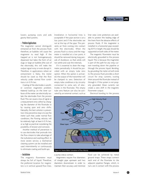
Flow<br />
Still Fluid<br />
Shear Layer<br />
1D V<br />
Figure 4-4: Vortex Meter Calculation of Flow Velocity<br />
a pump status contact.<br />
Magmeters require five diameters<br />
of straight pipe upstream <strong>and</strong> two<br />
diameters downstream in order to<br />
maintain their accuracy <strong>and</strong> minimize<br />
4 Electronic Flowmeters<br />
liner wear. Liner protectors are available<br />
to protect the leading edge of<br />
the liners from the abrasive effects of<br />
process fluids. If the magmeter is<br />
installed in a horizontal pipe exceeding<br />
30 ft in length, the pipe should be<br />
supported on both sides of the meter.<br />
The magnetic <strong>flow</strong>meter must be<br />
electrically grounded to the process<br />
liquid. This is because the magmeter<br />
is part of the path for any stray current<br />
traveling down the pipeline or<br />
through the process liquid. Bonding,<br />
by grounding the meter at both ends<br />
to the process fluid, provides a short<br />
circuit for stray currents, routing<br />
them around the <strong>flow</strong>tube instead of<br />
through it. If the system is not properly<br />
grounded, these currents can<br />
create a zero shift in the magnetic<br />
<strong>flow</strong>meter output.<br />
Electrical bonding to the process<br />
fluid can be achieved by metal<br />
ground straps. These straps connect<br />
each end of the <strong>flow</strong>tube to the<br />
adjacent pipeline flanges, which, in<br />
turn, are in contact with the process<br />
TRANSACTIONS Volume 4 49<br />
d<br />
High Velocity Fluid<br />
Alternative<br />
Vortices<br />
l


